| Journal of Renewable Materials |
DOI: 10.32604/jrm.2022.017275
ARTICLE
Mechanical Properties of Moso Bamboo Connections with External Clamp Steel Plates
1Key Laboratory of New Technology for Construction of Cities in Mountain Area (Chongqing University), Ministry of Education, Chongqing, 400045, China
2School of Civil Engineering, Chongqing University, Chongqing, 400045, China
3Suzhou Newcity Investment and Development Co., Ltd., Suzhou, China
4China Metallurgical Construction Engineering Group Co., Ltd., Chongqing, China
*Corresponding Author: Shidong Nie. Email: nieshidong@cqu.edu.cn
Received: 28 April 2021; Accepted: 23 June 2021
Abstract: The Moso bamboo, a renewable green building material used in various new green buildings, have received extensive attention with the promotion of the concept of green buildings. To explore the mechanical properties of Moso bamboo connections with external clamp steel plates, the 16 specimens were designed by changing the bolt diameters and the end distances of the bolt holes. Their static tension tests were conducted to investigate bearing capacities and failure modes of different connection configurations. Based on test results, three failure modes of these connections were obtained, including the shear failure of bolt shank, bearing failure of bolt hole and punching shear failure of the Moso bamboo. The influence of bolt diameters and end distances of bolt holes on bearing capacities of the connections was quantitatively analyzed. Based on a simplified mechanical model, the analytical models were deduced for the bolt shear failure and the bearing failure of bolt holes. The results showed that the predictive values are in substantial agreement with the experimental results. Finally, the design and manufacturing suggestions are recommended for this Moso bamboo connections.
Keywords: Moso bamboo connections; external clamp steel plates; load-carrying capacities; failure modes; the 5%d offset method; mechanical model
The green and environmentally friendly bamboo materials with excellent mechanical properties have been widely used in building structures with the introduction of the concept of sustainable development, such as the bamboo building as shown in Fig. 1. During the growth period of Moso bamboos, the amount of daily growth can reach 7.5~100 cm [1,2], therefore the Moso bamboos can be taken into use only after 3~6 years [3]. However, the growth period may be several decades [4] for conventional wood materials. Meanwhile, the cellulose content of the bamboos is higher than that of the wood. The cell arrangements of bamboos are axially strong, hence they have the higher ratio of strength-to-density compared with woods [5]. The advantages of bamboos, such as a short growth cycle, renewable use, the unique biological structure and high mechanical properties, make them popularly utilized with great engineering application potentials [6,7].
As a new building material, the potential mechanical properties of Moso bamboo materials have also attracted many attentions. Sonar et al. [8] proposed a connection configuration of a bamboo splint that was placed between two steel plates and was fixed with the steel plates with bolts. The influence factors of mechanical properties of the bamboo splint under axial tension were studied, based on which the test results showed that the end distance and diameter of the bolt can affect the ultimate bearing capacity of the connections, and the effective ranges of the bolt diameter were recommended. However, the bamboo pieces were used instead of complete bamboo components in Sonar et al.’s study, and were extracted from bamboos with a small diameter, which is limited in practical engineering applications. Lefevre et al. [9] proposed a bamboo connection with wood embedded and reinforced with steel hoops at the ends. The corresponding experiments showed that this connection could effectively improve the load-bearing capacity of connections, and their bearing capacities were related to the strength of the embedded wood. Fu et al. [10] put the steel sleeve into the bamboo tube, then injected the mortar between the sleeve and the bamboo inner wall, and finally used steel hoops to reinforce the end of the bamboo tube. Their tensile and compression tests showed that this connection had the good ductility and high load-carrying capacities, and could effectively transfer axial load. Awaludin et al. [11] used natural fibers and fiber-reinforced plastics to reinforce the connection of bamboos and investigated the effect of reinforcement methods on the mechanical properties of two connections. Ramful [12] designed several bamboo connections according to the strength and durability requirements of the connections under different loading conditions, and conducted the experimental investigation on their bearing capacities. The research showed that the connections connected with self-tapping bolts had the highest strength, followed by rivets connections. The connection bearing capacity was the smallest when the bamboo was only reinforced with steel hoops.
The bamboo connection configurations proposed by the above scholars are different. For these connections, the bolted connections are frequently used in bamboo buildings due to convenient installment as shown in Fig. 2 where there are steel-bamboo hybrid connections similar to steel-wood connections. However, the mechanical properties of bamboos and woods are quite different [13], and this connection as shown in Fig. 2 needs to be attentively scrutinized. In this paper, the mechanical tests for the Moso bamboo connection with external clamp steel plates and bolts were carried out. By changing the end distance of bolt hole and the bolt diameter in the connection, the failure modes and bearing capacities of the connection were studied based on experimental and theoretical investigations, and the theoretical formulae for the current connections were derived to provide references for the design and applications of Moso bamboo connections with external clamp steel plates or the U-shaped steel plates (hereinafter referred to as MBCECSP).

Figure 1: The bamboo building

Figure 2: Bamboo structure with bolted connections
2.1 Mechanical Properties of Moso Bamboos
The Moso bamboos used in the test were extracted from Moso bamboo in Anji Zhejiang. Their age is usually 5–6 years, and their moisture content is controlled at 12 ± 3%. There are unavoidable variabilities (or coefficients of variation as referred to as COVs) in the mechanical properties of biological materials. In this paper, a batch of test specimens against Moso bamboo materials were made in accordance with the Chinese industry standard JG/T 199-2007 [14] to investigate the relevant behavioural parameters of Moso bamboos, including the tensile, compressive and shear strengths in the longitudinal direction besides their moisture content, as shown in Figs. 3 and 4 for the typical material tests, respectively. To obtain the more accurate material parameters, the 40 standard specimens for each set of test to eliminate the variability of material properties. The different test results are shown in Tab. 1 where the COVs for three types of strengths are inferior to 0.2.


Figure 3: The size of test specimen (a) The size of tensile specimen, (b) The size of compressive specimen, (c) The size of shear specimen

Figure 4: Tests of mechanical properties of Moso bamboo (a) Tests of tensile strength, (b) Tests of compressive strength, (c) Tests of shear strength
The outer diameters of the Moso bamboos used for the tested specimens are about 90~110 mm, and the diameter-to-thickness ratio D/t (the ratio of the outer diameter D of the Moso bamboo to the wall thickness t) was controlled within about 9~12. In this paper, a total of 16 connection test pieces was designed by controlling the end distance of bolt hole and the bolt diameter. There were four types of bolt end distances: 50, 80, 110, and 140 mm. To facilitate installation of the bolts in Moso bamboo connections, the diameter of the bolt hole in the Moso bamboo had the 2 mm larger clearance than that of the bolt. The ordinary galvanized bolts Grade 4.8 were used in the test, and the bolts M8, M10, M12 and M14 were employed for these connection. The bolts were directly contacted with the bolt holes of Moso bamboos, and the steel plates were connected by two ordinary hexagon nuts with the same grade as the used bolts, as shown in Figs. 5 and 6. The specific parameters of each test specimen are shown in Tab. 2. The test specimen “OS-8-50” was taken as an example to illustrate the numbering rule: “OS” represents the name of the test specimen, “8” refers to the bolt type M8, and “50” means the bolt end distance of 50 mm.

The three sets of The U-shaped fixtures for loading were self-designed and customized. The bolt holes in each set of fixture were 10, 14, and 18 mm used to accommodate M8, M10 (M12) and M14 bolts, respectively. The six fixtures were made of Q235 steels with 40 mm width and 6 mm thickness, as shown in Fig. 5 where the fillet welds were used to connect different steel plates.
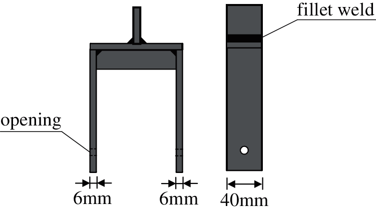
Figure 5: The U-shaped clamp fixtures

Figure 6: The bolt hole in direct contact with the bamboo
The connection tests were carried out by a universal testing machine with the maximum load 100 kN as shown in Fig. 7. The loading rate was 2 mm/min from the onset of loading to the failure of connection, and the axial static loading method was used to acquire the force-displacement curve of each connection. The tension test was stopped when the specimen was damaged. The chucks of the testing machine clamped the ends of the U-shaped fixtures, then the tensile force was transferred to the steel plates on both sides through the U-shaped connectors. Subsequently, the steel plates transmitted the tensile force to the bolt through the bolt hole. Finally, the bolt extruded the bolt hole wall of the Moso bamboo, then the Moso bamboo began to bear the force, thus the slippage stage between the various components ended, followed by the elastic stage in the force-displacement curve.
3 Test Results and Discussions
3.1 Bearing Capacities and Failure Modes of Connections
Typical load-displacement curves obtained from the uniaxial tension tests are shown in Fig. 8. According to ASTM D5764-97a [15], the 5%d offset method was used in the load-displacement curves to obtain the yield load Fy and yield displacement Δy. The ultimate load Fu and ultimate displacement Δu were acquired from the highest point in a load-displacement curve. Taking Fig. 8 as an example, the elastic stage (AB) in the load-displacement curve was linearly fitted to obtain the initial stiffness Kini; then the yield load Fy of the connection was obtained from the intersection point (Point C) between the load-displacement curve and the fitted stiffness line offset by a distance of 5%d, and then the yield displacement Δy corresponding to the intersection point was obtained. The peak load (Point D) in the load-displacement curve is the ultimate load, and the ultimate displacement Δu corresponding to Fu was also obtained. The crucial mechanical properties and failure modes of each type of connection were summarized in Tab. 3.
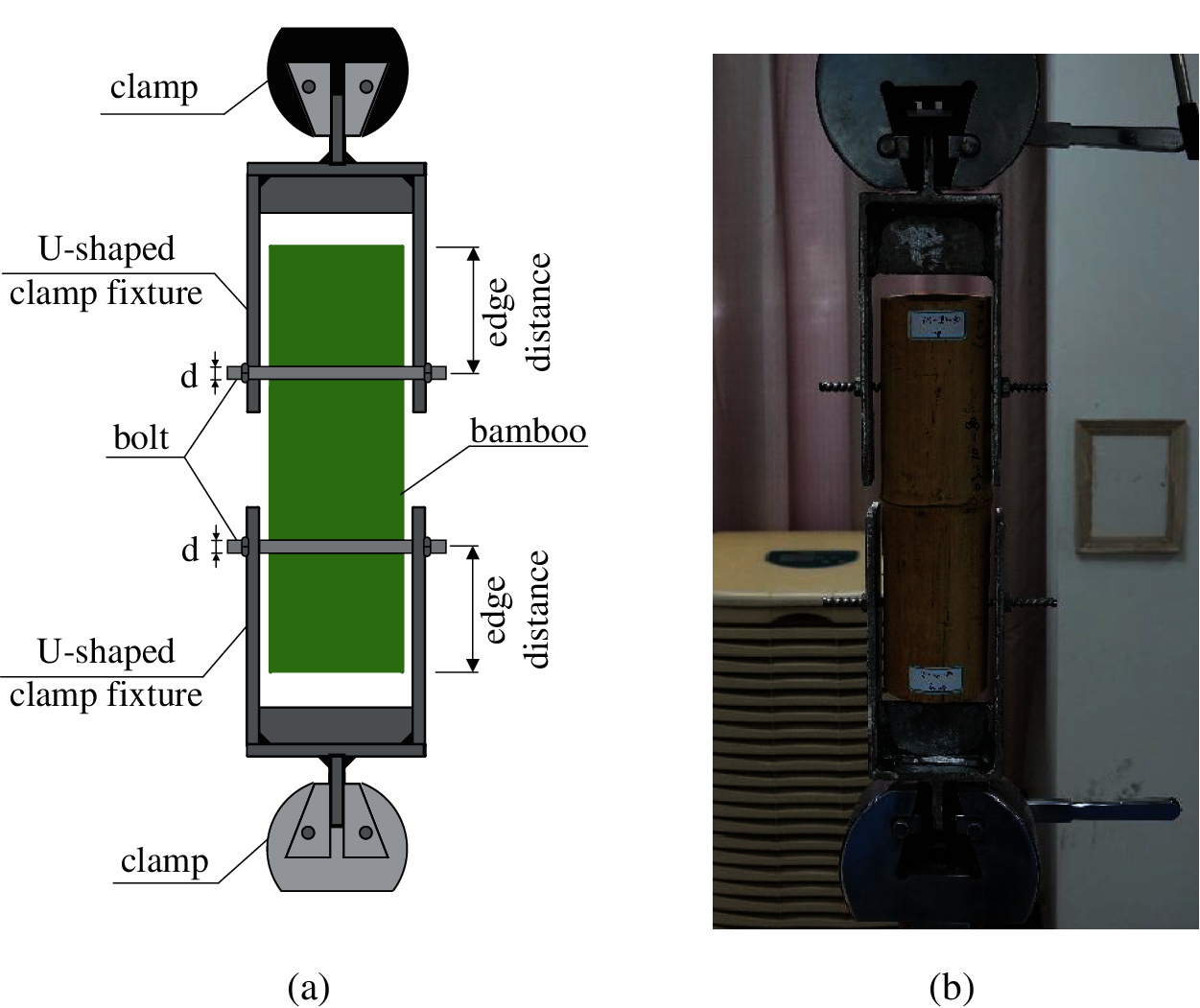
Figure 7: Test setup of Moso bamboo connections (a) Test setup, (b) Loading protocol

Figure 8: The 5%d offset method [15]
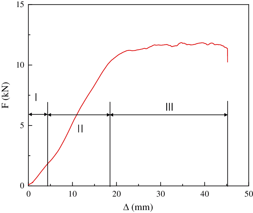
Figure 9: The deformation stages of specimens
The connection ductility can be characterized by the ratio of the ultimate-to-yield displacement, namely μ = Δu/Δy, where Δu and Δy are ultimate and yield displacements, respectively. This ratio value can feature the deformation capacity of the connection. From Tab. 3, it can be seen that the average ductility coefficient of the connection is 1.63, thus the connection has the good deformability.
From the load-displacement curves of the specimens, it can be found that they can be generally divided into three stages before failure, as shown in Fig. 9.
1) Initial slippage stage I: The initial displacement of the connection increased significantly while the specimen was subjected to a smaller tension, and the load-displacement curve showed a downward concave trend. This is because the clamped ends of the testing machine slipped at the beginning of being loaded. For example, the diameter of the bolt hole of the Moso bamboo was larger than that of the bolt. As the displacement increases, the components in the connection were in mutual contact, and the slipping transition stage ended.
2) Elastic deformation stage II: The connection displacement continued to increase after Stage I. After the connection experienced the initial stage, the components of the connection were tightly contacted in mutual interaction, the connection began to enter the stage of elastic deformation. The load-displacement curve became linear, and the bearing capacity and deformation gradually increased as the tension force continued to increase.
3) Plastic development stage III: The specimen entered the plastic development stage, and the connection displacement increased rapidly while the load increase was unobvious. The load-displacement curves were not smooth and had a serrated oscillation. This is because the fiber bundles adjacent to the bolt hole were constantly extruded and deformed by the bolt shanks until the connection failed.
For failure modes of the connections in all the tests, three typical failure modes can be noted, as shown in Fig. 10. These failure modes were mainly controlled by the bolt diameters and the end distances of bolt holes. The failure processes of the three failure modes were separately analyzed. The classifications for the different failure modes of the different connection specimens can be seen in Tab. 3.
1) Failure mode I (Fig. 10a): Bolt shear failure. Considering the fact that the outer diameters of the Moso bamboo are different from the identical specimen, there was a gap between the outer bamboo wall and the U-shaped fixture, as shown in Fig. 11. In engineering applications, the Moso bamboo has outwardly convex surfaces, which also created a gap between the bamboo wall and the steel plate. The gap led to the additional bending moment generated by the collinear shear force of the bolt, thus the bolt underwent the combined action of bending and shear. When the diameter of the bolt was small, the bending resistance was lower, followed by bending and deformation. Under the combined action of bending and shear, the bending plastic hinges emerged and shear failure eventually occurred. The constraint force of the steel plate on the bolt was stronger than that of the Moso bamboo, therefore the bending plastic hinges of the bolt produced at the opening of the steel plate. Meanwhile, the degree of compression on both sides of bolt hole was different. The yield-bearing degree close to the green side of the bamboo was significantly greater than that of the yellow side because the bolt had a larger degree of bending.

2) Failure mode II (Fig. 10b): Bearing failure of the bolt hole. The bolt holes yielded and then failed under continuous tension. When the bolt diameter was large and the gap between the Moso bamboo and the fixture was small, the bolt undertook the additional bending moment, and the bearing capacity was large enough. As the tension load increased, the slotted area of the Moso bamboo hole was continuously squeezed, and the fiber bundles became unstable and the bolt slipped, resulting in the slotted bolt hole under yield and damage conditions. Meanwhile, the slotted hole wall was flat, and the deformation of the bolt was small. When the sliding distance of the bolt was too large in some connections, the cracks close to the bolt hole of Moso bamboo eventually emerged at the bolt holes. This failure mode is considered a ductile failure mode.
3) Failure mode III (Fig. 10c): the punching shear failure of Moso bamboos. When the diameter of the bolt was large and the gap was small between the Moso bamboo and the fixture, the bolt did not bear additional bending moments. When the end distance of the bolt hole was also small, the yield-bearing capacity of the Moso bamboo holes was greater than the shear-bearing capacity of the Moso bamboo. As the tension load increased, the bearing resulting from yielding occurs, and the yielding degree was small. Then the punching shear failure eventually occurred. The punching shear surfaces generated on both sides of the bolt. The bolt pushed out the Moso bamboo directly from the punching shear surfaces, and even through-cracks might appear, as shown in Fig. 10, the hole wall is rough and the fiber bundles are distributed in disorder. The failure mode is considered as a brittle failure mode.

Figure 10: Three typical failure modes of MBCECSP. (a) Bolt shear failure, (b) Bearing failure in bolt holes, (c) The punching shear failure
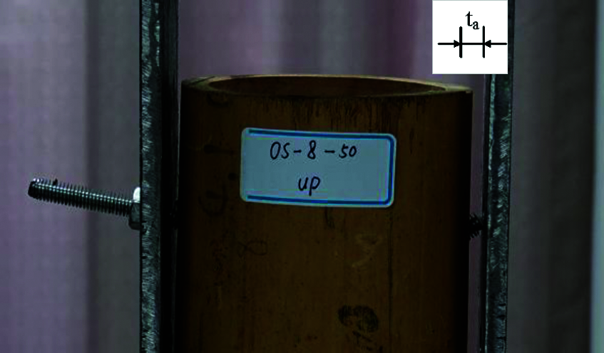
Figure 11: Gaps between the Moso bamboo and the steel plates
3.2 The Influence of Bolt Diameter
The load-displacement curves of the connections were classified according to the different bolt end distances, as shown in Fig. 12. As the diameter of the bolt increase, the variation of the yield capacity Fy and ultimate bearing capacity Fu of each connection is shown in Figs. 13 and 14 where the connection yield capacity Fy and ultimate bearing capacity Fu both increased with the increase of bolt diameter under the same bolt end distance, and the curve was linearly increased. But the increase amplitude of yield capacity Fy decreased when the bolt diameter was too large.

Figure 12: Load-displacement curves classified by the end distances (a) 50 mm, (b) 80 mm, (c) 110 mm, (d) 140 mm

Figure 13: The influence of bolt diameter on yield load capacity

Figure 14: The influence of bolt diameter on ultimate load capacity
As a biological material, the wall thicknesses of Moso bamboo are of slight differences for the identical Moso bamboo. Therefore, the average value tm of t1, t2, t3 and t4 was taken as the standard wall thickness, as shown in Fig. 15. The average wall thickness of each connection is shown in Tab. 2. The connection failure modes mainly resulted from the bearing bolt hole in the current study, and the bearing area is closely related to the wall thickness of the Moso bamboo. To eliminate the influence of the wall thickness on the bearing capacity of the connection, the connection bearing capacity Fy and Fu obtained in the test was respectively divided by the average wall thickness tm to obtain the bearing capacities Fy,m and Fu,m based on the unit wall thickness. The calculation method of connection bearing capacity is shown in Eq. (1), and the calculation results are shown in Tab. 3.

Figure 15: Wall thickness measurement method
The bearing capacities per unit wall thickness in the connections with different bolt diameters are shown in Figs. 16 and 17 under the same bolt end distance. As the bolt diameters increase, the bearing capacity related to the unit wall thickness under various bolt end distances increased. This is because the bolt diameter is too large and their performance is not fully utilized. The connection bearing capacity is controlled by the Moso bamboo which is the weakest member. However, there are also some exceptional connections, such as this connection by name of OS-14-110. The bearing capacity per unit wall thickness decreases slightly when the bolt diameter was increased. This is because the bolt hole position was not even with non-uniform bolt force on both sides, leading to the connection failure earlier.
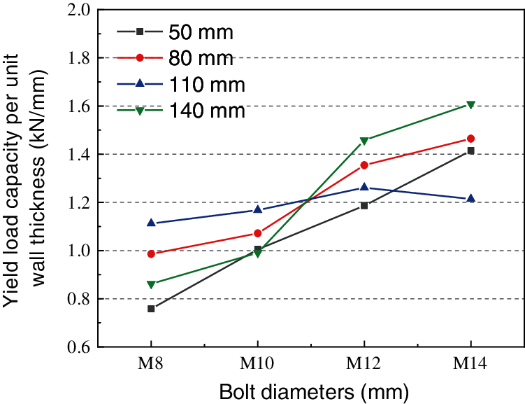
Figure 16: Yield load capacities per unit wall thickness

Figure 17: Ultimate load capacities per unit wall thickness
To analyze the increasing level of the connection bearing capacity when the bolt diameter increases, the curves of the increase of the yield-bearing capacity ΔFy and the ultimate bearing capacity ΔFu of each connection were drawn according to Eq. (2) where the bolt M12 was set as an example. The calculation method of the increasing level of the other connections is similar, as shown in Figs. 18 and 19.

Figure 18: Variation of yield load capacities

Figure 19: Variation of ultimate load capacities
When the bolt diameter was increased from M8 to M10 or M12, the effect of the bolt diameters on improving the yield bearing capacity and ultimate bearing capacity of the connection is particularly obvious. For example, when the bolt end distance is 50 mm, the yield-bearing capacity of the M10 bolt was increased by 34.29% and the ultimate bearing capacity was increased by 40.33% compared with the connection connected by M8 bolt. When the bolt end distance is 140 mm, the yield-bearing capacity of the connection using the M12 bolt was increased by 66.7% and the ultimate bearing capacity was increased by 37.18% compared with the connection connected by M8 bolt. But the increase in the bearing capacity of each connection was significantly reduced when the M14 bolt was used for the connection. Because the Moso bamboo is the weakest component, the increase in the bolt diameter cannot improve the bearing capacity of the connection, which indicates that the required bolt diameter in the connection is not large enough.
The failure modes of each connection were classified according to different bolt diameters, and their specific distribution is shown in Fig. 20. Failure mode I (bolt shear failure) appeared in the connection with M8 and M10 bolts due to the large gap between the steel plate and the Moso bamboo (Fig. 11) and the small bolt diameter. When ensuring that the gap between the steel plate and the Moso bamboo is small and avoiding the bending moment of the bolt, the connection using the M8 bolt could have good ductility failure (failure mode II). As shown in Fig. 21, this connection, OS-8-80, failed in the bearing conditions. Failure mode III (punching shear failure of Moso bamboos) occurred except the connections with M8 bolts, which is mainly controlled by the end distance.

Figure 20: Distributions of failure modes

Figure 21: The connection specimen OS-8-80
3.3 The Influence of Bolt End Distance
The load-displacement curves of the connections are classified according to the different bolt diameter, as shown in Fig. 22. As the end distance increases, the changing trends of the yield-bearing capacity and ultimate bearing capacity of each connection are shown in Figs. 23 and 24, respectively. The connection bearing capacities did not increase with the increase of the end distance under the same bolt diameter but different end distance. For example, the connection bearing capacities with different bolts decreased when the end distance was 110 mm.
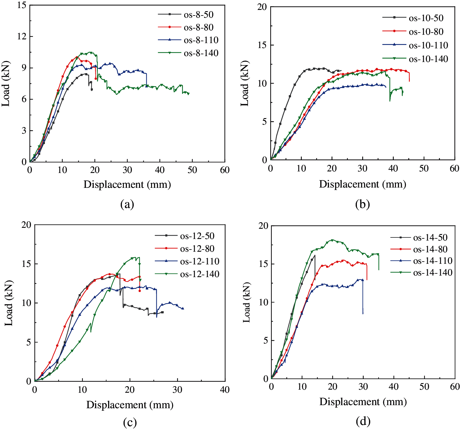
Figure 22: Load-displacement curves classified by bolt diameters (a) M8, (b) M10, (c) M12, (d) M14

Figure 23: The effect of end distances on yield load capacities

Figure 24: The effect of end distances on ultimate load capacities
The bearing capacity curves of connections per unit wall thickness can be seen in Figs. 25 and 26. When M8 or M10 diameter bolts were used for connection, the yield capacity per unit wall thickness of connections Fy,m first increases and then decreased with the increase of the end distance, but the increase or decrease of the connection bearing capacity is not obvious. The maximum yield-bearing capacity appears in the connection with an end distance of 110 mm; when the connection was connected by M12 or M14 diameter bolts, The yield-bearing capacity per unit wall thickness of the connection Fu,m also fluctuates with the increase of the end distance but the fluctuation range is small.

Figure 25: Yield load capacity per unit wall thickness

Figure 26: Ultimate load capacity per unit wall thickness
The variation amplitude of yield capacity ΔFy and ultimate capacity ΔFu in each connection is shown in Figs. 27 and 28 as the end distances of the bolt holes increase, and the calculation formulae as represented in Eq. (2). When the end distance was 110 mm in the connection with the M14 bolt, the yield-bearing capacity Fy and ultimate bearing capacity Fu of the connection were more significantly reduced compared with that with the end distance of 80 mm, and the yield-bearing capacity Fy was reduced by 20.08%. The ultimate bearing capacity Fu was reduced by 16.49%. When the end distance is changed to 140 mm, the yield capacity Fy of the connection was increased by 43.49% compared with the end distance of 110 mm.

Figure 27: The variation curves of yield load capacities

Figure 28: The variation curves of ultimate load capacities
The failure modes of each connection were classified according to different end distances to describe their specific distributions as shown in Fig. 29. Except the case where the end distance is 80 mm, the failure mode I (bolt shear failure) occurred at the other end distances. According to the previous analysis, the main influence factors of the failure mode I resulted from the gap between the steel plate and the Moso bamboo, which should be avoided during bamboo connection processing. The failure mode II (bearing failure), the main failure mode, is more evenly distributed. Failure mode III (punching and shear failure) only appeared when the end distance is 50 mm. All failure modes were classified according to the ratio value l/d in which l is the end distance and d is the bolt diameter as shown in Fig. 30. The values of l/d in failure mode III are concentrated in the range of 3.57~5.00. It can be seen that Moso bamboo is prone to punching shear failure when the end distance is insufficient. This case should be avoided by restricting the end distance. This paper recommends the value l/d ≥ 8.

Figure 29: Distribution of failure modes of different end distances
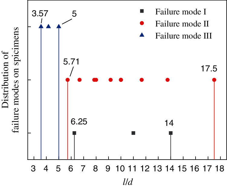
Figure 30: Distribution of l/d under different failure modes
Based on the above analysis, the force mechanism of the connections was simplified according to their failure characteristics. Then a simplified mechanical model of the Moso bamboo connection was established. Based on the mechanical equilibrium principle associated with the four basic assumptions as follows, the theoretical bearing capacity of the connections was predicted, which can provide a reference for the design of connection bearing capacity.
The basic assumptions:
(1) Ignore the tangential friction between the bolt and the Moso bamboo dowel groove;
(2) Ignore the friction between the U-shaped fixture and the outer wall of the Moso bamboo;
(3) The bolt holes on both sides of the Moso bamboo align with the uniform force;
(4) The wall thickness of the Moso bamboo is uniform, and there are no significant differences in the wall thicknesses.
According to the above analysis, two conditions must be met for bolt shear failure of the connection: (1) There is a gap ta between the outer wall of the Moso bamboo and the steel plate; (2) The bolt diameter is small and its bending resistance is weak. From the fracture situation of the bolt in Fig. 11, the plastic hinge occurred on the side of the steel plate hole. This is because the steel plate has a stronger binding force on the bolt than the bamboo walls, and the steel plate is equivalent to the fixed end of the bolt. Therefore, the force mechanism of the bolt shear failure is simplified, as shown in Fig. 31.
According to the force diagram of the bolt shear failure in Moso connections, the mechanical equilibrium equations were obtained, as represented by Eq. (3). Then Eq. (3) was rearranged to obtain Eq. (4).
where
F1 is the design value for the bearing capacity of the connection, kN;
fem is the compressive strength of Moso bamboo along the grain, which can be obtained according to material property test, N/mm2;
fs is the compressive stress of the bolt in the steel plate opening, N/mm2;
Mu is the plastic bending moment of the bolt, N/mm2;
d is the bolt diameter, mm;
ta is the distance between the outer wall of the Moso bamboo and the steel plate, mm;
tb is the wall thickness of the Moso bamboo in the specimen, mm;
ts is the thickness of the clamped steel plate in the specimen, mm, ts = 6 mm;
t1, t2 are the length of the squeezed areas within the wall thickness of the Moso bamboo, mm;
According to NDS-2005 [16], Considering that the plasticity of the bolt is fully developed, the plastic bending moment Mu of the bolt is denoted in Eq. (5).
where fub is the bolt tensile strength; the galvanized bolt Grade 4.8 is used in the test; fub = 400 Mpa [17]; kw is the bolt plastic development coefficient, kw = 1.7.
Combining Eq. (4) with Eqs. (5), (6) can be acquired according to the root-finding formula neglecting the negative solution.

Figure 31: The bolt shear failure
According to Eq. (6), the load-bearing capacities of connections were respectively calculated when ta = 0, ta = 0.5tb and ta = tb to study the influence of the gap ta between the outer wall of the Moso bamboo and the steel plate on the bearing capacity in the connection, as shown in Tab. 4. The average distance ta = 0.5tb was adopted in this test. The average ratio of the test-to-prediction results is 1.05 when ta = 0.5tb, which indicates that this formula can predict the load-bearing capacity of the connection well. When the gap ta increased from 0 to tb, the calculated bearing capacity of the connection was reduced by about half. The gap has a great influence on the bearing capacity of the connection and should be minimized during processing.

As a main failure mode in bamboo connections, the bearing failure is an ideal ductile failure. The force mechanism is shown in Fig. 32 where the mechanical equilibrium equation can be obtained, as seen in Eq. (7).
where
F2 is the design value for the bearing capacity of the connections, kN;
fem is the compression strength of Moso bamboo, which can be obtained according to material property test, N/mm2;
d is the bolt diameter, mm;
tb is the wall thickness of the Moso bamboo, mm;
The test and prediction results of load-bearing capacities in each connection are compared and analyzed, as shown in Tab. 5. Based upon the devived formula for the load-bearing capacity of the bolt hole, the test values are close to the prediction results, and their ratio range of test-to-prediction results is 0.74~1.15. The average ratio between the test and prediction results is 0.96, indicating that the proposed formulas can effectively predict the ultimate load of bamboo connection with bearing failure modes. To ensure safety in the connections, referring to the GB 50005-2017 [18], the safety factor is recommended to be 3.0, thus ensuring a certain degree of bearing capacity in the bamboo connections.


Figure 32: Bearing failure of the bolt hole
Based on the static tension tests of bolt the Moso bamboo connections with external clamp steel plates, the influence of the bolt diameters and the end distances were considered, and the failure modes and bearing capacities of the connection were studied. Based on the mechanical equilibrium equations, the calculation formulas for the bolt shear failure and bearing failure were derived. This study can reveal the following conclusions:
1) The connection mechanism of MBCECSP can be divided into three development stages: initial slipping stage I, elastic deformation stage II and plastic development stage III. There are three failure modes of the connection: bolt shear failure, bearing failure of bolt hole and punching shear failure of Moso bamboo.
2) The main failure modes of MBCECSP are controlled by the bearing. The calculated values base a simplified model are close to the experimental results, and the average experimental values are 0.96 times the calculated value. This formula can be used for connection design calculation. It is recommended to take the safety factor as 3.0 to ensure a safety store of bearing capacity.
3) The bearing capacities of bamboo connections increase with the increase of the bolt diameter, but the increasing effect is not obvious after the bolt diameter is too large; there is no obvious linear relationship between the end distance and the bearing capacity in the bamboo connections.
4) The shear failure of the bolt is affected by the gap. The ductile bearing failure occurs when the gap is small. It is when the gap between the outer clamp steel plate and the outer wall of the Moso bamboo is large and the bolt diameter is small that the bolt shear failure may occur under the combined action of bending and shear. Therefore, the excessive gaps should be avoided.
5) The punching shear damage of the Moso bamboos is likely to occur when the end distance of the bolt hole is small. This failure method can be avoided by limiting the relationship between bolt end distance and the bolt diameter to l/d ≥ 8.
Funding Statement: The authors would like to appreciate the support from the Graduate Research and Innovation Foundation of Chongqing in China (Grant No. CYS20026) and the National Key Research and Development Program of China (Grant No. 2017YFC0703504).
Conflicts of Interest: The authors declare that they have no conflicts of interest to report regarding the present study.
1. Cao, L., Coops, N. C., Sun, Y., Ruan, H. H., Wang, G. B. et al. (2019). Estimating canopy structure and biomass in bamboo forests using airborne lidar data. ISPRS Journal of Photogrammetry and Remote Sensing, 148, 114–129. DOI 10.1016/j.isprsjprs.2018.12.006. [Google Scholar] [CrossRef]
2. Shangguan, W. W., Zhong, Y., Xing, X. T., Zhao, R. J., Ren, H. Q. (2015). Strength models of bamboo scrimber for compressive properties. Journal of Wood Science, 61(2), 120–127. DOI 10.1007/s10086-014-1444-9. [Google Scholar] [CrossRef]
3. Chung, K. F., Yu, W. K. (2002). Mechanical properties of structural bamboo for bamboo scaffoldings. Engineering Structures, 24(4), 429–442. DOI 10.1016/S0141-0296(01)00110-9. [Google Scholar] [CrossRef]
4. Archila-Santos, H. F., Ansell, M. P., Walker, P. (2012). Low carbon construction using Guadua bamboo in Colombia. Key Engineering Materials, 517, 127–134. DOI 10.4028/www.scientific.net/KEM.517.127. [Google Scholar] [CrossRef]
5. Xiao, Y., Li, J. (2015). The state of the art of modern bamboo structures. Industrial Construction, 45(4), 1–6. DOI 10.13204/j.gyjz201504001. [Google Scholar] [CrossRef]
6. Xie, J. L., Qi, J. Q., Hu, T. X., De-Hoop, C. F., Hse, C. Y. et al. (2016). Effect of fabricated density and bamboo species on physical-mechanical properties of bamboo fiber bundle reinforced composites. Journal of Materials Science, 51(16), 7480–7490. DOI 10.1007/s10853-016-0024-3. [Google Scholar] [CrossRef]
7. Zhang, X. C., Zhou, Z. Z., Zhu, Y. D., Dai, J. F., Yu, Y. M. et al. (2019). High-pressure steam: A facile strategy for the scalable fabrication of flattened bamboo biomass. Industrial Crops and Products, 129, 97–104. DOI 10.1016/j.indcrop.2018.11.061. [Google Scholar] [CrossRef]
8. Sonar, I. P., Siddhaye, V. R. (2009). Theoretical and experimental investigation on single and double bolted bamboo joint under axial tension. Journal of Structural Engineering, 36(3), 164–171. [Google Scholar]
9. Lefevre, B., West, R., O’Reilly, P., Taylor, D. (2019). A new method for joining bamboo culms. Engineering Structures, 190(3), 1–8. DOI 10.1016/j.engstruct.2019.04.003. [Google Scholar] [CrossRef]
10. Fu, Y. G., Wang, M. Y., Ge, H. B., Li, L. (2012). Experimental study of mechanical properties of bamboo’s joints under tension and compression load. Advanced Materials Research, 450--451, 749–755. DOI 10.4028/www.scientific.net/AMR.450-451.749. [Google Scholar] [CrossRef]
11. Awaludin, A., Andriani, V. (2014). Bolted bamboo joints reinforced with fibers. Procedia Engineering, 95(1), 15–21. DOI 10.1016/j.proeng.2014.12.160. [Google Scholar] [CrossRef]
12. Ramful, R. (2018). Evaluation of the mechanical properties of bambusa bamboo culms with metallic joints through destructive testing. Journal of Green Building, 13(2), 1–19. DOI 10.3992/1943-4618.13.4.1. [Google Scholar] [CrossRef]
13. Fei, B. H., Zhang, D. S., Ren, H. Q., Wang, Z. (2008). The bearing capacity of the joint composed by laminated bamboo lumber. Journal of Nanjing Forestry University (Natural Sciences Edition), 32(3), 67–70. [Google Scholar]
14. JG/T 199-2007 (2007). Testing methods for physical and mechanical properties of bamboo used in building. Beijing, China: Architecture & Building Press. [Google Scholar]
15. ASTM D-5652 (1995). Standard test methods for bolted connections in wood and wood-based products. West Conshohocken, PA: American Society for Testing and Materials. [Google Scholar]
16. ANSI (2005). National design specification for wood construction. Washington DC: American Forest & Paper Association, Inc. [Google Scholar]
17. SAC (2010). Mechanical properties of fasteners Bolts, screws and studs GB/T 3098.1-2010. Beijing, China: Architecture & Building Press. [Google Scholar]
18. SAC (2017). Code for design of timber structures GB 50005-2017. Beijing, China: Architecture & Building Press. [Google Scholar]
 | This work is licensed under a Creative Commons Attribution 4.0 International License, which permits unrestricted use, distribution, and reproduction in any medium, provided the original work is properly cited. |