| Journal of Renewable Materials |
DOI: 10.32604/jrm.2022.018515
ARTICLE
Analysis of Crack Expansion and Morphology of Cross-Laminated Timber Planar Shear Test
1College of Materials Science and Engineering, Nanjing Forestry University, Nanjing, 210037, China
2College of Civil Engineering, Nanjing Forestry University, Nanjing, 210037, China
*Corresponding Author: Zheng Wang. Email: wangzheng63258@163.com
Received: 30 July 2021; Accepted: 02 September 2021
Abstract: To describe the dynamic cracking process of the CLT vertical layer, the correlation between a load-displacement curve, specimen cracking, and planar shear failure mechanism of the CLT were explored. A three-point bending test and an improved planar shear test are used to evaluate the shear performance of the CLT. In this study, the load-displacement curve is recorded, the experimental part is synchronized with the video, the dynamic process of cracking of the vertical layer is observed and analyzed throughout the test. From the load-displacement curve, the image characteristics of the initial cracking and the sudden increase of the cracking of the specimen are summarized. The description results of the whole dynamic process of the CLT vertical layer cracking are analyzed by planar shear strength value, cracking phenomenon, and azimuth angle of cracking surface. The main conclusions show that the three-point bending test and the improved plain shear test can be used to test the plain shear strength of the CLT, with a difference of only 5.7%. The original crack and the new crack expansion account for 18.9% and 81.1% of the main cracking surface, respectively. And the vertical layer of the CLT specimen under three-point bending has three cracking morphologies, such as radial shake, ring shake, neither along with the radial shake nor along with the ring shake. The azimuth angle of the cracking surface of the CLT vertical layer under planar shear is quite consistent with the first main plane azimuth of the vertical layer of the CLT specimens under the three-point bending test and the shearing test. The shape in the cracking direction of the left half-span or the right half-span of the vertical layer of the specimen is similar to the Chinese character eight.
Keywords: Cross-laminated timber; planar shearing performance; three-point bending test; improved planar shear test; crack expansion; dynamic process
Nomenclature
| ρ | Density |
| α | Tilt angle of the specimen |
| τ | Planar shear strength |
| Pmax | Maximum peak load |
| b | Width of the specimen |
| h | Thickness of the specimen |
| l | Length of the sample |
Timber structure buildings have a long history in construction and occupy a very important position in the history of world architecture. In recent years, a new generation of heavy timber structures, represented by Cross Laminated Timber (CLT), is partially replacing reinforced concrete and brick-mixed structures and being widely used in the construction of low, middle, and even high-rise civil housing and public buildings and other non-civilian buildings. Therefore, the CLT planar shear (rolling shear) strength is an indicator used to evaluate the mechanical properties of the CLT layers. The CLT is subjected to vertical loads when used as a floor and wind load when used as a wall panel [1–2], and shear deformation occurs under the influence of these forces [3–5], affecting the performance of the CLT board [6–8]. The gluing method and the grinding conditions of the glued surface also have an important influence on its mechanical strength [9,10]. Scholars all over the world are using different methods to study the mechanical properties of the CLT made from different origins and different materials [11–15]. Therefore, it is very important to study the shear strength of the CLT plane for structural applications and design optimization.
Based on the definition of planar shear in the standard ASTM D2718 [16], this study puts forward two methods for testing the strength of the CLT planar shearing (rolling shear), namely, the three-point bending test method [8] and the improved planar shear test [17], based on the fact that both methods can achieve the planar shearing of the CLT vertical layer at loading time. The three-point bending test method refers to the planar shearing of the CLT vertical layer, which length of the laminate is perpendicular to the grain direction of the surface wood, through the three-point bending load to test the planar shear strength (in-plane shear strength) of the CLT. The improved planar shear test method refers to the planar shearing of the CLT vertical layer through the tilted CLT shearing under the partial shaft compression load to test the planar shear strength of the CLT. To this end, on the one hand, the design and production of the CLT unit structure have been carried out. Since the CLT is a new type of wood composite building material, quality control of its processing and parameters is very important.
This study considers not only obtaining accurate strength values but also, exploring the correlation between the load-displacement curve and specimen cracking, and the new planar shear failure phenomenon of the CLT, through the description of the dynamic process of the CLT vertical layer cracking and analyzing and summaring the failure mode of the specimen during the whole experiment. Since the sawn timber used in this experiment is processed and manufactured in a conventional manner and has the same specifications, the influence of the position of the pith, the size of the annual ring, and the width of the annual ring will not be discussed further [18,19].
2.1 CLT Board Structure and Production
In this study, a Canadian hemlock (T. heterophylla) CLT plate structure with an equal thickness of 3 layers was designed. Following ANSI/APA PRG 320-2012 [20], CLT Manual Chapter II, medium relevant provisions [21], the production line completed the CLT board of 5500 mm × 1200 mm × 105 mm. Its entire processing includes sawn timber processing, mositure content control, appearance grading, stress grading, CLT substrate selection, truncation, cutting, gluing, assembly, cold pressure, and other processes. The thickness of the CLT unit is controlled to 35 mm at the time of manufacture, and the amount of glue is 180 g/m2 with a single-pack polyurethane (PUR) as an adhesive. The opening time from the beginning of the gluing to the beginning of cold pressure is controlled within 30 min, while the surface and side cold pressure are 1.2 and 0.3 MPa within 90 min, respectively.
2.2 The CLT Specimens and Test Equipment
2.2.1 The CLT Test Preparation
In this study, according to ANSI APA PRG320-2012 [19], a 3-layer hemlock CLT board with a size of 5500 mm × 1200 mm × 105 mm was sawn into shear specimens A and B for three-point bending test and shear specimen C for the improved planar shear test. The average moisture content of specimens is 9.5% and the average density ρ is 473 kg/m3, as shown in Fig. 1 and Tab. 1, respectively.
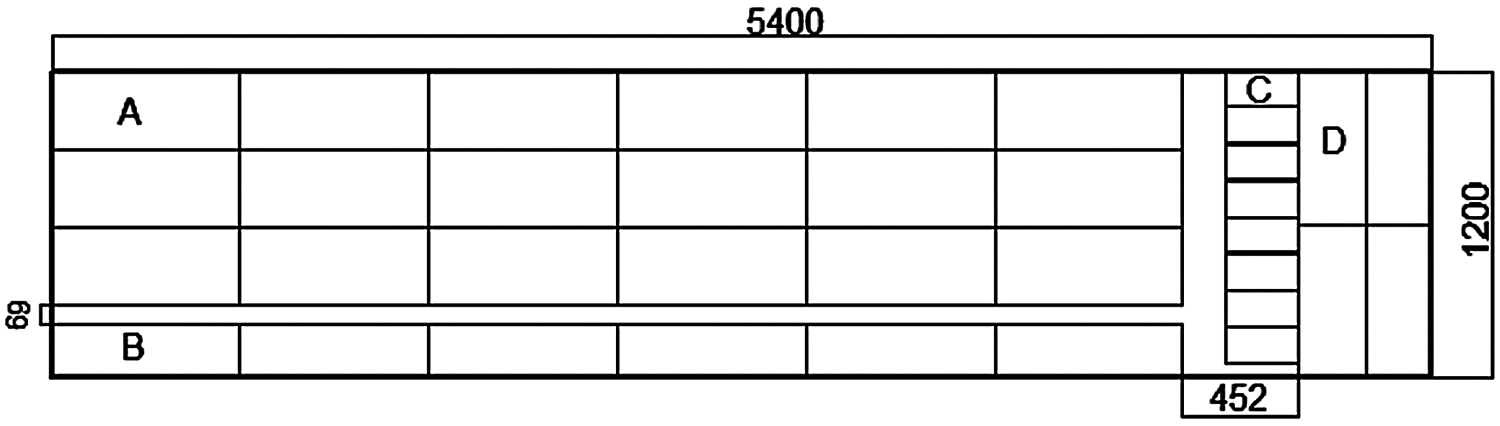
Figure 1: Schematic diagram of the sample sawing
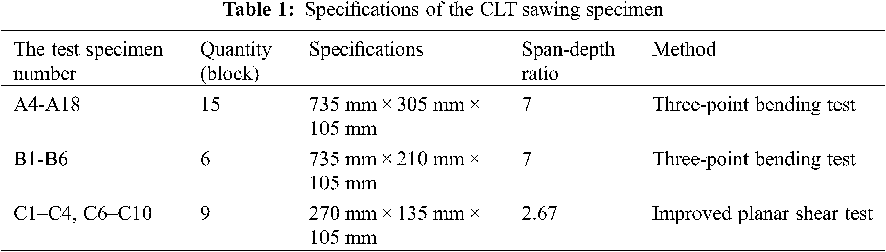
Fig. 1 is the schematic diagram of a single CLT whole board sawing. A1–A3 were rejected because of obvious defects after sawing. Therefore, in this experiment, the C specimen was derived from two CLT whole plates. The D specimens in this study were three-point bending specimens obtained by cutting along the minor strength direction of the CLT. In the test, it was found that when the D specimen was loaded, the adhesive layer cracked in its outermost layer. This was due to the large normal stress that the D specimen born and there was no bearing capacity on the vertical layer. Therefore, the test of D specimen was cancelled.
According to ANSI APA PRG320-2012 [20], the span-depth ratio of the three-point bending test is 5-6. The dimensions of the samples for the three-point bending are set as 735 mm × 305 mm × 105 mm and 735 mm × 210 mm × 105 mm, respectively to achieve the span-depth ratio of 6.
The advantage of the CLT’s improved planar shear test compared to the conventional planar shear tests specified in the ASTM D2718 [16] and EN 408 [22] standards is that there is no need to achieve planar shearing of the CLT vertical layer by loading the two steel plates fixed to the specimen. Fig. 2 shows the CLT’s improved planar shear specimen [23], starting with cutting the upper end face of the left parallel layer of the CLT block and the lower end face of the right parallel layer at a certain inclination angle α to a horizontal surface so that when the test specimen is placed, the centerline of the test specimen is tilted by a fixed angle α relative to the lead vertical line. Then, a pair of vertical pressure P passing through the center point O of the test specimen is added on the two cutting planes to realize the planar shearing of the CLT vertical layer.
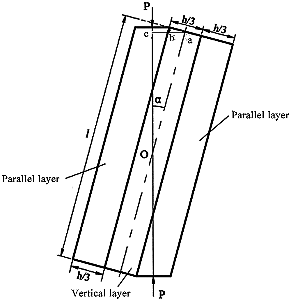
Figure 2: Schematic diagram of the CLT’s improved planar shear loading
The formula for determining the tilt angle α of the cutting parallel layer is derived as follows:
In Fig. 2, h is the height of the CLT specimen for the improved planar shear test, b is the width, l is the length, and the thickness of parallel layer-vertical layer-parallel layer is h/3 each. The CLT specimen is coupled with a pair of lead straight forces of equal size and opposite directions, the action line passes through the center of the test specimen, and the action points of the force are the center of the slope cut into the upper end of the left parallel layer, and the center of the bevel cut by the lower end face of the right parallel layer.
It is supposed that the inclination angle of the lead line at the center of the CLT specimen for the improved planar shearing and its centerline is α, in RtΔoca, therefore:
That is, the following triangular equations are satisfied:
When calculating the angle α, take the negative sign before the root number of the formula (1).
In this article, the size of C specimen is 270 mm × 135 mm × 105 mm, the calculated inclination angle α is 15.04°.
(1) JAW-2000 multi-channel structure test loading system 1 set, including load-displacement analysis software, the maximum test force of 300 kN, manufactured by Hangzhou Bonway Electrical and Mechanical Control Engineering Co., Ltd., China. This device is used for the three-point bending test.
(2) AG-IC-type electronic universal test machine 1 set, the maximum test force of 100 KN, manufactured by Shimadzu International Trade (Shanghai) Co., Ltd., China; This device is used for improved planar shear tests.
3 Description of the Full Dynamic Process of the CLT Planar Shear Test
3.1 The CLT Planar Shear Strength Calculation
A formula for calculating the shear strength of the CLT plane from the maximum load value obtained from the load-displacement curve.
A planar shear strength formula of the CLT three-point bending test [24] is as follows:
In formula (2): τ–the CLT planar shear strength, MPa; Pmax–the maximum peak load, N; b–the width of the specimen, mm; h–the thickness of the specimen, mm.
A planar shear strength formula of CLT improved planar shear testis as follows:
In formula (3): τ–the CLT planar shear strength, MPa; Pmax–the maximum peak load, N; l–the length of the sample, mm; b–the width of the width, mm; α–the tilt angle of the specimen.
3.2 A Description of the Test Dynamics of the Three-Point Bending Method
To explore the cracking behavior before the failure of the CLT under the three-point bending test, the load-displacement curve of specimens A and B, the test part, as well as the whole process of vertical cracking, crack expansion, and failure of the specimens are recorded in real time. The video and loading process of the specimen are synchronized until the end of the experiment.
In the Excel file of the load-displacement curve formed in this experiment, the load and load point displacement applied to the specimen corresponding to the loading moment are provided; in this study, the description of the whole dynamic process of the test will be carried out with the A9 specimen with a load speed of 0.5 mm/min as an example.
In this paper, the relationship between the load-displacement curve of the A9 specimen and the vertical layer cracking, crack expansion, and destruction is described by the time node as the contact point.
The load-displacement diagram of the A9 specimen and its key node results are shown in Fig. 3 and Tab. 2, respectively.
Figure 3: A load-displacement diagram of A9 specimen
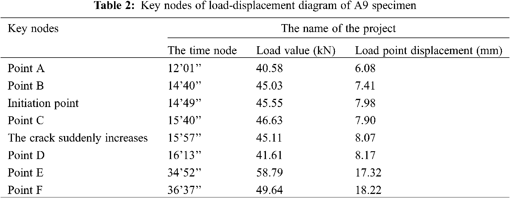
In Tab. 2, the peak load of the E-point is 58.79 kN, the specimen width b is 305 mm and the height h is 105 mm, and these values are substituted in formula (2). That is, the shear strength τ of the A9 specimen is 1.269 N/mm2, which is 1.269 MPa.
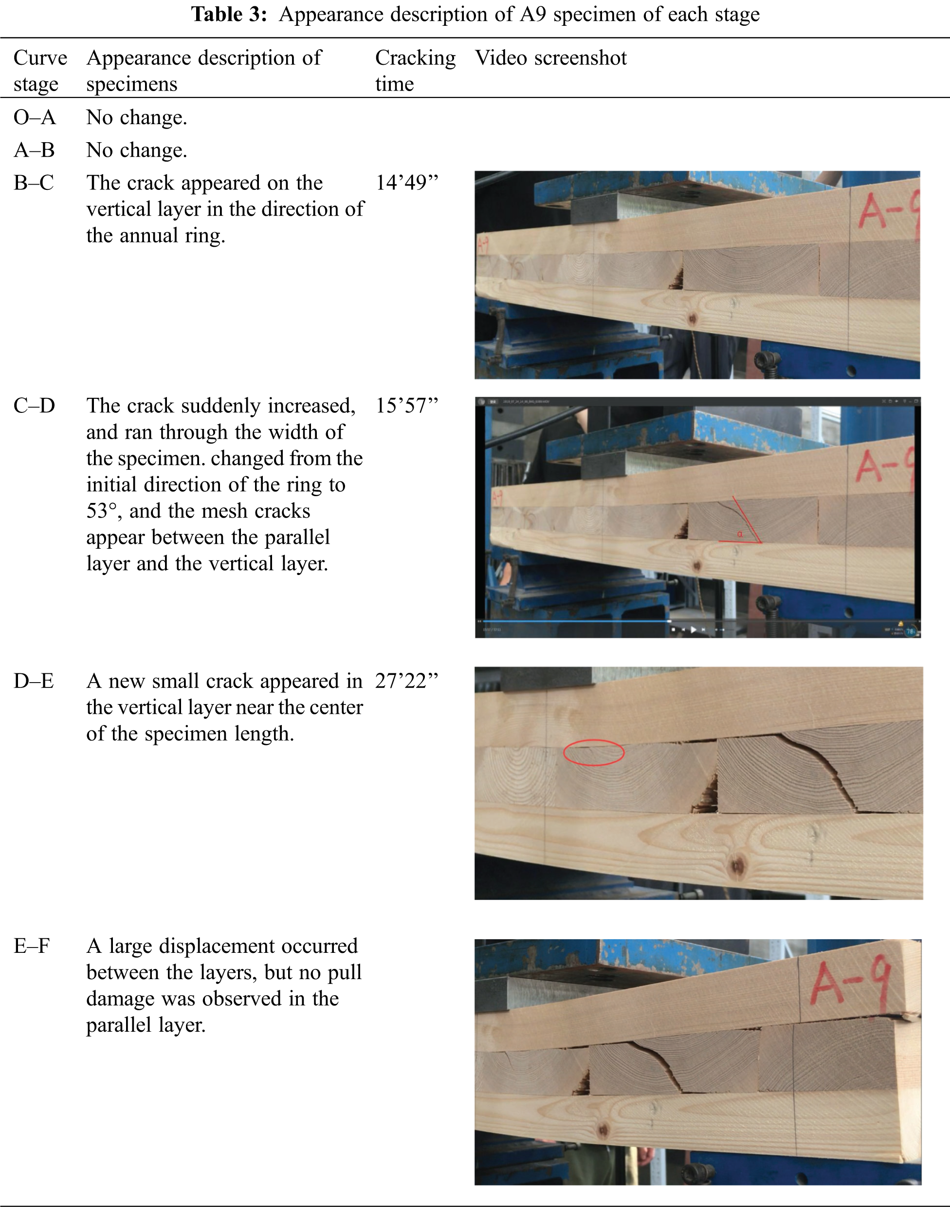
In Tab. 3, there are appearance description in the whole loading status of A9, and the video screenshots are also listed in the table.
3.3 Dynamic Full-Process Test of the Improved Planar Shear Test
To explore the difference between the results of test methods, and to obtain a more suitable test method combined with theoretical analysis, the planar shear strength of the CLT specimen is tested by the improved planar shearing. A comprehensive analysis is conducted by test values, the crack expansion in the dynamic process of shear failure in the load-displacement curve, the plane stress calculation, as well as the crack and its morphology, and its shear failure mechanism.
The shear specimen is placed up and down on the positioning aluminum block, the position is adjusted to ensure that the loading direction passes through the center of the specimen, the loading speed of the plane cut is 0.5 mm/min, using displacement control loading and recording its load-displacement curve. The specimen loading and load-displacement curve will be synchronized by video recording. Fig. 4 shows the two installation types of the C specimen before the test.
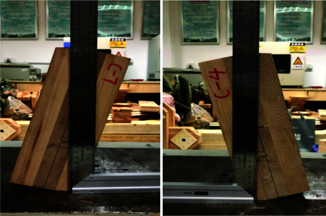
Figure 4: Installation types of C specimen before the test
In the Excel file of the load-displacement curve formed in this experiment, the load and load point displacement applied to the specimen corresponding to the loading moment are provided. Using the specimen video synchronized with the loading of the testing machine, and taking each time node on the load-displacement curve as the contact point, it is possible to describe the cracking, crack expansion, and the final failure form of the vertical layer at each stage of the load-displacement curve. Taking the C3 specimen as an example, the results and analysis of its shear performance are carried out using an improved planar shear test method.
In this paper, with its video observation, the relationship between the load-displacement curve of the C3 specimen and the vertical layer cracking, crack expansion, and failure is described by the time node as the contact point. The load-displacement diagram of the C3 specimen and its key node results are shown in Fig. 5 and Tab. 4, respectively.
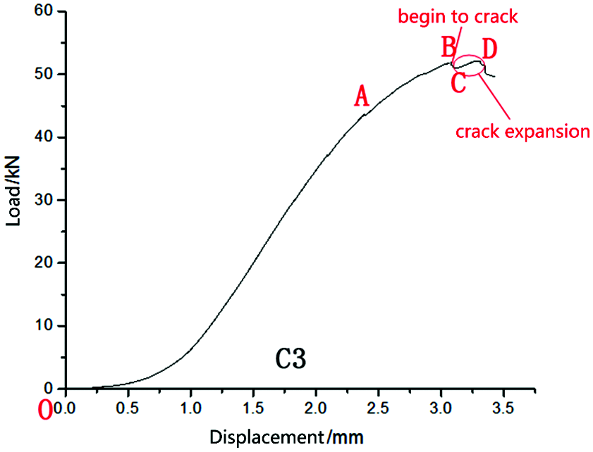
Figure 5: Load-displacement curve of the C3 specimen
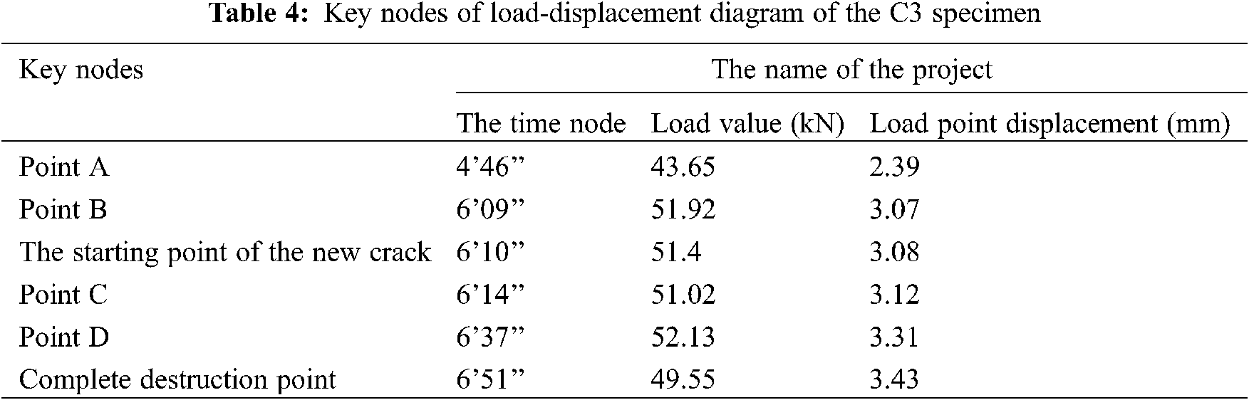
By the maximum peak load of 52.13 kN substituted into formula (3), the shear strength τ of the test specimen C3 is calculated as 1.38 MPa.
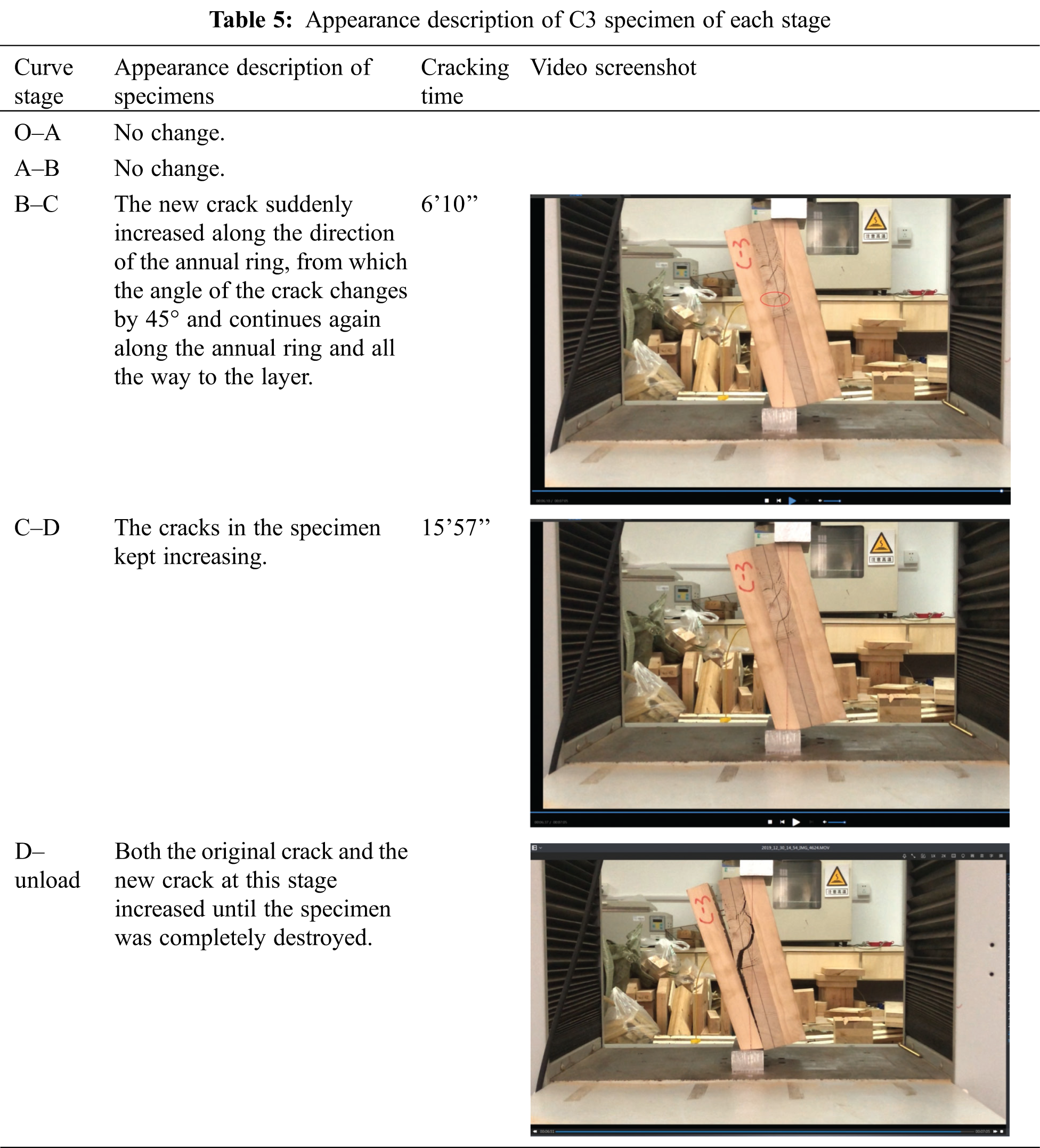
In Tab. 5, there are appearance description in the whole loading status of C3, and the video screenshots are also listed in the table.
4.1 Hemlock CLT Planar Shear Strength Test Value
Hemlock CLT specimens A and B were subjected to the three-point bending test, the maximum load value of the load-displacement curve can be obtained by the destruction test and then based on the formula (2) the test value of the planar shear strength of each hemlock CLT specimen can be to calculated. The average shear strength value of the A specimen with a total amount of 15 pieces and size of 735 mm × 305 mm × 105 mm is 1.32 MPa, the coefficient of variation (COV) is 10.3%, while the average shear strength value of the B specimen with dimensions of 735 mm × 210 mm × 105 mm is 1.33 MPa, and the corresponding COV is 10.5%. The average shear strength values of hemlock specimens A and B are basically equal, and its relative error is 0.8%, indicating that the shear strength value of hemlock CLT under the three-point bending test is not affected by the width of the specimen.
Hemlock CLT specimen C was subjected to the shear test, the maximum load value of the load-displacement curve can be obtained by the destruction test, and then according to the formula (3) the test value of the planar shear strength of each hemlock CLT specimen can be calculated; with a total amount of 9 specimens and size of 270 mm × 135 mm × 105 mm, the average shear strength value of specimens C is 1.25 MPa, and the corresponding COV is 24.7%.
Thus, the planar shear strength of hemlock CLT under the three-point bending test is quite consistent with the planar shear strength of hemlock CLT under the improved planar shear test, with a relative error of only 5.7%.
4.2 CLT Cracking Morphology and Azimuth Angle of Cracking Surface
The crack morphology and the azimuth angle of the cracking surface of the CLT three-point bending specimens and the plane shear specimens are shown in Tabs. 6 and 7, respectively. Interlayer cracking, there must be wood chips on the cracked surface, otherwise the glue layer is cracked. In the interlayer cracking, if the wood chips are on the vertical layer, it is the shear failure of the vertical layer. The reason is that the shear stress on the cracking surface is the largest or close to the largest, and the normal stress is small. On the contrary, if the wood chips are on the parallel layer, it is the shear failure of the parallel layer along the grain.
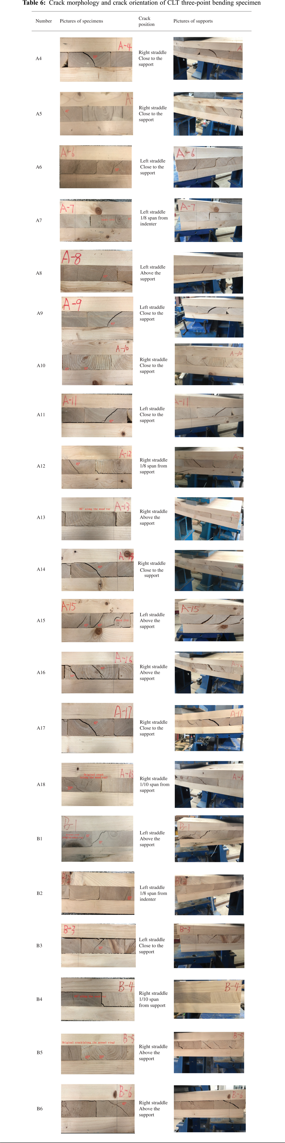
Among the CLT three-point bending specimens (A and B), the specimens where the crack did not penetrate the vertical layer are: A7, A8, A10, A13, B4. The vertical layers of other specimens were all penetrated by cracks. The crack angle and shape are shown in Tab. 6.
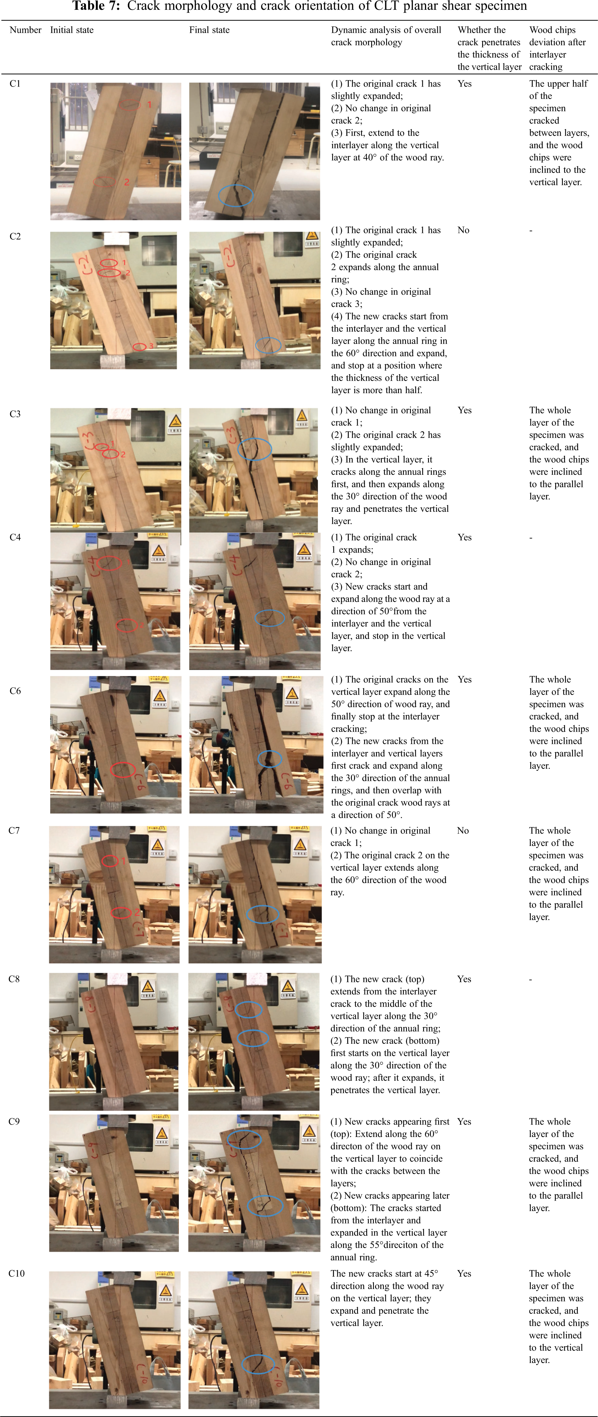
The crack morphology and crack orientation of CLT planar shear specimen (C) are shown in Tab. 7.
Before the test, the cracks that already existed on the vertical layer of the specimen were called original cracks. During the test, the newly generated cracks on the vertical layer of the specimen are called as new cracks (the cracks formed by the expansion of the original cracks are not included).
The total amount of CLT A and B specimens under the three-point bending and CLT C specimens under shearing constituted 30 pieces, of which, 20 original cracks were observed on 11 samples. During the test, the cracks did not expand in 5 places, while in 8 places there was a slight expansion, and in 7 places the expansion of the main cracks caused damage to the surface of the specimen. On the CLT A and B samples under the three-point bending, 26 cracks of the main surface were observed, that is, the expansion of the original cracks to the main surface was in 4 places, while the expansion of the new cracks to the main surface occurred in 22 places.
The CLT A and B specimens under the three-point bending and CLT C specimens under the shearing showed 37 main cracks on the surface. Among them, the expansion of the original crack to the main surface crack was observed in 7 places, and the expansion of new cracks to the main surface crack was observed in 30 places. The expansion of the original cracks and new cracks accounted for 18.9% and 81.1% of the main surface cracks, respectively.
Obviously, the data listed above show that the new crack causes the dominant damage of the specimens, since the original crack load is not as sensitive as the new ones. Wood is different from metal, cracks in the wood cause material damage characteristics.
The statistics and analysis of the cracking morphology and azimuth angle of the CLT vertical layer in this study are only carried out for the main cracking surface that is finally generated in the experiment. Each specimen has one main cracking surface, two and three main cracking surfaces are rare.
The cracking morphology of the wood grain on the cross-section of wood is usually divided into two types: ring shake and heart shake [25]. Ring shake includes circular shake (along the annual ring) and chord cracks (along the tangent direction of annual rings). Heart shakes refer to cracking along the wood ray direction. This study showed that in addition to ring shaking and heart shaking, the cross-section of the vertical CLT layer under mechanical stress has a new crack morphology that is neither ring shake nor heart shake, such as: A15 (45°), A16 (50°), B6 (40°), A18 (30°) and A10 (25°) (Note: the azimuth angle measured from the cracked surface is in brackets) (Fig. 6).
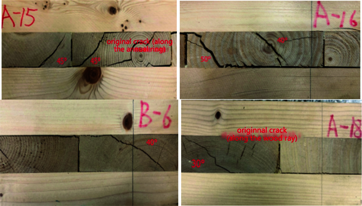
Figure 6: Cracking appearance on a vertical layer that is neither ring shake nor heart shake
4.2.2 Azimuth Angle of the CLT Cracking Surface
The vertical layer of the CLT specimens under three-point bending has the shape of the Chinese character eight in the cracking direction of the left half-span or the right half-span.
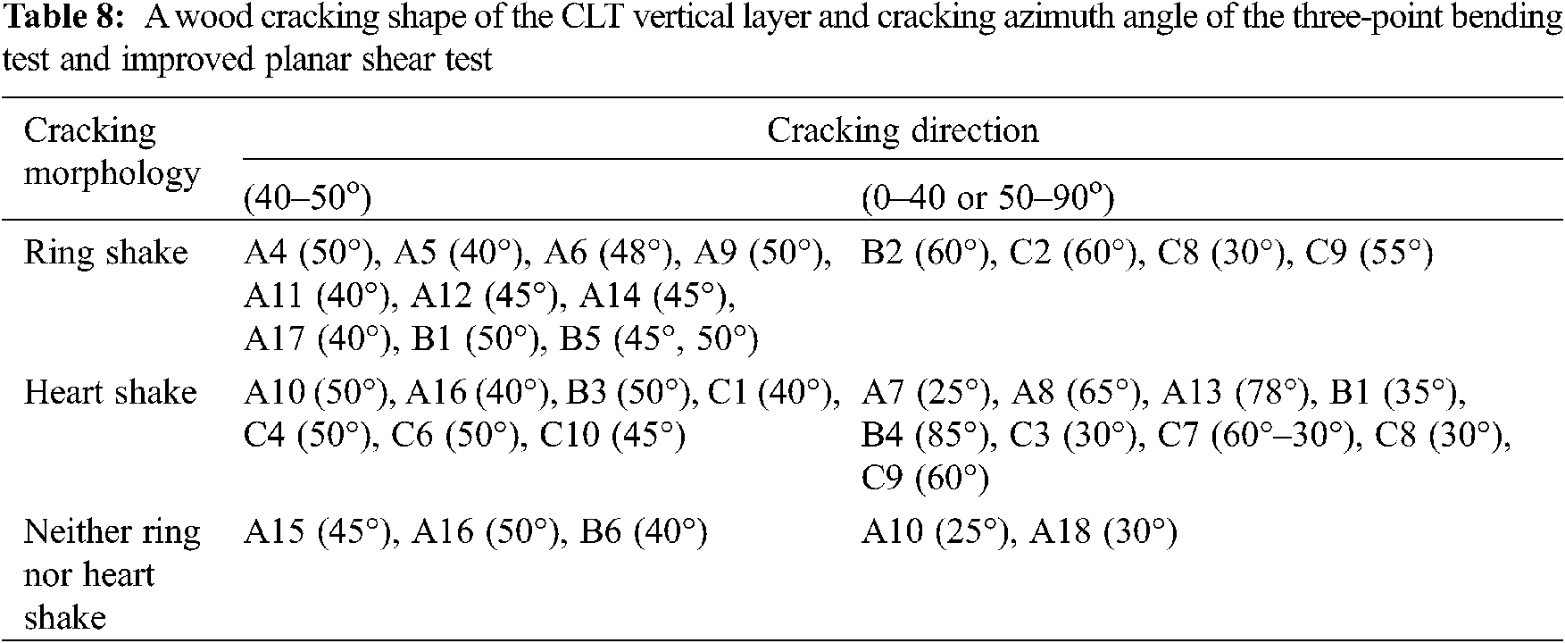
The cracking shape of the vertical layer of the wood and azimuth angle of CLT specimens A and B at three-point bending test and CLT specimen C at the shear test are shown in Tab. 4. For example, A4 (50°) represents the A-series test specimen, the test specimen number is 4, the angle in brackets means that the azimuth angle of the specimen is 50°.
As indicated in Tab. 8, the test specimens with an azimuth angle of cracking surface between 40°–50° and the test specimens with a wood ray of 25°–40° or 50°–65 ° cracked by 63.3% and 23.3%, respectively. The test specimens with angles of the vertical layer cracking in the range of 22.5°–40° or 50°–67.5° are A7 (heart shake, 25°), A8 (heart shake, 65°), A10 (two cracks: heart shake, 50°; 25° neither along the annual ring nor along the wood ray), A18 (along the tangent line of the annual ring-wood ray-neither the annual ring nor the wood ray shows a crack angle of 30° and penetrates through the thickness of the vertical layer), B1 (two cracks: neither along the annual ring nor along the wood ray 45°; 35° wood grain is not clear), B2 (60° blurred annual ring lines), C8 (two cracks, one of which is heart shake 30°), C9 (two cracks: heart shake, 60°; ring shake, 55°).
Through the analysis of the cracking shape of the vertical layer and azimuth angle of the CLT specimen at the three-point bending test, it is found that: ① the vertical layer cracking of the CLT specimen at the three-point bending test has three morphologies: along the wood ray (diameter crack), along the annual ring or the tangent line of the annual ring (ring shake), neither along the ring shake nor along the heart shake. ② The azimuth angle of the CLT specimen’s vertical layer cracking at the three-point bending test is between 40°–50°, a total number is 15 specimens (18 places). There are three types of cracking: ring shake (10 blocks, 12 places), heart shake (2 blocks, 3 places), and neither ring shake nor heart shake (3 blocks, 3 places). ③ The angle of the vertical layer cracking in 8 specimens (8 places) is outside 40°–50°. There are three types of cracking: ring shake (1 block, 1 place), heart shake (5 blocks, 5 places), and neither ring shake nor heart shake (2 blocks, 2 places). ④ The specimens with two cracks are: A10 (50°, 25°), B1 (45°, 35°), B5 (45°, 50°), A16 (40°, 50°); The specimens with three cracks are: A15(The ring shake is 45°; neither the ring shake nor the heart shake is 45°; there is also a crack along the wood ray-annual ring-wood ray.). ⑤ The basic cracking form on the wood cross-section is ring shake and heart shake, and this study found that in addition to these, there are cracking forms that are neither ring shake nor heart shake, such as A15 (45°), B6 (40°), A16 (50°), A10 (25°), A18 (30°). There are 5 pieces in total, accounting for 23.8% of the total number of three-point bending specimens. ⑥ Among 15 CLT specimens A at three-point bending test, the angle of the vertical layer cracking of 12 specimens is between 40°−50°, and 11 blocks crack in the thickness of the vertical layer; The angle of the vertical layer cracking of the CLT specimen A and B at the three-point bending test is between 40°–50°, the number of specimens is 16 pieces, accounting for 76.2% of the total number of three-point bending test specimens. (The cracking angle between 40° and 50° is calculated by block. It means that if there are two cracks with a cracking angle between 40°–50° on a piece of the specimen, it is calculated as one block) ⑦ Different cracking features, such as A6, are also observed on both ends of the vertical layer of the same specimen if the cracking surface runs through the width of the test specimen. The cracking surface of A6 is located on the left half of the three-point bending specimen, and the direction of the cracking surface on the front and back end faces of the vertical layer of the same specimen is in a straight shape of the Chinese character eight.
Through the analysis of the vertical layer cracking shape and azimuth angle of the CLT specimen at the shear test, it is learned that ① the cracking position of the CLT specimen in the vertical layer is not along the shear stress surface, but presents a certain angle between the parallel layer and the vertical layer interface. The cracking shape is ring shake and heart shake, and no cracking shape is found that is neither ring shake nor heart shake. ② Among the 9 pieces of CLT shear specimens, the morphology and azimuth angle of 11 main cracking surfaces are summarized as 4 blocks (4 places) with the azimuth angle of the cracking surface between 40°–50°, accounting for 44.4% of the total number of specimens. There are cracking forms along the wood ray (heart shake) such as C1 (40°), C4 (50°), C6 (50°), C10 (45°). There are 5 blocks (7 places) of the azimuth angle of the cracking surface which is outside 40°–50°, accounting for 55.6% of the total number of specimens. There are cracking forms along the wood ray (heart shake) such as C3 (30°), C7 (60°), C8 (30°), C9 (60°). As well as along the annual ring or the tangent of the annual ring (ring shake) such as C2 (60°), C8 (30°), C9 (55°). Among them, there are 3 specimens that exhibited the expansion from the original crack to the main crack surface such as C3, C6, C7. ③ 9 blocks of CLT specimens at shear test exhibited 12 original cracks, of which 5 places did not expand, 4 places expanded slightly, and 3 places expanded to the main cracking surface. ④ The azimuth angle of the original crack in the C7 specimen is 60°, and it expands along the wood ray (heart shake).
4.2.3 Analysis of a “Shake” Phenomenon in the Load-Displacement Curve
(1) In the three-point bending test, at the point B on the load-displacement curve (Fig. 3) of the A9 specimen a “shake” appears corresponding to the specimen cracking phenomenon, while in the stage of the load drop (CD stage, the displacement is unchanged, the load suddenly decreases) corresponding cracks suddenly increase. Obviously, on the load-displacement curve of the specimen A, there is a commonality between a “shake” and a fall stage corresponding to the cracking and sudden increase (crack expansion) of the specimen such as A17 and B3, respectively. This phenomenon is different from metals (e.g., steel test specimens) because if the metal is subjected to the three-point bending or compact stretching, the specimen cracks on its load-displacement curve, and once it cracks, the load drops directly, so this reflects the orthotropic anisotropic characteristics of the wood. In the video of the three-point bending test, the specimen is found to crack, but there is no corresponding “shake” phenomenon on the load-displacement curve, it may crack inside, which is not visible on the video. But the sound in the video is used as an auxiliary judgment.
The load-displacement curve of the CLT specimen in the improved planar shear test is different from the load-displacement curve of the three-point bending test, there is a slight “shake” of the falling stage (CD stage of C3 in Fig. 7), and a “shake” crack occurs, reflecting the natural characteristics of the wood. The load-displacement curve of the CLT shear test also exhibits a “shake” in many places corresponding to the production of new cracks.
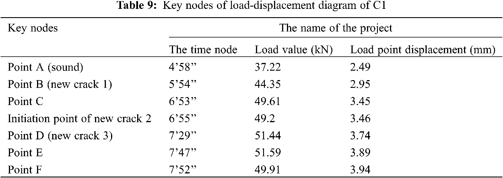
The load-displacement curve of the specimen C1 also shows a “shake” phenomenon several times (Figs. 7A–7D), from B, C, D, from the corresponding time nodes in the vertical layer surface of the specimen a newly formed crack can be observed, as shown in Tab. 9. Although no new cracks formed at a “shake” in the vertical layer surface of the specimen, but a “click” sound can be heard from the issued video, indicating that the internal wood fiber cracks.
(2) The load-displacement curves of the three-point bending test and the improved planar shear test have different degrees of falling segments, which are in line with the characteristics of fracture mechanics theory and wood orthotropy.
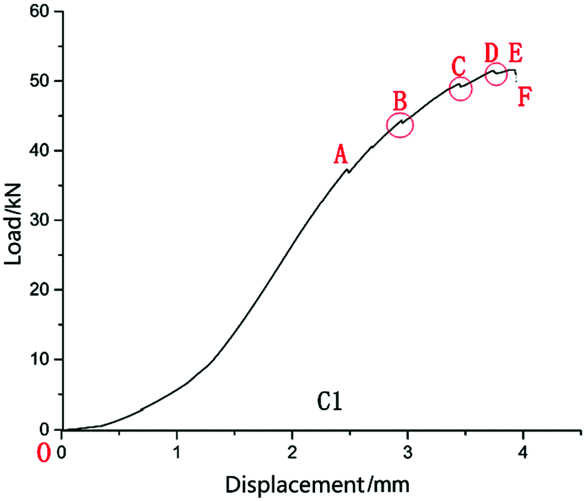
Figure 7: Load displacement curve of CLT shear specimen C1
Obviously, the test breakpoint of the three-point bending test and the improved planar shear test is before or at the initial drop point. A “shake” appears on the load-displacement curve of the three-point bending test and the improved planar shear test, indicating that the test specimen is cracking. On the load-displacement curve, there is a sudden increase in cracks in the three-point bending test, and the sudden increase in cracks in the improved planar shear test specimens is not clear or unclear, reflecting the cracking characteristics in the process of realizing planar shear deformation under two different loading methods. The crack angles on the front and back sides of the test specimen are consistent, such as A17 and B3. Some are not exactly the same, such as A9, which also reflects the orthotropic characteristics of wood.
1. Both the three-point bending test and the improved planar shear test can realize the in-planar shear of the CLT vertical laminate cross-section, which can be used to test the planar shear strength of CLT. The planar shear strength of the hemlock CLT tested by two methods is quite consistent, with a difference of only 5.7% in value.
2. The original cracks and new cracks expanded to the main crack surface account for 18.9% and 81.1% of the total cracking surface, respectively.
3. The vertical layer cracks of CLT specimens under three-point bending have three morphologies: heart shakes, ring shakes, and neither ring shakes nor heart shakes. Among them, CLT specimens A and B have heart shakes and ring shakes on the vertical layers accounting for 76.2% of the total number of specimens, and the cracking morphology with neither ring shakes nor heart shakes accounts for 23.8% of the total number of specimens.
4. The azimuth of the cracking surface of the CLT vertical layer in planar shear is quite consistent with the first principal plane azimuth of the vertical layer of the CLT three-point bending specimen and the shear specimen. The vertical layer of the specimen is shaped like Chinese character eight, in the cracking direction of the left half-span or the right half-span. In this study, 76.2% of the CLT specimens A and B under three-point bending and 44.4% of the CLT specimens C under shearing have the cracking surface of the vertical layer with the azimuth between 40°–50°.
5. Compared with the new cracks, the original cracks are more stable during the loading process, and most of the damage of the specimens is caused by the new cracks.
Funding Statement: The authors received no specific funding for this study.
Conflicts of Interest: The authors declare that they have no conflicts of interest to report regarding the present study.
1. Wimmer, H., Hochhauser, W., Nachbagauer, K. (2020). Refined zigzag theory: An appropriate tool for the analysis of CLT-plates and other shear-elastic timber structures. European Journal of Wood and Wood Products, 78(6), 1125–1135. DOI 10.1007/s00107-020-01586-x. [Google Scholar] [CrossRef]
2. Sandoli, A., Calderoni, B. (2020). The rolling shear influence on the out-of-plane behavior of CLT panels: A comparative analysis. Buildings, 10(3), 42. DOI 10.3390/buildings10030042. [Google Scholar] [CrossRef]
3. Rahman, M. T., Ashraf, M., Ghabraie, K., Subhani, M. (2020). Evaluating timoshenko method for analyzing CLT under out-of-plane loading. Buildings, 10(10), 184. DOI 10.3390/buildings10100184. [Google Scholar] [CrossRef]
4. Wang Z., H., Gao, Z. Z., Wang, Y. L., Cao, Y., Wang, G. G. et al. (2015). A new dynamic testing method for elastic, shear modulus and poisson’s ratio of concrete. Construction and Building Materials, 100, 129–135. DOI 10.1016/j.conbuildmat.2015.09.060. [Google Scholar] [CrossRef]
5. Wang, Z. H., Wang, Y. L., Cao, Y., Wang, Z. (2016). Measurement of shear modulus of materials based on the torsional mode of cantilever plate. Construction and Building Materials, 124, 1059–1071. DOI 10.1016/j.conbuildmat.2016.08.104. [Google Scholar] [CrossRef]
6. Wang, Z. H., Wang, Z., Wang, B. J., Wang, Y. L., Rao, X. et al. (2014). Dynamic testing and evaluation of modulus of elasticity (MOE) of SPF dimension lumber. BioResources, 9(3), 3869–3882. DOI 10.15376/biores.9.3.3869-3882. [Google Scholar] [CrossRef]
7. Sikora, S. K., McPolin, D. O., Harte, A. M. (2016). Effects of the thickness of cross-laminated timber (CLT) panels made from Irish sitka spruce on mechanical performance in bending and shear. Construction and Building Materials, 116(7), 141–150. DOI 10.1016/j.conbuildmat.2016.04.145. [Google Scholar]
8. Gao, Z. X. (2017). Designing, manufacturing and property evaluation of Hemlock CLT (Master Thesis). Nanjing Forestry University, China. [Google Scholar]
9. Li, M. Y., Zhang, S. B., Gong, Y. C., Tian, Z. P., Ren, H. Q. (2021). Gluing techniques on bond performance and mechanical properties of cross-laminated timber (CLT) made from larix kaempferi. Polymers, 13, 733. DOI 10.3390/polym13050733. [Google Scholar] [CrossRef]
10. Miyamoto, B., Bechle, N. J., Rammer, D. R., Zelinka, S. L. (2021). A small-scale test to examine heat delamination in cross laminated timber (CLT). Forests, 12(2), 232. DOI 10.3390/f12020232. [Google Scholar] [CrossRef]
11. Turesson, J., Berg, S., Bjornfot, A., Ekevad, M. (2020). Shear modulus analysis of cross-laminated timber using picture frame tests and finite element simulations. Materials and Structures, 53(4), 112. DOI 10.1617/s11527-020-01545-1. [Google Scholar] [CrossRef]
12. He, M. J., Sun, X. F., Li, Z., Feng, W. (2020). Bending, shear, and compressive properties of three-and five-layer cross-laminated timber fabricated with black spruce. Journal of Wood Science, 66(1), 38. [Google Scholar]
13. Huber, J. A. J., Ekevad, M., Girhammar, U. A., Berg, S. (2020). Finite element analysis of alternative load paths in a platform-framed CLT building. Proceedings of the Institution of Civil Engineers–Structures and Buildings, 173(5), 379–390. DOI 10.1680/jstbu.19.00136. [Google Scholar] [CrossRef]
14. Lu, Y., Xie, W. B., Wang, Z., Gao, Z. Z. (2018). Shear stress and interlaminar shear strength tests of cross-laminated timber beams. Bioresources, 13(3), 5343–5359. DOI 10.15376/biores.13.3.5343-5359. [Google Scholar]
15. Wang, Z. H., Ghanem, R. (2021). An extended polynomial chaos expansion for PDF characterization and variation with aleatory and epistemic uncertainties. Computer Methods in Applied Mechanics and Engineering, 382, 113854. DOI 10.1016/j.cma.2021.113854. [Google Scholar] [CrossRef]
16. ASTM Standard D2718 (2011). Standard Test Methods for Structural Panels in Planer Shear (Rolling Shear). West Conshohocken, PA: ASTM International. [Google Scholar]
17. Lu, Y. (2020). Research on test method for plane shear strength of CLT and analysis of its failure mechanism. (Master Thesis). Nanjing Forestry University, China. [Google Scholar]
18. Li, M. H. (2017). Evaluating rolling shear strength properties of cross-laminated timber by short-span bending tests and modified planar shear tests. The Japan Wood Research Society, 63, 331–337. DOI 10.1007/s10086-017-1631-6. [Google Scholar] [CrossRef]
19. Ehrhart, T., Brandner, R. (2018). Rolling shear: Test configurations and properties of some european soft-and hardwood species. Engineering Structures, 172, 554–572. DOI 10.1016/j.engstruct.2018.05.118. [Google Scholar] [CrossRef]
20. APA–The Engineered Wood Association (2012). Standard for Performance-Rated Cross-Laminated Timber ANSI/APA PRG 320. Tacoma, WA, USA: APA-The Engineered Wood Association. [Google Scholar]
21. Ggnon, S., Bilek, E. M., Podsto, L. (2012). CLT handbook: Cross-laminated timber. USA: FPInnovation. [Google Scholar]
22. EN Standard 408 (2003). Timber Structures-Structural Timber and Glued Laminated Timber-Determination of Some Physical and Mechanical Properties. Brussels, Belgium: European Committee for Standardisation. [Google Scholar]
23. Gong, M., Tu, D., Li, L. (2015). Planar shear of hardwood cross layer in hybrid cross laminated timber. 5th International Scientific Conference on Hardwood Processing, Quebec City, Canada. [Google Scholar]
24. Wang, Z., Lu, Y., Xie, W. B., Gao, Z. Z., Ding, Y. W. et al. (2019). Cross laminated timber (CLT) beam shear stress analysis and inter-layer shear strength test. Forestry Science, 55(2), 152–158. DOI 10.11707/j.1001-7488.20190216. [Google Scholar] [CrossRef]
25. Yin, S. C. (1996). Wood science. China: China Forestry Publishing House. [Google Scholar]
 | This work is licensed under a Creative Commons Attribution 4.0 International License, which permits unrestricted use, distribution, and reproduction in any medium, provided the original work is properly cited. |