| Journal of Renewable Materials |
DOI: 10.32604/jrm.2022.017373
ARTICLE
Experimental Study on the Bending Properties of Grouting Butt Joints Reinforced by Steel Plate Embedded in Bamboo Tube
College of Civil Engineering and Architecture, Zhejiang University, Hangzhou, 310058, China
*Corresponding Author: Xin Zhuo. Email: zhuoxin@zju.edu.cn
Received: 06 May 2021; Accepted: 17 June 2021
Abstract: The construction of grouting butt joints of bamboo tubes is simple and efficient. However, when the joint is bent, the low tensile strength of the mortar easily leads to cracking of the mortar prior to the failure of the bamboo tube. In this paper, a comparative test of the bending capacity was performed on grouting butt joints reinforced by nonperforated, fully perforated, and semiperforated steel plates embedded in bamboo tubes to obtain the load-displacement curves and ultimate bearing capacity of various specimens. The strengthening effect of CFRP pasted on bamboo tubes was also studied. The results show that the opening at the end of the steel plate is beneficial to resist the slip between the mortar and steel plate, while the complete section in the middle of the steel plate is conducive to making full use of the tensile strength of the steel plate. Therefore, it is best to insert the semiperforated steel plate with openings in the end and without openings in the middle into the mortar to enhance the bending properties of the grouting butt joint, which can make the failure mode of the joint change from brittle failure of mortar to ductile compression failure of bamboo tube. In addition, pasting CFRP sheets on the external wall of the bamboo tube helps to reduce the tensile stress of the mortar, while increasing the width of the steel plate can increase the bending moment of inertia of the mixture of the steel plate and mortar. These two complementary measures are very effective in delaying the cracking of the bamboo tube and improving the bending capacity of the joint.
Keywords: Bamboo tube; butt joint; grouting connection; perforated steel plate; enhancement measure
Bamboo is the most important nontimber renewable forest product in the world, possessing a short growth cycle and strong carbon sequestration capacity [1]. Compared with traditional building materials such as concrete and steel, bamboo has the advantages of low energy consumption [2] and natural degradation, which is of great significance to economic development, energy conservation and environmental protection. Bamboo tube has good axial mechanical properties [3,4] and bending properties [5,6]. A large number of studies on the performance of bamboo as a renewable building material [7] and the successful construction of modern raw bamboo buildings [8,9] proves the feasibility of bamboo tubes as structural materials. For the raw bamboo buildings, the joint is the key of load transfer, and the connection in raw bamboo buildings has always been a major problem in the popularization and application of bamboo. Hong et al. [10] summarized two traditional connection forms and four modern connection forms of bamboo structural joints, which provided an important reference for engineering designs and applications. The geometric non-uniformity of bamboo tube makes it difficult for most of the joints [11–15] of existing bamboo tube spatial structure to be standardized. However, the grouting connection is not only compatible with the natural defects of bamboo tube, but also retains the natural appearance of bamboo, which is an ideal connection form for the joints of bamboo tube spatial structure.
Because of the taper geometry, the actual usable length of each bamboo culm is very limited, so the bamboo tube of the large-span structure needs to be lengthened axially. Rui [16] conducted an experimental study on the bending properties of grouting butt joints of bamboo tubes. It was a single-point loading test with concentrated force in the middle of a simply supported beam and the distance between the supports was 600 mm. Except for the cement mortar, there were no steel members embedded inside the specimens. The test results showed that the connection strength of the joint with a two-month curing period was very low and the average ultimate load was only 0.82 kN. The failure mode of the joint was similar to that of the unreinforced beam, which belongs to brittle failure (Fig. 1). Morisco [17] proposed a steel plate butt joint, the outer surface of which was connected by a steel plate and bolt, and the cavity of the bamboo tube was reinforced by injecting cement mortar. The joint had good strength and ductility, but the exposed steel plate had poor aesthetics (Fig. 2).
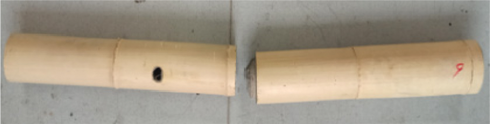
Figure 1: Grouting joint [16]
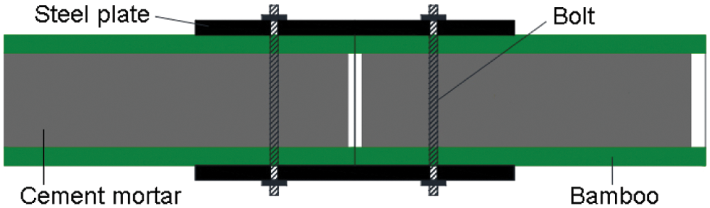
Figure 2: Steel plate joint [17]
Fu et al. [18] proposed a sleeve-cement butt joint, in which the internal wall of the bamboo cavity was roughened, the steel sleeve embedded in the bamboo cavity was perforated and fixed with pin, the cement mortar was injected between the sleeve and the bamboo tube, and the outer surface of the bamboo tube was laterally restrained by a steel ring. The connection strength was provided by the friction force between the mortar and internal wall of the bamboo and the mechanical bite force between the mortar and sleeve. The tensile and compressive test results showed that the joint had good axial performance, but the bending performance was not clear, and the bond looseness caused by the difference in shrinkage rate between cement mortar and bamboo had a great influence on the axial performance of the joint (Fig. 3).
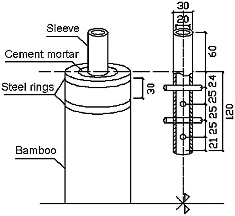
Figure 3: Sleeve-cement joint [18]
Inoue et al. [19] filled the bamboo cavity with split bamboo strips and a bamboo connector which is developed for timber connection. Then, the bamboo strips, bamboo connector and bamboo tube were bonded as a whole with urethane adhesive. The joint can effectively avoid the interface separation caused by the difference of shrinkage and expansion rate of different materials and has a good appearance, but the fabrication of the joint was cumbersome, and the construction efficiency was low (Fig. 4). Inoue et al. [19] also proposed a butt joint composed of a steel ring and cup with plaster. The steel rings were connected by bolts. The bearing capacity of the joint depends on the friction between the steel rings and the surface of bamboo, but the friction was greatly affected by human factors (Fig. 5).

Figure 4: Joint filled with bamboo strips [19]

Figure 5: Joint filled with plaster [19]
As a potential enhancement measure to enhance the stiffness and strength of bamboo, carbon fiber-reinforced polymer (CFRP) is an alternative to metal used to reinforce bamboo structures [20–22]. Awaludin et al. [23] improved the mechanical properties of bolted joints under parallel loads by pasting FRP sheets. The test results show that the wrapping effect of FRP sheets significantly improves the slip modulus and lateral bearing capacity of the joints (Fig. 6).

Figure 6: Awaludin jointing method [23]
Zhuo et al. [8] proposed the bamboo tube bundle spatial lattice structure system, which discretizes any complex surface into a combination of many simple triangular units made with bamboo tubes, as shown in Fig. 7a. Each triangular unit is made up of three bamboo tubes, which are connected end to end and grouted in the cavity of the joint area, as shown in Fig. 7b. The structure and location of the steel plate embedded in the joint are shown in Fig. 7c. It should be pointed out that engineering applications have shown that the bamboo tube triangle is easy to crack at the corner under out-of-plane load, as shown in Fig. 7d, because the bending moment is more significant in the strong axis direction and less in the weak axis direction. The steel plate is used because of its great flexural strength in the strong axis direction and easiness to bend in the weak axis direction, which makes the mass-produce of bamboo tube triangle with any angle easy and convenient. However, the best structural form of steel plate needs to be further explored through experiments. In this paper, the bending properties of grouting butt joints reinforced by nonperforated steel plates, semiperforated steel plates and fully perforated steel plates and the reinforcement effect of CFRP sheets and iron wires are studied by contrast experiments.

Figure 7: Bamboo tube bundle spatial lattice structure system (a) Practical application (b) Bamboo tube triangle (c) Grouting butt joint (d) Failure mode of the joint
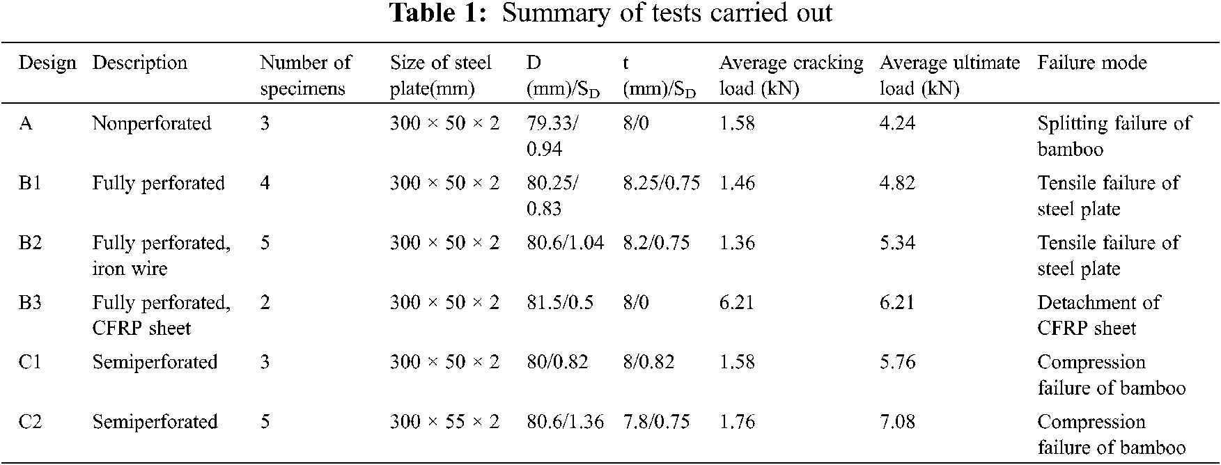
The internal structure of the specimen is shown in Fig. 8. Two bamboo tubes are connected with cement mortar, and the steel plate is embedded in the middle cavity. Six control groups were set in the test, as shown in Table 1.

Figure 8: Details of specimen section
Phyllostachys pubescens, commonly known as moso bamboo, was grown in Anji County, Huzhou City, Zhejiang Province, China for four years. After natural air drying, the moisture content of the culms was less than 12%, and the average external diameter D and wall thickness t of the culm are shown in Table 1. Standard 32.5 grade ordinary Portland cement and medium sand with a moisture content of 2% and bulk density of 1540 kg/m3 were selected here, and the cement mortar infill consisted of an average mix ratio of 2.5 parts cement, 1 part sand, and 1.2 parts water by mass [14]. The geometric dimensions of the Q235 steel plate used are shown in Table 1, and the opening of the steel plate and winding of the iron wire are shown in Fig. 9a. The iron wire was 16# 1.6 mm with a tensile strength of 47 MPa. The CFRP sheet was a 300 g high strength grade I unidirectional carbon fiber cloth with a tensile strength of 3450.4 MPa, tensile modulus of elasticity of 2.4105 GPa and elongation of 1.74%. The blending ratio of epoxy resin adhesive was 1:1, the viscosity was 40000–45000 CPS, and the shear strength was more than 12 MPa.
The length of the bamboo tube is 300 mm, and the length of the specimen is 600 mm. The grouting length in the middle of the specimen is controlled to be 400–450 mm by using the slub of the bamboo tube at the end. The steel plate is placed in the middle, and the bonding range of the CFRP sheet is 300 mm × 100 mm at the tensile side of the middle of the specimen, as shown in Fig. 9b. The curing time of the specimen is 28 days. In the manufacturing process of the joint, we grout layer by layer from top to bottom, and stir each layer for five minutes to minimize the initial defects of the mortar, as shown in Fig. 10. In addition, we ensure that the manufacturing process of each joint is consistent to reduce the difference between groups.

Figure 9: Materials (a) Steel plates (b) CFRP sheet

Figure 10: Manufacturing process (a) Cutting of bamboo tube (b) Embedding of steel plate (c) Grouting
2.2 Test Setup and Measurements
The test loading equipment was a UTM5000 electronic universal testing machine, which was produced by Shenzhen Suns Technology Co., Ltd., Shenzhen, China. The maximum load is 100 kN, the displacement rate range is 0.001–500 mm/min, and the accuracy of the displacement rate is within 0.5% of the setting value.
It is a single-point loading test with concentrated force in the middle of a simply supported beam (Fig. 11). The distance between the supports is 400 mm, and the displacement loading rate is 1 mm/min. The load and displacement data are collected by a computer equipped with loading equipment. The specimen is placed in the middle, and the deformation is recorded after a 0.2 kN preload is applied. The average cracking load and average ultimate load of each group of specimens are shown in Table 1.

Figure 11: Test setup
3 Test Process and Results Analysis
The load-displacement curves of each group of specimens are shown in Fig. 12, and the marked points on the curves are the ultimate load and displacement of each specimen.
In Group A, the load-displacement curve in the early stage of loading presents a linear characteristic, and the crack in the middle of the mortar leads to a decrease in the stiffness of the specimen and slope of the curve. When the tensile stress at the end of the mortar reaches the splitting tensile strength, the mortar splits, and the curve decreases obviously, corresponding to “burr 1” on the curve. The steel plate at the splitting end of the mortar contacts the internal wall of the bamboo tube, and the curve continues to rise until the steel plate splits the bamboo tube and the specimen is destroyed.
In Groups B1 and B2, the load-displacement curve presents a linear characteristic at the early stage of loading, and the crack in the middle of the mortar leads to a decrease in the stiffness of the specimen and slope of the curve. There are no obvious burrs on the curve before the specimen is damaged. With the sound of “Bang”, the bottom edge of the opening of the steel plate is broken, the specimen is damaged, and the curve drops sharply. The reason why the curve of specimen B1–1 fluctuates greatly in the early stage is that the bamboo tube is elliptical and the preset loading direction does not coincide with the center of gravity of the specimen, which leads to the deviation of the specimen position in the loading process.
In Group B3, the slope of the load-displacement curve before failure remains unchanged, and the straight-line segments of the two specimens basically coincide. Among them, burr 2 of the straight-line segment of specimen B3–2 indicates that the bonding surface between the CFRP sheet and bamboo tube is separated due to the tensile stress reaching the bonding strength. With the sound of “Si”, the curve decreases sharply, specimen B3–1 reaches the ultimate load, the CFRP sheet is completely separated from the external wall of the bamboo tube, the tensile stress is borne by the steel plate and mortar, and most of the mortar cracks due to the sudden increase in stress. The CFRP sheet of specimen B3–2 is not completely separated from the external wall of the bamboo tube, a small part of the mortar cracks, and the tensile stress is borne by the mixture of the steel plate and mortar and the CFRP sheet. With the increase in tensile strain at the bottom edge of the opening of the steel plate, the curve increases slightly. After the bottom edge of the opening of the steel plate was broken, the CFRP sheet and bamboo tube of the two specimens were completely separated, specimen B3–2 reached the ultimate load, and the specimens were completely destroyed. The ultimate bearing capacity of specimen B3–2 and specimen B3–1 is almost the same, which indicates that the ultimate bearing capacity will be reached once the CFRP sheet is detached.
In Groups C1 and C2, the load-displacement curve presents a linear characteristic, and the crack in the middle of the mortar leads to a decrease in the stiffness of the specimen and slope of the curve. When the hoop tensile stress on the outer surface of the compressed side of the bamboo tube reaches the hoop tensile strength, the bamboo tube cracks, corresponding to “burr 3” on the curve. For specimens C1–1, C1–2, C2–1, C2–2, C2–3 and C2–5, when the load reaches approximately 70% of the ultimate bearing capacity, the first crack appears on the outer surface of the compression side of the bamboo tube. When the load reaches approximately 95% of the ultimate bearing capacity, the second crack appears on the outer surface of the compressed side of the bamboo tube. When the load reaches 100% of the ultimate bearing capacity, two cracks run through the bamboo tube along the wall thickness direction, and the specimen is destroyed. For specimens C1–3 and C2–4, when the load reaches approximately 95% of the ultimate bearing capacity, two cracks appear on the outer surface of the compression side of the bamboo tube at the same time. When the load reaches 100% of the ultimate bearing capacity, the crack runs through the bamboo tube along the wall thickness direction, and the specimen is destroyed. In addition, the cement mortar at the opening of the steel plate shows shear failure.
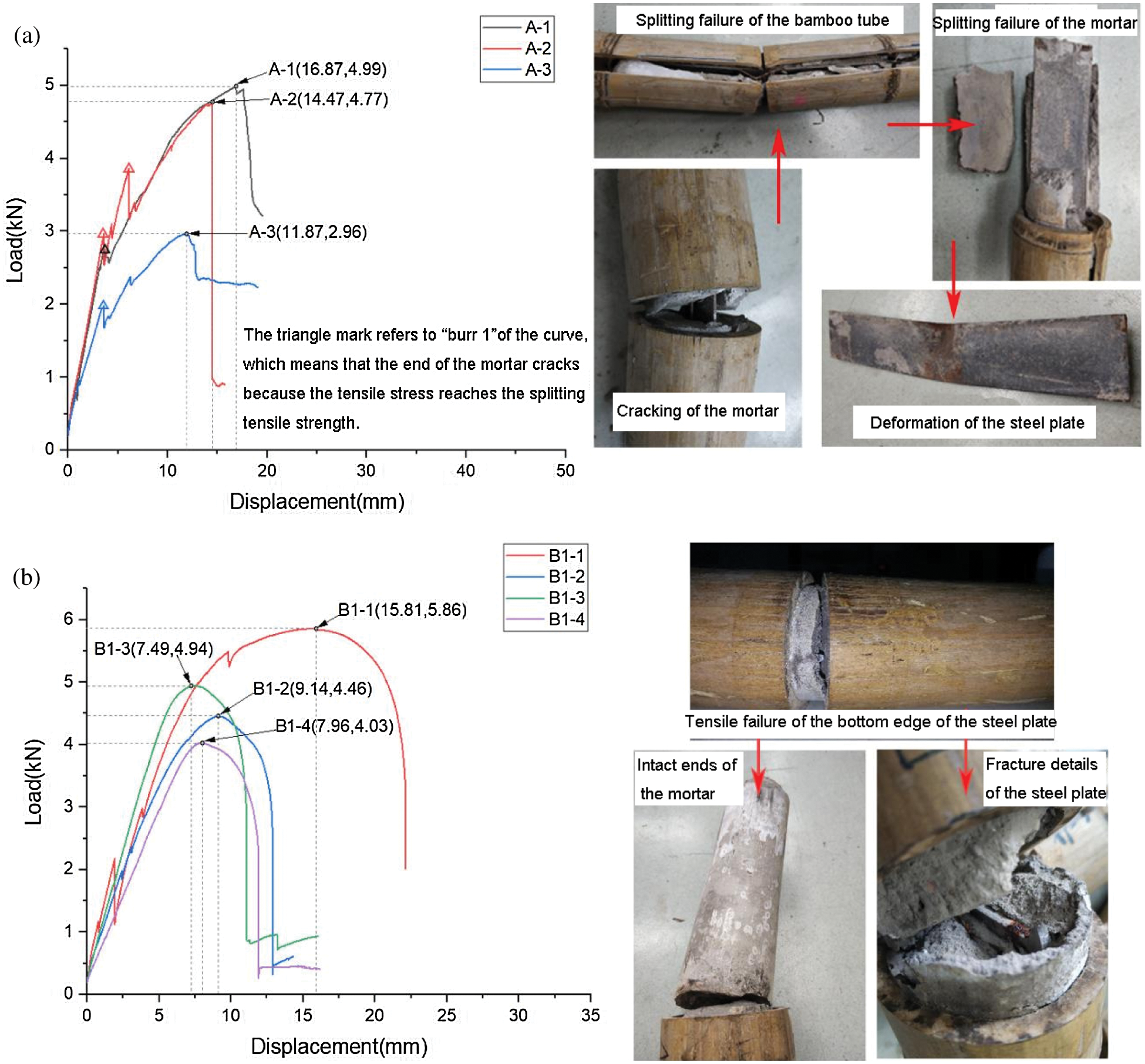
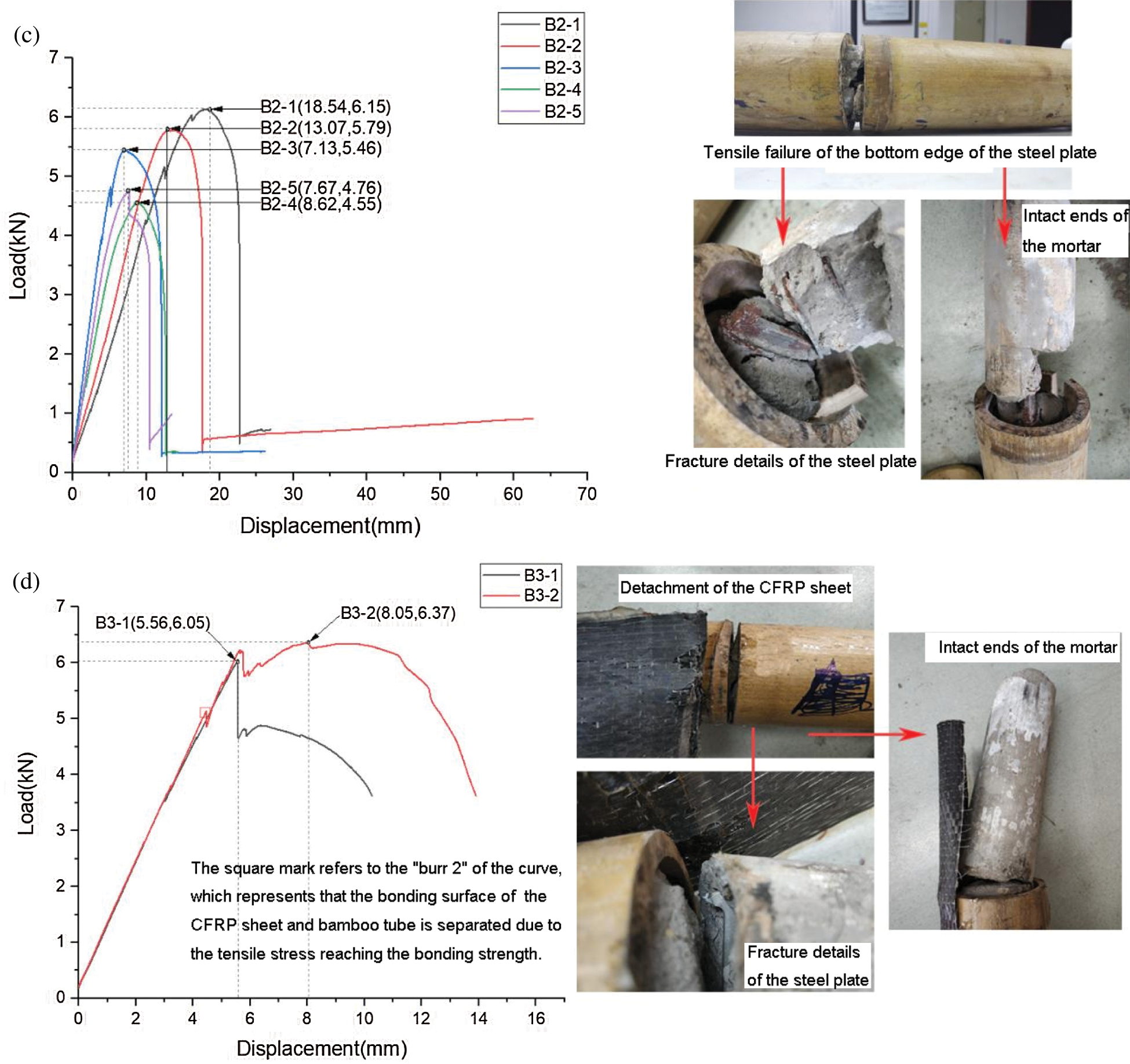
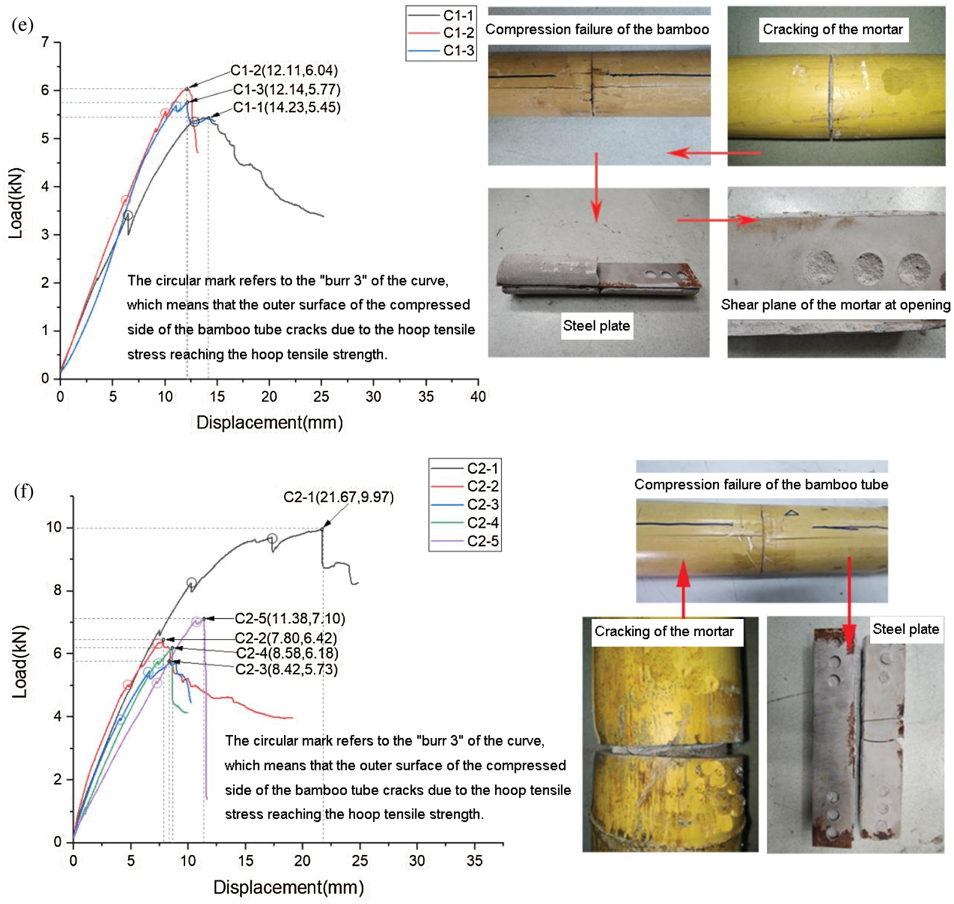
Figure 12: Load-displacement curves (a) Group A (b) Group B1 (c) Group B2 (d) Group B3 (e) Group C1 (f) Group C2
3.2 Comparison of Bearing Capacity and Failure Mode
The comparison of bearing capacity and failure mode is as follows:
(1) Comparative analysis of Groups A, B1 and C1: the difference among the three groups is the form of opening. 1) The average ultimate bearing capacity of Group B1 is 12.7% higher than that of Group A. The opening of the steel plate improves the bearing capacity of the joint, but the failure modes of the two groups are quite different. In Group A, the bonding force between the end of the steel plate and the cement mortar is too small, which is not enough to limit the end of the steel plate to tilt up. As a result, the steel plate has a greater force on the cement mortar first and then on the bamboo tube, and finally, the bamboo tube splits. The steel plate of Group B1 is drilled evenly along the length direction to ensure that the end of the steel sheet does not slip with the cement mortar. However, the diameter of the opening is too large, and the middle section is too small, which leads to tensile failure of the bottom edge of the steel plate prior to the failure of the bamboo tube. 2) The steel plate of Group C1 combines the advantages of Groups A and B1. The opening at the end of the semiperforated steel plate is beneficial to the slip resistance between the mortar and steel plate, and the complete section in the middle of the semiperforated steel plate is beneficial to improving the tensile bearing capacity of the steel plate. The average ultimate bearing capacity of Group C1 is 35.8% higher than that of Group A and 19.5% higher than that of Group B. The failure mode of Group C1 is compression failure of the bamboo tube, which makes full use of the axial strength of the bamboo tube and shows the characteristics of ductile failure. A semiperforated steel plate is the best structural form among the three experimental schemes in this experiment, and the size, distribution and number of openings are worth further optimization in the future.
(2) Comparative analysis of groups B1–B3: the difference among the three groups is the additional reinforcement material. The average ultimate bearing capacity of Group B2 is 6.01% higher than that of Group B1. The failure modes of the three groups are similar, and the effect of winding iron wire on the bearing capacity of the grouting butt joint is not obvious. The average ultimate bearing capacity of Group B3 is 28.8% higher than that of Group B1 because the tensile stress of the mortar is greatly reduced by the CFRP sheet. The stress of the CFRP sheet is far from its tensile strength when it is detached. The bearing capacity of the specimens depends on the bond strength between the CFRP sheet and bamboo tube. The results show that the externally pasted CFRP sheet is very effective in improving the bearing capacity of the grouting butt joint, and the improvement of the bond strength between the CFRP sheet and bamboo tube is worthy of further study in the future.
(3) Comparative analysis of Groups C1 and C2: the difference between the two groups is the width of the steel plate. The average cracking load and the average ultimate bearing capacity of Group C2 are 11.4% and 22.9% higher than those of Group C1, respectively. The failure mode of the two groups of specimens is the compression failure of the bamboo tube, which belongs to ductile failure. The results show that increasing the width of the steel plate can increase the bending moment of inertia of the mixture of steel plate and mortar, which is helpful to delay the cracking of the grouting butt joint and improve the bearing capacity. In addition, the average cracking load and the average ultimate bearing capacity of Group C2 are 2.1 times and 8.6 times those of the pure grouting butt joint [16], respectively.
The structure of the grouting butt joint of the bamboo tube is simple, the construction efficiency is high, and the appearance of the joint is natural and smooth after a steel plate is inserted into the joint. The test results show that the bearing capacity of the grouting butt joint of the bamboo tube can be obviously enhanced by adding a semiperforated steel plate inside, pasting a CFRP sheet on the external wall and increasing the width of the steel plate.
Funding Statement: The authors are grateful for the financial support of the National Key Research and Development Program of China (2017YFC0703500).
Conflicts of Interest: The authors declare that they have no conflicts of interest to report regarding the present study.
1. Gu, L., Wu, W. G., Ji, W., Zhou, M. J., Xu, L. et al. (2019). Evaluating the performance of bamboo forests managed for carbon sequestration and other co-benefits in Suichang and Anji. China Forest Policy and Economics, 106(6), 1–10. DOI 10.1016/j.forpol.2019.101947. [Google Scholar] [CrossRef]
2. Vengala, J. (2020). Comparison of embodied energy in different bamboo-based houses. Lecture Notes in Civil Engineering, 68, 197–208. DOI 10.1007/978-981-15-3361-7. [Google Scholar] [CrossRef]
3. Li, H. T., Qiu, Z. Y., Wu, G., Wei, D. D., Lorenzo, R. et al. (2019). Compression behaviors of parallel bamboo strand lumber under static loading. Journal of Renewable Materials, 7(7), 583–600. DOI 10.32604/jrm.2019.07592. [Google Scholar] [CrossRef]
4. Chung, K. F., Yu, W. K. (2002). Mechanical properties of structural bamboo for bamboo scaffoldings. Engineering Structures, 24(4), 429–442. DOI 10.1016/S0141-0296(01)00110-9. [Google Scholar] [CrossRef]
5. Tian, L. M., Wei, J. P., Hao, J. P., Wang, Q. S. (2021). Characterization of the flexural behavior of bamboo beams. Journal of Renewable Materials, 9(9), 1571–1597. DOI 10.32604/jrm.2021.015166. [Google Scholar] [CrossRef]
6. Li, H. T., Zhang, H. Z., Qiu, Z. Y., Su, J. W., Wei, D. D. et al. (2020). Mechanical properties and stress strain relationship models for bamboo scrimber. Journal of Renewable Materials, 8(1), 13–27. DOI 10.32604/jrm.2020.09341. [Google Scholar] [CrossRef]
7. Shu, B. Q., Xiao, Z. P., Hong, L., Zhang, S. J., Li, C. et al. (2020). Review on the application of bamboo-based materials in construction engineering. Journal of Renewable Materials, 8(10), 1215–1242. DOI 10.32604/jrm.2020.011263. [Google Scholar] [CrossRef]
8. Zhuo, X., Dong, S. L. (2021). Bamboo tube bundle spatial lattice structure system and construction technology. Spatial Structure, 27(1), 3–8. DOI 10.13849/j.issn.1006-6578.2021.01.003. [Google Scholar] [CrossRef]
9. Shao, C. Z., Xiong, J. F., Luo, Z., Jin, Y. Z., Ma, J. et al. (2019). Design on large-span bamboo structure of INBAR pavilion of international horticultural exhibition 2019, Beijing, China. Building Structure, 49(17), 43–50. DOI 10.19701/j.jzjg.2019.17.009. [Google Scholar] [CrossRef]
10. Hong, C. K., Li, H. T., Lorenzo, R., Wu, G., Corbi, H. et al. (2019). Review on connections for original bamboo structures. Journal of Renewable Materials, 7(8), 713–730. DOI 10.32604/jrm.2019.07647. [Google Scholar] [CrossRef]
11. Tan, G. Y., Yang, L. (2014). Tectonics of Bamboo. Nanjing: Southeast University Press. [Google Scholar]
12. Morán, R., García, J. J. (2019). Bamboo joints with steel clamps capable of transmitting moment. Construction and Building Materials, 216(1), 249–260. DOI 10.1016/j.conbuildmat.2019.05.025. [Google Scholar] [CrossRef]
13. Zhang, N., Bai, W. F. (2008). Analyzing and improving the construction of bamboo house node. Science Technology and Engineering, 8(18), 5318–5322. DOI 10.3969/j.issn.1671-1815.2008.18.048. [Google Scholar] [CrossRef]
14. Paraskeva, T., Pradhan, N. P. N., Stoura, C. D., Dimitrakopoulos, E. G. (2019). Monotonic loading testing and characterization of new multi-full-culm bamboo to steel connections. Construction and Building Materials, 201, 473–483. DOI 10.1016/j.conbuildmat.2018.12.198. [Google Scholar] [CrossRef]
15. Albermani, F., Goh, G. Y., Chan, S. L. (2007). Lightweight bamboo double layer grid system. Engineering Structures, 29(7), 1499–1506. DOI 10.1016/j.engstruct.2006.09.003. [Google Scholar] [CrossRef]
16. Rui, G. B. (2020). Experimental study on mechanics performance and numerical simulation of Bamboo Tube (Master Thesis). Zhejiang University, Hangzhou, China. [Google Scholar]
17. Morisco, R. B. (1999). Rekayasa Bambu, Nafiri Offset. Yogyakarta. [Google Scholar]
18. Fu, Y. G., Wang, M. Y., Ge, H. B., Li, L. (2012). Experimental study of mechanical properties of bamboo’s joints under tension and compression load. Advanced Materials Research, 450, 749–755. DOI 10.4028/www.scientific.net/AMR.450-451.749. [Google Scholar] [CrossRef]
19. Inoue, M., Nakahara, M., Tanaka, K., Adachi, H., Imabayashi, M. et al. (2004). Development of connecting method for natural round bamboo. Proceeding of World Conference on Timber EngineeringLahti. [Google Scholar]
20. Wu, X. Z., Huang, X. Y., Li, X. J., Wu, Y. Q. (2019). Flexural performance of CFRP-bamboo scrimber composite beams. Journal of Renewable Materials, 7(12), 1295–1307. DOI 10.32604/jrm.2019.07839. [Google Scholar] [CrossRef]
21. Zhou, A. P., Liu, R., Shen, Y. R. (2017). Experiment study on ultimate load-bearing capacity of carbon fiber reinforced polymer reinforced parallel bamboo beam. Journal of Forestry Engineering, 2(3), 137–142. DOI 10.13360/j.issn.2096-1359.2017.03.022. [Google Scholar] [CrossRef]
22. Wei, Y., Ji, X., Duan, M., Li, G. (2017). Flexural performance of bamboo scrimber beams strengthened with fiber-reinforced polymer. Construction and Building Materials, 142(2), 66–82. DOI 10.1016/j.conbuildmat.2017.03.054. [Google Scholar] [CrossRef]
23. Awaludin, A., Andriani, V. (2014). Bolted bamboo joints reinforced with fibers. Procedia Engineering, 95(1), 15–21. DOI 10.1016/j.proeng.2014.12.160. [Google Scholar] [CrossRef]
 | This work is licensed under a Creative Commons Attribution 4.0 International License, which permits unrestricted use, distribution, and reproduction in any medium, provided the original work is properly cited. |