| Journal of Renewable Materials |
DOI: 10.32604/jrm.2022.018803
ARTICLE
Numerical Analysis of Conjugated Heat and Mass Transfer of Helical Hollow Fiber Membrane Tube Bank for Seawater Distillation
1Guangzhou Institute of Energy Conversion, Chinese Academy of Sciences, Guangzhou, 510640, China
2Dongguan University of Technology, Dongguan, 523808, China
3Southern Marine Science and Engineering Guangdong Laboratory (Guangzhou), Guangzhou, 511458, China
*Corresponding Authors: Lisheng Deng. Email: dengls@ms.giec.ac.cn; Jiechao Chen. Email: chenjc@dgut.edu.cn
Received: 18 August 2021; Accepted: 22 October 2021
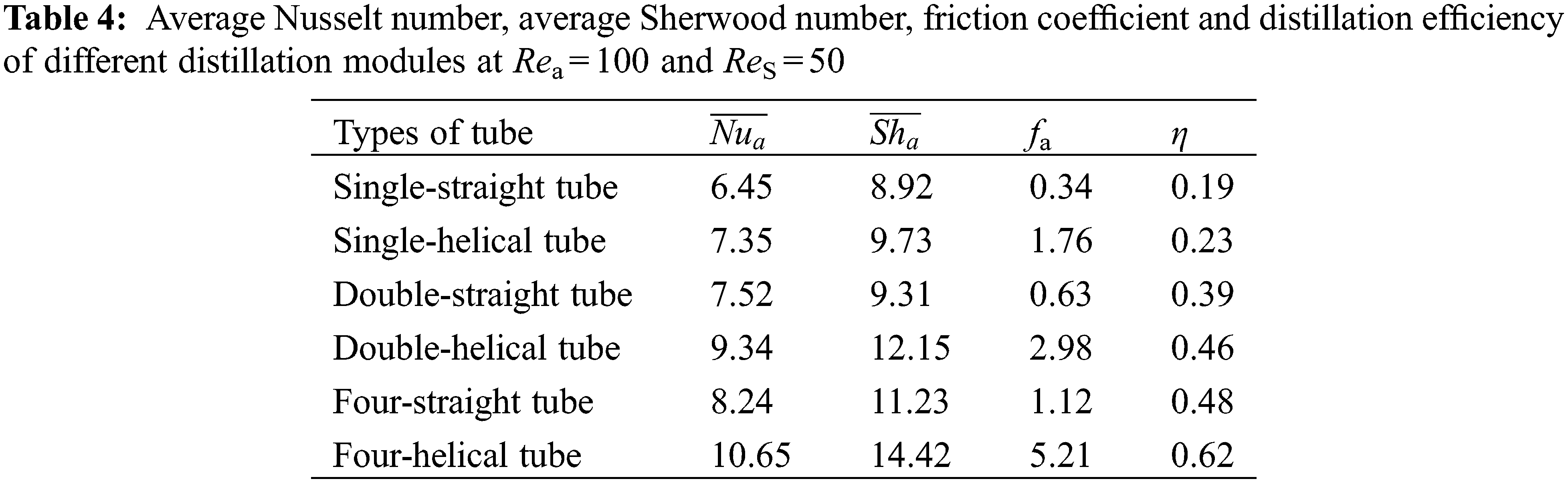
Abstract: A numerical study on the conjugated heat-mass transfer of helical hollow fiber membrane tube bank (HFMTB) for seawater desalination was carried out. Physical and mathematical models of fluid flow, temperature and humidity distribution were constructed to investigate the influences of flow type, Reynolds number, and temperature on the conjugated heat-mass transfer performance of hollow fibers in the distillation membrane module. The conjugated heat-mass transfer characteristics of HFMTB were discussed by utilizing the friction coefficient, Nusselt number (Nu), and Sherwood number (Sh). Results demonstrate that a distillation efficiency enhancement of 29% compared to the straight HFMTB has been detected for four-helical HFMTB configuration, though the friction coefficient of such a module is about 4 times of their straight counterparts. The values of average Nu and Sh numbers are increasing with tube number, which improves distillation efficiency. The effect of flow type has been studied by employing the upstream and downstream flows to the double-helical HFMTB, demonstrating upstream flow type is more conducive to the heat-mass transfer process. Both the outlet air humidity (ω) and distillation efficiency (η) decrease with the air-side Reynolds number (Rea) and inlet air temperature in the helical HFMTB while increasing with the solution-side Reynolds number (ReS) and inlet solution temperature. Overall, the obtained results indicate that helical HFMTB applying upstream flow has great potential to achieve high-performance SGMD for seawater desalination. It is anticipated that the present work can assist in a better understanding of the membrane desalination process in HFMTB and thus provide theoretical suggestions for further optimization and development.
Keywords: Helical hollow fiber membrane tube bank; seawater desalination; membrane distillation; numerical simulation; heat and mass transfer
Demand for high-quality water is increasing continuously as a response to population growth, industrialized development, and comprehensive improvement in living standards. Seawater desalination aims to produce fresh water from seawater and increase fresh water reserves. It is an important way to solve water shortage [1]. The traditional seawater desalination method is to extract drinking water from seawater or brackish water. Seawater desalination can be realized by many technologies. Among them, low-temperature driving systems include adsorption desalination (AD) and membrane distillation (MD) [2–4]. These emerging low-cost seawater desalination technologies have low cyclic regeneration temperature. Moreover, the cyclic regenerated heat of the system can be supplied by residual heat of waste gases and renewable energy sources. These technologies can relieve global warming effectively [5].
Membrane distillation (MD) is an emerging desalination and resource recycling technology driven by heat [6]. Compared with traditional desalination technologies like multi-stage flash (MSF) and reverse osmosis (RO), MD can work under lower environmental temperature and static water pressure. It implies that MD can be driven by low-grade solar energy and industrial waste heats [7,8]. MD is an environmental-friendly seawater desalination technology with high effectiveness [8]. The corresponding heat-driven separation process is based on the vapor-liquid equilibrium principle and the induced process of coupled heat and mass transfer. It can be divided into four configuration methods, namely, direct contact membrane distillation (DCMD), vacuum membrane distillation (VMD), air gap membrane distillation (AGMD), and sweeping gas membrane distillation (SGMD). The DCMD is the simplest distillation module without an external condenser that consists of a condenser plate and a semipermeable membrane plate [5,9–13]. However, its distillation efficiency is less than the other three modules. SGMD transmits vapor in distillation modules to the external condenser by the sweeping gas, thus getting condensate water in a desirable distillation efficiency.
As one type of SGMD, hollow fiber membrane tube banks (HFMTB) have been applied to seawater distillation by utilizing the membrane modules with flow kinds of cross-flow style [8,14] or upstream flow style [15,16]. Huang et al. [17] carried out a numerical simulation and experimental verification on HFMTB for sweeping gas membrane distillation. They found that the longitudinal diameter ratio could influence heat and mass transfer of the distillation modules significantly. Zhang [18] and Huang et al. [19] analyzed the fractal model of fluid flow and heat-mass transfer in randomly filled hollow fiber membrane modules which were closer to practice. They gained the fractal dimension, which reflected self-similarity inhomogeneity of fiber distribution. Currently, researches have mainly focused on both the regularly and randomly filled HFMTB that were made up of straight tubes, while helical HFMTB is rarely reported. Vilemas et al. [20] pointed out that helical tube was conducive to transit laminar flow to turbulent flow, which is helpful to improve the performance of heat transfer enhancement. Based on an experimental study, Chang et al. [21] found that Nusselt number of helical-type HFMTB was 3∼5 times higher than that in a straight-type HFMTB.
To advance understanding of SGMD using helical-type HFMTB for seawater distillation, this study has two primary aims: 1. To investigate the possibility of employing helical-type HFMTB in SGMD for seawater desalination by comparing the heat mass transfer performance and distillation efficiency with straight-type HFMTB. 2. To ascertain the influences of flow style, Reynolds number, and inlet air/solution temperature on the helical-type HFMTB module performances. Numerical analysis was carried out to analyze the distillation efficiency difference between helical-type and straight-type hollow fiber membrane tube bank. The flow resistance coefficient, Nusselt number, and Sherwood number are obtained to evaluate the heat mass transfer performance. The geometry, inlet temperature of sweeping air and solution, the flowing type, and the Reynold number are analyzed to obtain the conjugated heat-mass transfer characteristics of the HFMTB for seawater distillation.
2 Physical and Mathematical Models
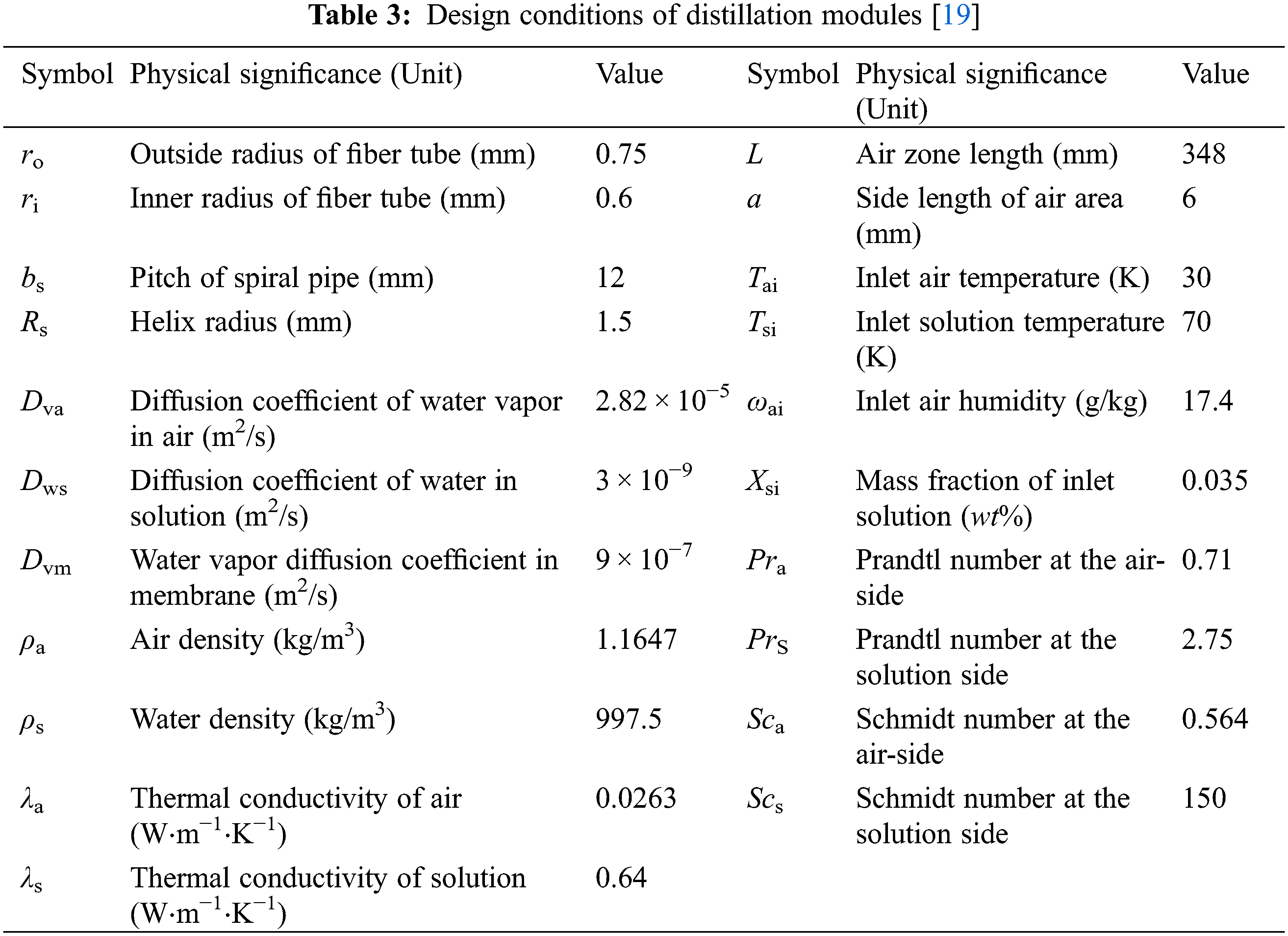
With consideration to practical applications, distillation modules are usually made of hollow fiber membrane tubes. Generally, 2000∼6000 hollow fiber membrane tubes are packed in a module [14]. Since many iteration steps are involved in the numerical solving of the whole module, a typical periodic fiber membrane was chosen as the calculation unit for the simplification of calculation. The physical model in this study was composed of a four-helical HFMTB (Fig. 1). This model lets solution (seawater) flows inside the hollow fiber membrane tube while sweeping air flows outside the fiber membrane tubes. The geometric parameters of helical fiber membrane distillation modules are listed in Table 1.
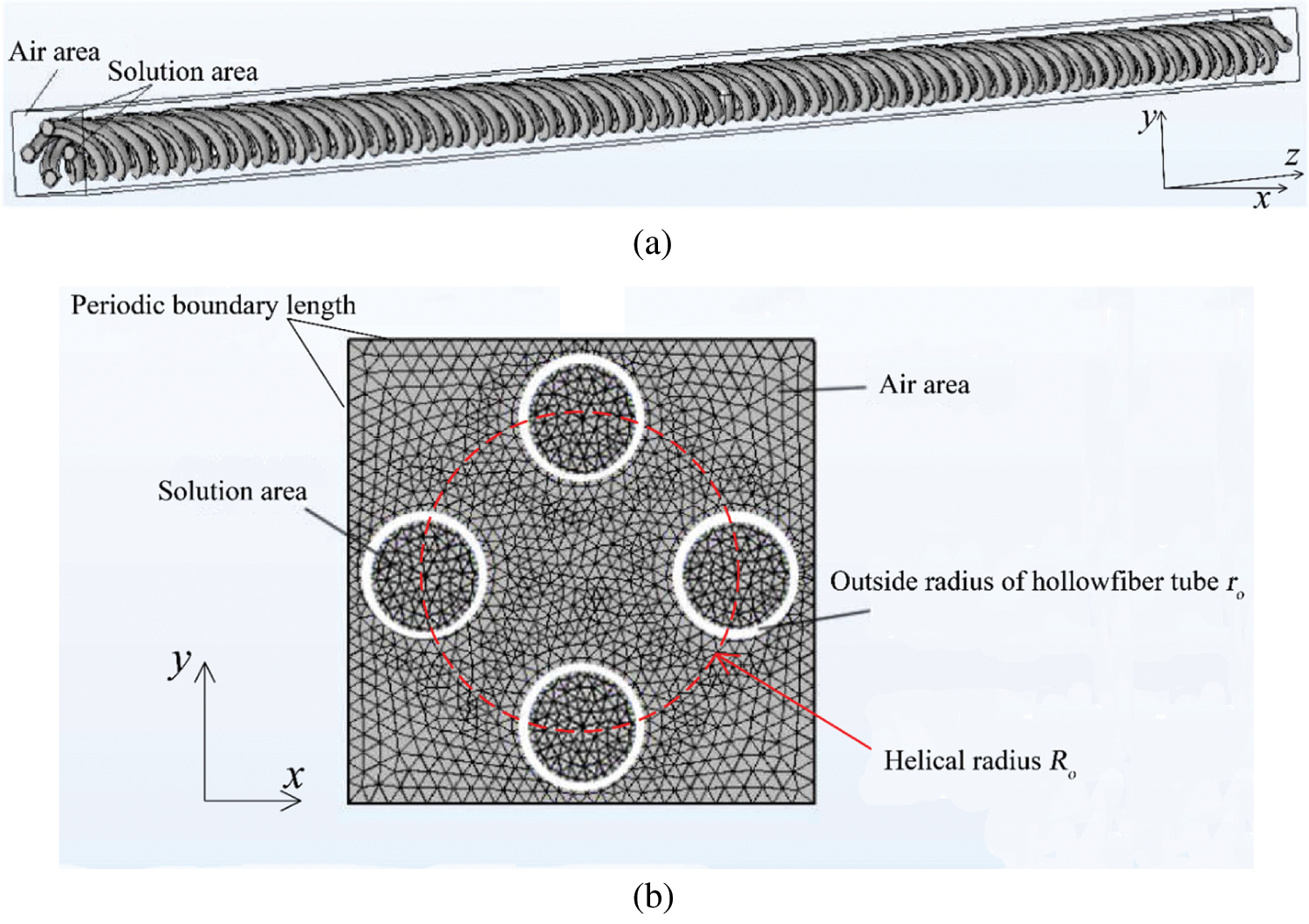
Figure 1: Diagram of four-helical HFMTB (a) and cross-section grid diagram of HFMTB (b)
To simplify the model, some hypotheses were made:
(1) The Reynolds numbers of air and seawater flows are smaller than 2300. Both air and seawater flows are laminar flows.
(2) Air and seawater are hypothesized as incompressible Newtonian fluid that has constant thermophysical properties.
(3) The false air flow and seawater flow are developed fully.
(4) Since Pea = Rea − Pra is higher than 10, axial thermal diffusion and mass diffusion of air and seawater flows can be ignored [9].
(5) Viscosity is introduced into the fluid flow analysis in near-wall region and non-slipping boundary conditions are set.
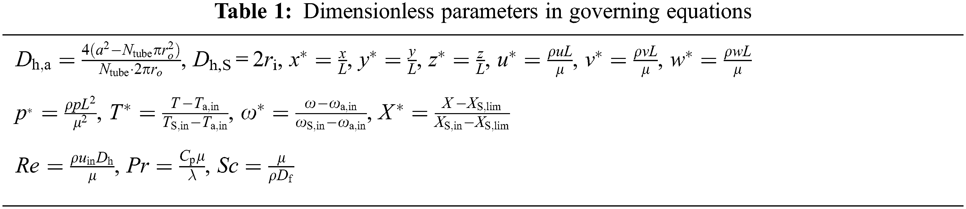
For the air sweeping area, the dimensionless governing equation [19] of fluid flow, heat transfer and mass transfer are gained according to dimensionless parameters in Table 1 [22,23].
Equation of continuity:
where the subscript “a” refers to the air area and the superscript “*” refers to the dimensionless form. x, y and z are coordinate axes in Fig. 1.
Momentum conversation equation:
where p is pressure (Pa).
Energy conservation equation:
where T and Pra are temperature (K) and Prandtl number at the air-side.
Mass conservation equation of water vapor:
where ω and Sca are moisture contents of water vapor (kg/kg) and Schmidt number at the air-side.
In the present study, 3.5 wt% (mass fraction) NaCl was used to replace seawater. The dimensionless governing momentum conservation equation and energy conservation equation at the solution side have the same forms as those at the air-side [19]. The mass conservation equation of water at the solution side is:
where ScS is the Schmidt number at the solution side.
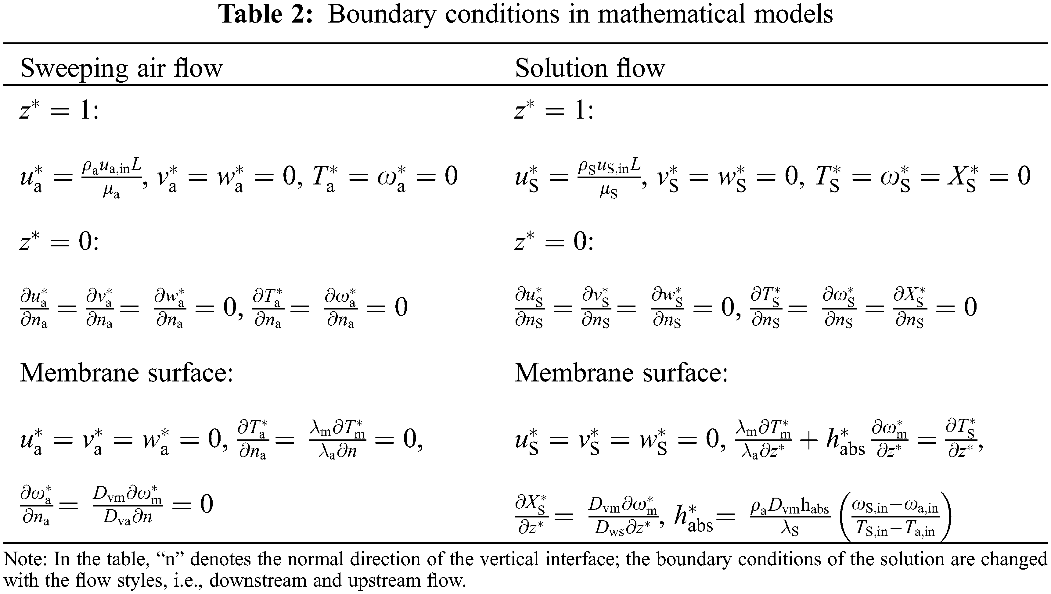
For hollow fiber membrane, the boundary conditions of the surface are conjugate boundary conditions for heat and humidity transfer. The energy conservation equation in the membrane is:
where the subscript “m” refers to the membrane.
The mass conservation equation of water vapor in the membrane is:
It is important to point out that ωa,in refers to humidity of air at the sweeping side (kg/kg) and ωS,in refers to the equilibrium humidity (kg/kg) when the inlet solution is at the temperature (TS,in) and mass fraction (XS,in). Relations among partial pressure of water vapor, temperature and mole fraction of solution can be referred to the Antoine equation [24]:
where pv and TS are partial pressure of water vapor (Pa) and solution temperature (K). The mole fraction of solution can be expressed as:
For wet air, the humidity ratio can be calculated from partial pressure of water vapor [24]:
where Ptot is the barometric pressure (101,325 Pa). In Table 1, XS,in refers to the mass fraction of inlet solution (kg water/kg solution), and XS,lim is the ultimate mass fraction (saturation concentration) which is set 1. At this moment, the solution is salt-free pure water. Ntube refers to the number of hollow fiber tubes. Df is the diffusion rate, including the rate of water diffusion in the air (Dva), the rate of water diffusion in the solution (Dvs), and the rate of water diffusion in the membrane (Dvm). Boundary conditions of the equation can be set as Table 2 based on the above analysis.
To evaluate the heat transfer and mass transfer performances of the distillation modules, calculation formulas of Nusselt number (
3.1 Performances Comparison of Helical and Straight HFMTBs
Under the same design conditions, differences of heat and mass transfer between helical HFMTB and straight HFMTB in downstream flow were analyzed. For the convenience of comparison, the length of membrane modules was set at 0.348 m, which was close to the value given at reference [8].
It can be seen from Table 4 that when the number of hollow fiber tubes is 1, 2, and 4, the mean Nusselt number (
Distributions of velocity, concentration, and temperature at the air-side at cross-section S (z = 0.01 m) of distillation modules with single-straight HFMTB and single-helical HFMRB when ReS = 40 and Rea = 100 are shown in Fig. 2. It is found that air velocities close to the boundary of the module unit are relatively high, while air velocities near the tube are relatively low. This is attributed to the formation of boundary layer near the tube surface in which the air velocity changes from 0 at the surface to the free stream value away from the surface. For a single-straight HFMTB, water vapor concentration and temperature are in symmetric distribution around the tube center. Both water vapor concentration and temperature at the air-side decrease with the increase of distance to each tube center. In the single-helical HFMTB, concentration and temperature of the sweeping air are in asymmetric distribution at cross-section S. However, concentration and temperature are high close to the tube, while they are low at the area far away from the tube.
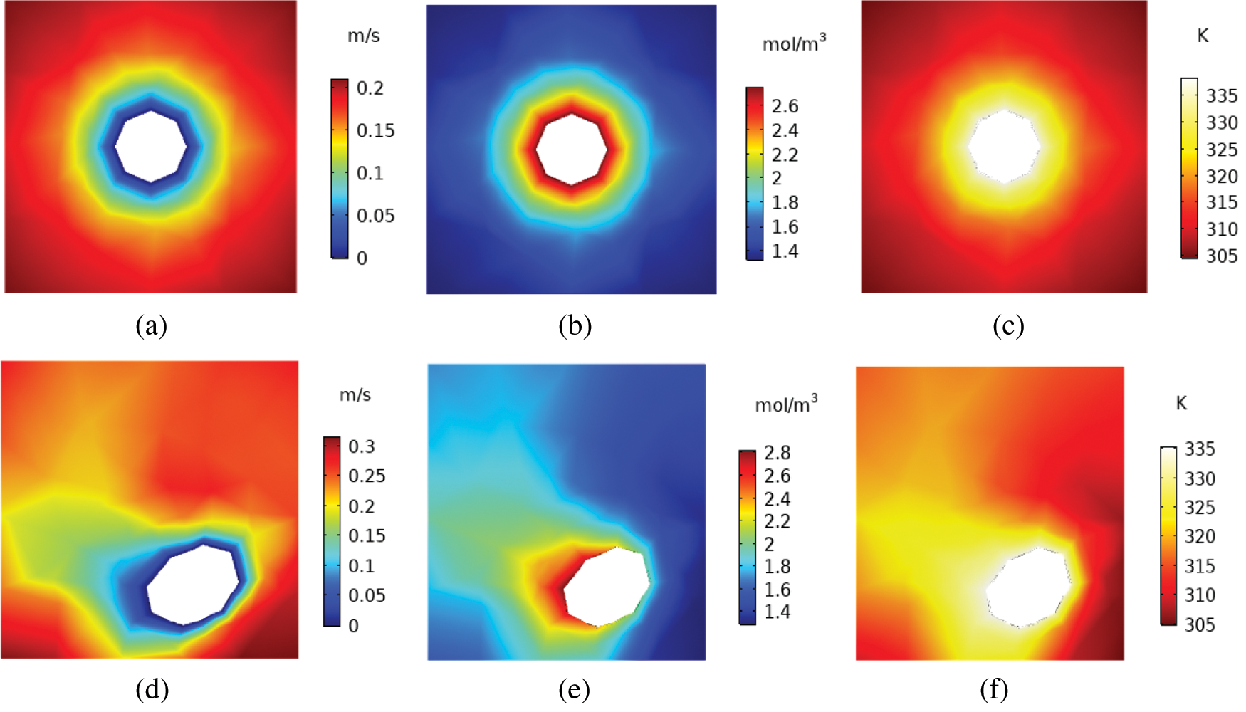
Figure 2: Distribution of velocity, concentration and temperature of distillation module with single-straight tube (a–c) and single-helical tube (d–f) at cross section (z = 0.01 m) with ReS = 40 and Rea = 100 (a) velocity (b) vapor concentration (c) temperature (d) velocity (e) vapor concentration (f) temperature
Distributions of the air-side velocity, concentration, and temperature at cross-section S of distillation HFMTB with double-straight tube and double-helical tube are shown in Fig. 3. Clearly, the air-side velocity profile, vapor concentration, and temperature in straight and helical HFMTBs are symmetric around the connection line of the center of the round tube. High values of concentration and temperature distribute near this axis of symmetry. Concentration and temperature are negatively correlated with the distance to the axis of symmetry. The difference between double-helical tube and double-straight tube lies in the location of high-concentration region. The high-concentration region locates at the area between two helical tubes for helical HFMTB. However, the high-concentration region lies at two sides of double-straight tube for straight HFMTB. This might result from the structure of helical tubes that sweeping air enclosed by helical tubes can only flow along the z direction. With the increase of the number of tubes, high-concentration regions and high-temperature regions are concentrated in the center of HFMTB with four-helical tube (Fig. 4). Yet, for straight HFMTB, the high-concentration region lies at two sides of four-straight tube. The concentration and temperature distributions at the air-side of distillation modules with four-helical tube are symmetric around the center, and the maximum water vapor concentration on a helical tube section is about 3 mol/m3 higher than that on a straight tube section.
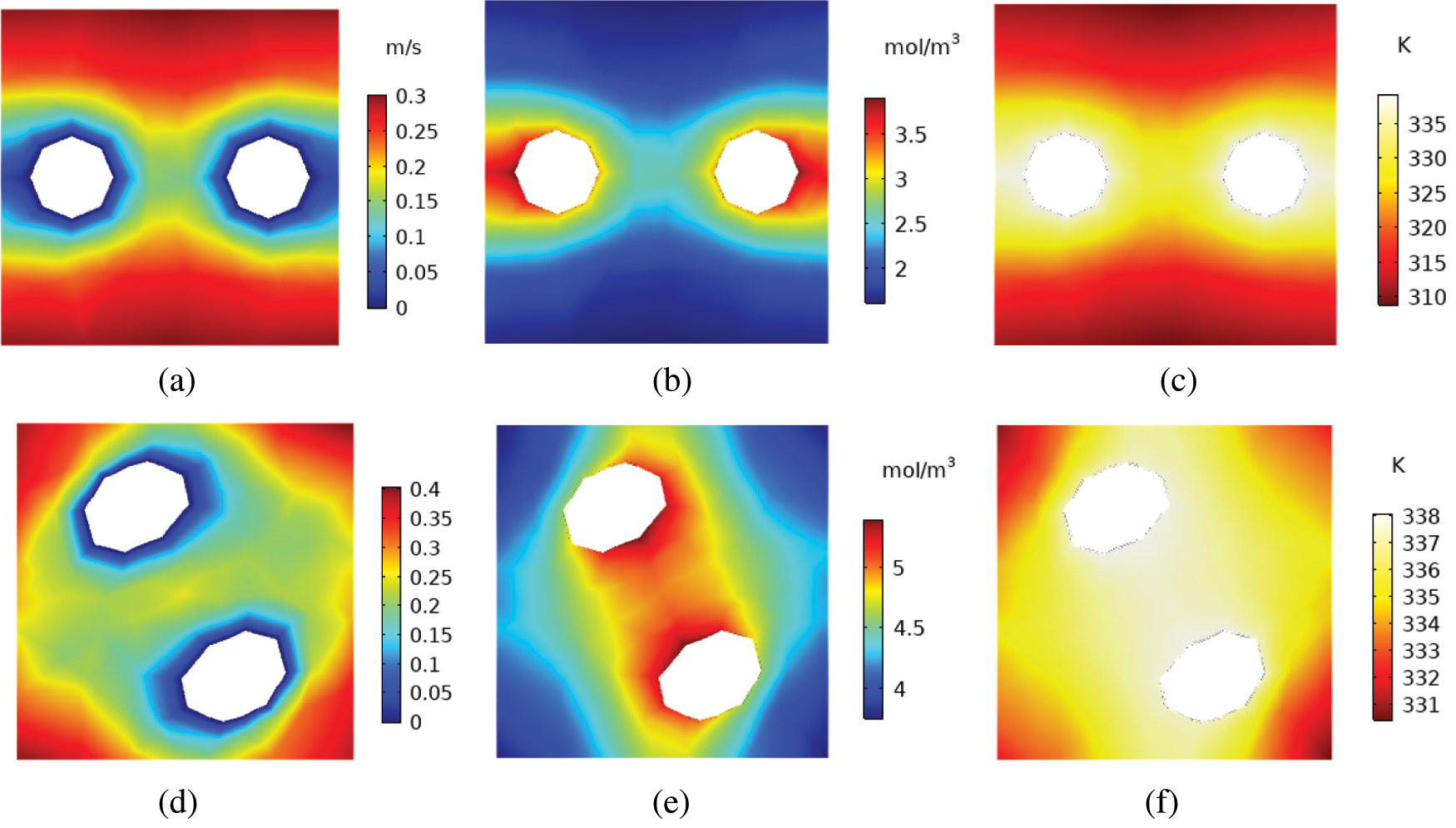
Figure 3: Distribution of velocity, concentration and temperature of distillation module with double-straight tube (a–c) and double-helical tube (e–f) at cross section S (z = 0.01 m) with ReS = 40 and Rea = 100 (a) velocity (b) vapor concentration (c) temperature (d) velocity (e) vapor concentration (f) temperature
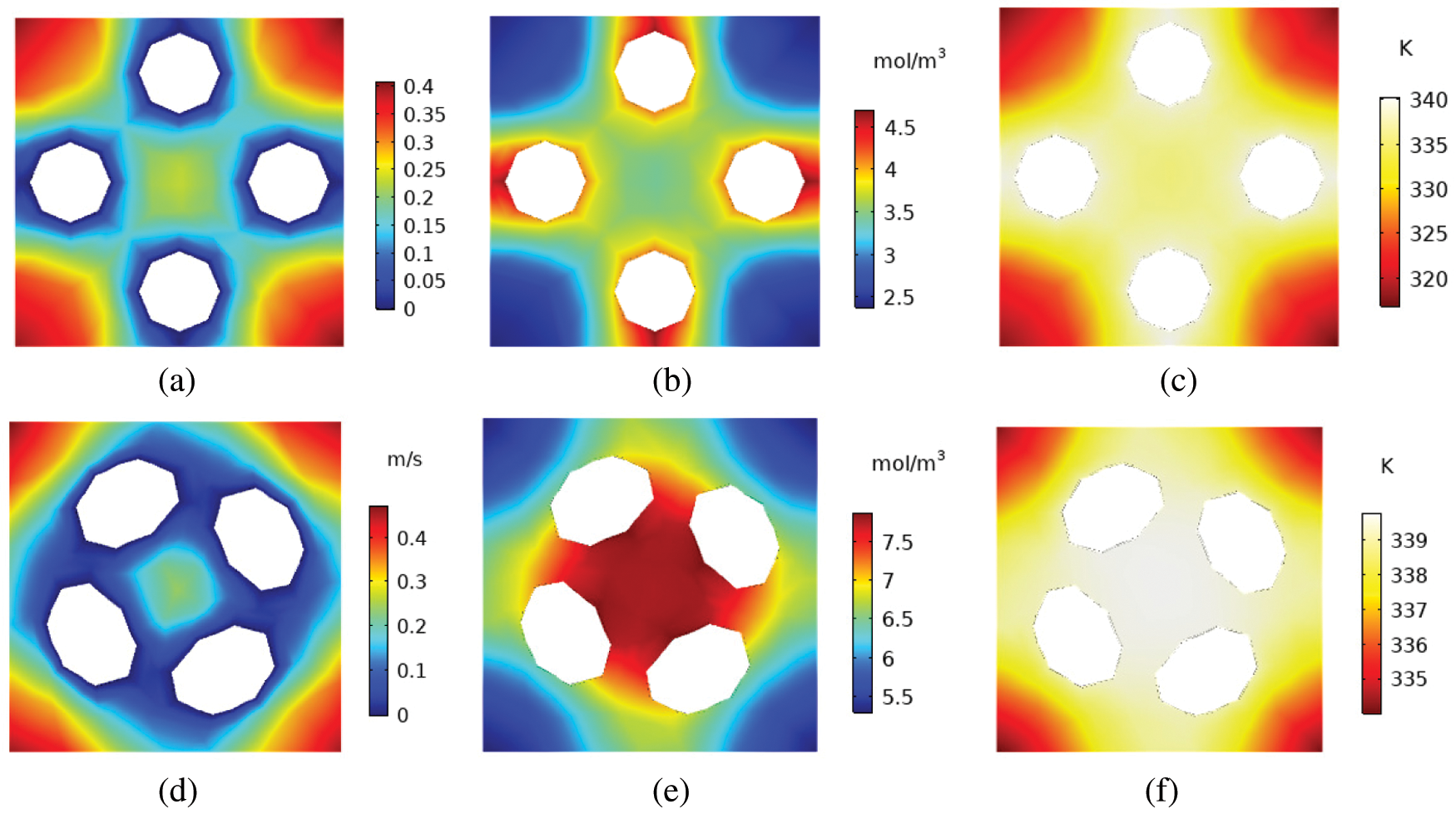
Figure 4: Distribution of velocity, concentration and temperature of distillation module with four-straight tube (a–c) and four-helical tube (e–f) at cross section (z = 0.01 m) with ReS = 40 and Rea = 100 (a) velocity (b) vapor concentration (c) temperature (d) velocity (e) vapor concentration (f) temperature
3.2 Influences of Downstream and Upstream Flow on Performances of Membrane Distillation Modules with Double-Helical Tube
In this section, the performances of membrane distillation modules with double-helical tube under downstream and upstream flow styles were analyzed. The thermophysical properties of the working fluids were consistent with those in Table 3. For the downstream flow style, both the sweeping air and solution flow along the positive direction of the z-axis. It can be seen from Figs. 5a and 5b that the temperature and concentration of water vapor at the air-side reach the peak at the inlet, where strong heat and mass transfer occurs. Under upstream flow, sweeping air and solution flow along the negative direction and positive direction of the z-axis, respectively. In Figs. 5c and 5d, the temperature and concentration of water vapor at the air-side increase gradually along the negative direction of the z-axis and reach the peak at the outlet.
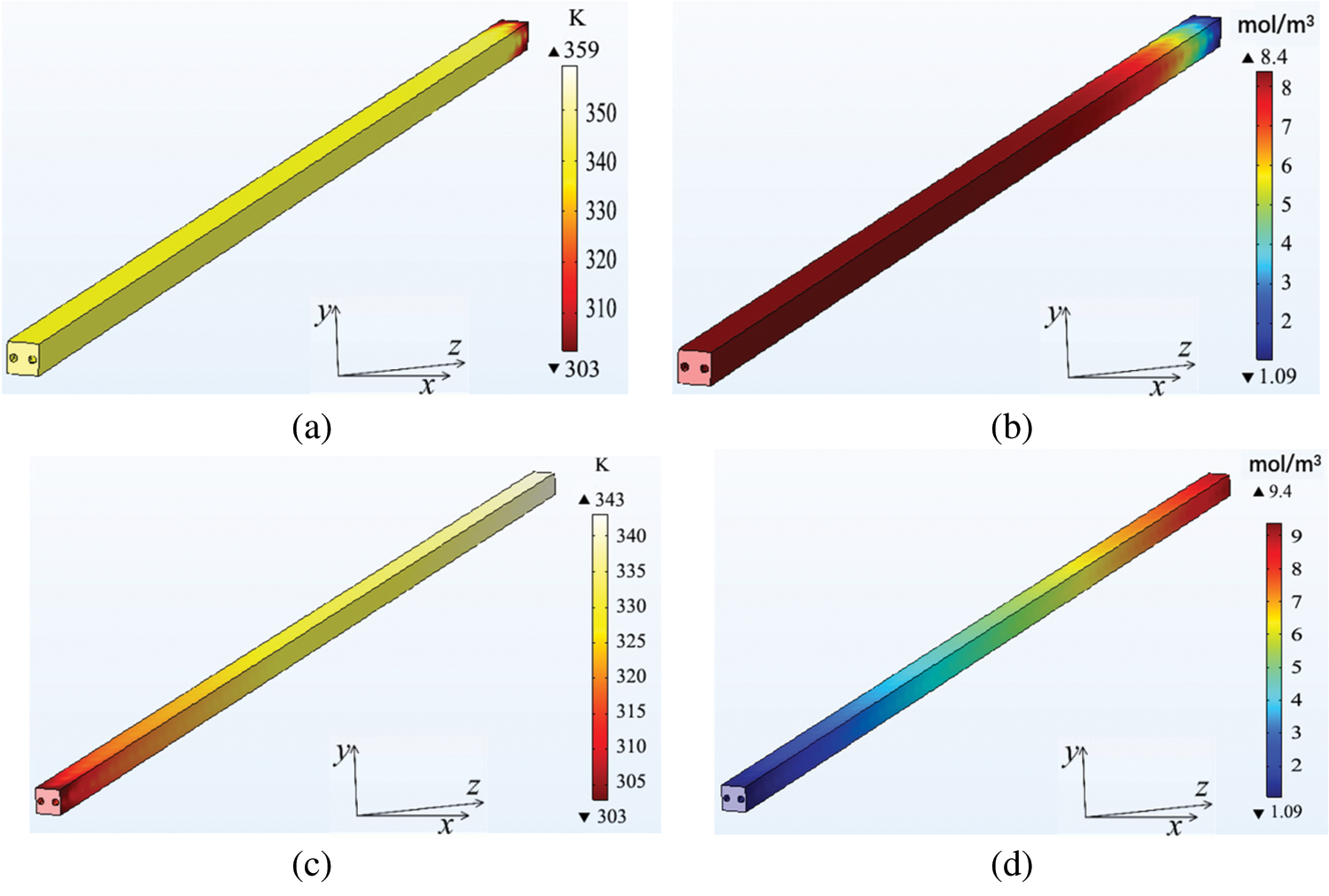
Figure 5: Temperature and concentration distribution of water vapor at the air-side of distillation module with double-helical tube with ReS = 40 and Rea = 100 (a) Temperature distribution of downstream flow (b) Concentration distribution of downstream flow (c) Temperature distribution of upstream flow (d) Concentration distribution of upstream flow
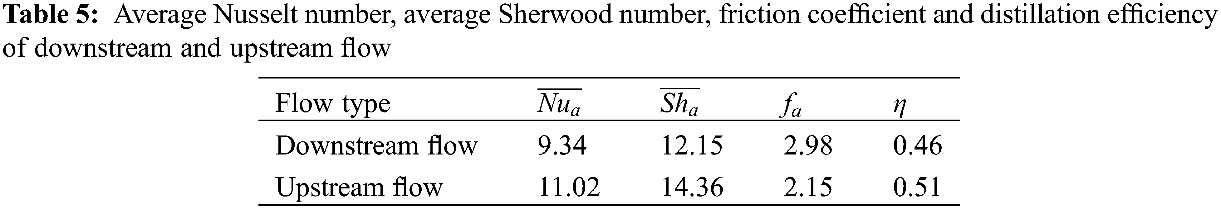
It can be concluded from Table 5 that under the same design conditions,
3.3 Influences of Reynolds Number on Performances of Helical HFMTB
The Reynolds number of air (Rea) and Reynolds number of solution (ReS) were used as variables to analyze their influences on heat and mass transfer performances of distillation modules with double-helical tube under downstream flow. In Fig. 6a,
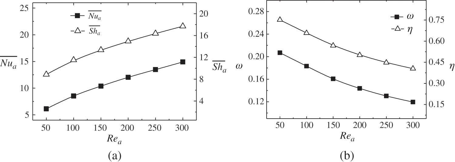
Figure 6: Changes of mean Nusselt number and mean Sherwood number (a), outlet air humidity, and distillation efficiency (b) with Rea number at ReS = 40
The changes of air performances of the distillation module with the double-helical tube under downstream flow when Rea = 100 and ReS ranges within 20∼180 are shown in Fig. 7. It can be seen from Fig. 7a that
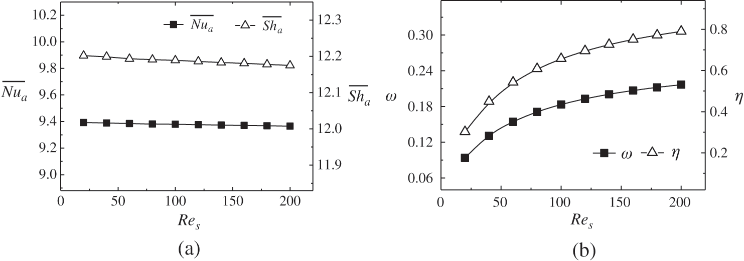
Figure 7: Changes of mean Nusselt number and mean Sherwood number (a), outlet air humidity and distillation efficiency (b) with Res number at Rea = 100
3.4 Influences of Inlet Temperature on Performances of Helical HFMTB
When the inlet air temperature (Ta) increases from 283 K to 323 K, both
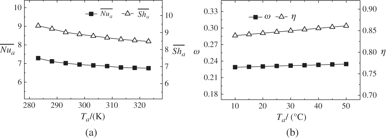
Figure 8: Changes of mean Nusselt number and mean Sherwood number (a), outlet air humidity and air distillation efficiency (b) with inlet air temperature
When TS increases from 323 K to 363 K, both
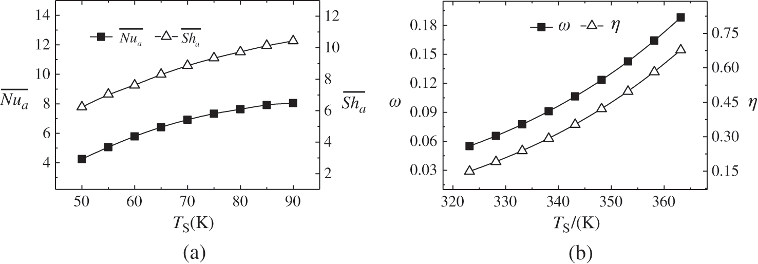
Figure 9: Changes of mean Nusselt number and mean Sherwood number (a), outlet air humidity and air distillation efficiency (b) with inlet solution temperature
This study carries out a numerical simulation analysis on heat and mass transfer and distillation efficiency of a helical HFMTB. The heat and mass transfer performance between the helical and straight HFMTBs was compared under different flow modes, Reynolds number of fluids, and fluid temperatures at the inlet. Some major conclusions could be drawn under the given working conditions: (1) Compared to straight HFMTB, helical HFMTB has higher distillation efficiency and heat-mass transfer performance. (2) Upstream flow-type helical HFMTB is recommended for SGMD due to its higher distillation efficiency and heat-mass transfer performance that can be used as an alternative method in SGMD for sea desalination. (3) Higher Rea values enhance the heat-mass transfer performance of helical HFMTB while causing a significant reduction of the distillation efficiency. On the other hand, with the increase of Res, the distillation efficiency increases, while the heat-mass transfer performance decreases slightly. (4) The increase of Ta results in a slight improvement of distillation efficiency but decreases the heat-mass transfer performance. With respect to the solution side, both the heat-mass transfer performance and distillation efficiency are increased with Ts.
Overall, to acquire higher system performance, it is essential to select the appropriate Reynolds number and inlet temperature of both the air and solution sides. For the module configuration and the range of operating conditions in this study, results obtained suggest that lower Ta, medium Rea, higher Res, and Ts would be an optimum choice; however, further studies are warranted for seawater desalination. Additionally, for a given module where the cross-sectional area is constant, there is a limit to the number of tubes that can pack, depending on the heat exchanger design parameters. Therefore, future studies will be devoted to a comprehensive analysis of the heat exchanger design parameters, such as the tube diameter, tube pitch, tube numbers, and tube layout.
Funding Statement: This work was supported by the Key Special Project for Introduced Talents Team of Southern Marine Science and Engineering Guangdong Laboratory (Guangzhou) (GML2019ZD0108), Science and Technology Planning Project of Guangdong Province, China (2017A050501046), Natural Science Foundation of Guangdong Province (2017A030310185), and Science and Technology Program of Guangzhou, China (202102021199).
Conflicts of Interest: The authors declare that they have no conflicts of interest to report regarding the present study.
1. Zhang, L. Z. (2012). Progress on heat and moisture recovery with membranes: From fundamentals to engineering applications. Energy Conversion and Management, 63, 173–195. DOI 10.1016/j.enconman.2011.11.033. [Google Scholar] [CrossRef]
2. Sphaier, L. A., Worek, W. M. (2004). Analysis of heat and mass transfer in porous sorbents used in rotary regenerators. International Journal of Heat and Mass Transfer, 47(14–16), 3415–3430. DOI 10.1016/j.ijheatmasstransfer.2004.01.016. [Google Scholar] [CrossRef]
3. Singh, D., Sirkar, K. K. (2012). Desalination by air gap membrane distillation using a two hollow-fiber-set membrane module. Journal of Membrane Science, 421–422, 172–179. DOI 10.1016/j.memsci.2012.07.007. [Google Scholar] [CrossRef]
4. El-Bourawi, M. S., Ding, Z., Ma, R., Khayet, M. (2006). A framework for better understanding membrane distillation separation process. Journal of Membrane Science, 285(1–2), 4–29. DOI 10.1016/j.memsci.2006.08.002. [Google Scholar] [CrossRef]
5. Ullah, R., Khraisheh, M., Esteves, R. J., Mcleskey, J. T., Alghouti, M. et al. (2018). Energy efficiency of direct contact membrane distillation. Desalination, 433, 56–67. DOI 10.1016/j.desal.2018.01.025. [Google Scholar] [CrossRef]
6. Zhao, S., Cao, C., Wardhaugh, L., Feron, P. (2015). Membrane evaporation of amine solution for energy saving in post-combustion carbon capture: Performance evaluation. Journal of Membrane Science, 473, 274–282. DOI 10.1016/j.memsci.2014.09.029. [Google Scholar] [CrossRef]
7. Zuo, J., Bonyadi, S., Chung, T. S. (2016). Exploring the potential of commercial polyethylene membranes for desalination by membrane distillation. Journal of Membrane Science, 497, 239–247. DOI 10.1016/j.memsci.2015.09.038. [Google Scholar] [CrossRef]
8. Li, G. P., Zhang, L. Z. (2017). Laminar flow and conjugate heat and mass transfer in a hollow fiber membrane bundle used for seawater desalination. International Journal of Heat and Mass Transfer, 111, 123–137. DOI 10.1016/j.ijheatmasstransfer.2017.03.107. [Google Scholar] [CrossRef]
9. He, Q., Tu, T., Yan, S., Yang, X., Duke, M. et al. (2018). Relating water vapor transfer to ammonia recovery from biogas slurry by vacuum membrane distillation. Separation & Purification Technology, 191(31), 182–191. DOI 10.1016/j.seppur.2017.09.030. [Google Scholar] [CrossRef]
10. Janajreh, I., Kadi, K. E., Hashaikeh, R., Ahmed, R. (2017). Numerical investigation of air gap membrane distillation (AGMDSeeking optimal performance. Desalination, 424, 122–130. DOI 10.1016/j.desal.2017.10.001. [Google Scholar] [CrossRef]
11. Lawal, D. U. Khalifa, A. E. (2016). Experimental investigation of an air gap membrane distillation unit with double-sided cooling channel. Desalination and Water Treatment, 57(24), 11066–11080. DOI 10.1080/19443994.2015.1042065. [Google Scholar] [CrossRef]
12. Alsalhy, Q. F., Ibrahim, S. S., Hashim, F. A. (2018). Experimental and theoretical investigation of air gap membrane distillation process for water desalination. Chemical Engineering Research and Design, 130, 95–108. DOI 10.1016/j.cherd.2017.12.013. [Google Scholar] [CrossRef]
13. Al-Anezi, A. H., Sharif, A. O., Sanduk, M. I., Khan, A. R. (2012). Experimental investigation of heat and mass transfer in tubular membrane distillation module for desalination. ISRN Chemical Engineering, 2012, 8. DOI 10.5402/2012/738731. [Google Scholar] [CrossRef]
14. Li, G. P., Zhang, L. Z. (2018). Three-dimensional turbulent flow and conjugate heat and mass transfer in a cross-flow hollow fiber membrane bundle for seawater desalination. International Journal of Heat and Mass Transfer, 120, 328–341. DOI 10.1016/j.ijheatmasstransfer.2017.12.044. [Google Scholar] [CrossRef]
15. Karanikola, V., Corral, A. F., Jiang, H., Sáez, A. E., Ela, W. P. et al. (2015). Sweeping gas membrane distillation: Numerical simulation of mass and heat transfer in a hollow fiber membrane module. Journal of Membrane Science, 483, 15–24. DOI 10.1016/j.memsci.2015.02.010. [Google Scholar] [CrossRef]
16. Charfi, K., Khayet, M., Safi, M. J. (2010). Numerical simulation and experimental studies on heat and mass transfer using sweeping gas membrane distillation. Desalination, 259(1–3), 84–96. DOI 10.1016/j.desal.2010.04.028. [Google Scholar] [CrossRef]
17. Huang, S. M., Yang, M., Tu, J., Shao, Y., Zuo, Y. (2017). Sweeping air membrane distillation: Conjugate heat and mass transfer in a hollow fiber membrane tube bank with an in-line arrangement. International Journal of Heat and Mass Transfer, 108, 2191–2197. DOI 10.1016/j.ijheatmasstransfer.2017.01.088. [Google Scholar] [CrossRef]
18. Zhang, L. Z. (2011). Heat and mass transfer in a randomly packed hollow fiber membrane module: A fractal model approach. International Journal of Heat and Mass Transfer, 54(13–14), 2921–2931. DOI 10.1016/j.ijheatmasstransfer.2011.03.005. [Google Scholar] [CrossRef]
19. Huang, S. M., Chen, Y. H., Yuan, W. Z., Zhao, S., Hong, Y. et al. (2019). Heat and mass transfer in a hollow fiber membrane contactor for sweeping gas membrane distillation. Separation and Purification Technology, 220, 334–344. DOI 10.1016/j.seppur.2019.03.046. [Google Scholar] [CrossRef]
20. Vilemas, J. V., Poškas, P. J. (1993). Heat transfer and flow in spiral channels and coils. Journal of Engineering Physics and Thermophysics, 64(6), 537–545. DOI 10.1007/BF01089953. [Google Scholar] [CrossRef]
21. Chang, S. W., Chiang, K. F., Kao, J. K. (2011). Heat transfer and pressure drop in a square spiral channel roughened by in-line skew ribs. International Journal of Heat and Mass Transfer, 54(15–16), 3167–3178. DOI 10.1016/j.ijheatmasstransfer.2011.04.013. [Google Scholar] [CrossRef]
22. Incropera, F. P., Dewitt, D. P. (1996). Introduction to heat transfer, 3rd edUSA: Johns Wiley & Son. [Google Scholar]
23. Kays, W. M. (1966). Convective heat and mass transfer. USA: McGraw-Hill. [Google Scholar]
24. Khayet, M., Godino, M. P., Mengual, J. I. (2002). Thermal boundary layers in sweeping gas membrane distillation processes. American Institute of Chemical Engineers Journal, 48(7), 1488–1497. DOI 10.1002/(ISSN)1547-5905. [Google Scholar] [CrossRef]
 | This work is licensed under a Creative Commons Attribution 4.0 International License, which permits unrestricted use, distribution, and reproduction in any medium, provided the original work is properly cited. |