| Journal of Renewable Materials |
DOI: 10.32604/jrm.2022.017573
ARTICLE
Tensile and Stress Analysis of Hybrid Composite Prosthetic Socket Reinforced with Natural Fibers
Materials Engineering Department, University of Technology, Baghdad, Iraq
*Corresponding Author: Noor K. Faheed. Email: n.kadhim12@gmail.com
Received: 20 May 2021; Accepted: 26 July 2021
Abstract: Natural fibers and their composites are the evolving movements in material science, and with that, the utmost use of plant-based fibers has become the focus of this research. Sisal and cotton natural fibers were used to construct a prosthetic socket as an attempt to substitute material currently available in the manufacturing of sockets. The vacuum bagging technique was adopted to produce a below-knee socket. The influence of different fiber layering sequences on the volumetric and mechanical characteristics was estimated experimentally and numerically. Mechanical tensile tests were used to assess laminated specimens, such as tensile strength, young modulus, and elongation percentage. The number and type of reinforcing layers had an effect on mechanical properties, and the best composite specimens were three layers of sisal with two layers of carbon fiber, with tensile strength and modulus of elasticity reaching (261–4760) MPa, respectively. The finite element method (ANSYS-16.1) was used to anatomize by seeing the contours distribution of safety factor, equivalent Von Mises stress, equivalent Von Mises strain, and total deformation. This procedure was executed by building ten models for the socket, which served as three-dimensional structural composite materials. The results of the present study advocate that the arrangement of natural and synthetic reinforcements allow the preparation of bio-composites with enhanced performance. This work revealed the assets of sisal and cotton fiber hybrid reinforced PMMA resin composites (hybridized at diverse volume percentages and lamination layup), which have not been tried up to now.
Keywords: Natural fiber; tensile; cotton; sisal; prosthetic; socket; carbon; glass fibers
To renovate the form and the lost roles of people with limb amputation, artificial limbs, also known as prostheses, are often used [1]. Artificial prosthetic constituents include several portions forming the socket, pylon, and foot. The trans-tibial prosthetic socket is considered critical because the lower limb (stump) lacks weight-bearing abilities comparable to the foot [2,3]. To achieve effective fitting procedures for prosthetic sockets, an understanding of the biomechanical construction of these sockets and the suitable materials that make up their mass and thickness is necessary to achieve the necessary load diffusion in the lax tissues and bone of the remaining limb [4].
War, land mines, and the main usual tragedies, for instance, earthquakes and deluges, in addition to chronic illnesses, including vascular infections, for example, diabetic difficulties, arteriosclerosis, and thrombosis are altogether donating aspects to the universal request for prostheses [5,6]. The need to use alternative and accessible materials should be considered when costly materials are not available and high demand for prostheses, in earthquakes or combat and battle districts, biomaterials derived from plants may offer the needed substitute [7]. Recently, developments in the progress of composite materials have qualified main enhancements in the design of contemporary orthopedics and prosthetic expedients. Composites are defined as an engineered materials prepared from two or more elements, each of which contributes diverse physical properties that can be joined [8,9]. At present, fiber-reinforced polymer composites are considered as one of the most widely used multi-phase resources in orthopedics. Similarly, the majority of upper- and lower-limb prostheses are made of polymer matrix composites [10,11]. Among conventional fiber reinforcements used in orthopedics, fiberglass is considered the most common and cost-effective composite reinforcement. While being one of the heaviest types of reinforcements, it is easy to soak with resin and achieve in many ways and qualities. Fiberglass offers durability and flexibility, due to the fibers being twice as strong under compression as in tension. However, for orthopedic appliances, carbon fiber is considered the most valued form of reinforcements since it supplies stiffness and the ability to hold its shape under the influence of stress due to its remarkable strength under both tension and compression [4].
In recent years, there have been countless developments in the design and usage of materials in socket production. Typical sockets are made by entrenching various films of perlon stockinet fibers, woven carbon fabric, and a PMMA polymer resin. These conventional materials originate from non-sustainable bases, along with generating irritant radiation from harmful gases and dust. Consequently, it needed costly professional health and safety equipment. The socket is made from resin and natural fibers intended to improve mechanical strength and durability [7]. Research about the use of natural fibers is very vital to accomplish because their availability is plentiful and they can be reprocessed. Natural fibers can potentially be proven to produce substitute products like prosthesis sockets [12].
The researchers who studied this field (Oleiwi et al.) [13] explored the tensile and buckling behavior of natural fiber-reinforced composites by altering the number of Jute fiber layers and their angles (45° & 0°/90°). The finite element method (Ansys APDL-15) was used to analyze: total deformation, von-Mises equivalent stress, von-Mises elastic strain with buckling investigation, Critical Buckling stress, and Buckling Figure Mode of Composite. The consequences showed that tensile strength and modulus of elasticity were enhanced with increasing the number of Jute reinforcing layers in the direction (0°/90°) of fibers under tensile load. Juma et al. [14] suggested lamination (1 bamboo 2 fiber carbon 1 bamboo) and debated it with the presently obtainable lamination (4 Perlon 2 fiber carbon 4 perlon) to obtain physical qualifications, mechanical and fatigue features for the manufacture of above the knee prosthetic socket. Muhammad et al. [15] studied the tensile and fatigue features of the above-knee prosthetic socket prepared from (PMMA) as a matrix and (perlon, cotton, glass, and monofilament) as reinforcement. Finite element analysis (FEA) was used to assess the composite general behavior. Material test and FEM (Ansys 14.5) results show that the natural fiber-reinforced composite has improved tensile and fatigue features than the conservative glass fiber-reinforced composite. Irwan et al. [16] produced a socket prosthesis from natural fibers, ramie natural fiber reinforced epoxy (RE) composite to construct a socket with fiberglass polyester composites (FGP). The production process was continued by using the filament winding technique. Tensile and flexural tests were executed on sample laminations. The results showed that socket prostheses prepared from RE have the best tensile and flexural strengths when compared to FGP composite materials. Sukania et al. [17] aimed to investigate the tensile strength of Banana Fiber Reinforced Epoxy Composite Materials (BFRECM). The compressed and vacuum process engineering process was used to produce samples with a fiber volume fraction of 10%, 20%, 30%, 40%, and 50%. Resan et al. [18] reconnoitered the production of a novel kind of socket by an innovative technique (modular socket method) that used straight lamination on the remaining limb of the patient experimentally. Socket materials were exposed to tensile and creep (500) tests to regulate their mechanical features. In addition, a numerical technique was used to obtain the safety factor employing AutoCAD software and ANSYS 15. The results were compared to the results of the traditional method (vacuum molding technique) to determine the best and most contented process for socket contrivance. Al-Khazraji et al. [19] reported the influence of materials nature on the tensile assets (Young’s modulus, tensile strength, and elongation at break) and fatigue features (S-N curve and fatigue limit) of the trans-tibial prosthetic socket, by counting socket’s strength (Experimentally, Numerically, and Academically) of five diverse reinforcement [perlon, carbon, glass, (carbon+glass) fibers and (carbon+glass) fibers+SiO2 particles] with Epoxy polymer matrix. The fallouts displayed that the strengthening with perlon offered the lowest in all dignified assets, while (Epoxy+Carbon corroboration) contributed best investigational, numerical, and theoretic outcomes which mark them the finest applicant to advance the fatigue features of the trans-tibial prosthetic socket.
The outcomes of our experiments where we surveyed the probability of creating a lower prosthetic limb socket made from renewable resources were presented. This paper considers hybrid fiber-reinforced polymer matrix composites (a mix of natural and synthetic fibers). The hybrid fiber reinforcements in the composites can endure greater loads associated with single-fiber reinforcements in a diverse path proven on the reinforcement, and the contiguous matrix keeps them in the preferred position and orientation, performing as a greater load transfer medium between them.
The focus was to first recognize suitable resin polymer and natural fiber arrangements by conducting a series of tests. The test sockets that were prepared to use stockinet woven were from the best fiber. The goal is to prove that prosthetic limb sockets can be built from renewable, safe resources without conceding the strength of these composite materials.
This section describes the materials, equipment, and preparation stages of socket manufacturing which could supply helpful mechanical features. Also, describe the details of the mechanical and morphological tests.
Materials used in the below-knee lamination socket for this research are sisal and cotton fibers, which were made by (Changzhou Doris Textile Co., Ltd., China) as a woven mat. They were dipped in a 5% NaOH solution for about two hours at room temperature. After the alkaline treatment, sisal and cotton fibers were thoroughly washed by running water so the fiber is stronger and more durable and achieves better bonding with matrix materials.
The additional materials needed are unidirectional carbon fabric (a type of carbon reinforcement that is non-woven and features all fibers running in a single, parallel direction, manufactured by Otto Bock Company, China), glass fiber (manufactured by Otto Bock Company, China), Perlon stockinet (item name from the company is (623T5), manufactured by Otto Bock Company, China), lamination resin: Polymethyl methacrylate (PMMA), hardening powder (Otto Bock Health Care 617P37), polyvinyl.
2.2 Equipment Used in This Study
1. A positive Jepson mold with a rectangular figure and a size of 25 × 20 × 10 cm3.
2. The vacuum forming system includes a vacuum pump and diverse kinds of stands, pipes, and tubes.
3. A digital vernier and a sensitive weighing device for measuring the dimension and weight of samples.
4. The mechanical workshop was done in the university’s technical training and the workshop center includes different gears for cutting by CNC machine.
2.3 Fabrication of Laminate Composites
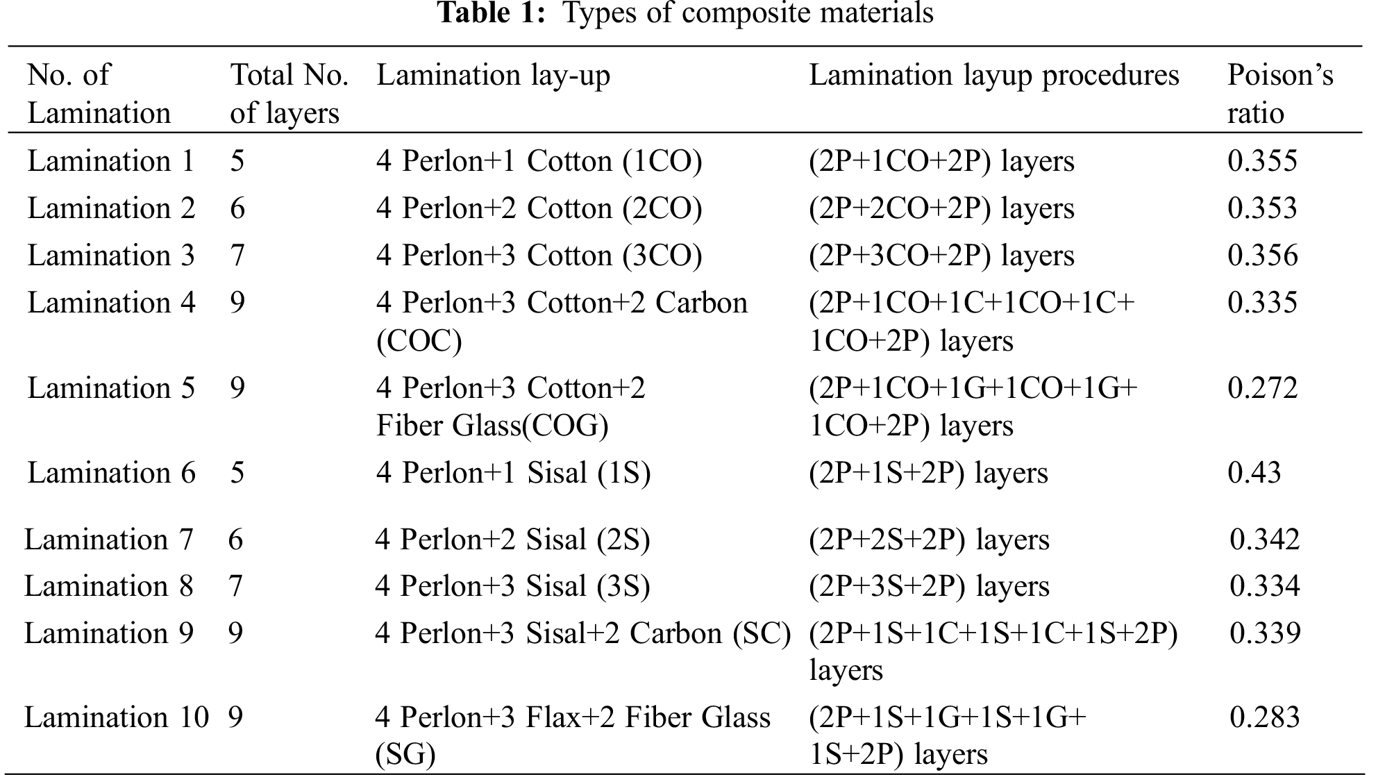
The masses of reinforcement and matrix material are calculated based on the obligatory volume fractions. Specimens were prepared by the vacuum modeling procedure as shown in Fig. 1 and per the lamination layup given in Table 1. For fabricating the specimens, the gypsum mold is set and fixed at the entrance of the pressure vacuum and associated with the pipes of the pressure system. The PVA layer was positioned on the positive mold, then pressure valves were released to a value of 4 KPa at room temperature, as shown in Fig. 2a. Reinforcement layers were applied (2 layers of perlon fiber), then one layer of cotton fiber, and another two layers of perlon fiber as shown in Fig. 2b. A layer of PVA bag is placed above the composite material layers, and then the string is used to tie up the end of the PVA bag. The matrix materials which hold a mix of PMMA polymer resin and hardening powder combined conferring to the known standard ratio in which every 100 parts of acrylic resin are commingled with (2–3) parts of powder and then inserted into the layers and evenly given through the small tube as shown in Fig. 2c and after continuing for 10 min, a cubic composite material is acquired as shown in Fig. 2d. After cooling, the composite materials are cut off to obtain manufacturing samples to allow testing. This procedure was repeated for all the laminations. The steps of the vacuum molding technique are shown in Fig. 2.

Figure 1: Scheme of the vacuum fabrication process

Figure 2: The steps of test specimens preparation
The tensile investigation was employed to reach a stress-strain curve aimed at each laminated composite sample. This curve is applied to obtain tensile characteristics of these specimens, such as tensile strength (UTS), elastic modulus (E), and elongation percentage at the break. The tensile test is performed following the (ASTM D638-03 type IV standard) [20]. Using a tensile device (universal testing machine), kind (Instron) at a crosshead speed (strain rate) of 5 mm/min, and the load was applied until the specimen broke. Fig. 3 illustrates the standard tensile test sample and the tensile test instrument that was used in this test.

Figure 3: (a) Sample of the specimens before the test, (b) The tensile test machine
The broad analysis by utilizing ANSYS has three discrete stages; the first step is constructing the geometry as a model and the second step stratifying the boundary conditions load and reaching the solution, then the third step reviewing the results [21–23]. For analyzing the motion system of patients, the design of the socket was alienated into four basic classes (anterior, posterior, lateral, and medial) according to their weight-bearing properties. Then interface pressures amid the residual limb and the socket were noted as each patient walked at a self-selected speed [24]. To evaluate von-Mises Stress and deformation, the boundary condition was set to the model of the socket. The boundary condition forms apply the measured interface pressure values at different regions of the socket and provide fixed support at the lower surface, specifically at the bottom tip of the socket. The mechanical properties of each group of composite material parameters are added to the ANSYS data to conclude the final overall results of this model.
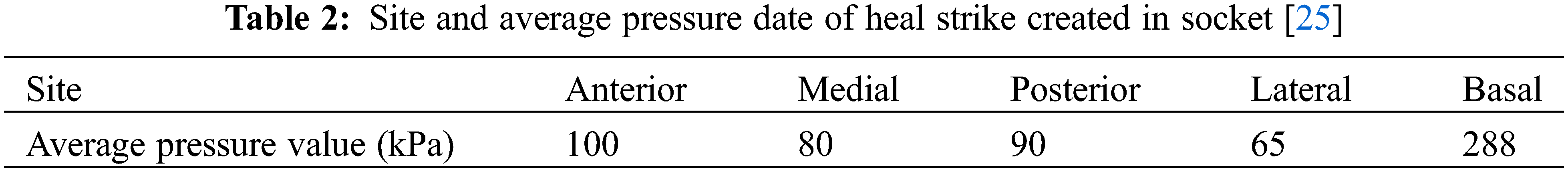
In this work, with the aid of ANSYS Workbench 16.1 software, finite element analysis (FEM) was used as a numerical tool to imitate a prosthetic socket of 75.5 kg in body mass. The socket is examined at the riskiest load situations, which occur at heel strike during the gait cycle. Pressures in Table 2 were stratified on the plane of the socket.
The meshing process has been completed by selecting the volume then the profile of the element was appointed as a tetrahedron (Automatic meshing) as shown in Fig. 4. Discouraging the interface pressure gives precise positions. This meshing includes a complete number of elements (8935) with an overall number of nodes of (18138) conferring involuntary ANSYS features and node counters.

Figure 4: The meshed socket
5.1 Physical Characteristics of Samples
Figs. 5 and 6 show the effect of reinforcing material used in the composite prosthetic socket on the average thickness and density of the composite specimens. There were no significant differences across all the reinforcements. The Matrix material seemed to bond better to specific materials than others, based on thickness comparison. In addition, the absorbing ability in the lamination is increased slightly when cotton fibers are used, leading to increased density, thickness, and hybrid (Cotton Glass) reinforcement having the highest density and thickness [15].

Figure 5: Effect of reinforcing material on the average thickness of the composite specimens

Figure 6: Effect of reinforcing material on the average density of the composite specimens
Fig. 7 illustrates the variation of the volume fraction of composite specimens with changing the type of reinforcing material. It can be seen from this figure that the specimens with hybrid (Cotton Glass) reinforcement have the highest volume fraction [25].

Figure 7: Variation of volume fraction of composite specimens with changing the type of reinforcing material
Fig. 8 proves the influence of reinforcing material and matrix on the strength/density ratio. It is obvious from the figure that the strength/density ratio of hybrid (Sisal, Perlon, and Carbon) reinforcement composite is superior to other laminations with 215.16 MPa.cm3/g [26], while Lamination 1 takes the lowest (strength/density) ratio in contrast with the other nine groups with 32.88 MPa.cm3/g.
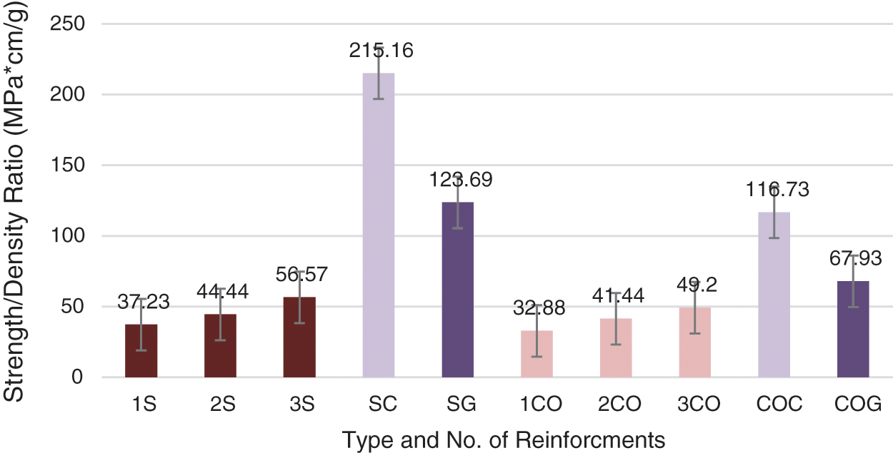
Figure 8: Effect of reinforcing material and matrix on the strength/density ratio
This investigation relates the tensile characteristics (Young’s modulus, Ultimate tensile strength, and percentage of elongation at break) of trans-tibial composite prosthetic sockets. Altering the nature of reinforcement has an excessive impact on tensile properties.
Figs. 9, 10, the values of UTS rise by growing the number of sisal and cotton layers. As the addition of fiber layers increases, the tensile strength will be improved. For these specimens, the difference in strength is due to the difference in the properties of sisal, cotton, glass, and carbon fibers. Therefore, by comparing the tenth laminations, the three layers of sisal fiber with carbon fiber consume the uppermost values of UTS. This can be attributed to the presence of carbon fibers, thus confirming the transmission of loads from matrix to fiber [26,27]. According to Figs. 9, 10, cotton fiber did not improve the matrix material’s properties in any way, and the matrix’s tensile properties prevailed in the overall performance of the composites [15]. It was also noted that the tensile strength amplified with increasing volume fraction [28].
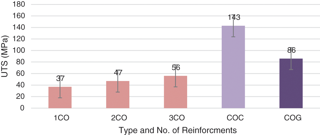
Figure 9: Tensile strength and number of cotton fiber layers
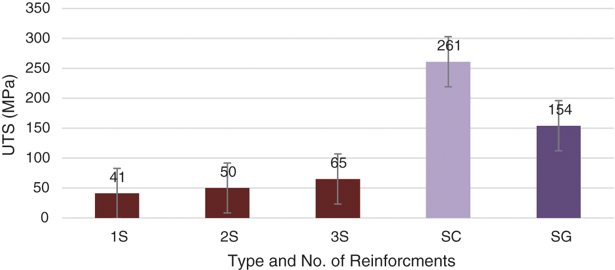
Figure 10: Tensile strength and number of sisal fiber layers
Young’s modulus is a measure of the stiffness of a part. Figs. 11 and 12 show the association between the modulus of elasticity and types and the number of fiber layers (sisal, cotton, glass, and carbon) that were added to the (PMMA) matrix. From these figures, the modulus of elasticity rises with an increasing number of reinforcing layers [29]. The modulus of elasticity increased slowly when carbon fiber was added to three layers of cotton and sisal fiber. This can be attributed to rising binding forces with escalated layers of carbon fibers. Therefore, by comparing the tenth laminations, the three layers of sisal fiber with carbon fiber consumed the maximum values of modulus of elasticity for composites. This is owed to the existence of carbon fibers, which guarantee the spread of loads from matrix to fiber and increase the strength and stiffness of carbon fibers [26]. While Lamination 1 with hybrid (perlon&carbon) reinforcements has the lowest modulus of elasticity, with 1.67 GPa.

Figure 11: Modulus of elasticity and number of sisal fiber layers

Figure 12: Modulus of elasticity and number of cotton fiber layers
The percentage of elongation-at-break value was estimated to see the effect of fiber content on the ductility of the composite specimens. The increase in the number of sisal and cotton reinforcing layers led to a reduction in the elongation percentage values for samples [30]. In addition, it is noted that the elongation of natural fiber-reinforced composites is lower as compared with the hybrid (natural and synthetic) reinforced composite materials, which shows that the addition of these reinforcements to PMMA did not increase its elasticity. It can be seen from this Figs. 13 and 14 that the specimens with hybrid (Cotton Glass) reinforcement have the highest percentage of elongation at break. This is as the reinforcements are stiffer compared with the matrix and so they execute a mechanical restriction on the laminated composite specimens.

Figure 13: Elongation percentage and number of cotton layers
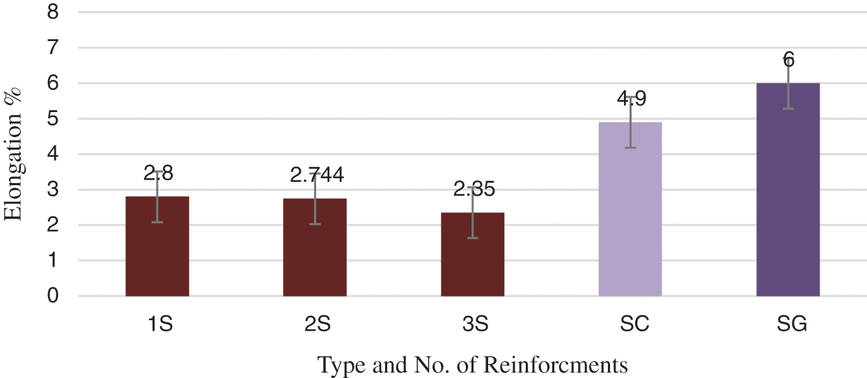
Figure 14: Elongation percentage and number of sisal layers
5.3.1 Equivalent Stress (von-Mises Stress)
Numerical analysis is executed to find the values of stresses produced in the parts of the socket due to the generation of the interface pressure between the socket and the muscles and body weight during walking. The equivalent von-Mises Stresses analysis gave us knowledge of the amounts of stress and spread in the socket and the deformation generated by the interface pressure in the socket. The results displayed that the highest value of stress produced in the socket was presented with Lamination 6 (2 Perlon+1 Sisal+2 Perlon) layers (equivalent to (26.83 MPa)) and placed at the center of the anterior side in the tibia bone while the sides (posterior, medial, and lateral) partake pressure that is less than the anterior side Fig. 15 presented the results obtained by comparing the values of equivalent von-Mises stress obtained for all the composite samples, while Fig. 16 showed the outline designs of the composites which spectacle the general distribution of the Von Mises stresses through the material, in addition to governing the estimated position and value of the extreme Von Mises stresses.

Figure 15: Equivalent von-Mises Stress distribution of composite

Figure 16: Analysis of von-Mises Stress of the socket
5.3.2 Von Mises Analysis Strain
From Fig. 17, it can be perceived that the uppermost value of strain produced in the socket is equivalent to (0.016) placed at the center of the anterior side of the tibia bone, but the sides (posterior, medial, and lateral) partake pressure that is less than the anterior side with Lamination 1 (2 Perlon+1 Cotton+1 Carbon+1 Sisal+1 Carbon) and this can be attributed to the diverse mechanical properties of cotton, sisal, and carbon fibers [26], Fig. 18 displays the outline design of the equivalent elastic strain of all the lamination composites that were tested in this study.

Figure 17: Equivalent von-Mises strain of composite

Figure 18: Analysis of von-Mises strain of the socket
5.3.3 Safety Factor on Socket Materials
These are counterplots concerning mechanical failure at a specified design life. In Ansys, the highest value of safety factor shown is 15, but when the stress in a precise location develops greater than the strength of the material, the safety factor ratio develops inferior to 1, and with this, there is a risk which is mainly that in an exact part of the model, the stress is greater than the strength the material can stand and failure is projected earlier in the design life [31]. Fig. 19 showed minimum numerical safety factors for all composite samples where the combination of sisal fibers and carbon fiber showed the highest results and that can be contributed to the impressive properties of carbon fiber while Lamination 1 takes the lowest safety factor in contrast with the other nine groups with (1.21) which can be contributed to the properties of cotton and perlon reinforcement fibers. Fig. 20 depicts the dispersion of the composites’ safe and unsafe areas.
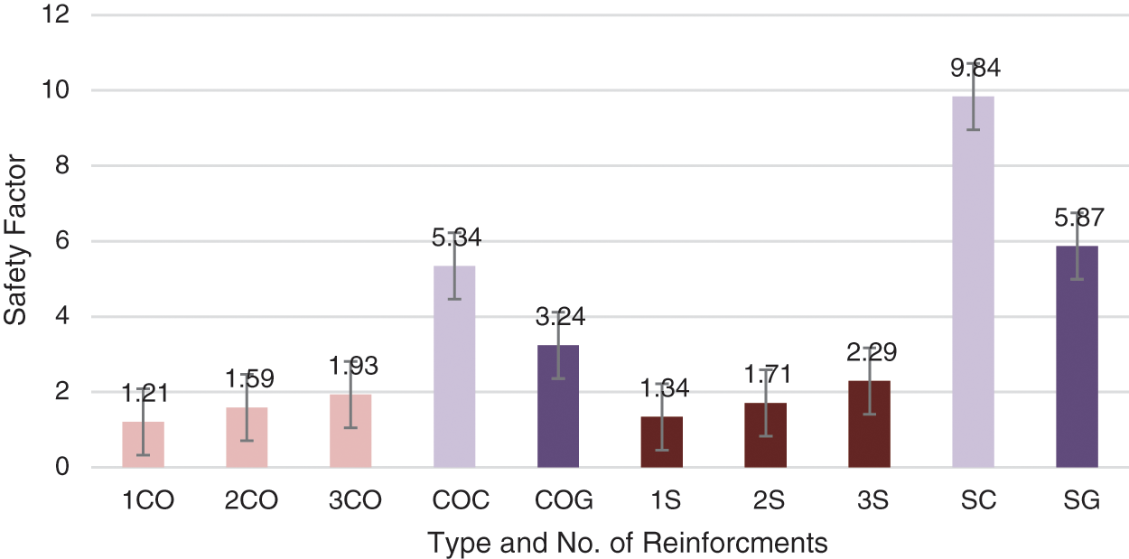
Figure 19: Numerical safety factor of composites

Figure 20: Contours of safety factor distribution of lamination composite
5.3.4 The Numerical Analysis of Deformation
The deformation investigation supplied us with information on the values and location of the overall behavior of the socket. The maximum deformation value of the socket can be seen in Lamination 1 (2 Perlon+1 Cotton+2 Perlon) equal to (9.058) mm for the model manufactured, whereas the lowest extent of total deformation can be perceived in Lamination 9 (2 Perlon+1 Sisal+1 Carbon+1 Sisal+1 Carbon+1 Sisal+2 Perlon) at (3.19) mm. Fig. 21 presented the results obtained by comparing the values of total deformation attained for all the composite samples and the affiliation between the volume fraction of these new materials and the total deformation of the specimens for all lamination. It can be revealed that total deformation declined with a growing volume fraction [32]. Note that the deformation values for the socket are acceptable when using these composite materials because the socket must deform within the range of the above values when applying the interface pressure to supply comfort to the skin of the patient [33]. From Fig. 22, it can be noted that the maximum values of total deformation were seen at the center of the lateral plane while the lowest were concentrated in the basal plane of the socket [34].
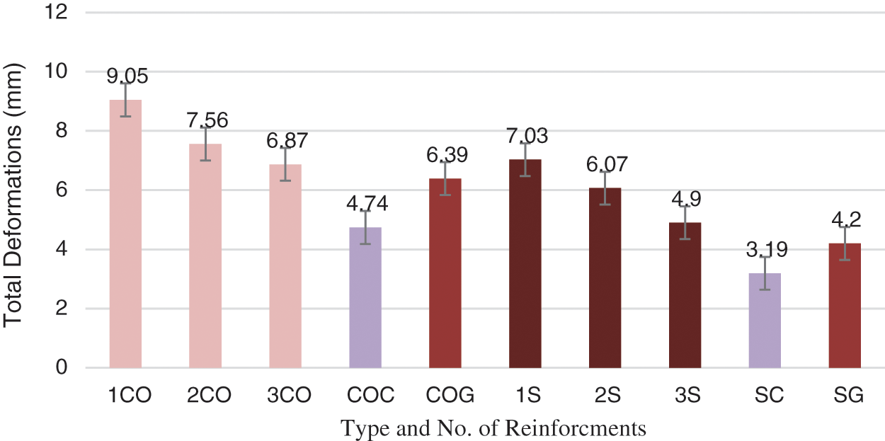
Figure 21: Contours of equivalent von-Mises Stress distribution of composite
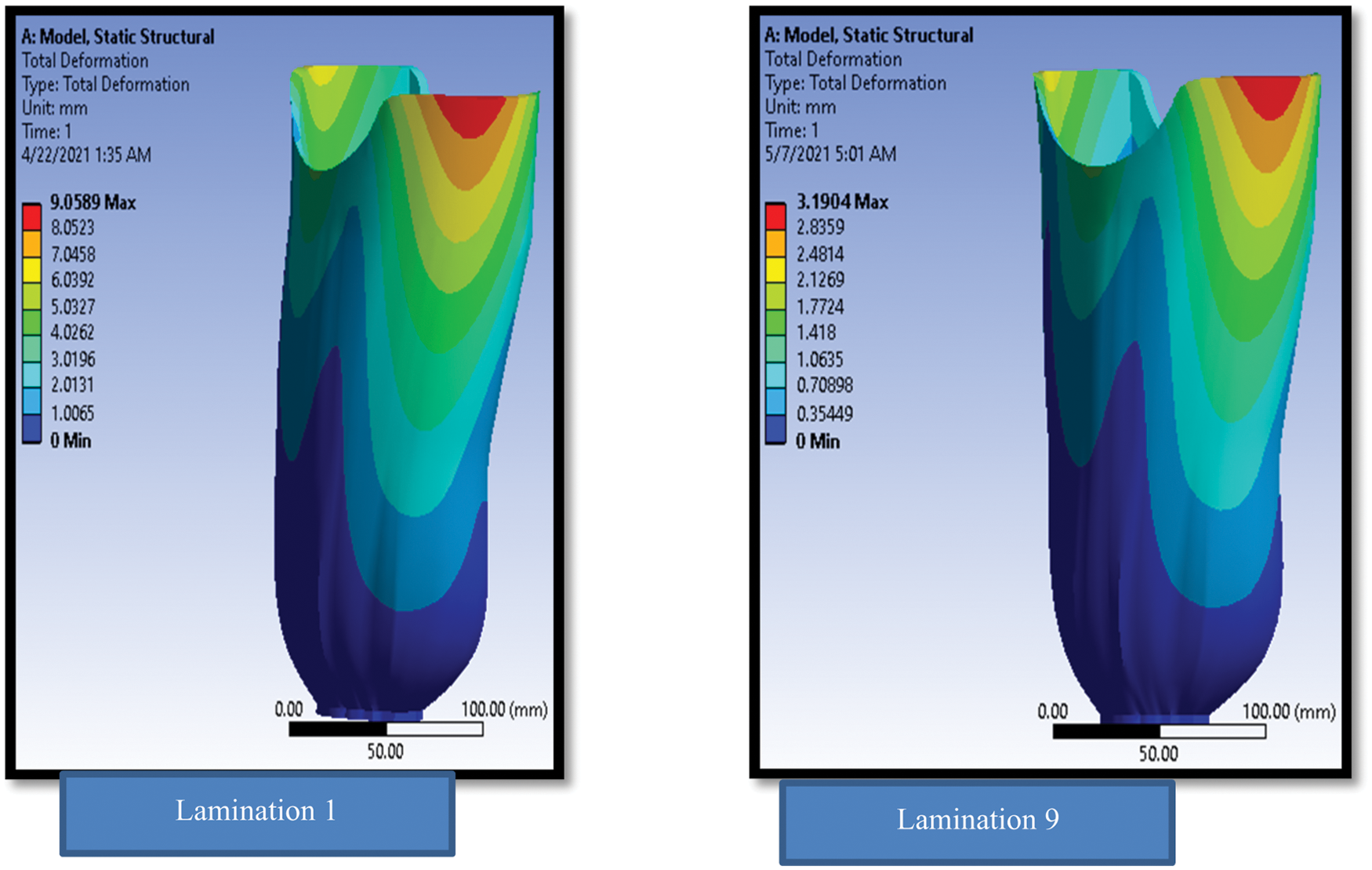
Figure 22: Contours of total deformation distribution of laminations composite
Based on the results, the prosthesis socket archetype prepared from lamination materials can be considered as a substitute artifact that could be employed by the patients with harmless and contented intent, in addition to having an optimistic influence on the usage of natural materials that are ecologically friendly and can be reused. The main findings of this study are as follows:
• The physical properties: hybrid (Cotton Glass) reinforcement having the highest density and thickness and volume fraction.
• There is a prodigious consequence in the tensile strength and modulus of elasticity of the socket with varying its material, where the (strength/density) ratio, Young’s modulus (E), and ultimate tensile strength of the stacking arrangement (4 Perlon–3 Sisal−2 Carbon fiber) where the tensile strength and modulus reach (261 MPa and 4.76 GPa), respectively.
• The highest percentage of elongation values was obtained with three cotton fibers and two layers of fiberglass, at 7.9%.
• The results showed that (sisal+Carbon reinforcement) composites offered the best experimental, numerical consequences which brand them as the outstanding contender to advance the mechanical features of the trans-tibial prosthetic socket.
Acknowledgement: The authors would like to express thanks to all the staff at the Faculty of Engineering at the University of Technology–Baghdad as well as the staff of Ibtisam Center of an Artificial Limb.
Funding Statement: The authors received no specific funding for this study.
Conflicts of Interest: The authors declare that they have no conflicts of interest to report regarding the present study.
1. Jia, X., Zhang, M., Lee, W. C. (2003). Load transfer mechanics between trans-tibia prosthetic socket and residual limb-dynamic effects. Journal of Biomechanics, 37(9), 1371–1377. [Google Scholar]
2. Goh, J. C. H., Lee, P. V. S., Chong, S. Y. (2004). Comparative study between patellar tendon bearing and pressure cast prosthetic socket. Journal of Rehabilitation Research & Development, 41, 491–502. DOI 10.1682/JRRD.2004.03.0491. [Google Scholar] [CrossRef]
3. Jweeg, M. J., Alhumandy, A., Hamzah, H. A. (2017). Material characterization and stress analysis of opening in syme prosthesis. International Journal Mechanical Mechatronics Engineering, 17. [Google Scholar]
4. Berry, D. A. (1987). Composite Materials for Orthotics and Prosthetics. Journal of Prosthetics Orthotic, 40(4), 35–43. [Google Scholar]
5. Atesalp, A. S., Erler, K., Gur, E., Solakoglu, C. (1999). Below-knee amputations as a result of land-mine injuries: Comparison of primary closure versus delayed primary closure. The Journal of Trauma: Injury, Infection, and Critical Care, 47(4), 724–727. DOI 10.1097/00005373-199910000-00018. [Google Scholar] [CrossRef]
6. Soldo, S., Puntaric, D., Petrovicki, Z. (1999). Injuries caused by antipersonnel mines in Croatian army soldiers on the east slavonia front during the 1991–1992 war in Croatia. Military Medicine, 164(2), 141–144. DOI 10.1093/milmed/164.2.141. [Google Scholar] [CrossRef]
7. Campbell, A. I., Sexton, S., Schaschke, C. J., Kinsman, H., McLaughlin, B. et al. (2012). Prosthetic limb sockets from plant-based composite materials. Prosthetics and Orthotics International, 36(2), 181–189. DOI 10.1177/0309364611434568. [Google Scholar] [CrossRef]
8. Fu, T., Zhao, J. L., Xu, K. W. (2007). The designable elastic modulus of 3-D fabric reinforced biocomposites. Materials Letters, 61(2), 330–333. DOI 10.1016/j.matlet.2006.04.057. [Google Scholar] [CrossRef]
9. Evans, S. L., Gregson, P. J. (1998). Composite technology in load-bearing orthopedic implants. Biomaterials, 19(15), 1329–42. DOI 10.1016/S0142-9612(97)00217-2. [Google Scholar] [CrossRef]
10. Marks, L. J., Michael, J. W. (2001). Artificial limbs. BMJ, 323, 732. DOI 10.1136/bmj.323.7315.732. [Google Scholar] [CrossRef]
11. Jenkins, G. M., de Carvalho, F. X. (1977). Biomedical applications of carbon fiber reinforced carbon in implanted prostheses. Carbon, 15(1), 33–37. DOI 10.1016/0008-6223(77)90071-9. [Google Scholar] [CrossRef]
12. Irawan, A. P., Sukania, I. W. (2015). Gait analysis of lower limb prosthesis with socket made from rattan fiber reinforced epoxy composites. Asian Journal of Applied Sciences, 3(1), 8–13. [Google Scholar]
13. Kadhim Oleiwi, J., Jumaah Ahmed, S. (2016). Studying the tensile and buckling for PMMA reinforced by jute fibers for prosthetic pylon. Engineering and Technology Journal, 34(1), 111–122. [Google Scholar]
14. Chiad, J. S., Tahir, M. S. (2017). Enhancement of the mechanical properties for above-knee prosthetic socket by using the bamboo fiber. International Journal of Energy and Environment, 8(4), 331–338. [Google Scholar]
15. Muhammad, S. T., Jumaa, S. C. (2017). A suggested new material to manufacture above-knee prosthetic socket using the lamination of monofilament, cotton and perlon fibers’. Al-Nahrain Journal for Engineering Sciences, 20(4), 832–837. [Google Scholar]
16. Irawan, A. P., Sukania, I. W. (2012). Tensile and impact strength of bamboo fiber reinforced epoxy composite as alternative materials for above knee prosthesis socket. Proceeding of International Conference on Sustainable Technology and Development, pp. 109–115. [Google Scholar]
17. Sukania, I. W., Irawan, A. P. (2015). Tensile strength of banana fiber reinforced epoxy composites materials. Applied Mechanics and Materials, 776, 260–263. DOI 10.4028/www.scientific.net/AMM.776.260. [Google Scholar] [CrossRef]
18. Resan, K. K., Ibrahim, Y. K., Abd Al-Razaq, I. R. (2015). Design and manufacturing of fast prosthetic below knee socket. ASME International Mechanical Engineering Congress and Exposition, Houston, Texas, USA. [Google Scholar]
19. Al-Khazraji, O. J. K., Ahmed, P. S. (2012). Tensile and fatigue characteristics of lower-limb prosthetic socket made from composite materials. International Conference on Industrial Engineering and Operations Management, Istanbul, Turkey. [Google Scholar]
20. American Sosciaty of Testing Materials. (2004). Standard Test Method for Tensile Properties of Plastics D638-03. Annual Book of ASTM Standard, New York. [Google Scholar]
21. Resan, K. K., Zeki, A. (2013). Design and Analysis of Knee Ankle Foot Orthosis (KAFO) for Paraplegia Person. Engineering and Technology Journal, 31(8), 1521–1533. [Google Scholar]
22. Kadhim, F. M., Takhakh, A. M., Chiad, J. S. (2013). Vibration Measurement and analysis of knee Ankle foot orthosis for both metal and plastic KAFO type. ASME International Mechanical Engineering Congress and Exposition, 20, 136–149. DOI 10.1115/IMECE2013-64641. [Google Scholar] [CrossRef]
23. Kadhim, F. M., Takhakh, A. M., Chiad, J. S. (2018). Design and manufacturing knee joint for smart transfemoral prosthetic. IOP Conference Series: Materials Science and Engineering, 454, 012078. DOI 10.1088/1757-899X/454/1/012078. [Google Scholar] [CrossRef]
24. Ismail, M. T., Jweeg, M. J., Resan, K. K. (2013). Study of creep-fatigue interaction in the prosthetic socket below knee. Innovative Systems Design and Engineering, 4(5), 383–394. [Google Scholar]
25. Giridharan, R., Jenarthanan, M. P. (2019). Preparation and characterization of glass and cotton fibers reinforced epoxy hybrid composites. Pigment & Resin Technology, 48(4), 272–276. DOI 10.1108/PRT-05-2018-0044. [Google Scholar] [CrossRef]
26. Noorunnisa Khanam, P., Abdul Khalil, H. P. S., Jawaid, M., Ramachandra Reddy, G., Surya Narayana, C. et al. (2010). Sisal/Carbon fiber reinforced hybrid composites: Tensile, flexural and chemical resistance properties. Journal of Polymers and the Environment, 18 (4), 727–733. DOI 10.1007/s10924-010-0210-3. [Google Scholar] [CrossRef]
27. Elanchezhian, C., Ramnath, B. V., Hemalatha, J. (2014). Mechanical behavior of glass and carbon fiber-reinforced composites at varying strain rates and temperatures. Procedia Materials Science, 6, 1405–1418. DOI 10.1016/j.mspro.2014.07.120. [Google Scholar] [CrossRef]
28. Hamad, Q. A., Alwan, M. K., Tariq, M. A. (2011). Tensile and buckling analysis of the polymer composite beam reinforced by natural jute fiber. Engineering and Technology Journal, 29(1), 129–140. [Google Scholar]
29. Hamad, Q. A., Salih, S. I., Shabab, K. M. (2010). Studying mechanical properties for polymer matrix composite material reinforced by fibers and particles. Engineering and Technology Journal, 28(4), 81–93. [Google Scholar]
30. Wilberforce, S., Hashemi, S. (2009). Effect of fiber concentration, strain rate, and weld-line on mechanical properties of injection-molded short glass fiber reinforced thermoplastic polyurethane. Journal of Materials Science, 44(5), 1333–1343. DOI 10.1007/s10853-008-3233-6. [Google Scholar] [CrossRef]
31. Kohnke, P. (2008). Ansys-11 Workbench help guide,SAS IP, Inc., Eleventh Edition. [Google Scholar]
32. Hamad, Q. A., Oleiwi, J. K., Salih, S. I. (2015). Numerically and theoretically studying of the upper composite complete prosthetic denture. Engineering and Technology Journal, 33(5), 289–307. [Google Scholar]
33. Resan, K. K., Ibrahim, Y. K., Challoob, S. H. (2015). Stress relaxation on prosthetic laminated socket materials. Journal of Engineering and Development, 20(3), 110–124. [Google Scholar]
34. Al-Khazraji, K., Oleiwi, J. K., Ahmed, P. S. (2015). Improving mechanical and fatigue characteristic of trans-tibia prosthetic socket. International Conference on Industrial Engineering and Operations Management Dubai, United Arab Emirates. [Google Scholar]


Figure 23: Analysis of von mises stress of the socket


Figure 24: Analysis of von mises strain of the socket


Figure 25: Contours of safety Factor distribution of lamination composite


Figure 26: Contours of total deformation distribution of laminations composite
 | This work is licensed under a Creative Commons Attribution 4.0 International License, which permits unrestricted use, distribution, and reproduction in any medium, provided the original work is properly cited. |