| Journal of Renewable Materials |
DOI: 10.32604/jrm.2023.020751
ARTICLE
Experimental Study of Mode-I and Mode-II Interlaminar Fracture Characteristics of Poplar LVL
1College of Civil Engineering, Yangzhou Polytechnic Institute, Yangzhou, 225127, China
2College of Civil Science and Engineering, Yangzhou University, Yangzhou, 225127, China
*Corresponding Author: Yan Liu. Email: liuyan@yzu.edu.cn
Received: 10 December 2021; Accepted: 09 February 2022
Abstract: Fracture is a common failure form of poplar laminated veneer lumber (LVL). In the present work, we performed an experimental study on the mode-I along-grain interlaminar fracture, mode-I cross-grain interlaminar fracture, and mode-II interlaminar fracture of poplar LVL. We investigated stress mechanisms, failure modes, and fracture toughness values of the different fracture types. The experimental results revealed that the crack in the mode-I along-grain interlaminar fracture specimen propagated along the prefabricated crack direction, and the crack tip broke. The mode-I cross-grain interlaminar fracture specimen had cracks in the vertical direction near the prefabricated crack. In the mode-II interlaminar fracture specimen, cracks appeared along the initial prefabricated crack direction. The load–displacement curves of these three specimens were linear in the early stage of loading. With the increase in the load, a nonlinear segment appeared before crack propagation and a descending segment appeared after crack propagation. The nonlinear segments of the mode-I along-grain interlaminar fracture and mode-II interlaminar fracture were very short, and cracks expanded quickly after their initiation, resulting in brittle fracture. The nonlinear segment of the mode-I cross-grain interlaminar fracture was long, resulting in plastic failure. The average toughness values of the mode-I along-grain interlaminar fracture, mode-I cross-grain interlaminar fracture, and mode-II interlaminar fracture were 15.43, 270.15, and 39.72 MPa·mm1/2, respectively.
Keywords: Poplar LVL; crack propagation; fracture toughness
Wood and bamboo are environmentally friendly (i.e., green) building materials. Bamboo and timber structure buildings are being vigorously promoted and applied, and many scholars have conducted a significant amount of research [1–4]. Poplar laminated veneer lumber (LVL) sheets are fabricated by hot-pressing poplar veneer. Because of its excellent physical and mechanical properties, LVL has been applied widely to wooden-structured buildings and is suitable for the development of green and prefabricated buildings [5–8]. Microscopic and macroscopic defects or damage (cracks) naturally occur in wood [9–12]. The irregular evolution of these initial defects or damage causes wood to break. Therefore, it is important to investigate the fracture mechanism of LVL to control and reduce the occurrence of accidents.
The fracture characteristics of wood have been extensively researched. In 1964, Porter [13] first applied the principles of fracture mechanics to wood materials. Based on an energy balance, a linear elastic fracture model was introduced to analyze longitudinal–tangential (LT) and longitudinal–radial (LR) plane open fractures of western white pine wood. Moreover, a new method based on the strain energy release rate was used to determine the wood fracture parameters. In 2006, Stefanie et al. [14] analyzed the fracture mechanism of wood using scanning electron microscopy and studied the microstructural evolution and fracture characteristics of wood under tensile loading. Moreover, the relationship between the fracture toughness (KIC) and fracture energy (Gf) of mode-I interlaminar fractures was studied, and the influences of the wood type, fiber orientation, density, and humidity on KIC and Gf were reported. In 1993, Fan et al. [15] conducted a three-point bending test on single-side notch specimens to explore the main factors affecting the transverse fracture toughness of fir. Some scholars [16–18] have carried out a series of studies on the effect of delamination between glulam beams and column members on their bearing capacities by applying fracture theory. In 2000, Jiang et al. [19] used a synchrotron radiation light source to observe the failure process of Chinese fir and Masson pine under tensile loading and noticed that under radial tensile loading, the wood specimens tended to grow into earlywood and latewood. Cracks appeared at the specimen boundaries and extended to the earlywood part. The crack propagation path was irregular and terminated at the cell wall. Under chordal tensile loading, a large number of cracks appeared in the wooden beam. Some scholars [20–23] have analyzed the composite fracture failure of wood from a microscopic level. Yang et al. [24] studied the failure mode and mechanism of Glulam I-shaped beams. Huang et al. [25] developed an analytical solution for DCB fibrous composite specimen tested for mode I fracture. Zhou et al. [26] studied the mode-I fracture properties of PSB composite, it was found that the fracture toughness of PSB is higher than that of commonly used woods, and their fracture behavior is similar, exhibiting quasi-brittle behavior.
Poplar LVL [27,28] is a load-bearing wooden material that can be used in wooden-structure buildings. Fracture is a common failure form of poplar LVL; however, its fracture characteristics have been rarely investigated. In the present work, we experimentally explored the mode-I (open type) and mode-II (slip type) interlaminar fracture characteristics of LVL. In addition, we investigated the force mechanisms, failure modes, and fracture toughness values of different fracture types.
2.1 Material Preparation and Pretreatment
2.1.1 Preparation of Mode-I Along-Grain Interlaminar Fracture Specimens
Italian poplar LVL was supplied by Jiangsu Siyang Jiuhe Wood Industry Co., Ltd., China, the moisture content was 12.8%, and the density was 0.576 g/cm3. We prepared and tested 10 sets of specimens according to the compact tensile method (No. 1-1 to 1-10). All specimens were sawed from the same Italian poplar LVL wood sheets with a thickness (B) of 40 mm. A crack opening in each specimen was created by a 2-mm-thick saw blade, and the crack tip was then extended to the specified position using a sharp blade. Based on the GB/T4161-2007 standard (Metallic Material Plane Strain Fracture Toughness KIC Test Method), the crack length was set between 0.45 W and 0.55 W, where W is the specimen width. The specific dimensions of the mode-I along-grain interlaminar fracture specimens are presented in Fig. 1a.
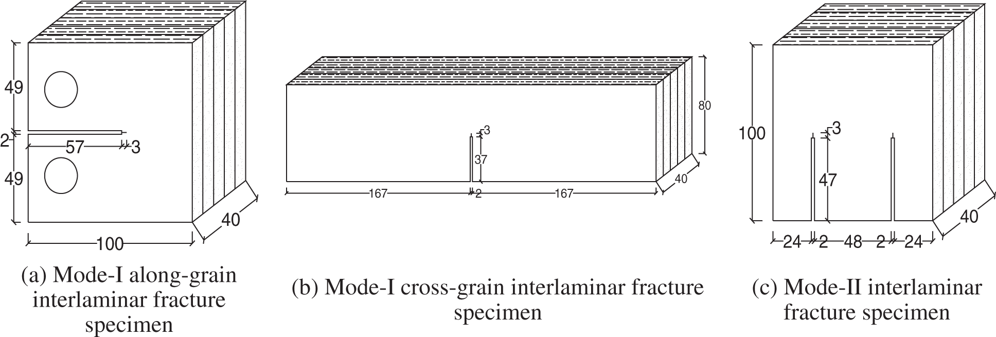
Figure 1: Specimen dimensions (in mm)
2.1.2 Preparation of Mode-I Cross-Grain Interlaminar Fracture Specimens
We prepared and tested 10 sets of specimens according to the three-point bending method (No. 2-1 to 2-10) [29]. All specimens were sawed from the same LVL wooden sheet with a thickness (B) of 40 mm. The dimensions of the mode-I cross-grain interlaminar fracture specimens are displayed in Fig. 1b, where the pre-crack length at the middle of the specimen length a and a/W = 0.45–0.55. When a/W = 0.5, the nominal value of a was 40 mm.
2.1.3 Preparation of Mode-II Interlaminar Fracture Specimens
We used the compact symmetric shear specimen designed by Jones and Chisholm in 1975 to calculate the mode-II interlaminar fracture toughness of Italian poplar LVL [30]. All specimens (No. 3-1 to 3-10) were sawed from the same LVL wooden sheet with a thickness (B) of 40 mm. The dimensions of the mode-II interlaminar fracture specimens are shown in Fig. 1c.
For these experiments, we used a D-54518 Niersbach sliding table saw, an MBS240/E mini band saw machine, an No27070 mini sliding table saw, a BS423S electronic balance (Shanghai Meiyingpu Instrument Manufacturing Co., Ltd., Shanghai, China), a WDW-100 electronic universal testing machine (Changchun Xinte Testing Machine Co., Ltd., China), and a 150T Vernier caliper (Shanghai Menet Industrial Co., Ltd., Shanghai, China).
The mode-I and mode-II fracture toughness values of poplar LVL were measured according to ASTM E399(09), Standard Test Method for Linear-Elastic Plane-Strain Fracture Toughness KIC of Metallic Materials [31], and GB/T4161-2007, Metallic Material Plane Strain Fracture Toughness KIC Test Method.
In the mode-I along-grain fracture toughness tests, we used the displacement-control loading method, with a loading speed of 0.5 mm/min. In the mode-I cross-grain fracture toughness tests, the uniform loading method was adopted with a loading speed of 1.5 mm/min and a support distance of S = 4 W. In the mode-II interlaminar fracture toughness tests, a shear load was applied to the specimens. The specimens were loaded by the displacement control method with a loading speed of 0.5 mm/min. The test devices for the different fracture toughness tests are displayed in Fig. 2.
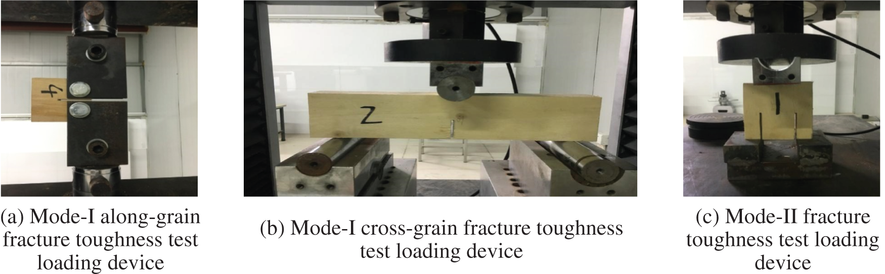
Figure 2: Test loading devices
3.1.1 Mode-I Along-Grain Interlaminar Fracture
During the loading process, the front end of the crack did not expand significantly. With the continuous increase in the load, the deformation of the specimen gradually increased and was accompanied by a slight noise. The crack expanded along the grain direction, and consequently, with a sudden abnormal noise, the crack tip ruptured, and the load dropped sharply. The poplar LVL was made of thick veneer laminated in the along-grain direction. Therefore, the crack propagated in the along-grain direction. The failure form of the mode-I along-grain interlaminar fracture specimens is displayed in Fig. 3a.
3.1.2 Mode-I Cross-Grain Interlaminar Fracture
During the loading process, no significant crack expansion occurred in the early stage of loading. As the load continued to increase, the crack began to expand with a slight cracking sound and appeared near the prefabricated crack. Small cracks appeared along the grain direction, causing irregular breakage of the specimen along the direction of the adhesive layer (Fig. 3b). Crack propagation occurred more easily in the grain direction than in the cross grain direction, because the longitudinal strength was controlled primarily by the adhesive force of the adhesive and the transverse strength was determined by the strength of the wood fibers. Thus, the longitudinal strength was much lower than the lateral strength.
3.1.3 Mode-II Interlaminar Fracture
No crack propagation occurred at the crack front in the early stage of loading. As the load continued to increase, no significant deformation occurred in the specimen; however, a slight noise was generated. When the load reached a critical value, a crack appeared at the tip of the specimen along the grain direction (Fig. 3c). Hence, the bonding between the wood fibers along the initial prefabricated crack direction of the mode-II interlaminar fracture specimen weakened, and the crack continued to expand.
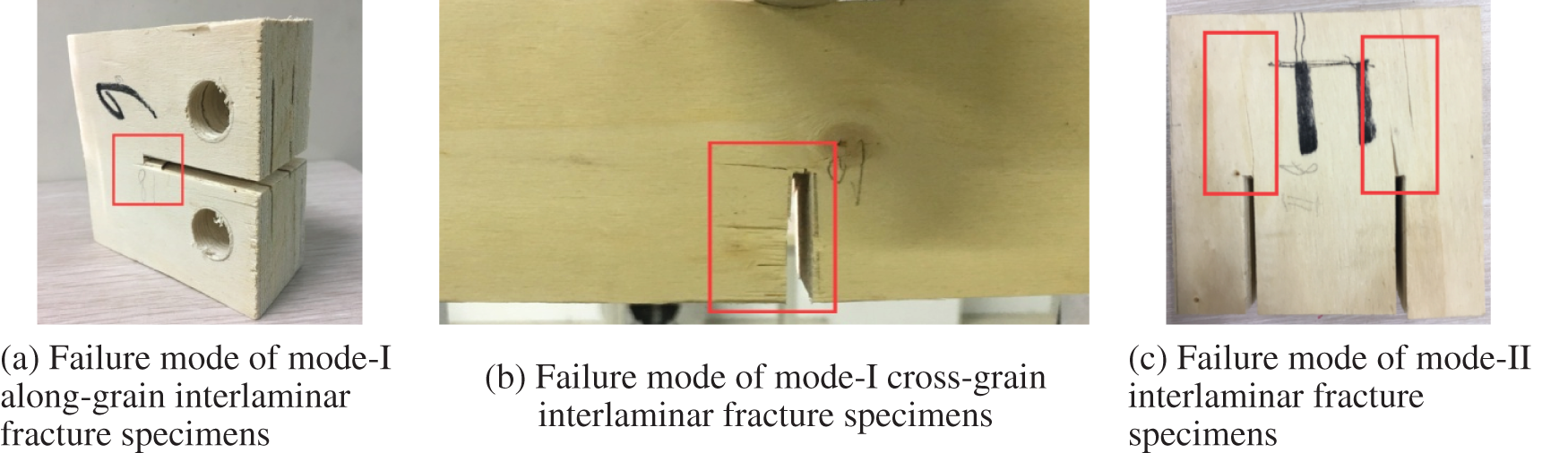
Figure 3: Failure modes
3.2.1 Mode-I Along-Grain Interlaminar Fracture
Fig. 4 displays the load–displacement curve of a mode-I along-grain interlaminar fracture specimen. The load–displacement curve was linear in the early stage of loading. As the load increased, a nonlinear segment appeared before crack propagation. A fracture process zone was generated at the crack tip before crack propagation. This fracture process zone absorbed some of the energy and enhanced the toughness of the material. After crack propagation, a descending section appeared in the load–displacement curve, and the crack propagated rapidly in a short time; thus, the bearing capacity of the specimen decreased significantly because of brittle fracture [32].
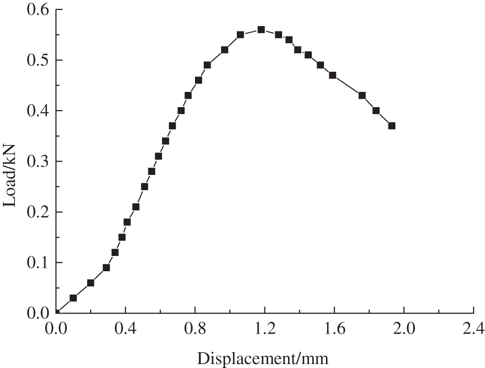
Figure 4: Load–displacement curve of mode-I along-grain interlaminar fracture specimen
3.2.2 Mode-I Transverse-Grain Interlaminar Fracture
Fig. 5 shows the load–displacement curve of a mode-I transverse-grain interlaminar fracture specimen. The load–displacement curve was linear in the early stage of loading. As the load increased, a slight fiber fracture sound was generated, and the load–displacement curve entered a nonlinear stage (the load was called the initiation load). Subsequently, small lateral cracks appeared at the prefabricated crack tip, and the number of cracks continued to increase followed by a loud cracking sound. Consequently, the specimen ruptured, and the load dropped sharply. Compared with the along-grain interlaminar fracture specimen, the nonlinear segment of the transverse-grain interlaminar fracture specimen was longer. The transverse-grain interlaminar fracture continued to bear larger loads after cracking.
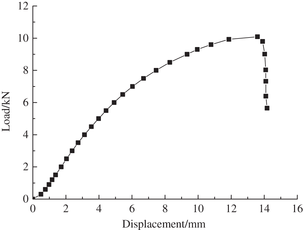
Figure 5: Load–displacement curve of mode-I cross-grain interlaminar fracture specimens
3.2.3 Mode-II Interlaminar Fracture
Fig. 6 displays the load–displacement curve of a mode-II interlaminar fracture specimen. The load–displacement curve was linear in the early stage of loading. As the load increased, a short nonlinear section appeared before crack propagation. After crack propagation, a descending section appeared, and the crack propagated rapidly in a short period. The rapid decline in the bearing capacity of the specimen occurred because of brittle fracture.
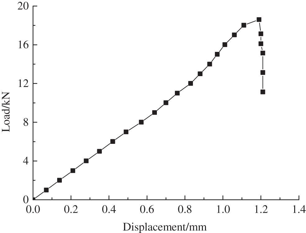
Figure 6: Load–displacement curve of mode-II interlaminar fracture specimens
The intensity of the stress field near the crack tip was measured by the stress intensity factor, and the stress intensity factor in the critical state of crack propagation can be called the fracture toughness [33–35].
3.3.1 Mode-I Along-Grain Interlaminar Fracture
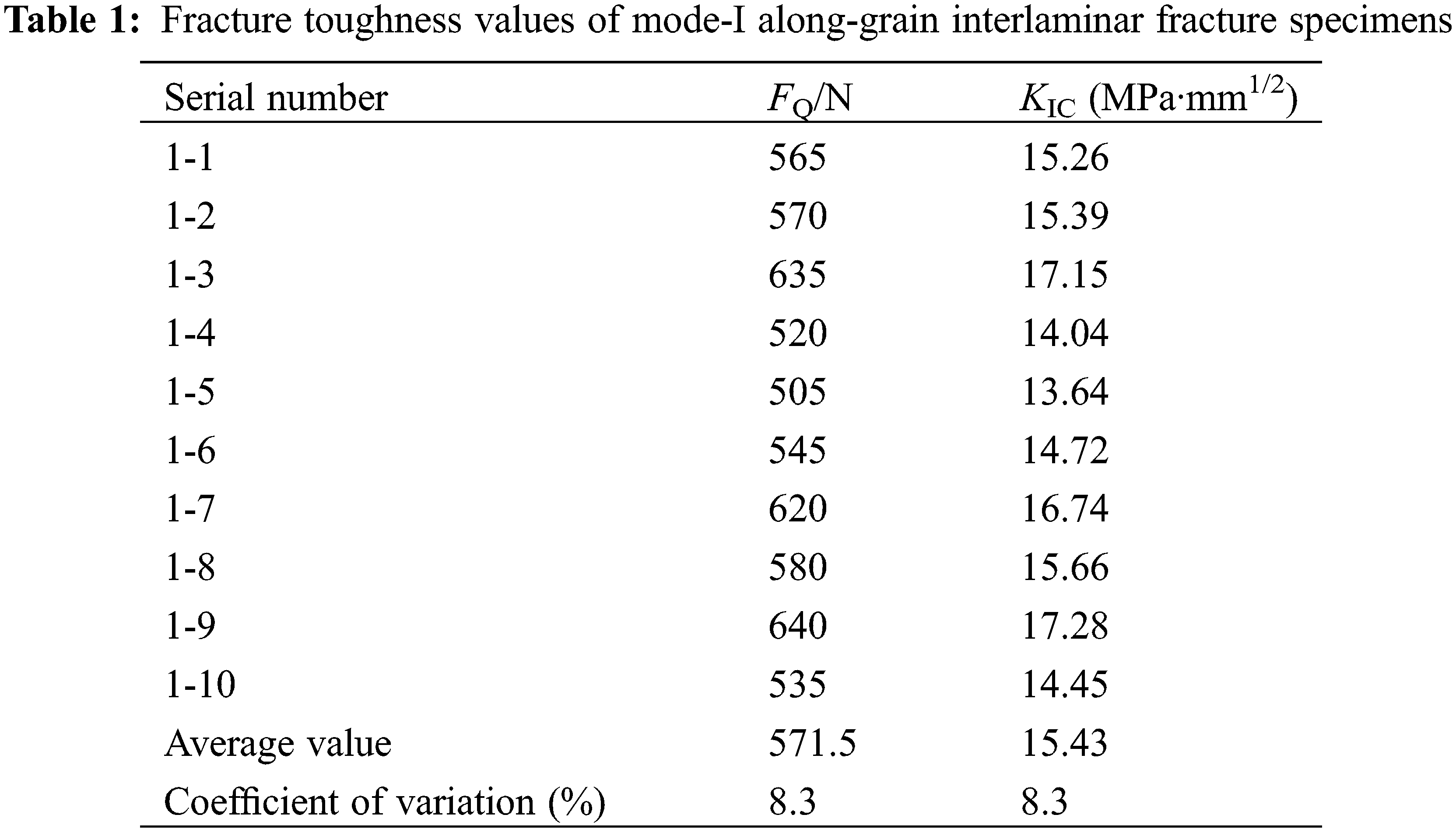
The fracture toughness values of the mode-I along-grain interlaminar fracture specimens were calculated as follows:
where a is the length of the prefabricated crack (40 mm), W is the effective width of the test piece (80 mm), B is the thickness of the test piece (40 mm), and FQ is the load when the specimen began to crack.
Moreover, f(a/W) was calculated as follows:
The value of f(a/W) was calculated as 9.66.
The fracture toughness values of all the test pieces are listed in Table 1. The fracture toughness of the mode-I along-grain interlaminar fracture specimens fluctuated in the range of 13.64 to 17.28 MPa·mm1/2, with an average value of 15.43 MPa·mm1/2 and a variation coefficient of <20%, indicating that the calculated data were valid. Jiang et al. [36] calculated the interlaminar fracture toughness values of Chinese fir and Masson pine as 4.812 and 9.667 MPa·mm1/2, respectively. Therefore, the interlaminar fracture toughness of Italian poplar was 3.2 times that of Chinese fir and 1.6 times that of Masson pine.
3.3.2 Mode-I Cross-Grain Interlaminar Fracture
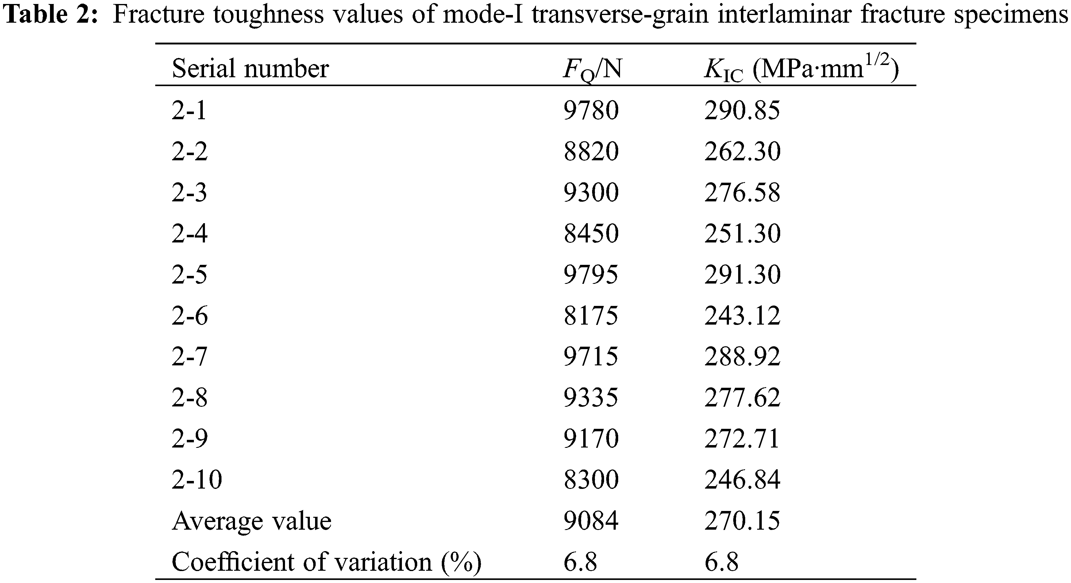
The fracture toughness values of the mode-I cross-grain interlaminar fracture specimens were calculated as follows:
where a is the length of the prefabricated crack (40 mm), W is the effective width of the test piece (80 mm), B is the thickness of the test piece (40 mm), and FQ is the load when the specimen began to crack.
Moreover, f(a/W) was calculated as follows:
The value of f(a/W) was calculated as 2.66.
The fracture toughness values of all the specimens are presented in Table 2. The fracture toughness values of the mode-I transverse-grain interlaminar fracture specimens fluctuated in the range of 243.12 to 291.30 MPa·mm1/2 with an average value of 270.15 MPa·mm1/2 and a variation coefficient of less than 20%, indicating that the obtained data were valid. Therefore, the fracture toughness values of the mode-I transverse-grain interlaminar fracture specimens were 17.5 times those of the along-grain specimens.
3.3.3 Mode-II Interlaminar Fracture
The fracture toughness values of the mode-II interlaminar fracture specimens were calculated as follows:
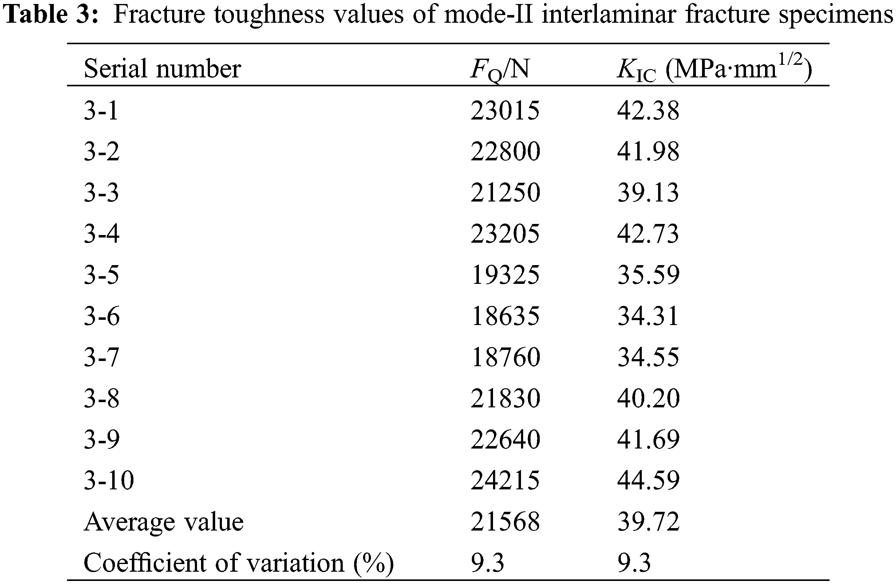
where a is the length of the prefabricated crack (50 mm), B is the thickness of the test piece (40 mm), H is the tooth width (48 mm), and FQ is the load when the specimen began to crack.
The fracture toughness values of all the specimens are listed in Table 3. The fracture toughness of the mode-II interlaminar fracture specimens fluctuated in the range of 34.31 to 44.59 MPa·mm1/2, with an average value of 39.72 MPa·mm1/2 and a variation coefficient of less than 20%, indicating that the obtained data were valid.
The results of our study showed the following conclusions:
1. The crack in the mode-I along-grain interlaminar fracture specimen expanded along the prefabricated crack direction, and the crack tip fractured. The mode-I cross-grain interlaminar fracture specimen had small cracks along the grain direction near the prefabricated crack. Therefore, crack propagation was easier in the grain direction than in the transverse grain direction. The longitudinal strength was controlled mainly by the adhesive force of the adhesive, whereas the transverse strength was determined by the strength of the Italian poplar wood fibers. Thus, the longitudinal strength was much lower than the transverse strength. In the mode-II interlaminar fracture specimen, cracks appeared along the initial prefabricated crack direction.
2. The load–displacement curves of the three specimens were linear in the preloading stage. With the increase in the load, a nonlinear segment appeared before crack propagation. A fracture process zone was generated at the crack tip before crack propagation. This fracture process zone absorbed some of the energy and enhanced the toughness of the material. After crack propagation, a descending section appeared and cracks propagated rapidly in a short time. In turn, the bearing capacity of the specimen decreased greatly. The nonlinear segments of the mode-I along-grain interlaminar fracture and mode-II interlaminar fracture were very short, and cracks propagated quickly after their initiation, resulting in brittle fracture. The nonlinear section of the mode-I transverse interlaminar fracture was longer, resulting in plastic failure.
3. The fracture toughness values of the mode-I along-grain interlaminar fracture specimens fluctuated in the range of 13.64 to 17.28 MPa·mm1/2, with an average value of 15.43 MPa·mm1/2. The fracture toughness values of the mode-I transverse interlaminar fracture specimens fluctuated in the range of 243.12 to 291.30 MPa·mm1/2, with an average value of 270.15 MPa·mm1/2. The fracture toughness values of the mode-II interlaminar fracture specimens fluctuated in the range of 34.31 to 44.59 MPa·mm1/2, with an average value of 39.72 MPa·mm1/2.
Acknowledgement: All authors contributed equally to this work.
Funding Statement: We thank the National Natural Science Foundation of China (Grant No. 51878590), the Jiangsu Provincial Department of Housing and Construction (Grant Nos. 2019ZD092, 2020ZD40, 2020ZD42), and the Sixth Phase of “333 Project” Training Objects in Jiangsu Province and Jiangsu Province High-Level Talent Selection Training (Grant No. JNHB-127) for their financial support.
Conflicts of Interest: The authors declare that they have no conflicts of interest to report regarding the present study.
References
1. Yang, L. T., Lou, Z. C., Han, X., Liu, J., Wang, Z. X. et al. (2020). Fabrication of a novel magnetic reconstituted bamboo with mildew resistance properties. Materials Today Communications, 23, 101086. DOI 10.1016/j.mtcomm.2020.101086. [Google Scholar] [CrossRef]
2. Lou, Z. C., Yuan, T. C., Wang, Q. Y., Wu, X. W., Hu, S. H. et al. (2021). Fabrication of crack-free flattened bamboo and its macro-/micro- morphological and mechanical properties. Journal of Renewable Materials, 9(5), 959–977. DOI 10.32604/jrm.2021.014285. [Google Scholar] [CrossRef]
3. Lou, Z. C., Wang, Q. Y., Sun, W., Zhao, Y. H., Wang, X. Z. et al. (2021). Bamboo flattening technique: A literature and patent review. European Journal of Wood and Wood Products, 79(5), 1035–1048. DOI 10.1007/s00107-021-01722-1. [Google Scholar] [CrossRef]
4. Wang, T., Wang, Z. Q., Yang, Y., Zhou, J. H. (2022). Acoustic emission characteristics of different bamboo and wood materials in bending failure process. Journal of Renewable Materials, 10(2), 527–540. DOI 10.32604/jrm.2022.017955. [Google Scholar] [CrossRef]
5. Mikael, F. (1997). Effect of size on the bending strength of laminated veneer lumber. Wood Science and Technology, 31(6), 399–413. DOI 10.1007/BF00702562. [Google Scholar] [CrossRef]
6. Shukla, S. R., Kamdem, D. P. (2008). Properties of laminated veneer lumber (LVL) made with low density hardwood species: Effect of the pressure duration. Holzals Roh-und Werkstoff, 66(2), 119–127. DOI 10.1007/s00107-007-0209-1. [Google Scholar] [CrossRef]
7. Shukla, S. R., Kamdem, D. P. (2009). Properties of laboratory made yellow poplar (Liriodendron tulipifera) laminated veneer lumber: Effect of the adhesives. European Journal of Wood and Wood Products, 67(4), 397–405. DOI 10.1007/s00107-009-0333-1. [Google Scholar] [CrossRef]
8. Ido, H., Nagao, H., Kato, H., Miyatake, A., Hiramatsu, Y. (2010). Strength properties of laminated veneer lumber in compression perpendicular to its grain. Journal of Wood Science, 56(5), 422–428. DOI 10.1007/s10086-010-1116-3. [Google Scholar] [CrossRef]
9. Obataya, E., Kitin, P., Yamauchi, H. (2007). Bending characteristics of bamboo (Phyllostachys pubescens) with respect to its fiber-foam composite structure. Wood Science and Technology, 41(5), 385–400. DOI 10.1007/s00226-007-0127-8. [Google Scholar] [CrossRef]
10. Ando, K., Hirashima, Y., Sugihara, M., Hirao, S., Sasaki, Y. (2006). Microscopic processes of shearing fracture of old wood, examined using the acoustic emission technique. Journal of Wood Science, 52(6), 483–489. DOI 10.1007/s10086-005-0795-7. [Google Scholar] [CrossRef]
11. Yoshihara, H., Ohta, M. (2000). Measurement of mode II fracture toughness of wood by the end-notched flexure test. Journal of Wood Science, 46(4), 273–278. DOI 10.1007/BF00766216. [Google Scholar] [CrossRef]
12. Reiterer, A., Tschegg, S. (2002). The influence of moisture content on the mode I fracture behaviour of sprucewood. Journal of Materials Science, 34(20), 417–430. DOI 10.1023/A:1020610231862. [Google Scholar] [CrossRef]
13. Porter, A. W. (1964). On the mechanics of fracture in wood. https://www.proquest.com/openview/575d64dcde7d1cef335ebead083a86db/1?pq-origsite=gscholar&cbl=18750&diss=y. [Google Scholar]
14. Stanzl, T., Stefanie, E. (2006). Microstructure and fracture mechanical response of wood. International Journal of Fracture, 139, 495–508. DOI 10.1007/s10704-006-0052-0. [Google Scholar] [CrossRef]
15. Fan, W. Y., Xu, H., Gong, M. (1993). The study of measuring wood fracture toughness KIC. Journal of Nanjing Forestry University, 17(3), 80–82. [Google Scholar]
16. Adam, C., Heuer, R., Jeschko, A. (1997). Flexural vibration of elastic composite beam with interlayer slip. Acta Mechanica, 125(1–4), 17–30. DOI 10.1007/BF01177296. [Google Scholar] [CrossRef]
17. Cas, B., Saje, M., Planinc, I. (2007). Buckling of layered wood columns. Advances in Engineering Software, 38, 286–597. DOI 10.1016/j.advengsoft.2006.08.021. [Google Scholar] [CrossRef]
18. Song, H., Wang, Z. Q., Gong, Y. C., Li, L., Zhou, J. H. et al. (2022). Low-cycle fatigue life and duration-of-load effect for hybrid CLT fabricated from lumber and OSB. Journal of Building Engineering, 46(3), 103832. DOI 10.1016/j.jobe.2021.103832. [Google Scholar] [CrossRef]
19. Jiang, Z. H., Ren, H. Q., Hu, Y. G., Liu, G., Kan, Y. (2000). Study on the process of wood fracture. Nuclear Techniques, 23(8), 572–576. DOI 10.3321/j.issn.0253-3219.2000.08.014. [Google Scholar] [CrossRef]
20. Yang, X. J., Que, Z. L., Sun, Y. F. (2014). Model-I interlaminar fracture toughness of CFRP reinforced wood composites. Journal of Northwest Forestry University, 29(4), 198–202. DOI 10.3969/j.issn.1001-7461.2014.04.35. [Google Scholar] [CrossRef]
21. Dong, H. P., Li, M. (2020). Wood acoustic emission event identification based on instantaneous frequency and damage monitor. Journal of Northwest Forestry University, 35(2), 229–234. DOI 10.3969/j.issn.1001-7461.2020.02.35. [Google Scholar] [CrossRef]
22. Li, X. S., Deng, T. T., Wang, M. H., Li, M. (2021). Linear positioning method of acoustic emission source of wood fracture based on wavelet spectral whitening and adaptive wavelet reconstruction. Journal of Northwest Forestry University, 36(3), 218–224. DOI 10.3969/j.issn.1001-7461.2021.03.32. [Google Scholar] [CrossRef]
23. Kamali, M. T., Shodja, H. M. (2014). An accurate semi-analytical method for an arbitrarily oriented edge or interior crack in an anisotropic homogeneous elastic solid. European Journal of Mechanics-A/Solids, 45, 133– 142. DOI 10.1016/j.euromechsol.2013.11.011. [Google Scholar] [CrossRef]
24. Yang, R. Y., Hong, C. K., Zhang, X. F., Yuan, Q., Sun, Y. F. (2020). Experimental research on structural behaviors of glulam I-beam with a special-shaped section. Journal of Renewable Materials, 8(2), 113–132. DOI 10.32604/jrm.2020.08190. [Google Scholar] [CrossRef]
25. Huang, D. S., Sheng, B. L., Shen, Y. R., Chui, Y. H. (2018). An analytical solution for double cantilever beam based on elastic-plastic bilinear cohesive law: Analysis for mode I fracture of fibrous composite. Engineering Fracture Mechanics, 193(75), 66–76. DOI 10.1016/j.engfracmech.2018.02.019. [Google Scholar] [CrossRef]
26. Zhou, A. P., Huang, Z. R., Shen, Y. R., Huang, D. S., Xu, J. N. (2018). Experimental investigation of mode-I fracture properties of parallel strand bamboo composite. BioResources, 13(2), 3905–3921. DOI 10.15376/biores.13.2.3905-3921. [Google Scholar] [CrossRef]
27. Zhou, Z. R., Zhao, M. C., Wang, Z., Guan, X. (2014). Correlation of the modulus of elasticity among poplar log, veneer and LVL based on the stress wave method. Journal of Northwest Forestry University, 29(3), 188–193. DOI 10.3969/j.issn.1001-7461.2014.03.38. [Google Scholar] [CrossRef]
28. Ding, P. R. (2018). Experimental study on flexural performance of polar laminated veneer lumber box beam (Master’s Thesis). Yanghzou University, China. [Google Scholar]
29. King, M. J., Sutherland, I. J., Le-Ngoc, L. (1999). Fracture toughness of wet and dry Pinusradiate. HolzalsRoh-und Werkstoff, 57(4), 235–240. DOI 10.1007/s001070050048. [Google Scholar] [CrossRef]
30. Jones, D. L., Chisholm, D. B. (1975). An investigation of the edge-sliding mode in fracture mechanics. Engineering Fracture Mechanics, 7(2), 261–270. DOI 10.1016/0013-7944(75)90007-7. [Google Scholar] [CrossRef]
31. American Society for Testing and Materials Standard (2014). D-7905 Standard test method for determination of the mode II interlaminar fracture toughness of unidirectional fiber-reinforced polymer matrix composites. Philadephia, PA, USA: ASTM. [Google Scholar]
32. Lou, Z. C., Han, X., Liu, J., Ma, Q. L., Yan, H. et al. (2021). Nano-Fe3O4/bamboo bundles/phenolic resin oriented recombination ternary composite with enhanced multiple functions. Composites Part B, 226, 109335. DOI 10.1016/j.compositesb.2021.109335. [Google Scholar] [CrossRef]
33. Sih, G. C., Paris, P. C., Irwin, G. R. (1965). On cracks in rectilin-early anisotropic bodies. International Journal of Fracture Mechanics, 1(3), 189–203. DOI 10.1007/BF00186854. [Google Scholar] [CrossRef]
34. Xu, S. L., Reinhardt, H. W., Gappoev, M. (1996). Mode II fracture testing method for highly orthotropic materials like wood. International Journal of Fracture, 75(3), 185–214. DOI 10.1007/BF00037082. [Google Scholar] [CrossRef]
35. Kretschmann, D. E. (2010). Mechanical properties of wood: USDA forest service general report FPL-GTR-190. Madison, USA: Wisconsin Forest Products Laboratory. [Google Scholar]
36. Ren, H. Q., Jiang, Z. H., Shao, Z. P. (2001). Fracyure toughness of plantation timber of Chinese fir and masson pine. China Wood Industry, 15(1), 13–14. DOI 10.19455/j.mcgy.2001.01.004. [Google Scholar] [CrossRef]