| Journal of Renewable Materials |
DOI: 10.32604/jrm.2023.022030
ARTICLE
Preparation of Eco-Friendly High-Performance Manganese Dioxide Supercapacitors by Linear Sweep Voltammetry
1College of Optoelectronic Engineering, Chengdu University of Information Technology, Chengdu, 610225, China
2College of Intelligent Manufacturing, Sichuan University of Arts and Science, Dazhou, 635000, China
*Corresponding Author: Dingyu Yang. Email: yangdingyu@cuit.edu.cn
#These authors contributed equally to this work
Received: 18 February 2022; Accepted: 13 April 2022
Abstract: In this paper, the non-polluting, non-toxic, and eco-friendly material-MnO2 electrodes were deposited on three-dimensional porous nickel (Ni) foam by linear sweep voltammetry, and the entire electrodeposition process did not require sintering of the material, which was fast and convenient while avoiding unnecessary energy consumption and thus was environmentally friendly. Scanning electron microscopy (SEM) and transmission electron microscopy were used to examine the surface and microscopic characteristics of each sample (TEM). Chronoamperometry (CA), cyclic voltammetry (CV), galvanostatic charge/discharge (GCD), and electrochemical impedance spectroscopy (EIS) were then used to determine the electrochemical characteristics of the manufactured samples. The result suggests that the MnO2-sv80 electrode sample at a scan rate of 80 mV/s−1 has excellent performance for the supercapacitor electrode. The specific capacitance was as high as 531.4 F g−1 at a current density of 1 A g−1 and remained at 223.2 F g−1 at an ultra-high current density of 20 A g−1, with capacitance retention of 42%.
Keywords: MnO2; supercapacitor; nanorods; nanospheres; high capacitance; green technology
The discovery and consumption of fossil fuels have contributed to rapid social development. However, the rapid economic growth has brought about increasingly severe environmental pollution. The goals of peak carbon dioxide emissions and carbon neutrality have triggered a human desire for clean energy. Solar energy and wind energy are high-quality clean energy sources. However, they are often unstable sources due to geographical factors and weather. As a result of this wave of the energy revolution, new, green, safe, and efficient energy storage systems (ESS) have become a hot research and development topic [1–5]. With the development of the new energy industry, energy storage technology also faces significant challenges. For example, in the new energy vehicle industry, to improve the efficiency of vehicle energy utilization, a significant amount of kinetic energy needs to be recovered while braking or parking, which requires energy storage equipment to provide ultra-high power density and requires the system to have a long service life, which traditional energy storage equipment cannot meet the requirements. As a novel energy storage device resembling a cross between a capacitor and a battery, the supercapacitor has many advantages, such as long service life, short charging time, high cycle efficiency, and good temperature characteristics (stable performance at safe operating temperatures). Combining with conventional energy storage devices, the supercapacitor can form a new efficient and eco-friendly energy storage system, compensating for power density and cycle life shortcomings. This system is widely used in different fields, including portable electronics, smart grids, and hybrid vehicles [6–8]. Supercapacitors are classified according to their charge storage method into two categories: electrochemical double-layer capacitors (EDLCs) and pseudocapacitors (PCs) [9,10]. EDLCs often use carbon materials as electrodes, and the energy storage process generally does not involve chemical reactions. EDLCs mainly rely on the rapid adsorption/desorption of pure electrostatic charge on the surface of the electrode for energy storage. Thus, EDLCs usually have a super high-power density, excellent multiplicative performance, and low energy density. On the other hand, PCs energy storage mainly relies on a highly reversible redox reaction between the electrode materials and the electrolyte interfaces, and it has a higher energy density than EDLCs [11]. Currently, the electrode materials commonly used in PCs include metal oxides and conducting polymers such as polypyrrole, nickel oxide, and manganese oxide [12]. However, the cyclic electrochemical reactions bring significant volume changes, resulting in damage to the electrode material structure, thus affecting stability and cycling performance [13].
Electrode materials are the core components directly affecting the performance of supercapacitors [14]. MnO2 has been extensively explored as a supercapacitor electrode material owing to its plentiful resources, cheap cost, ease of synthesis, broad potential window, and non-polluting and non-toxic properties [15–25]. Additionally, MnO2 nanoparticles have a large surface area, which enables additional redox reaction sites when forming electric double-layer capacitors (EDLCs) to achieve high pseudo-capacitances (PCs), resulting in a theoretical specific capacitance of MnO2 of 1370 F g−1 [26–29]. The conventional preparation process of MnO2 electrode materials is mainly based on an approach bonding MnO2 powders or films to the collector with the help of conductive agents and binders after the synthesis of MnO2 powders or films by sol-gel, co-precipitation, and hydrothermal methods. However, the use of a binder and conductive substance not only prevents electron transmission, ion diffusion, and electrode size expansion, but also occupies the void of porous MnO2, blocking the electrode reaction. Several studies have demonstrated that only 9% of Mn atoms of conventional MnO2 powder electrodes are engaged in the electrode reaction process [30], which completely contradicts our expectation that the device should be efficient and eco-friendly. Among numerous methods for preparing MnO2 nanomaterials, the electrochemical method has the advantages of low cost, short time, as well as no need to introduce extra binders and conductive agents. The electrochemical method has been proved to be an efficient approach to improving electrode materials’ electrochemical properties. Additionally, MnO2 electrode reactions often take place near the material’s surface or inside the Shallow-layer bulk phase with a thickness less than 500 nm [31]. The electrochemical deposition approach could help better control the thickness of the film, avoiding needless waste of materials while improving the energy storage efficiency, thus achieving the eco-friendly purpose. Moreover, the film thickness can be well controlled by electrochemical deposition. Additionally, electrodeposition may directly generate a three-dimensional hierarchical structure, most notably by the electrodeposition of nanomaterials on a three-dimensional porous skeleton substrate. This technique increases the material’s specific surface area, hence raising the rate of surface response.
Combining the advantages of MnO2 in supercapacitor electrodes with the advantages of the electrochemical deposition method, such as its fast results, green and low-carbon features, and no need to introduce conductive agents, this paper presents a method of ultrasonic-assisted preparation of the non-polluting, non-toxic and high-performance nano-MnO2 electrode material on three-dimensional porous nickel (Ni) foam by linear sweep voltammetry with manganese acetate and sodium sulfate as raw materials.
2.1 Electrode Green Preparation
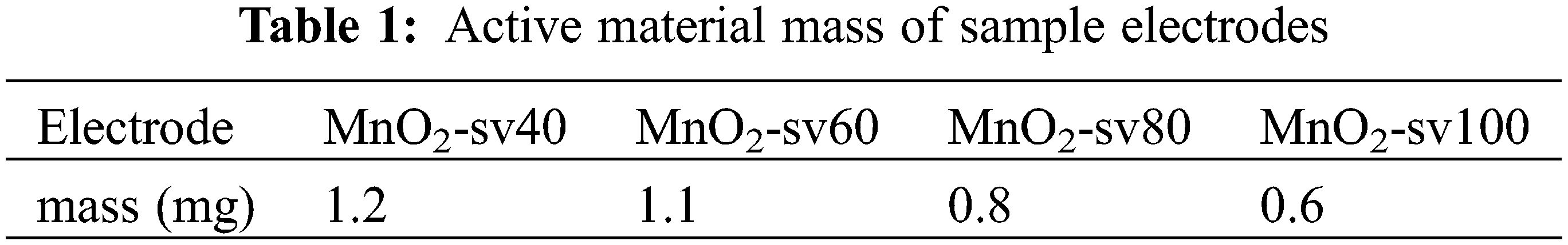
For 15 min, Nickel foam (110 PPI, 1 mm thickness, 350 g m−2, 1.0 × 1.5 cm−2) was submerged in a solution of hydrochloric acid, ethanol, and deionized water to remove any oxides or impurities from the substrate surface [32]. After drying, they were weighed, and their weights were recorded. The deposition of manganese dioxide was carried out using linear sweep voltammetry in a three-electrode system (The French BioLogic electrochemical workstation utilized nickel foam as the working electrode, saturated Ag/AgCl as the reference electrode, and Pt as the counter electrode) by using a mixture of 0.06 mol L−1 of Mn(CH3COO)2 and Na2SO4 as the experimental precursors, as shown in Fig. 1 below. Four sets of samples were set up and scanned for two rounds with a voltage window of 0–1 V at the rates of 40, 60, 80 and 100 mV/s, respectively. After deposition, the samples were cleaned and dried in an airbox at 60°C for 12 h. Weighing and recording the weights of the samples. The difference ∆m between the first and second weighing represents the electrodes’ active material mass, as stated in Table 1 below.
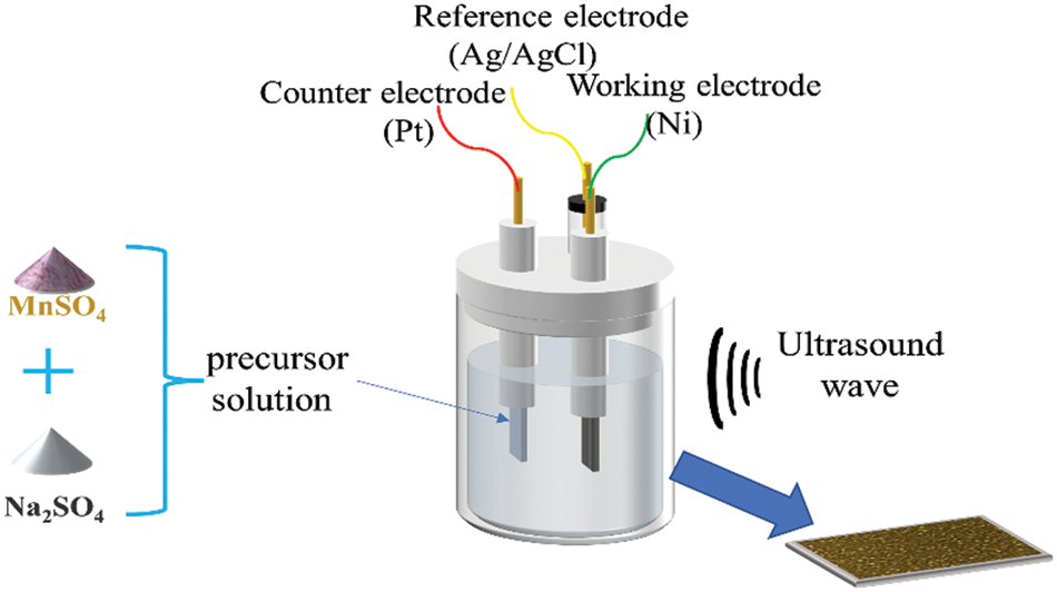
Figure 1: Schematic diagram of ultrasonic-assisted electrodeposition of MnO2
Scanning electron microscope (SEM, Zeiss ULTRA 55 SEM) and transmission electron microscope (TEM, FEI Tecnai G2 F20) were used to observe the microscopic morphology of the prepared MnO2 films.
2.3 Electrochemical Performance Measurement
Chronoamperometry (CA), cyclic voltammetry (CV), galvanostatic charge/discharge (GCD), and electrochemical impedance spectroscopy (EIS) were used to evaluate the electrochemical performance of the MnO2 thin film electrode in a three-electrode system (Each MnO2 electrode served as the working electrode, saturated Ag/AgCl served as the reference electrode, and Pt served as the counter electrode in the French BioLogic electrochemical workstation) at room temperature, using 1 M Na2SO4 solution as the electrolyte. According to the galvanostatic charge/discharge curve and cyclic voltammetry curve, obtained from the test, the following Eqs. (1) and (2) were used to compute the materials’ mass specific capacitance
In Eq. (1),
In Eq. (2), s represents the area of the MnO2 electrode sheet,
The Faradaic redox reactions of sodium ions embedded and de-embedded on the surface of MnO2 during the charging and discharging process are shown in Eq. (3) below.
Scanning electron microscopy (SEM) pictures of electrodes generated at various scan rates are shown in Fig. 2. Firstly, it can be observed that the manganese dioxide films showed a loose porous structure at lower scan rates. This might be because the water in the solution was electrolyzed to produce H2 and O2 at a high voltage (close to 1 V), and the Mn2+ near the bubbles could not reach the holes produced by the electrode oxidation to MnO2. In fact, it was observed that bubbles were generated in the electrolytic bath during the electrode deposition preparation. Secondly, the decrease in pores with increased scan rate was due to the fact that the electrode was kept for a longer time at high voltages with lower scan rates, while more bubbles were generated by the electrolysis of water in the solution. Besides, cracks on the film surface gradually increased with increasing scan rates due to uneven growth caused by the shorter growth time of the manganese dioxide nanomaterials at higher scan rates.
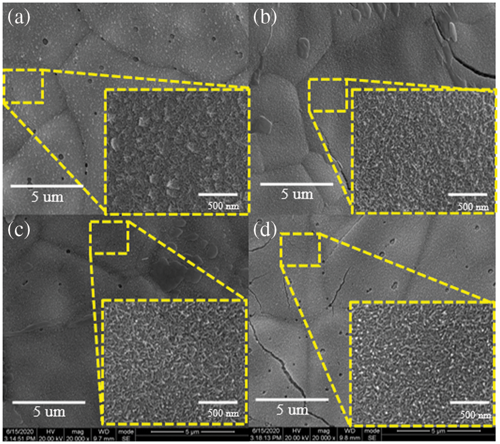
Figure 2: SEM images of electrodes at different scan rates (a) 40 mV/s, (b) 60 mV/s, (c) 80 mV/s, (d) 100 mV/s
In electron microscopy images at high magnification, the electrode samples at high scan rates showed a densely packed nanorod morphology with overlapping associations. This structure facilitated the rapid transfer and transport of electrons and ions, resulting in an increase in the number of active sites for electrochemical reactions and an increase in the materials’ specific capacitance. Additionally, at a scan rate of 40 mV/s, the aggregation of nanorods on the MnO2 electrode surface resulted in the formation of nanospheres which was because the longer electrode deposition time at low scan rates could lead to the growth of nanorods for a long time in a preferred orientation. However, the electrochemical redox reaction occurred mainly at the electrode surface. The active materials at the bottom of this structure were covered and cannot participate in the electrode reaction for capacitance provision. Thus, the material mass utilization was low.
To further understand the microstructure of the microstructure of the manganese dioxide electrode samples prepared, the prepared, the prepared samples were observed by using transmission electron microscopy (the selected samples were made at a scan rate of 80 mV/s for observation), as shown in Fig. 3. It can be observed from TEM Figs. 3a–3c that the manganese dioxide is presented as a densely packed nanorod morphology with overlapping associations. This non-dense three-dimensional structure has a high surface area ratio, which improves ion output from the electrolyte and the kinetics of manganese dioxide electrode reactions [33]. Fig. 3d shows the HR-TEM image of the electrode, where the lattice stripes are clearly visible with an interplanar crystal spacing of 0.24 and 0.21 nm, respectively, corresponding to the crystal faces (210) and (211) [34,35], respectively, which belong to the orthogonal crystal system.
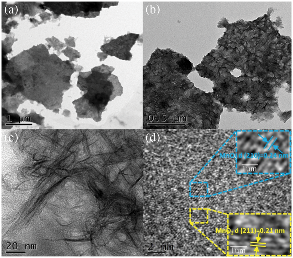
Figure 3: (a) (b) (c) TEM images of MnO2-sv80 at different magnifications, (d) HR-TEM image of MnO2-sv80
To conduct additional research on the sample surface’s oxidation state and chemical makeup, we characterized the MnO2-sv80 through the XPS technique. The results are shown in Fig. 4. Fig. 4a shows the Mn2p energy level diagram of the MnO2-sv80. The two peaks with spin splitting energy difference of 12.8 eV in the diagram are typical MnO2 characteristic peaks, corresponding to the 2p1/2 (641.7 eV) and the 2p3/2 (653.9 eV) of the MnO2, respectively [36]. Fig. 4b presents the O1s energy level diagram of the MnO2-sv80, with a center peak at 529.8 eV, corresponding to the Mn-O-Mn bond; the peak at 531.4 eV corresponds to the C=O bond, which may be due to CO2 in the air.

Figure 4: (a) Mn2p XPS spectra of MnO2-sv80, (b) O1s XPS spectra of MnO2-sv80
3.3 Electrochemical Properties
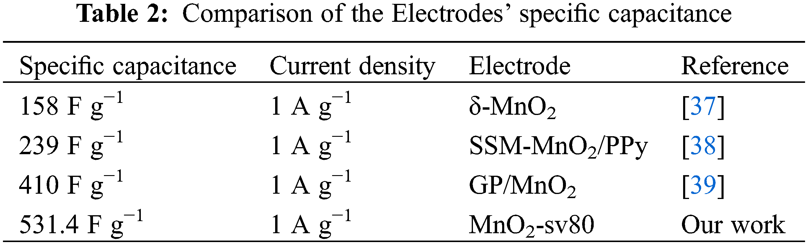
Fig. 5a shows each electrode sample’s constant current charge/discharge curves a with varying current densities (1 A g−1, 2 A g−1, 5 A g−1, 10 A g−1, 20 A g−1). To begin, it is discovered that each electrode’s charge/discharge curves resemble equilateral triangles, which indicates good electrode reversibility. Secondly, there is a voltage drop when each electrode is discharged. The reason for the IR drop is the self-induction electromotive force, which is generated during the conversion process from charging to discharging between the equivalent series resistance of the electrodes and inductive coupling. Additionally, MnO2-sv80 has a significantly longer discharge time than the other electrodes, indicating the highest specific capacitance. The specific capacitance of each electrode with varying current densities can be computed using GCD curves and Eq. (1), as shown in Fig. 5b. The MnO2-sv80 electrode has an overlapping-associated nanorod structure characterized by a large specific surface area, which can provide more Na+ embedding/de-embedding sites. As a result, the MnO2-sv80 electrode obtained an ultra-high specific capacitance of 531.4 F g−1, and it also had a high specific capacitance of 223.2 F g−1 and a capacitance retention of 42% at a current density of 20 A g−1. However, at a current density of 1 A g−1, the specific capacitance of the MnO2-sv40 electrode samples was only 220 F g−1, which was because MnO2 had a longer deposition time at low scan rates, resulting in an increase in film thickness, and even the selective growth of MnO2 nanosphere structure on the surface of this electrode. However, the electrode reaction occurred mainly on the surface of the electrode sheet. The covered MnO2 inside could not participate in the electrode reaction and then could not provide specific capacitance, which led to extremely low utilization of material mass. Moreover, all samples’ specific capacitance falls as the current density increases, owing to the active materials’ inability to complete their reaction at high current densities. We obtained the non-toxic and non-polluting MnO2 electrode material was prepared using a simple linear sweep voltammetry procedure by electrodeposition on a three-dimensional porous nickel foam substrate. Then, the higher specific capacitance was obtained without extra doping or a secondary processing process (see Table 2 for a comparison with previous research).

Figure 5: (a) GCD curves of each sample at 1 A g−1, (b) The specific capacitance (F g−1) at different current densities of each sample, (c) CV curves of each sample, (d) The specific capacitance (mF cm−2) of each sample, (e) The image of the current time obtained using the timing current method, (f) Capacitance retention of each electrode at a current density of 2 A g−1
Additionally, cyclic voltammetry is a critical technique for determining the electrochemical properties of materials. Fig. 5c shows at the scan rate of 5 mV/s, the cyclic voltammetry curves of those samples were prepared at different scan rates. It can be seen that all samples have a pair of obvious redox peaks around 0.7–0.9 V. The cyclic voltammetry curve of MnO2-sv80 is approximately rectangular curve shape and has good symmetry plus, the ratio of the absolute values of the oxidation and reduction peaks is closer to 1. This indicates that this electrode material’s charging and discharging process is dynamic and reversible. Moreover, the CV curve of the sample with an 80 mV/s scan rate has the largest area, indicating that the sample has a higher area specific capacitance. As illustrated in Fig. 5d, the area specific capacitance of each electrode sample can be calculated using the CV curve and Eq. (2). At first, as the scan rate increased, the active material deposition became smaller, and the thin film electrode thickness became thinner. Thus, the MnO2 nanomaterial could fully contact and react with the electrolyte, which improved the utilization of the active material mass. Then, as the scan rate further increased, the electrode specific capacitance decreased due to the low MnO2 deposition despite the high mass utilization rate. Thus, as the scan rate increased, the electrode area specific capacitance increased first and then decreased due to the synergistic effect of these two factors. However, the mass of active material increases as the specific capacitance decreases. This is due to inadequate reaction and low utilization, mainly caused by surface intercalation or electric double-layer adsorption.
Chronoamperometry is an important technique used to study the electrode reaction process and the stability of electrode materials. Fig. 5e shows the CA curves of each MnO2 electrode sample. As can be seen from the figure, the electric currents of all samples are rapidly decreasing. The electrode reaction process is mainly influenced by diffusion at the same time, thereafter, the decline is gradually slowed down until it stabilizes. Among them, the sample with a scan rate of 80 mV/s has a relatively flat decline and a high current density, which indicates its relatively sensitive electrochemical response and relatively stable electrochemical performance. This is attributed to the relatively stable interlacing-associated nanorod structure of the MnO2-sv80 sample.
Fig. 5f shows the long-term cycling performance of each electrode. The cyclic charge/discharge characteristics were obtained through 5000 times charging and discharging in the 1 mol·L−1 Na2SO4 electrolyte at a current density of 2 A g−1. It can be observed that the specific capacitance of each electrode at the preliminary stage gradually decreases as the charging frequency increases. This is owing to the cyclic charging and discharging process, in which sodium ions are adsorbed on the surface and embedded into MnO2 through ion channels, forming MnOONa and transforming manganese from tetravalent to trivalent. Thus, further embedding will form divalent MnOONa2. Thus, further embedding will form divalent MnOONa2, leading to the collapse of the manganese dioxide material structure. Also, Mn2+ dissolving in the electrolyte results in an irreversible capacity decay. In fact, we observed that the sodium sulfate solution turned brown during the testing phase. Additionally, the MnO2-sv80 electrode exhibits the highest cycle retention rate, up to 85.4 percent, which is attributed to its interlaced nanorod structure with a high specific surface area, which results in increased stability while minimizing the effect of electrode volume expansion during the cyclic charging and discharging process, thereby increasing the electrode’s cycle retention rate.
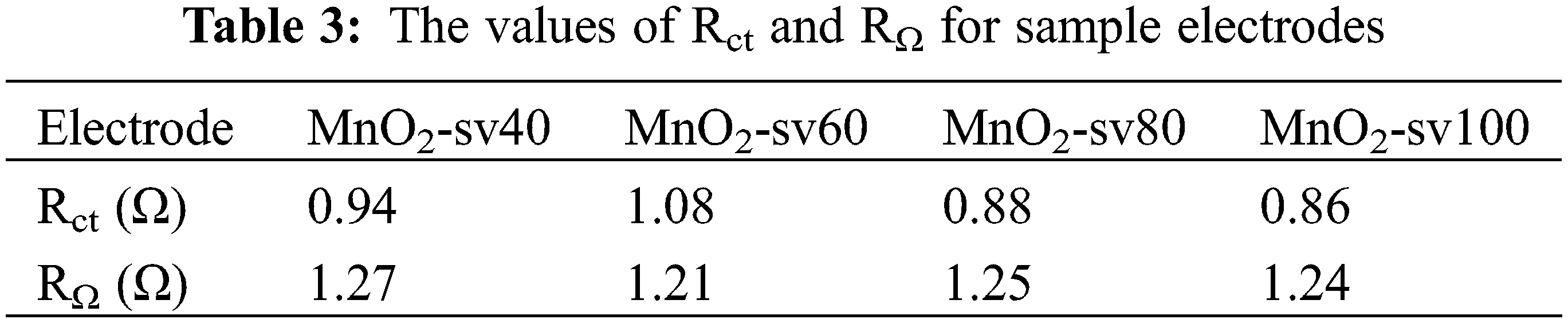
To further investigate the electrode materials’ electrochemical characteristics, we employed electrochemical impedance spectroscopy (EIS) to determine their charge transfer kinetics and chemical process. The electrode’s electrochemical reaction process is depicted in Fig. 6a, and it may be classed as either Faradaic or double-layer capacitive. Additionally, the faradaic process generates charge transfer resistance (Rct) and Warburg impedance (Zw). Into a result, the reaction process may be abstracted as comparable circuits, as seen in Fig. 6b, where RΩ represents the resistance between the electrode material and electrolyte, Cd represents double-layer capacitance, Zf represents the Faradaic impedance produced for the redox reactions and Zf = Rct + Zw. Fig. 6b shows the frequency variation curve of the electrical impedance modulus of the electrode. Electrical impedance is less than ten ohms in the high-frequency range and up to in the low-frequency region, which is characteristic of capacitive behavior. The magnified views in Figs. 6c and 6d show the Nyquist plot of each MnO2 thin film electrode with its high-frequency area. At the high-frequency intercept on the real axis, the equivalent series resistance (ESR) is composed of the ionic resistance of the electrolyte, the contact resistance between the electrolyte and the electrode, and the resistance of the active material [40]. When the Warburg impedance is between the middle and high-frequency ranges, the plot of the impedance spectroscopy is a semicircle, and the intercept between the semicircle and the real axis is RΩ, which can be analyzed in combination with the equivalent circuit. The low impedance module on the curve corresponds to the high-frequency region. The changing cycle in the high-frequency region is so short that the material transfer does not occur in time. Hence, the role of Zw in the equivalent circuit can be ignored. And in the high-frequency region, capacitor Cd shortens the circuit between Rct and Zw. Thus, the impedance is only RΩ. This situation corresponds to the intersection of this curve on the X-axis, As a result, the intercept size of the curve on the X-axis is equal to RΩ. Additionally, the diameter of the circle represents the charge transfer resistance (Rct) [41]. At low frequencies, the time of substance transfer is adequate, thus being dominant. The Warburg (Zw) impedance increases with decreasing frequency, and the curve depicts a straight line with a slope near one. The smaller Warburg (Zw) impedance of MnO2-sv80 accelerates the ionic diffusion in the active materials and electrolytes, as well as the transfer of electrons and ions, having a positive impact on the reaction of the Faradaic processes, which can provide a larger specific capacitance [42]. Table 3 below shows values of Rct and RΩ which are determined by fitting the curves and the corresponding circuit. The smaller Rct and RΩ of MnO2-sv80 with the smaller loaded fraction of active substance is due to the poor electronic conductivity of MnO2, and the thinner electrode thickness and larger electrode surface area further reduce the electrode impedance.

Figure 6: (a) The electrochemical reaction at the electrode, (b) Fitting circuit and Variation of impedance modulus with frequency, (c), (d) Nyquist plot of each MnO2 film electrode
In conclusion, in the preparation of the MnO2 thin-film electrode, the electrochemical deposition method could help better control the thickness of the film, avoiding needless waste of materials while improving the energy storage efficiency. Meanwhile, the entire electrodeposition process did not require sintering of the material, which avoided unnecessary energy consumption and was therefore environmentally friendly. We prepared MnO2 thin-film electrodes through modified ultrasound-assisted sweep voltammetry and four sets of samples were obtained by scan rate control to regulate the electrodeposition process. These measurements were employed to investigate the mechanism by which the scanning rate affects the growth of MnO2. Scanning electron microscopy (SEM) and transmission electron microscopy (TEM) were used to observe each sample’s surface morphology and microscopic morphology. The electrochemical characteristics of the produced samples were then determined using chronoamperometry (CA), cyclic voltammetry (CV), galvanostatic charge/discharge (GCD), and electrochemical impedance spectroscopy (EIS). The result suggests that the MnO2-sv80 electrode sample at a scan rate of 80 mV/s has excellent performance for the supercapacitor electrode. The specific capacitance was as high as 531.4 F g−1 at a current density of 1 A g−1, and remained at 223.2 F g−1 at an ultra-high current density of 20 A g−1, with capacitance retention of 42%.
Data Availability Statement: The data supporting this study’s findings are accessible upon reasonable request from the corresponding author.
Funding Statement: The current work was sponsored by the National Natural Science Foundation of China (NSFC) Nos. 11675029 and 51708015 and supported by Sichuan Science and Technology Program (2021JDRC0020, 2022JDRC0080).
Conflicts of Interest: There are no other relationships or activities that could appear to have influenced the submitted work, and no conflict of interest exists in the submission of this manuscript.
References
1. Dubal, D. P., Ayyad, O., Ruiz, V., Gómez-Romero, P. (2015). Hybrid energy storage: The merging of battery and supercapacitor chemistries. Chemical Society Reviews, 44(7), 1777–1790. DOI 10.1039/C4CS00266K. [Google Scholar] [CrossRef]
2. Simon, P., Gogotsi, Y. (2008). Materials for electrochemical capacitors. Nature Materials, 7(11), 845–854. DOI 10.1038/nmat2297. [Google Scholar] [CrossRef]
3. Jiang, J., Li, Y., Liu, J., Huang, X., Yuan, C. et al. (2012). Recent advances in metal oxide-based electrode architecture design for electrochemical energy storage. Advanced Materials, 24(38), 5166–5180. DOI 10.1002/adma.201202146. [Google Scholar] [CrossRef]
4. Yuan, C., Wu, H. B., Xie, Y., Lou, X. W. (2014). Mixed transition-metal oxides: Design, synthesis, and energy-related applications. Angewandte Chemie International Edition, 53(6), 1488–1504. DOI 10.1002/anie.201303971. [Google Scholar] [CrossRef]
5. Cheng, Z., Deng, Y., Hu, W., Qiao, J., Zhang, J. (2015). A review of electrolyte materials and compositions for electrochemical supercapacitors. Chemical Society Reviews, 44(21), 7484–7539. DOI 10.1039/C5CS00303B. [Google Scholar] [CrossRef]
6. Yu, J., Fu, N., Zhao, J., Liu, R., Li, F. et al. (2019). High specific capacitance electrode material for supercapacitors based on resin-derived nitrogen-doped porous carbons. ACS Omega, 4(14), 15904–15911. DOI 10.1021/acsomega.9b01916. [Google Scholar] [CrossRef]
7. Cheng, H. H., Zhou, X. P., Gao, A. M., Yi, F. Y., Shu, D. et al. (2018). Supermolecule polymerization derived porous nitrogen-doped reduced graphene oxide as a high-performance electrode material for supercapacitors. Electrochimica Acta, 292, 20–30. DOI 10.1016/j.electacta.2018.09.092. [Google Scholar] [CrossRef]
8. Wang, G., Zhang, L., Zhang, J. (2012). A review of electrode materials for electrochemical supercapacitors. Chemical Society Reviews, 41(2), 797–828. DOI 10.1039/C1CS15060J. [Google Scholar] [CrossRef]
9. Zhang, Y., Mei, H., Cao, Y. (2021). Recent advances and challenges of electrode materials for flexible supercapacitors. Coordination Chemistry Reviews, 438, 213910. DOI 10.1016/j.ccr.2021.213910. [Google Scholar] [CrossRef]
10. Zhang, Y., Mei, H., Yang, J. (2020). New NiMoO4/CoMoO4 composite electrodes for enhanced performance supercapacitors. Ionics, 26(33), 3579–3590. DOI 10.1007/s11581-020-03470-3. [Google Scholar] [CrossRef]
11. Zhang, Y., Gao, H., Jia, X. (2018). NiMoO4 nanorods supported on nickel foam for high-performance supercapacitor electrode materials. Journal of Renewable and Sustainable Energy, 10(5), 054101. DOI 10.1063/1.5032271. [Google Scholar] [CrossRef]
12. Zhang, Y., Chang, C., Jia, X. (2020). Influence of metallic oxide on the morphology and enhanced supercapacitive performance of NiMoO4 electrode material. Inorganic Chemistry Communications, 112, 107697. DOI 10.1016/j.inoche.2019.107697. [Google Scholar] [CrossRef]
13. Zhang, Y., Chang, C., Jia, X. (2020). Morphology-dependent NiMoO4/carbon composites for high performance supercapacitors. Inorganic Chemistry Communications, 111, 107631. DOI 10.1016/j.inoche.2019.107631. [Google Scholar] [CrossRef]
14. Li, Y. J., Wang, G. L., Wei, T., Fan, Z. J., Yan, P. (2016). Nitrogen and sulfur co-doped porous carbon nanosheets derived from willow catkin for supercapacitors. Nano Energy, 19, 165–175. DOI 10.1016/j.nanoen.2015.10.038. [Google Scholar] [CrossRef]
15. Anwar, A. W., Majeed, A., Iqbal, N., Ullah, W., Shuaib, A. et al. (2015). Specific capacitance and cyclic stability of graphene based metal/metal oxide nanocomposites: A review. Journal of Materials Science and Technology, 31, 699–707. DOI 10.1016/j.jmst.2014.12.012. [Google Scholar] [CrossRef]
16. Cheng, Y., Liu, J. (2013). Carbon nanomaterials for flexible energy storage. Materials Research Letters, 1, 175–192. DOI 10.1080/21663831.2013.808712. [Google Scholar] [CrossRef]
17. Wang, W., Liu, W., Zeng, Y., Han, Y., Yu, M. et al. (2015). A novel exfoliation strategy to significantly boost the energy storage capability of commercialcarbon cloth. Advanced Materials, 27, 3572–3578. DOI 10.1002/adma.201500707. [Google Scholar] [CrossRef]
18. Zhai, T., Xie, S., Yu, M., Fang, P., Liang, C. et al. (2014). Oxygen vacancies enhancing capacitive properties of MnO2 nanorods for wearable asymmetric supercapacitors. Nano Energy, 8, 255–263. DOI 10.1016/j.nanoen.2014.06.013. [Google Scholar] [CrossRef]
19. Yang, P., Xiao, X., Li, Y., Ding, Y., Qiang, P. et al. (2013). Hydrogenated ZnO core-shell nanocables for flexible supercapacitors and self-powered systems. ACS Nano, 7, 2617–2626. DOI 10.1021/nn306044d. [Google Scholar] [CrossRef]
20. Zhang, Z., Chi, K., Xiao, F., Wang, S. (2015). Advanced solid-state asymmetric supercapacitors based on 3D graphene/MnO2 and graphene/polypyrrole hybrid architectures. Journal of Materials Chemistry A, 3(24), 12828–12835. DOI 10.1039/C5TA02685G. [Google Scholar] [CrossRef]
21. Abdur, R., Kim, K., Kim, J. H., Lee, J. (2015). Electrochemical behavior of manganese oxides on flexible substrates for thin film supercapacitors. Electrochimica Acta, 153, 184–189. DOI 10.1016/j.electacta.2014.11.187. [Google Scholar] [CrossRef]
22. Su, Z., Yang, C., Xu, C. (2013). Co-electro-deposition of the MnO2–PEDOT: PSS nanostructured composite for high areal mass, flexible asymmetric supercapacitor devices. Journal of Materials Chemistry A, 1, 12432–12440. DOI 10.1039/C3TA13148C. [Google Scholar] [CrossRef]
23. Gu, T., Wei, B. (2015). Fast and stable redox reactions of MnO2/CNT hybrid electrodes for dynamically stretchable pseudocapacitors. Nanoscale, 7(27), 11626–11632. DOI 10.1039/C5NR02310F. [Google Scholar] [CrossRef]
24. Yang, C., Shi, Y., Liu, N., Tao, J., Wang, S. et al. (2015). Freestanding and flexible graphene wrapped MnO2/MoO3 nanoparticle based asymmetric supercapacitors for high energy density and output voltage. RSC Advances, 2015(5), 45129–45135. DOI 10.1039/C5RA06152K. [Google Scholar] [CrossRef]
25. Yang, C., Shi, Y., Liu, N., Tao, J., Wang, S. et al. (2014). Flexible planar/fiber-architectured supercapacitors for wearable energy storage. Journal of Materials Chemistry C, 2, 1184–1200. DOI 10.1039/C3TC31706D. [Google Scholar] [CrossRef]
26. González, A., Goikolea, E., Barrena, J. A., Mysyk, R. (2016). Review on supercapacitors: Technologies and materials. Renewable and Sustainable Energy Reviews, 58, 1189–1206. DOI 10.1016/j.rser.2015.12.249. [Google Scholar] [CrossRef]
27. Zhang, Q. Z., Zhang, D., Miao, Z. C., Zhang, X. L., Chou, S. L. (2018). Research progress in MnO2-carbon based supercapacitor electrode materials. Small, 14, 1702883. DOI 10.1002/smll.201702883. [Google Scholar] [CrossRef]
28. Wang, H., Xu, C., Chen, Y., Yong, W. (2017). MnO2 nanograsses on porous carbon cloth for flexible solid-state asymmetric supercapacitors with high energy density. Energy Storage Materials, 8, 127–133. DOI 10.1016/J.ENSM.2017.05.007. [Google Scholar] [CrossRef]
29. Bao, L. H., Zang, J. F., Li, X. D. (2011). Flexible Zn2SnO4/MnO2 Core/Shell nanocable-carbon microfiber hybrid composites for high-performance supercapacitor electrodes. Nano Letters, 11, 1215–1220. DOI 10.1021/nl104205s. [Google Scholar] [CrossRef]
30. Guillemet, P., Brousse, T., Crosnier, O., Dandeville, Y., Athouel, L. et al. (2012). Modeling pseudo capacitance of manganese dioxide. Electrochimica Acta, 2012(67), 41–49. DOI 10.1016/j.electacta.2012.01.110. [Google Scholar] [CrossRef]
31. Toupin, M., Brousse, T., Belanger, D. (2014). Charge storage mechanism of MnO2 electrode used in aqueous electrochemical capacitor. Chemistry of Materials, 16(16), 3184–3190. DOI 10.1021/cm049649j. [Google Scholar] [CrossRef]
32. Zhang, M., Yang, D. Y., Li, J. T. (2021). Ultrasonic and NH4+ assisted Ni foam substrate oxidation to achieve high performance MnO2 supercapacitor. Applied Surface Science, 541, 148546. DOI 10.1016/j.apsusc.2020.148546. [Google Scholar] [CrossRef]
33. Wang, J. G., Kang, F., Wei, B. (2015). Engineering of MnO2-based nanocomposites for high-performance supercapacitors. Progress in Materials Science, 74, 51–124. DOI 10.1016/j.pmatsci.2015.04.003. [Google Scholar] [CrossRef]
34. Xu, M., Kong, L., Zhou, W. (2007). Hydrothermal synthesis and pseudocapacitance properties of alpha-MnO2 hollow spheres and hollow urchins. Journal of Physical Chemistry C, 112(51), 19141–19147. DOI 10.1021/jp076730b. [Google Scholar] [CrossRef]
35. Wang, K. P., Teng, H. (2007). Structural feature and double-layer capacitive performance of porous carbon powder derived from polyacrylonitrile-based carbon fiber. Journal of the Electrochemical Society, 154(11), A993–A998. DOI 10.1149/1.2775284. [Google Scholar] [CrossRef]
36. Nesbitt, H. W., Banerjee, D. (1998). Interpretation of XPS Mn(2p) spectra of Mn oxyhydroxides and constraints on the mechanism of MnO2 precipitation. American Mineralogist, 83(3–4), 305–315. DOI 10.2138/am-1998-3-414. [Google Scholar] [CrossRef]
37. de Oliveira Cremonezzi, J. M., Tiba, D. Y., Domingues, S. H. (2020). Fast synthesis of δ-MnO2 for a high-performance supercapacitor electrode. SN Applied Sciences, 2(10), 1689. DOI 10.1007/s42452-020-03488-2. [Google Scholar] [CrossRef]
38. Liu, G., Liu, J., Xu, K., Wang, L., Xiong, S. (2021). Fabrication of flexible graphene paper/MnO2 composite supercapacitor electrode through electrodeposition of MnO2 Nanoparticles on graphene paper. ChemistrySelect, 6(26), 6803–6810. DOI 10.1002/slct.202101207. [Google Scholar] [CrossRef]
39. He, D., Zhang, L., Peng, X., Wan, J., Zhao, C. (2020). Preparation of stainless steel mesh-supported MnO2/polypyrrole nanocomposites as binder-free electrode for supercapacitor. Nano Brief Reports and Reviews, 15(3), 2050031. DOI 10.1142/S1793292020500319. [Google Scholar] [CrossRef]
40. Reddy, B. J., Vickraman, P., Justin, A. S. (2019). A facile synthesis of novel α-ZnMoO4 microspheres as electrode material for supercapacitor applications. Bulletin of Materials Science, 42(2), 1–6. DOI 10.1007/s12034-019-1749-9. [Google Scholar] [CrossRef]
41. Stoller, M. D., Park, S., Zhu, Y., An, J., Ruoff, R. S. (2008). Graphene-based ultracapacitors. Nano Letters, 8(10), 3498–3502. DOI 10.1021/nl802558y. [Google Scholar] [CrossRef]
42. Luo, J. Y., Jang, H. D., Huang, J. X. (2013). Effect of sheet morphology on the scalability of graphene-based ultracapacitors. ACS Nano, 7(2), 1464–1471. DOI 10.1021/nn3052378. [Google Scholar] [CrossRef]
 | This work is licensed under a Creative Commons Attribution 4.0 International License, which permits unrestricted use, distribution, and reproduction in any medium, provided the original work is properly cited. |