DOI:10.32604/jrm.2021.011596
| Journal of Renewable Materials DOI:10.32604/jrm.2021.011596 | |
| Article |
The Effects of Different Post-Heat Treatments on Rolling Contact Fatigue Behaviors of Direct Laser Cladding Inconel 625 Coatings
1School of Materials Science and Engineering, Wuhan University of Technology, Wuhan, 430070, China
2School of Mechanical and Electronic Engineering, Wuhan University of Technology, Wuhan, 430070, China
3School of Mechanical Engineering, Xi’an University of Science and Technology, Xi’an, 710054, China
4State Key Laboratory of Tribology, Tsinghua University, Beijing, 100084, China
5Shandong Key Laboratory of Corrosion Science, Institute of Oceanology, Chinese Academy of Sciences, Qingdao, 266071, China
*Corresponding Authors: Chen Zhou. Email: 397794895@qq.com; Xuewu Li. Email: lixuewu55@xust.edu.cn
Received: 18 May 2020; Accepted: 30 June 2020
Abstract: In this paper, the microstructures and rolling contact fatigue behaviors of laser cladding Inconel 625 coatings with or without post-heat treatments were analyzed. The results revealed that the fatigue resistance of the laser cladding coating after any post-heat treatment was worse than that of the as-deposited coating. First, through the finite element analysis, the distribution of stress along the thickness direction of the coating was obtained, and it was concluded that the bonding interface between the coating and the matrix had little effect on the fatigue properties of the coating. Then X-ray diffraction (XRD), scanning electron microscopy (SEM) and energy dispersive spectrometry (EDS) were used to analyze the microstructure and failure morphology. The results revealed that the subsurface failure morphology of the coatings showed a consistent correlation with rolling fatigue property after different heat treatments. The TCP phase and carbides have been shown in the laser cladding coating. The coating after stress relieved annealing exhibited chain-shaped granular carbides on the grain boundaries which could accelerate crack propagation. The aging heat treatment made small amounts of Laves phase dissolved in the coating, while the dispersed phase was precipitated which could result in the formation of pores. And the solution treatment made large amounts of Laves phase dissolved, while the rod-shape brittle phases were generated which was easy to fracture and contribute to crack initiation and spalling.
Keywords: Laser cladding; Inconel 625 coating; heat treatment; rolling contact fatigue; microstructure
 | This work is licensed under a Creative Commons Attribution 4.0 International License, which permits unrestricted use, distribution, and reproduction in any medium, provided the original work is properly cited. |
With the development of aerospace, chemical and other fields, the requirements for the service environment of mechanical parts are getting higher, resulting in higher surface property requirements for mechanical parts [1]. Due to rolling contact fatigue failure [2] and wear failure [3], many mechanical components such as wheels and cutting tools are vulnerable to premature failure. Laser cladding, as a widely used additive manufacturing (AM) technique [4], can deposit metal powder on the substrate and form a dense coating, thereby effectively improving the rolling contact fatigue resistance of the part surface [5].
The rolling contact fatigue failure modes of coatings are usually divided into four types: pitting, wear, crack and delamination. In recent years, domestic and foreign scholars have studied the theoretical mechanism of rolling contact fatigue behavior of the coatings. Xu et al. [2] studied the rolling contact fatigue behaviors and failure mechanisms of laser cladding WC/Ni composite coatings, and recorded the coating surface failure morphologies for different rolling cycles. Wang et al. [6–9] found that laser cladding iron-based and cobalt-based coatings significantly improved the wear resistance and fatigue spalling resistance of wheel and track rollers, and effectively prolonged the wear life of wheels and rails. It has been found that the surface status of the coating can have significant effects on the rolling contact fatigue behavior of the coating [10]. Appropriate surface roughness can fully improve the rolling contact fatigue life of the coating, while the polished surfaces have not significantly improved it [11]. The stronger bonding ability between the coating and the substrate, the more beneficial it can be to prolong the contact fatigue life of the coating [12]. The thickness of the coating affects the distribution of the shear stress in the coating [13,14], which can result in the variation of the fatigue failure modes. Too high or too low hardness will reduce the rolling contact fatigue life of the coating [15]. In addition, the failure mechanism of the coating is related to the microstructure of the coating and the orthogonal shear stress inside the coating [16]. The adjunction of suitable elements is beneficial to improving the rolling contact fatigue life of the coating [5,17,18]. Roy et al. [19] have studied the effects of deposition materials and heat treatment processes on the rolling contact fatigue damage behavior of laser cladding hypereutectoid steel rails, and reduced the hardness value of the coating to the target range.
In the laser repairing field, laser metal deposition Inconel 625 alloy has shown good wear resistance, high temperature resistance, and strong corrosion resistance [20], and is widely used in the aerospace and energy industries [21]. In general, non-equilibrium solidification during laser cladding will contribute to much residual stress and severe element segregation in the coating [22,23], and post-heat treatments of the coated parts are required to optimize the structure of the cladding layer to improve its mechanical properties. Considering that the heat treatment will result in the grain size change and phase transformation of the 1045 steel substrate and laser-deposited Inconel 625 [24,25], which will affect the mechanical properties, three universally applicable post-heat treatments schemes have been designed in this paper. This paper has studied the influence mechanism of different post-heat treatments on the rolling contact fatigue behaviors of laser cladding Inconel 625 coatings, and provides guidance for the engineering application of additive manufactured Inconel 625 materials under cyclic loading.
AISI 1045 steel with size 150 × 150 × 25 mm was selected as substrates. The Inconel 625 powders with an average particle diameter ranging from 50 to 108 μm were dried for 6 h at 60°C before cladding. The composition of Inconel 625 was shown in Tab. 1. Laser processing was carried out with the YSL-4000 fiber laser. The powder was pre-placed on the surface of the substrate, and then the surface was scanned by laser, while the schematic has been shown in Fig. 1. As the laser heat source moving, the cladding powder and the thin layer of the substrate surface melt at the same time and solidify quickly, while the surface coating forms with the strong metallurgical combination with the substrate. The process parameters were: laser power 2800 W, scanning speed 5 mm/s, overlap 5 mm, powder coating thickness 0.5 mm, and laser spot diameter 5 mm.
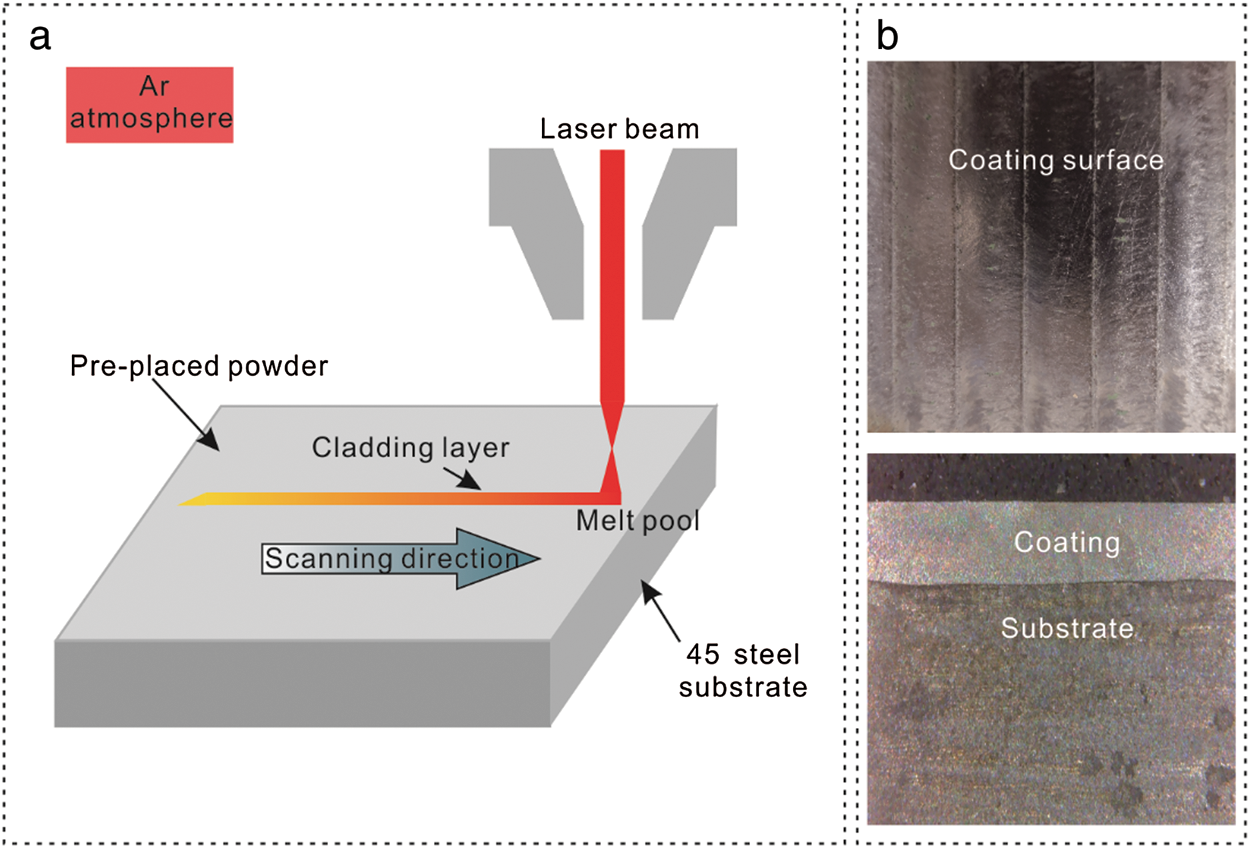
Figure 1: (a) Laser cladding process; (b) The macro morphology of the cladding layer
Table 1: The chemical composition content of Inconel 625 powder (wt%)

The specimens after cladding were cut by the wire electrical discharge machining to size 5 × 5 × 3 mm for the metallographic analysis of surface and subsurface, size 20 × 20 × 20 mm for the phase analysis and size 50 × 50 × 25 mm for the rolling contact test. The laser cladding Inconel 625 coatings were heat treated by stress relieved annealing, direct ageing and solution treatments as schematized in Tab. 2. Furthermore, all the heat-treated specimens were air cooling.
Table 2: Heat treatment scheme
2.3 Microstructure Characterization
XRD patterns (D/MAX-RB) were obtained using Cu Kα radiation over a 2θ range from 20° to 100°, with scanning speed of 1°/min. Metallographic specimens were polished and etched with the solution of 60 mL HCl and 20 mL HNO3, while the observation surfaces included coating surfaces and coating cross sections. JEM-7500F field emission scanning electron microscope (FSEM) with X-maxN80 energy dispersive spectrometer (EDS) detector was used to observe the microstructures of the coatings and perform energy spectrum analysis.
Firstly, the coating surface with four different heat treatments was polished, and HV-1000 micro-vickers hardness tester was used for hardness test, with a load of 0.1 kg for 10 s. 10 points were randomly selected on the whole polishing surface for measurement, and the average value was taken as the hardness of the specimen.
To keep the coating thickness and surface roughness consistent, the coatings of the block specimens were machined to the thickness of 400 μm before the rolling contact test. The rolling contact test was carried out with the device which is modified by the WWW-1 friction and wear testing machine as schematically shown in Fig. 2. During the test, the bearing ball roller driven by an electric motor was rotated in contact with the specimen (disc). With the total load of 2500 N, the speed of 1200 r/min, and the number of cycles of 1.2 × 10⁷, the rolling contact test was carried out for 1000 minutes without lubrication. The failure mode with the highest frequency of each specimen was taken as the failure mode.
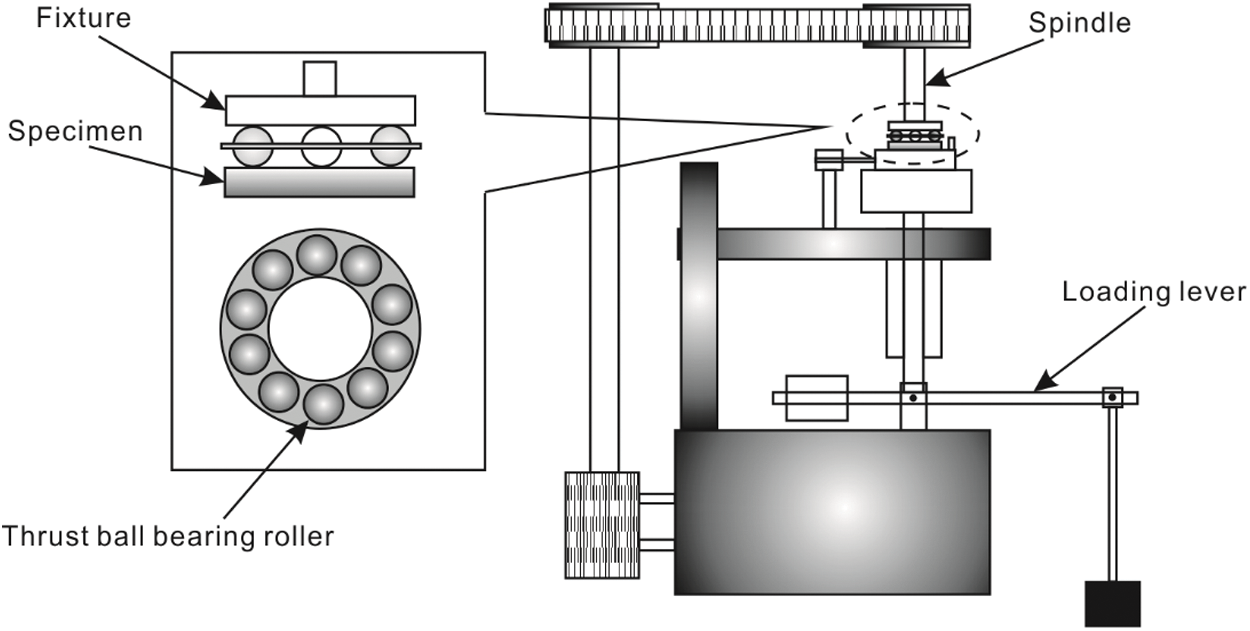
Figure 2: Schematic of roller-on-disc wear tester and the arrangement of the specimens
After the rolling contact test, the white light interference 3D topography instrument, which was the integrated module of American Rtec Instruments MFT-5000 modular friction and abrasion tester, was used to measure the wear tracks on the failure surface of the coatings. 8 points with wide wear tracks was measured for each specimen, and the point with the deepest wear track was chosen.
According to the Hertz contact theory, the finite element (FE) software ABAQUS was used to simulate and analyze the internal stress distribution of the coating. The spherical-surface contact model is an axisymmetric model, which is simplified and meshed, as shown in Fig. 3. The diameter of the ball in the model was set as 9.5 mm. To simplify the interface, the matrix and the coating were previously connected by grid joint. The penalty function was selected as the contact algorithm between the ball and the coating. The thickness of the coating is 400 μm, and the elastic modulus of the rolling ball (GCr15), the coating and the substrate are 219 GPa, 205 Gpa, and 206 Gpa, respectively, while the poisson’s ratios of them are 0.3, 0.308, and 0.3.
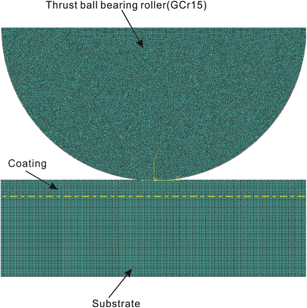
Figure 3: The spherical-surface contact model
The curve of the internal stress of the coating along the thickness direction was obtained as shown in Fig. 4. Both the normal stress and the shear stress are abruptly changed at the interface. It can be found that the depth corresponding to the maximum shear stress is 92 μm. The depth of the maximum shear stress is far from the interface between the substrate and the coating, which indicates that the influence of the interface can be ignored, therefore, the rolling contact fatigue failure will not occur from the interface [26].
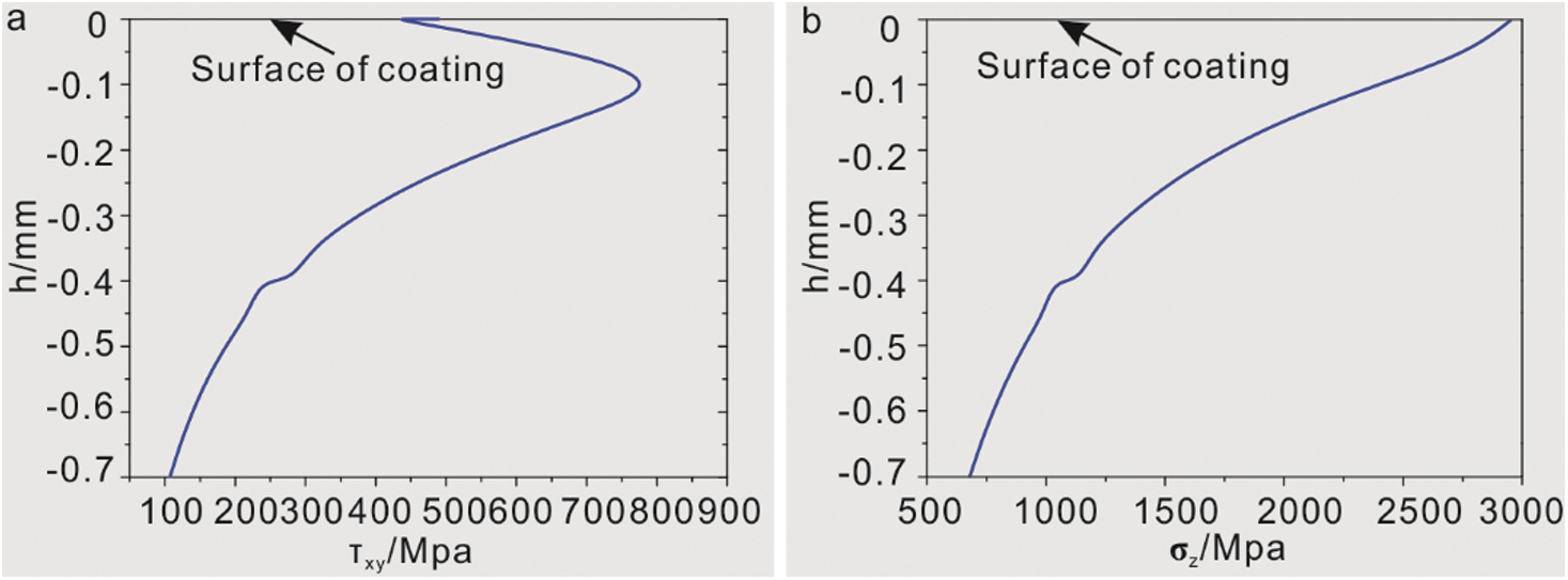
Figure 4: The (a) shear stress and (b) normal stress of the coating along the thickness direction
4.1 Rolling Contact Fatigue Property of Coatings
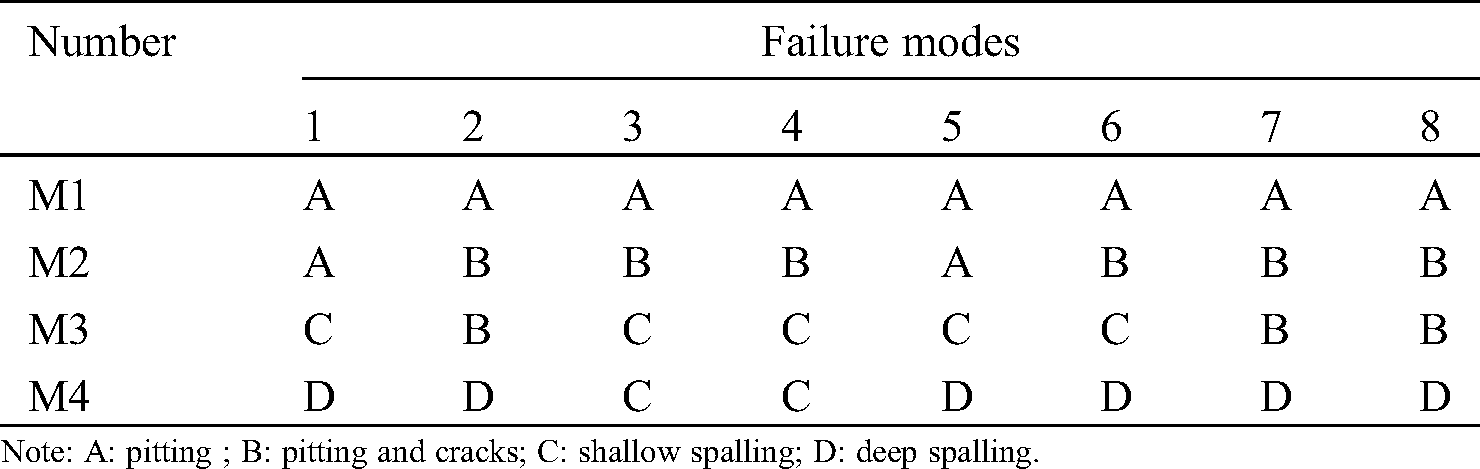
The contact fatigue failure modes of coatings with different heat treatment were shown in Fig. 5 and Tab. 3. The results showed that the rolling contact fatigue resistance of the Inconel 625 coating after the post-heat treatment was worse than that of the as-deposited coating, and the failure modes of coating under different heat treatment processes was also different. As shown in Fig. 5a, the failure mode of M1 was the typical pitting failure, and the pitting distribution was dense with irregular shapes. In Fig. 5b, M2 exhibited pitting with increased sizes compared to those in M1, and cracks with width of 5 μm and length of 100 μm. In Fig. 5c, the failure mode of M3 was mainly spalling. Under the effect of cyclic stress, spalling layers with width of about 5 μm and long length were formed. The depth of the spalling pitting was much smaller than the depth of the maximum shear stress. There were cracks at the boundary of the spalling layer, as the number of cycles increased, these cracks continued to expand. There were also pitting in the exfoliation layer, which could continue to develop and result in deeper spalling layers. In Fig. 5d, M4 has shown spalling failure. There were shallow spalling and deep spalling, while deep spalling was the further development of shallow spalling due to the increasing number of cycles. The failure modes of M1, M2, M3 and M4 were all different. Among them, the failure degree of M1 was the least, while the failure degree of M4 was the most serious.
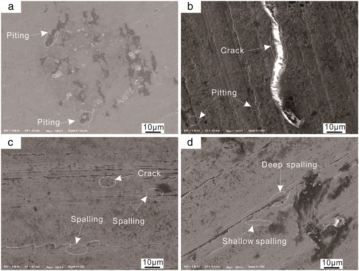
Figure 5: Coating surface contact fatigue failure modes of (a) M1, (b) M2, (c) M3 and (d) M4
Table 3: Failure modes of all specimen coatings with different heat treatment
It can be found from Fig. 6 that different heat treatments had significant effects on the hardness of the coating. The hardness values of M1, M2, M3, and M4 were 447 HV, 470 HV, 540 HV, and 417 HV, respectively. The results showed that stress relieved annealing and aging treatment increased the hardness of the coating, while solution treatment reduced the hardness of the coating. Fig. 7 showed the 2D profile of wear tracks. The relative difference between the maximum value and the minimum value of the vertical axis of the curve in Fig. 7 was taken as the depth of the wear tracks, which have been concluded in Tab. 4.
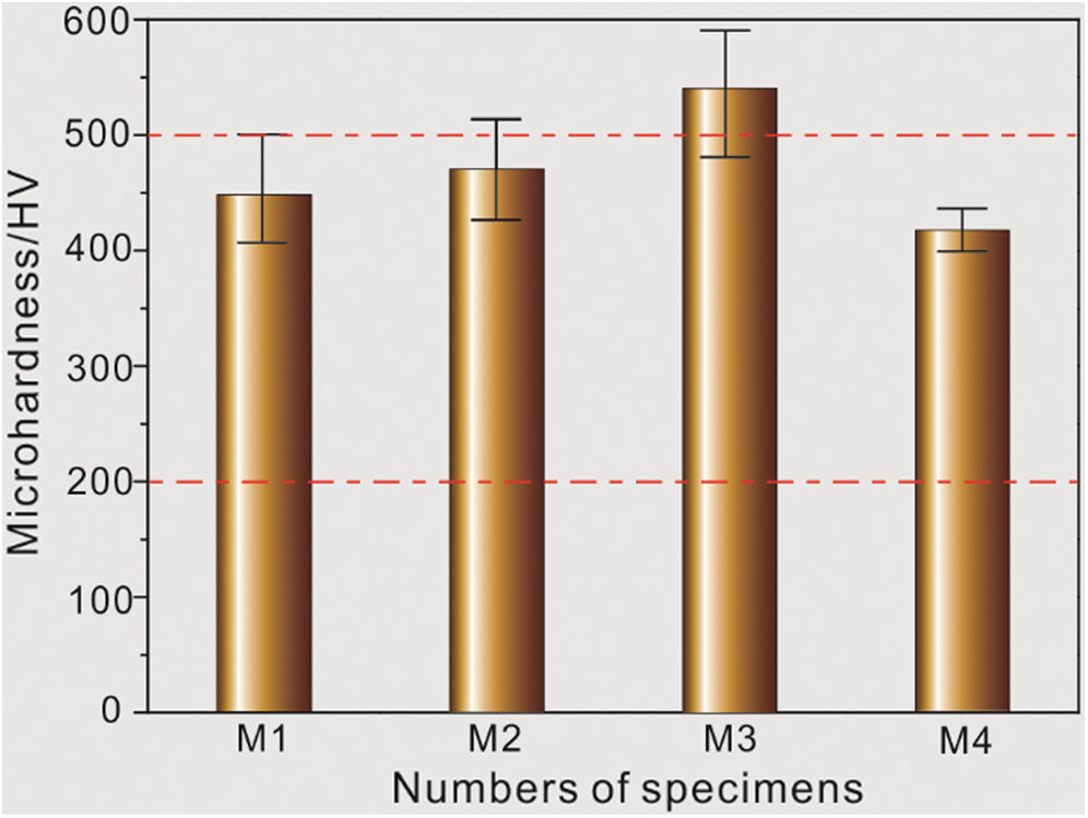
Figure 6: Hardness of coatings with different heat treatment
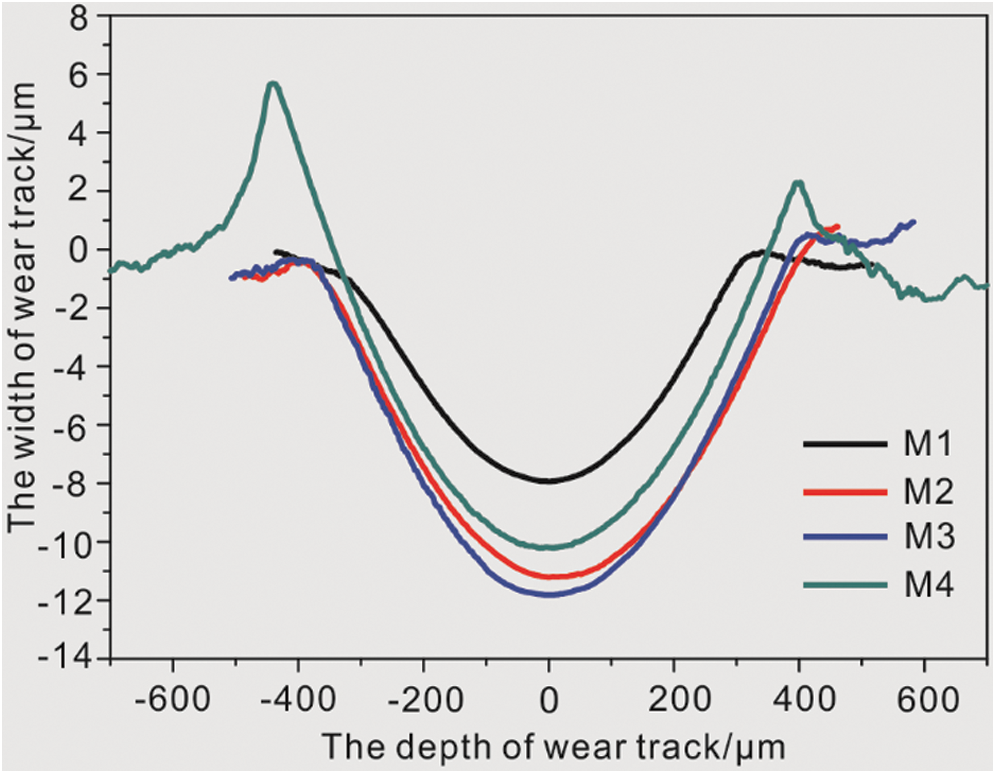
Figure 7: The wear tracks of coatings after different heat treatments
Table 4: Width and depth of failure wear track of different heat treatment coatings
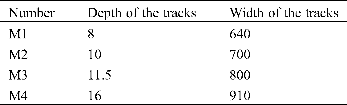
Under the cycle number of 1.2 × 10⁷, the wear track depth of M1 was 8 μm. After heat treatment, the width and depth of the failure wear tracks increased. Compared with M1, the wear track depth of M2 increased by 25%, the wear tracks depth of M3 increased by 15%, and M4 increased by 39% compared with M3. M4 showed obvious plastic deformation beside the wear tracks, and the width of the wear tracks was significantly wider than the other three specimens, which the reason was that the temperature of the heat treatment of M4 was in the medium temperature low plastic range of nickel-based alloy. M4 showed low yield strength, and the metal flow in the contact part gradually accumulated into the large plastic deformation under the effect of the steel ball in the contact fatigue test. In Fig. 7, the plastic deformation on the left side of the M4 wear track was larger than that on the right, because the inner side in rolling contact test was the left side which was more likely to accumulate into the large plastic deformation. Rolling contact fatigue was the fatigue failure in elastic deformation, M4 underwent plastic deformation under the same contact stress, which indicated that bearing capacity and contact fatigue performance of M4 was poor.
Fig. 8 showed the cross-section morphology of different heat-treated laser cladding coatings after the rolling contact tests. Figs. 8a, 8c, 8e, and 8g have exhibited the subsurface positions of M1, M2, M3, and M4, respectively. There were obvious influence zones in the four groups of coating sections, the width of which was about 10 μm, and the depth from the surface layer was about 80 μm, 76 μm, 83 μm, and 82 μm, respectively. Figs. 8b, 8d, 8f, and 8h referred to partial enlarged views of the red marked parts in the influence zones, and obvious cracks can be observed in the influence zones. According to the research of Miyashita [27], the maximum contact stress of contact fatigue occurs on the surface, and fatigue cracks are often located on the subsurface. According to the finite element analysis in Fig. 4a, it can be found that the depth of maximum shear stress was 92 μm. Both the location of the fatigue cracks initiation and the influence zones which has been shown in Fig. 8 correspond to the location of the maximum shear stress (subsurface). Therefore, the influence zones in Figs. 8a, 8c, 8e, and 8g was the subsurface. The initiation of cracks on the subsurface may be due to the damage accumulated to the maximum effective shear stress reaching the cracking strength. There were fewer cracks in M1, and the length of which were all less than 0.5 μm. M2, M3 and M4 had more cracks which were densely distributed. The damage accumulation resulted in the initiation of fatigue cracks during the rolling contact test. Under the same number of cycles, the crack density and crack sizes of M1 were small, indicating that M1 showed strong ability to resist fatigue crack initiation and better contact fatigue property than other specimens.
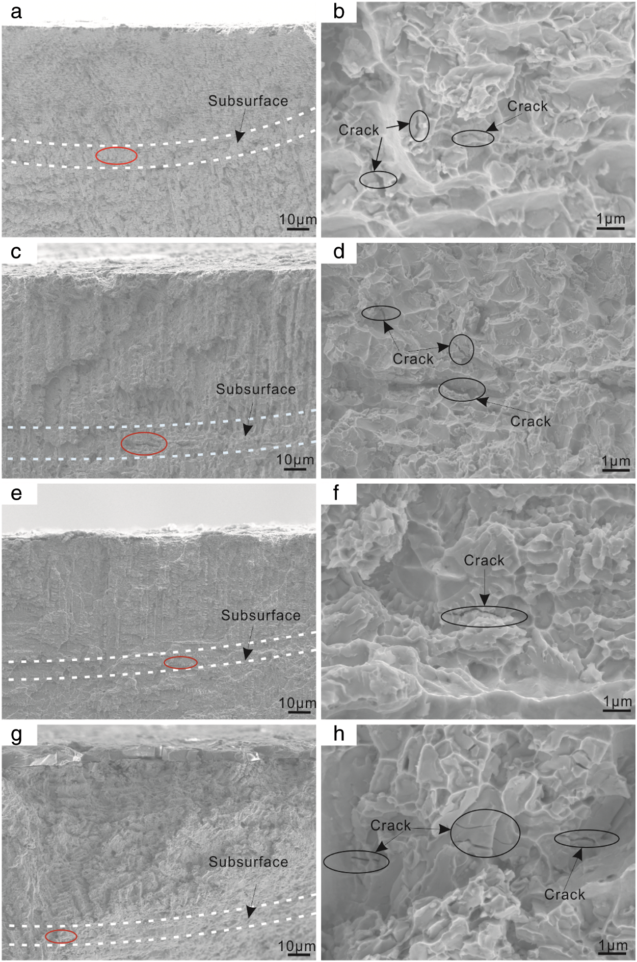
Figure 8: Morphology of cross section of coatings after the rolling contact test. (a), (c), (e), (g): The position of subsurface of M1, M2, M3, M4; (b), (d), (f), (h): Fatigue cracks of subsurface of M1, M2, M3, M4
The hardness of M2 and M3 coating was slightly higher than M1, which was generally beneficial for contact fatigue property [28]. However, the yield strength of M2 and M3 was lower than that of M1. Under the combined effect of strength and hardness, the failure degree of M2 and M3 appeared slightly more serious. In addition, M3 showed the much higher hardness than M1, which may result in the direct wear between the coating and contact parts, and cause the surface to peel off [15], therefore, the failure degree was more serious than M1. M4 showed the lowest hardness and the lowest yield strength which resulted in plastic deformation and significantly reduced its rolling contact fatigue property. Because of the effect of heat treatment on the strength and hardness of the laser cladding coating, under the same failure criterion, the status of the subsurface reaching the failure level differed, which was the main reason for the different surface failure morphology and cracks distribution.
4.2 Microstructure Characterization
The XRD analysis in Fig. 9 of the laser cladding Inconel 625 coatings with different post-heat treatments have revealed only the presence of single γ-Ni phase. No other phases were found in the XRD pattern, because many precipitated phases (such as γ” and δ phase) had much smaller size and lower content, which was hard to detect [20]. With the diffraction peak of (111) as shown in Fig. 9b, the lattice constant was calculated according to the Bragg formula 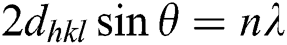 and the lattice constant calculation formula
  . λ is the wavelength of the X ray; θ is the angle of the diffraction peak; a is the lattice constant; h, k, l are the crystal planes of the diffraction peak.
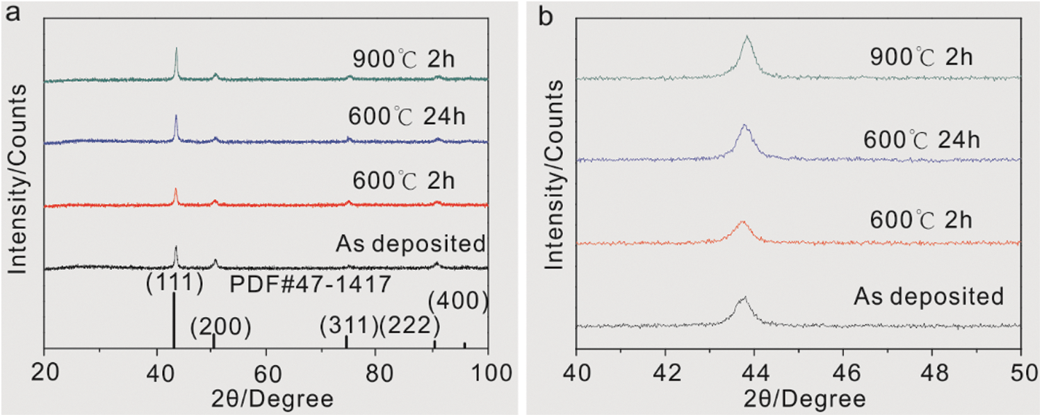
Figure 9: (a) XRD patterns of different heat-treated coatings; (b) (111) plane diffraction peak
As shown in Tab. 5, it can be found that the heat treatments have resulted in the decrease of lattice constant, indicating that different heat treatment processes resulted in solid solution elements (Nb, Mo) to precipitate from the matrix and generated new precipitated phases. The decrease of the lattice constant has led to the reduction of the yield strength of the γ-Ni matrix, which contributed to the different rolling contact failure modes.
Table 5: Lattice constants of coatings with different heat treatment
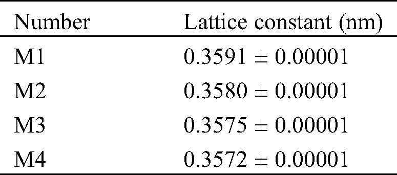
Fig. 10 revealed that the solidification structures of the four heat-treated specimens were composed of equiaxial dendrites and dendrites. Fig. 11 showed the element content at different points in Fig. 10. The main phase and precipitated phase need to be distinguished, while the pores can be observed around the precipitated phase of each specimen. There were obvious corrosion pits around the precipitated phase. EDS revealed that its Cr content was high, and the precipitate phase consumed large amounts of Cr around it, which has made the corrosion resistance of the surrounding area decrease. It was speculated to be M23C6 carbides, which could fall off to generate pits after etching.
Figure 10: Microstructure of different heat-treated coatings. (a) M1;(b) M2; (c) M3; (d) M4
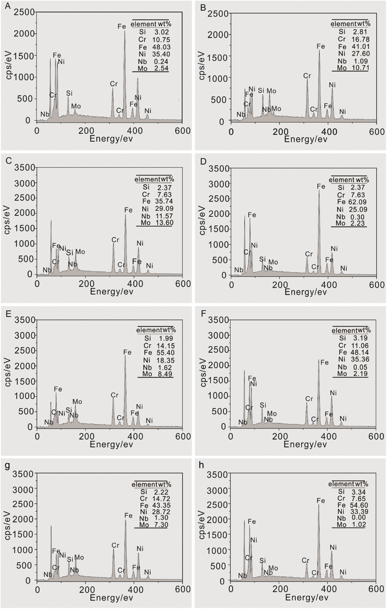
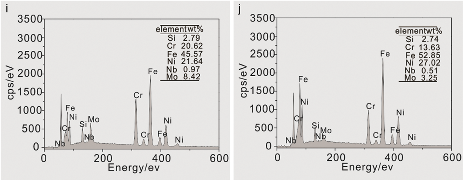
Figure 11: The element content of each point in Fig. 10 according to EDS analysis
In Fig. 10a, point A referred to γ-Ni matrix, and the content of Mo, Nb, and Cr in the net-shape precipitated phase at point B has significantly increased compared to the γ-Ni matrix. These net-shape precipitated phases were Topologically Close-Packed Phases (TCP) [29]. The formation of σ phase, μ phase, and P phase in the TCP all required the segregation of Nb, Mo, and Cr from the matrix. For the analysis of the irregular phase energy spectrum at point C, the percentage of the elements was approximately in accordance with A2B (A referred to Fe, Cr and Ni, B referred to Ni, Mo), which was speculated to be Laves phase [30]. Fig. 10b has shown the massive intergranular phase where chain-like carbides were present. The EDS analysis at point E revealed that the content of Cr and Mo in the bulk intergranular phase was lower than those in the net-shape intergranular phase. The formation of carbides M23C6, M6C, and M7C3 required the segregation of Mo and Cr, which indicated that the particulates were carbides. In Fig. 10c, the Laves phase has partially dissolved. The content of Nb at point F reduced, which indicated that γ” phase, the fine dispersion-enhancing phase, precipitated during the heat treatment, for the phase formation required the segregation of the Nb element; The content of Mo at point G in the intergranular region reduced. It was speculated that the other bulk phases were γ’ phases, because Mo was the solid solution element of the phase. In Fig. 10d, the dispersed phase of large particles was precipitated in M4, the intergranular net-shape phase transformed into the bulk phase, and the short-rod-shape phase existed between the crystals. 900°C was higher than the dissolution temperature of the main strengthening phase in the alloy, and most of Laves phase were dissolved. A large amount of Nb and Mo were dissolved into the matrix, forming the saturated or supersaturated solid solution. Subsequent segregation generated the dispersed strengthening phase, γ” phase (at point J). According to the EDS analysis, it was speculated that the short-rod-like precipitated phase at point I was the δ phase [31], which had the same stoichiometric composition as the γ” phase and was the metastable phase. In addition, the grain size of M1 was about 5 μm. And after heat treatment, the grain size in M2 increases, M3 had very long crystal arms, while there was no obvious grain boundary in M4. Because different heat treatments have resulted in different types, quantity and distribution of precipitated phase of the coating, and the change of microstructure affects the fatigue strength of the coating, the failure modes of different heat treatment coatings is obviously different.
4.3 Analysis of the Effect of Heat Treatments
According to the above results, heat treatment has significant effects on the failure degree of contact fatigue of the laser cladding Inconel 625 coating, but has no significant effects on the position of the subsurface. The subsurface is far from the bonding interface between the coating and the substrate, which indicates that the influence of the interface can be ignored. During the laser deposition process of M1, the molten pool cooled rapidly, and the segregation of Nb and Mo resulted in the formation of carbides and Laves phases, which resulted in the softening of the matrix and made the hardness of M1 without post-heat treatment poor. Due to the existence of the Laves phase, micro-cracks were more easily to initiate under the effect of alternating shear stress. Then cracks gradually propagated, and the hard phase and carbides peeled off, forming pitting. After stress relieved annealing, M2 showed chain-shape distributed granular carbides. The fatigue failure mode of M2 became a composite mode of pitting and cracking. The cause of pitting in M2 was the same as that of M1. The formation of cracks in M2 may be related to the granular carbides. Under the effect of alternating shear stress, micro-cracks initiated at the particulate carbides, and then porpagated and connected to form long cracks which was similar to arrangement of granular carbides. After the aging treatment, the dispersion-enhancing phase precipitated in M3, which had strengthening effects on the matrix, and large amounts of Laves phases were preserved. After solution treatment, the micro-hardness of M4 was lower than that of M1, and large amounts of rod-shape phases were also formed in M4. M3 and M4 showed spalling failures modes. There were many brittle phases on the grain boundaries of M3 and M4. Under the effect of cyclic shear stress, the brittle phase fractured, and the precipitated dispersed strengthening phase could be separated from the matrix to create voids. Once the voids were formed, it could begin to grow and aggregate, and then formed cracks, which could further propagate and connect, forming large-scale spalling and forming spalling pits. The failure modes of M3 was shallow spalling, and M4 has shown deep spalling. M4 showed more serious failure because it has shown lower yield strength. According to the maximum shear stress criterion, it can be known that the contact fatigue strength of M4 was lower. large amounts of rod-shape brittle phases and dispersive strengthening phases with larger sizes and numbers than M3 were precipitated on the grain boundaries of M4, which contributed to more fractures and more cracks initiation.
In addition to carbides and precipitated phases, the grain size also affects contact fatigue properties. The grain size determines the number of grain boundaries. The grain boundary is the transition zone between the two grains. The arrangement of atoms on the grain boundary is not specified. The dislocation slip cannot pass through the grain boundary, so the grain boundary can hinder the movement of the dislocation. development of. The yield strength and grain size of the polycrystalline alloy conform to the Hall-Petch relationship: 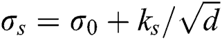 (where: σs is the yield strength; d is the average grain size; σ0 is the shear stress of lattice slip; ks is Hall-Petch constant, which is the resistance of the dislocation across the grain boundary). The smaller the grain size, the higher the yield strength; the coarser grains, fewer grains subjected to cyclic shear stress per unit volume, and uneven deformation which promotes the formation and propagation of cracks. The grain size of M1 is about 5 μm. After heat treatment, the grain size in M2 increases, M3 has a very long crystal arm, and there is no obvious grain boundary in M4. As the heat treatment temperature increases, the grain size gradually increases. At the same number of cycles, cracks in M4 are more likely to form and propagate, making failure the most serious.
In this paper, the rolling contact fatigue behaviors of Inconel 625 laser cladding coatings before and after heat treatments have been compared, while the contact stress of coating has also been analyzed by finite element simulation. The following conclusions are obtained:
1. Through the finite element analysis, the depth of maximum shear stress of laser cladding Inconel 625 coating is 92 μm. The depth of maximum shear stress is far from the interface between the substrate and the coating, therefore, the influence of the interface on its rolling fatigue failure mode can be ignored.
2. The formation of carbides, dispersed strengthening phases and brittle phases in the laser cladding coatings have been promoted by the heat treatments. During the contact fatigue test, the brittle phases broke, the dispersed phases contributed to the formation of pores, and the chain-shaped carbides has accelerated cracks growth and resulted in spalling, thereby reducing contact fatigue properties of Inconel 625 coatings. In addition, the increase of grain sizes after heat treatment has also contributed to the decrease in the yield strength, which made it easier to achieve rolling contact failure conditions. Heat treatments have impacts on the hardness and strength of the coating. Therefore, under the criterion of maximum shear stress, the status of the subsurface reaching the failure degree has differed due to different heat treatment methods. This is the main reason for the different surface failure morphology and cracks distribution.
3. For the laser cladding Inconel 625 coating, under rolling contact fatigue conditions, a series of metallographic changes caused by heat treatments have negative effects, which outweighs the benefits of stress releasing and microstructure homogenization, so no post-heat treatment is required.
Acknowledgement: This work was financially supported by the National Natural Science Foundation of China (No. 51875425) and Open Fund of Shandong Key Laboratory of Corrosion Science (No. KLCS201907).
Funding Statement: The authors gratefully acknowledge Chen Zhou from the Wuhan University of Technology for improving English writing.
Conflicts of Interest: The authors declare that they have no conflicts of interest to report regarding the present study.
1. Li, X., Shi, T., Li, B., Chen, X., Zhang, C. et al. (2019). Subtractive manufacturing of stable hierarchical micro-nano structures on AA5052 sheet with enhanced water repellence and durable corrosion resistance. Materials & Design, 183, 108152. DOI 10.1016/j.matdes.2019.108152. [Google Scholar] [CrossRef]
2. Xu, J. S., Zhang, X. C., Xuan, F. Z., Wang, Z. D., Tu, S. T. (2014). Rolling contact fatigue behavior of laser cladded WC/Ni composite coating. Surface & Coatings Technology, 239, 7–15. DOI 10.1016/j.surfcoat.2013.11.005. [Google Scholar] [CrossRef]
3. Li, X., Liang, J., Shi, T., Yang, D., Chen, X. et al. (2020). Tribological behaviors of vacuum hot-pressed ceramic composites with enhanced cyclic oxidation and corrosion resistance. Ceramics International, 46(9), 12911–12920. DOI 10.1016/j.ceramint.2020.02.057. [Google Scholar] [CrossRef]
4. Alam, M. K., Mehdi, M., Urbanic, R. J., Edrisy, A. (2020). Electron Backscatter Diffraction (EBSD) analysis of laser-cladded AISI 420 martensitic stainless steel. Materials Characterization, 161, 110138. DOI 10.1016/j.matchar.2020.110138. [Google Scholar] [CrossRef]
5. Wang, W. J., Fu, Z. K., Cao, X., Guo, J., Liu, Q. Y. et al. (2016). The role of lanthanum oxide on wear and contact fatigue damage resistance of laser cladding Fe-based alloy coating under oil lubrication condition. Tribology International, 94, 470–478. DOI 10.1016/j.triboint.2015.10.017. [Google Scholar] [CrossRef]
6. Wang, W. J., Hu, J., Guo, J., Liu, Q. Y., Zhu, M. H. (2014). Effect of laser cladding on wear and damage behaviors of heavy-haul wheel/rail materials. Wear, 311(1–2), 130–136. DOI 10.1016/j.wear.2014.01.011. [Google Scholar] [CrossRef]
7. Wang, W. J., Fu, Z. K., Guo, J., Zhang, Y. Q., Liu, Q. Y. et al. (2016). Investigation on wear resistance and fatigue damage of laser cladding coating on wheel and rail materials under the oil lubrication condition. Tribology Transactions, 59(5), 810–817. DOI 10.1080/10402004.2015.1107926.
8. Fu, Z. K., Ding, H. H., Wang, W. J., Liu, Q. Y., Guo, J. et al. (2015). Investigation on microstructure and wear characteristic of laser cladding Fe-based alloy on wheel/rail materials. Wear, 330, 592–599. DOI 10.1016/j.wear.2015.02.053.
9. Guo, H. M., Wang, Q., Wang, W. J., Guo, J., Liu, Q. Y. et al. (2015). Investigation on wear and damage performance of laser cladding Co-based alloy on single wheel or rail material. Wear, 328, 329–337. DOI 10.1016/j.wear.2015.03.002. [Google Scholar] [CrossRef]
10. Piao, Z. Y., Xu, J., Yin, L. Z., Wen, D. H., Xu, B. S. et al. (2016). Surface integrity design of plasma sprayed coating for resisting contact fatigue. Materials Chemistry and Physics, 179, 174–181. DOI 10.1016/j.matchemphys.2016.05.025. [Google Scholar] [CrossRef]
11. Piao, Z. Y., Xu, B. S., Wang, H. D., Wen, D. H. (2013). Influence of surface roughness on rolling contact fatigue behavior of Fe-Cr alloy coatings. Journal of Materials Engineering and Performance, 22(3), 767–773. DOI 10.1007/s11665-012-0315-z. [Google Scholar] [CrossRef]
12. Piao, Z., Xu, B., Wang, H., Pu, C. (2010). Influence of undercoating on rolling contact fatigue performance of Fe-based coating. Tribology International, 43(1–2), 252–258. DOI 10.1016/j.triboint.2009.05.028. [Google Scholar] [CrossRef]
13. Nakajima, A., Mawatari, T., Yoshida, M., Tani, K., Nakahira, A. (2000). Effects of coating thickness and slip ratio on durability of thermally sprayed WC cermet coating in rolling/sliding contact. Wear, 241(2), 166–173. DOI 10.1016/S0043-1648(00)00371-9. [Google Scholar] [CrossRef]
14. Fujii, M., Ma, J., Yoshida, A., Shigemura, S., Tani, K. (2006). Influence of coating thickness on rolling contact fatigue of alumina ceramics thermally sprayed on steel roller. Tribology International, 39(11), 1447–1453. DOI 10.1016/j.triboint.2006.01.013. [Google Scholar] [CrossRef]
15. Ramalingam, S., Zheng, L. S. (1995). Film-substrate interface stresses and their role in the tribological performance of surface-coatings. Tribology International, 28(3), 145–161. DOI 10.1016/0301-679X(95)98963-E. [Google Scholar] [CrossRef]
16. Piao, Z. Y., Xu, B. S., Wang, H. D., Pu, C. H. (2010). Investigation of rolling contact fatigue lives of Fe–Cr alloy coatings under different loading conditions. Surface & Coatings Technology, 204(9–10), 1405–1411. DOI 10.1016/j.surfcoat.2009.09.035. [Google Scholar] [CrossRef]
17. Savrai, R. A., Makarov, A. V., Soboleva, N. N., Malygina, I. Y., Osintseva, A. L. (2016). The behavior of gas powder laser clad NiCrBSi coatings under contact loading. Journal of Materials Engineering and Performance, 25(3), 1068–1075. DOI 10.1007/s11665-016-1925-7. [Google Scholar] [CrossRef]
18. Chen, Z. K., Meng, C., Dong, J. X., Zhou, T., Tong, X. et al. (2016). The comparative study of W/Cr addition in Fe-base by laser surface alloying on fatigue wear resistance of GCI. Surface & Coatings Technology, 286, 25–35. DOI 10.1016/j.surfcoat.2015.12.009. [Google Scholar] [CrossRef]
19. Roy, T., Lai, Q., Abrahams, R., Mutton, P., Paradowska, A. et al. (2018). Effect of deposition material and heat treatment on wear and rolling contact fatigue of laser cladded rails. Wear, 412, 69–81. DOI 10.1016/j.wear.2018.07.001. [Google Scholar] [CrossRef]
20. Feng, K., Chen, Y., Deng, P., Li, Y., Zhao, H. et al. (2017). Improved high-temperature hardness and wear resistance of Inconel 625 coatings fabricated by laser cladding. Journal of Materials Processing Technology, 243, 82–91. DOI 10.1016/j.jmatprotec.2016.12.001. [Google Scholar] [CrossRef]
21. Fang, X. Y., Li, H. Q., Wang, M., Li, C., Guo, Y. B. (2018). Characterization of texture and grain boundary character distributions of selective laser melted Inconel 625 alloy. Materials Characterization, 143, 182–190. DOI 10.1016/j.matchar.2018.02.008. [Google Scholar] [CrossRef]
22. Chen, Y., Guo, Y., Xu, M., Ma, C., Zhang, Q. et al. (2019). Study on the element segregation and Laves phase formation in the laser metal deposited IN718 superalloy by flat top laser and gaussian distribution laser. Materials Science and Engineering: A-Structural Materials Properties Microstructure and Processing, 754, 339–347. DOI 10.1016/j.msea.2019.03.096. [Google Scholar] [CrossRef]
23. Barr, C., Da Sun, S., Easton, M., Orchowski, N., Matthews, N. et al. (2018). Influence of macrosegregation on solidification cracking in laser clad ultra-high strength steels. Surface & Coatings Technology, 340, 126–136. DOI 10.1016/j.surfcoat.2018.02.052. [Google Scholar] [CrossRef]
24. Zhou, C., Jin, D., Zhang, Q., Yu, J. (2019). Adverse effects of post-heat treatment on the interfacial bonding strength of direct laser deposition Inconel 625/1045 composites. RSC Advances, 9(18), 10064–10071. DOI 10.1039/C8RA10149C. [Google Scholar] [CrossRef]
25. Marchese, G., Lorusso, M., Parizia, S., Bassini, E., Lee, J. W. et al. (2018). Influence of heat treatments on microstructure evolution and mechanical properties of Inconel 625 processed by laser powder bed fusion. Materials Science and Engineering: A-Structural Materials Properties Microstructure and Processing, 729, 64–75. DOI 10.1016/j.msea.2018.05.044. [Google Scholar] [CrossRef]
26. Zhang, X. C., Xu, B. S., Xuan, F. Z., Tu, S. T., Wang, H. D. et al. (2008). Rolling contact fatigue behavior of plasma-sprayed CrC-NiCr cermet coatings. Wear, 265(11–12), 1875–1883. DOI 10.1016/j.wear.2008.04.048. [Google Scholar] [CrossRef]
27. Miyashita, Y., Yoshimura, Y., Xu, J. Q., Horikoshi, M., Mutoh, Y. (2003). Subsurface crack propagation in rolling contact fatigue of sintered alloy. JSME International Journal, 46(3), 341–347. DOI 10.1299/jsmea.46.341. [Google Scholar] [CrossRef]
28. Walvekar, A. A., Sadeghi, F. (2017). Rolling contact fatigue of case carburized steels. International Journal of Fatigue, 95, 264–281. DOI 10.1016/j.ijfatigue.2016.11.003. [Google Scholar] [CrossRef]
29. Perricone, M. J., Dupont, J. N. (2006). Effect of composition on the solidification behavior of several Ni-Cr-Mo and Fe-Ni-Cr-Mo alloys. Metallurgical and Materials Transactions: A-Physical Metallurgy and Materials Science, 37(4), 1267–1280. DOI 10.1007/s11661-006-1078-7. [Google Scholar] [CrossRef]
30. Ola, O. T., Doern, F. E. (2014). A study of cold metal transfer clads in nickel-base INCONEL 718 superalloy. Materials & Design, 57, 51–59. DOI 10.1016/j.matdes.2013.12.060. [Google Scholar] [CrossRef]
31. Xing, X., Di, X., Wang, B. (2014). The effect of post-weld heat treatment temperature on the microstructure of Inconel 625 deposited metal. Journal of Alloys and Compounds, 593, 110–116. DOI 10.1016/j.jallcom.2013.12.224. [Google Scholar] [CrossRef]