Materials
| Journal of Renewable Materials |
DOI: 10.32604/jrm.2021.015553
ARTICLE
Fabrication and Simulation of TE Modules for a Feasibility Study on Harvesting Solar Heat Energy from Roof Tiles
1Solar Energy and Energy Resources Research Unit, Faculty of Engineering, Mahasrakham University, Khamriang, 44150, Thailand
2Program of Physics, Faculty of Science and Technology, Thermoelectric Research Laboratory, Center of Excellence on Alternative Energy, Research and Development Institution, Sakon Nakhon Rajabhat University, Sakon Nakhon, 47000, Thailand
*Corresponding Authors: Jindaporn Jamradloedluk. Email: jindaporn.msu@gmail.com; Tosawat Seetawan. Email: t_seetawan@snru.ac.th
Received: 26 December 2020; Accepted: 26 February 2021
Abstract: A novel roof tile thermoelectric generator (RT-TEG) was used to harvest electrical energy from a solar heat source. The RT-TEG was fabricated and simulated by flat and curved thermoelectric modules consisting of p-n junctions of p-Sb2Te3 and n-Bi2Te3, with an Al2O3 substrate at the top and bottom for heat absorption and heat rejection. The RT-TEG was installed in a roof tile to act as a generator. The electrical voltage and power values of the curved thermoelectric modules were higher than those of the flat thermoelectric module by 0.44 V and 80 mW, at a temperature difference (ΔT) of 100 K. In field tests, the RT-TEG produced a maximum electrical voltage of 33.70 mV and an electrical power of 46.24 μW at ΔT~7 K under a load resistance of 1 Ω under good sunshine at 13.00 hours. The energy conversion efficiency of RT-TEG was found to be 2.24 × 10⁻⁴.
Keywords: Roof tiles micro-generator; alternative energy; thermoelectric module; harvesting energy; conversion energy
Due to depletion and environmental effect of fossil fuels, renewable energy such as solar cell, wind [1], and bio-oil [2] has been more increasingly used. Thermoelectric (TE) is a device for a conversion of waste heat to electricity. It has various applications, i.e. wood stoves, natural gas use, vehicles, and solar heating [3–7]. A TE device is fabricated by using p- and n-type TE materials to form a p-n junction. The device has two applications: (1) A TEG, wherein electricity is generated by the Seebeck effect, and (2) Thermoelectric cooling (TEC), wherein an electrical current is applied to a p-n junction couple (the so-called Peltier effect). In both cases, the TE device offers the advantages of having no moving parts, no noise production, a long cycle duration, low maintenance cost, and environmental friendliness. A Bi2Te3-based TEG has been fabricated that operates in the low-temperature range (<623 K). Commercial preparation of bulk involves melting and quenching operations to create the desired phase composition in sealed quartz tubes, followed by crushing the materials to a powder and hot pressing [8–10]. High-performance TE materials have been obtained by preparing nanoparticles from raw materials: Rapid spark plasma sintering has been used to produce nanoparticles that exhibit increased phonon scattering and decreased thermal conductivity [11–15]. The power factor of TE materials is defined as PF = S2/ρ, where S2/ρ, S, ρ, and T represent the power factor, the Seebeck coefficient, the electrical resistivity, and the absolute temperature, respectively.
A TE module is typically fabricated with a flat shape, where rigid ceramic substrate shapes, such as aluminum oxide (Al2O3) and aluminum nitride (AlN), are used to create a flat surface. However, a flat TE module cannot generate all the electricity available from a curved heat surface. Consequently, many flexible substrate materials, such as silk fabric, polyimide films, and glass fabric, are currently being developed for use with curved heat surfaces and conducting TE materials. Various approaches have been used to fabricate flexible substrates: Lu et al. fabricated a TE module by using silk fabric as a flexible substrate and Bi2Te3 mixed with a binder as TE materials to harvest electricity from the human body. A TE module consisting of 20 couples produced 2.08 µW at ΔT = 303 K. When the flexible TEG was attached to the human body (at the chest), a power output of 178 nW was obtained at an ambient temperature of 278 K [16]. Francioso et al. successfully used RF magnetron cosputtering to fabricate a flexible TEG with a total size of 70 × 30 mm2 by depositing Bi2Te3 and Sb2Te3 thin films on Kapton HN polyimide foil. The internal resistance of the device consisting of 100 thermocouples was 380 kΩ. An open-circuit voltage and a maximum output power of 430 mV and 32 nW, respectively, were generated at = 313 K [17]. Kim et al. successfully prepared a flexible TEG by successively screen printing Bi2Te3 and Sb2Te3 pastes onto glass fabric, followed by annealing at 803 K and 773 K, respectively, in a N2 atmosphere. The 11 as-prepared band-type flexible TEG thermocouples generated an open-circuit voltage and an output power of 2.90 mV and 3 µW, respectively, when worn on human skin at an environmental temperature of 288 K [18]. Kim et al. fabricated a self-powered wireless sensor node driven by a flexible TEG for use with a heat pipe. A total energy of 272 mW were harvested over a curved area of 140 × 113 mm2 from the heat pipe at a temperature of 343 K. They also tested a complete self-powered 34 WSN system for remote monitoring of heat pipe temperature, ambient temperature, humidity, CO2 and volatile organic compounds [19]. However, the main problem encountered with using a flexible substrate was low heat transfer between the substrate and the surface at the cooling side and substrate deformation at nearly 573 K. Luo et al. conducted a study on a solar thermoelectric generator using phase change materials (PCMs) to absorb heat from solar radiation. A maximum voltage of approximately 2.697 V was obtained at 80°C using the PCMs [20]. Muthu et al. investigated the performance of a solar-parabolic-dish thermoelectric generator based on PCMs. The solar parabolic dish exhibited a maximum temperature of approximately 120°C with a solar beam radiation of 1,100 W m−2. A maximum power of 1 W was obtained from the TEG at an 80°C temperature difference [21]. Lv et al. fabricated high-performance terrestrial solar thermoelectric generators without optical concentration for use on residential and commercial rooftops. The maximum peak exergy efficiency of the system reached a record value of 7.17% [22]. Maneewan et al. invented a TE-RSC composed of a transparent acrylic sheet, an air gap, a copper plate, thermoelectric modules, and a rectangular fin heat sink, which was tested under the design conditions. The test results showed that the TE-RSC generated approximately 1 W at a simulated solar intensity of 800 W m−2 at ambient temperatures between 30 and 35°C. This TE-RSC could drive a fan to cool the cold side of thermoelectric modules [23]. Zheng et al. studied a thermoelectric cogeneration system (TCS) that enhances sustainability by improving energy efficiency in the domestic sector, which was compared with other components of a thermoelectric system. The thermoelectric block included 16 modules, a cold side, and a hot-side heat exchanger. Each module was made of Bi2Te3 with dimensions of 40 × 40 × 3.8 mm3 and 127 thermocouples. The system viability was assessed in terms of the maximal recovery of available boiler waste heat and solar radiation. A maximum conversion efficiency of approximately 4% was obtained when the temperature difference increased to 130°C [24].
In this study, a RT-TEG was fabricated by using a TE device made of p-Sb2Te3 and n-Bi2Te3 base materials. The thermoelectric properties of the TE materials were measured to comparatively analyze the performance of curved and flat modules. The potential application of the RT-TEG was evaluated by measuring the electricity generated from different surfaces in a real environment.
TE curved and flat modules were simulated using ANSYS finite element (FE) software to predict the Joule heating value, the Seebeck coefficient, the Peltier coefficient, and the generated thermoelectricity [25]. The heat flow equations and the continuity equations of the electric charges in a system of TE devices are given by Eqs. (1) and (2) [25,26]:
where
where
where
where
The Galerkin method was used to convert the thermoelectric equation into a system of thermoelectric finite element (FEM) equations [27,28]. The temperature and scalar electric potential in the FEM system are approximated by
where
The FEM model was used to design a curved substrate for TE curved and flat modules with dimensions of 30 × 30 × 0.8 mm3 and a 4 × 4 × 6 mm3 p-n couple of 11 pairs. The element size of the TE curved and flat modules was set to 0.4 mm, for which the ANSYS simulation software automatically generated 411,177 nodes/81,228 elements and 369,025 nodes/72,255 elements, respectively, as shown in Figs. 1a and 1c. The basic calculation parameters of the TE modules were assigned in the materials model tabulated in Tab. 1. A temperature gradient of 274–373 K was applied to the top side of the TE modules, and the bottom-side temperature was set at 295 K, as depicted in Figs. 1b and 1d. A load resistance was connected the first p-type TE module and the last n-type TE module and used to determine the electrical power.

Figure 1: Design model of thermoelectric module: (a) Curved module and mesh, (b) Depiction of temperature gradient of curved modules, (c) Flat module and mesh, (d) Depiction of temperature gradient of flat modules; where calculations are performed using ANSYS for TH = 395 K and TC = 295 K
Table 1: Basic simulation parameters of TE modules
2.2 Fabrication of TE Modules and Measurement of Electricity Power Generation
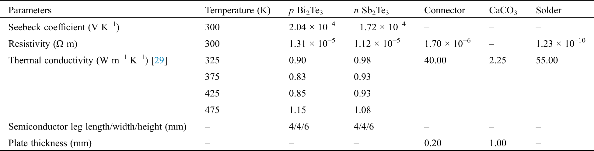
The TE curved and flat modules were fabricated from 11 pairs of p-Sb2Te3 and n-Bi2Te3 junctions with dimensions of 4.0 × 4.0 × 6.0 mm3 (Wuhan Xinrong New Materials Co. Ltd. of China); Tab. 1 shows the TE properties measured at room temperature using a ZEM-3 (UNVAC-RIKO, Japan). Fig. 2a is a schematic circuit for TE modules designed by Solid Work 2020, consisting of 11 p-n pairs connected in series with a 4 × 10 × 0.05 mm3 silver electrode. Curved and flat substrates were fabricated by pressing CaCO3 under 60 MPa into a 0.8–1.0 mm thickness, followed by sintering at 1,573 K in air. An Ag electrode was fabricated on the substrates by screen coating Ag paste onto the ceramic substrate, followed by drying at 423 K for 1 h and annealing at 1,073 K for 30 min in air. The TE legs and the Ag electrode were soldered with lead free-solder (Sn/96.5%, Ag/3%, and Cu/0.5%), where the fabricated TE modules as presented in Figs. 2b and 2c.
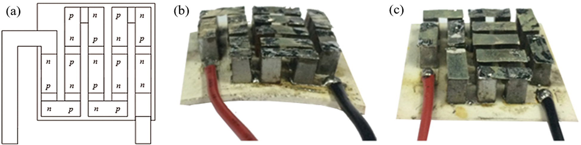
Figure 2: (a) Schematic circuit of TE modules; (b) Curved and (c) Flat fabricated TE modules
Fig. 3a is a schematic of an apparatus for measuring the electricity generated by the TE curved and flat modules that was designed using the thermoelectric consensual steady-state method. The measurement systems for the electricity generated by the TE curved and flat modules were set up following the schematic design for a
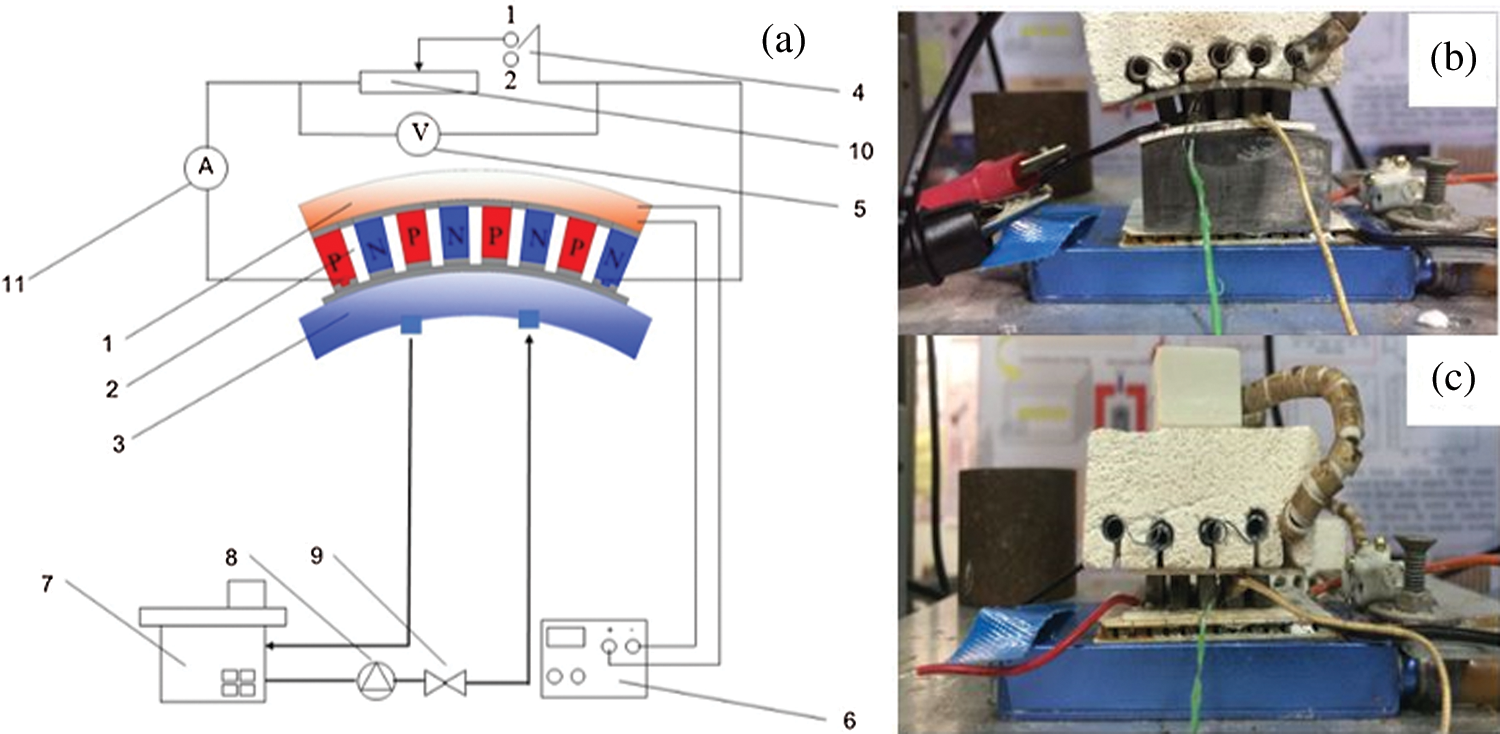
Figure 3: (a) Schematic for measuring electricity generation from flat and curved modules, where numbers denote system components: 1-heater, 2-TE module, 3-cooling system, 4-SPDT switch, 5-voltmeter, 6-PID electrical system, 7-constant temperature reservoir, 8-pump, 9-valve, 10-variable resistor, 11-amperemeter; (b) Curved module; and (c) Flat module
2.3 Fabrication of RT-TEG and Measurement of Electricity Power Generation
The RT-TEG was fabricated from curved and flat modules connected in series between p and n junctions that were filled with silicon to prevent heat loss and short circuiting; the bottom of the cold side was covered with aluminum foil to promote cooling as shown in Fig. 4(a). The RT-TEG was applied in a real situation, i.e., roof tile in a home. To consider the effects of the wind speed and temperature under the roof tile (See Fig. 4b), the experiments were conducted in triplicate for reliability.
Figure 4: (a) TE consisting of curved and flat modules installed in roof tiles and (b) RT-TEG test station
2.4 Energy Conversion Efficiency of the System
One of the indicator to describe the performance of the RT-TEG is energy conversion efficiency. It was analyzed using Eq. (8).
3.1 Simulation and Experiments for TE Modules
The comparative discussion on the results from curved and flat modules are presented in Tab. 2. It can be seen that voltage derived from both modules are comparable and electrical power obtained from the curved module are slightly higher than that obtained from the flat module. Such a higher power is because the curve module provides the larger temperature difference which is a driving force for power generation.
Table 2: The comparative discussion on the results from curved and flat modules tested at temperature difference of 373 K and load resistance of 1 Ω

The temperature-dependent TE properties of the n-Bi2Te3 and p-Sb2Te3 materials are shown in Figs. 5a and 5b, respectively. In Fig. 5a, the S values of n-Bi2Te3 decrease with increasing temperature from −250 µV K–1 at 310 K to −263 µV K–1 at 380 K. However, these values are higher than those reported by Go-Eun Lee et al. [19]. In Fig. 5b, the S value of p-Sb2Te3 increased with the temperature from 255 µV K–1 at 310 K to 268 µV K–1 at 380 K. The negative and positive values of S reflected the semiconducting behavior of the n-type and p-type TE materials, respectively. By contrast,
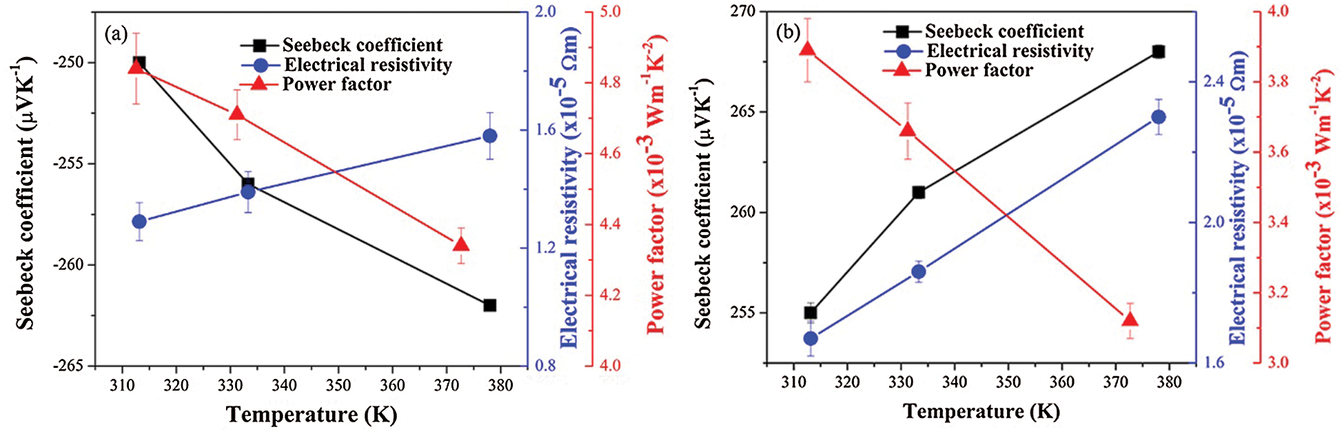
Figure 5: Temperature-dependent Seebeck coefficient, electrical resistivity and power factor of (a) n-type and (b) p-type materials
The voltage distribution of the TE curved and flat modules was simulated by setting constant temperatures of 395 K at the hot side and 295 K at the cold side and a 1-ohm external load resistance, as depicted in Figs. 6a and 6b, respectively. Similar evenly distributed voltage distributions were obtained for both modules, in agreement with Kossyvakis’ results [30].
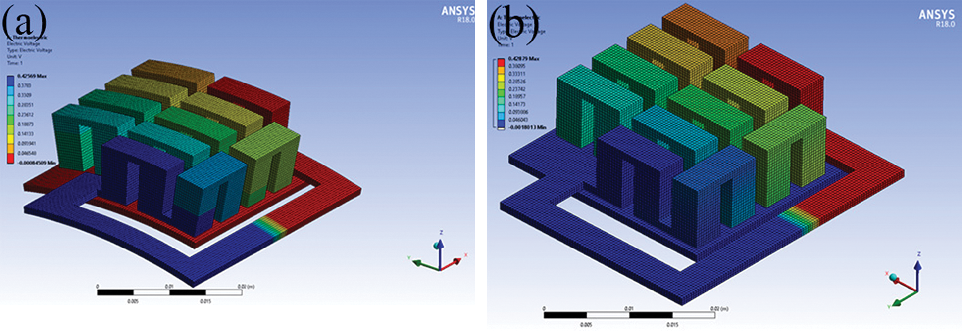
Figure 6: FEM results for voltage distribution of (a) Curved and (b) Flat modules for TH = 395 K, TC = 295 K and RL = 1 Ω
The simulated and experimental open circuit voltage for the curved TE module increased with the temperature and exhibited different maximum values of approximately 0.44V and 0.42V at 373 K, respectively, as shown in Fig. 7a. The simulated and experimental open circuit voltage for the flat TE module increased with the temperature and exhibited different maximum values of approximately 0.44 V and 0.43 V at 373 K, respectively, as shown in Fig. 7b. Thus, the simulated open circuit voltages for the curved and flat TE modules differed by approximately 5–10% from the experimental values. Performing the experiments in an ambient atmosphere introduces error into the voltage measurement of the TE modules. However, this measurement is used to predict the real voltage and power for use in field studies. Moreover, the curved TE module exhibits good harvesting of heat energy from a curved substrate, which is similar to that of the flat TE module and shows the feasibility of using a curved module with a curved substrate.
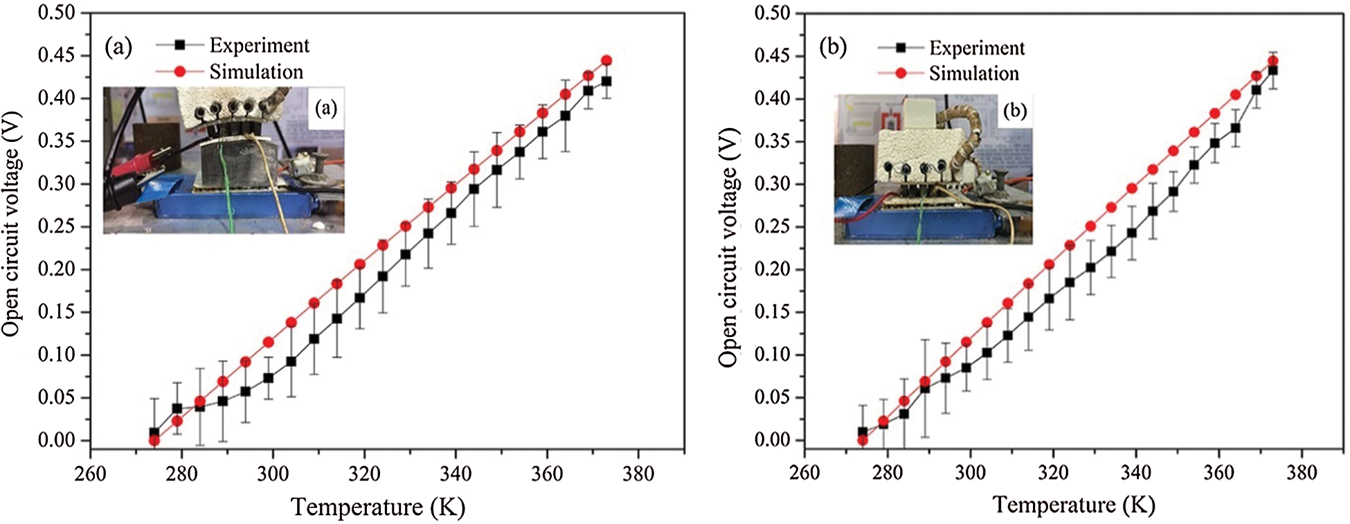
Figure 7: Comparison of measured and simulated results for open circuit voltage at outlet of (a) Curved modules and (b) Flat modules
The voltage and power of the curved and flat TE modules were measured at a
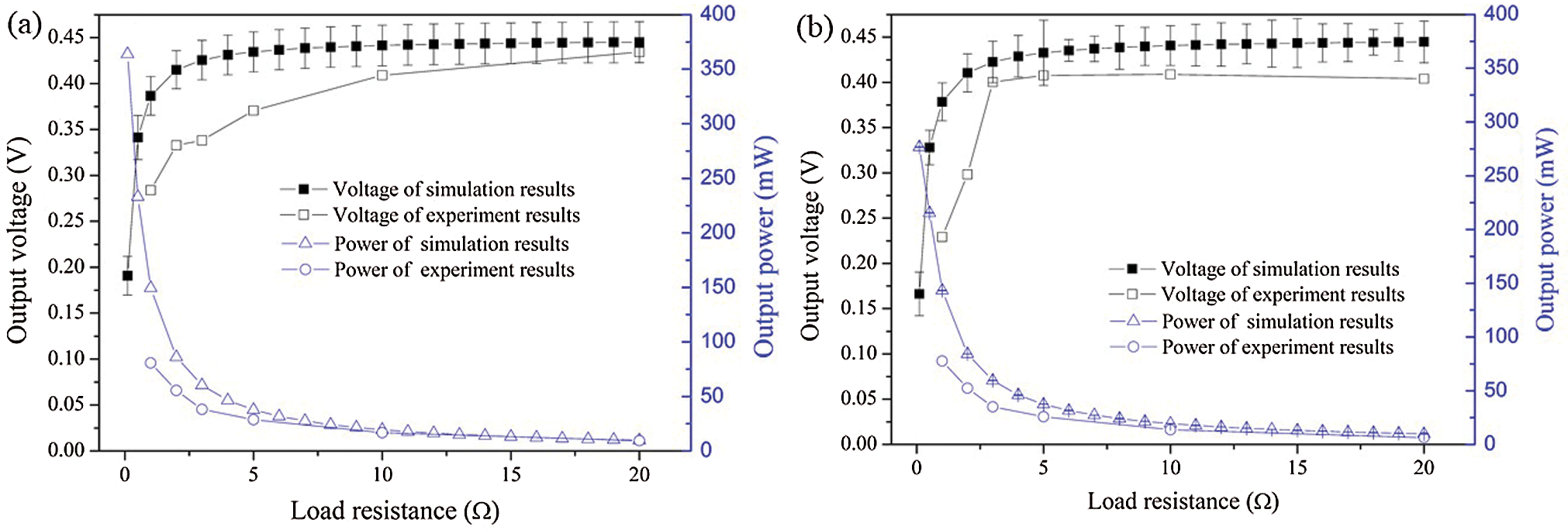
Figure 8: Comparison of numerically simulated and experimental voltage, power, and load resistance between (a) Curved and (b) Flat modules
Fig. 9 presents the daylight solar radiation and the corresponding temperature for roof tile during the experimental test, including the top-side temperature, the bottom-side temperature, and the induced temperature difference. The solar radiation at the start of daylight was approximately 200 Wm−2 at 06.00 hours, which induced a temperature difference of 1 K, and increased to a maximum of approximately 1,000 Wm−2 at 12.00–13.30 hours for a temperature difference of approximately 7 K. Clouds moved in at 14.30 hours, thereby decreasing the radiation intensity: The temperature was calculated using the Stefan-Boltzmann law for a diffuse black body system to be
where
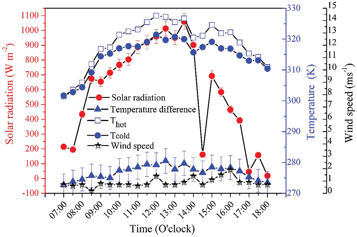
Figure 9: Relationship among solar radiation, temperature and wind speed obtained from field tests
Fig. 10 indicates how the different temperatures, power, and voltage of the RT-TEG varied during a field test conducted from 07.00–18.00 h. The different temperatures, power, and voltage increased with time until 13.00 h and then decreased. The maximum voltage and power of approximately 6.8 V and 46.24 μW, respectively, occurred at 13.00 h. Although, the power output was rather low, the results of the study are useful when using the large area, where the power output depends on the number of TE modules. Energy conversion efficiency of the system was also evaluated and it was found to be 2.24 × 10⁻⁴.
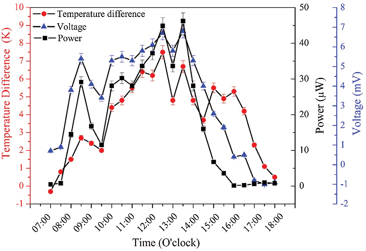
Figure 10: Electrical power and voltage of RT-TEG measured in field test
In this study, curved and flat modules were successfully fabricated from p-Sb2Te3 and n-Bi2Te3 materials. A single-phase microstructure was obtained, and the measured TE properties for the p- and n-type materials corresponded with literature data. The maximum voltages of the curved and flat TE modules were approximately 0.44 V and 0.42 V, respectively, over a load resistance of 1–20 Ω. The power of the curved and flat TE modules decreased as the load resistance increased, in agreement with simulation results, and exhibited maximum values of approximately 80 mW and 77 mW, respectively at matching load resistances of 1 Ω. The solar intensity, electrical voltage, and power output of the RT-TEG measured in field tests increased with time until 1:30 pm and then decreased. The maximum voltage and power output of the RT-TEG were approximately 6.80 mV and 46.24 μW, respectively, under a load resistance of 1 Ω and the solar intensity of 1,059.40 W m−2. Thus, it is feasible to use curved and flat modules in roof tile: The number of modules can be increased to cover the entire surface area to increase electric power generation, and these modules could also be installed on other curved areas, such as in a furnace tube.
Funding Statement: This work has financial supported by the Thailand Research Fund (TRF) Research Career Development Grant: (RSA6180070).
Conflicts of Interest: The authors declare that they have no conflicts of interest to report regarding the present study.
1. Pesch, U., Correljé, A., Cuppen, E., Taebi, B., van de Grift, E. (2017). Formal and informal assessment of energy technologies. In: Asveld, L., van Dam-Mieras, R., Swierstra, T., Lavrijssen, S., Linse, K., van den Hoven, J. (eds.Responsible innovation. vol. 3, pp. 131–148. Cham: Springer. [Google Scholar]
2. Deng, W., Xu, K., Xiong, Z., Chaiwat, W., Wang, X. et al. (2019). Evolution of aromatic structures during the low-temperature electrochemical upgrading of bio-oil. Energy & Fuels, 33(11), 11292–11301. DOI 10.1021/acs.energyfuels.9b03099. [Google Scholar] [CrossRef]
3. Goudarzi, A. M., Mazandarani, P., Panahi, R., Behsaz, H., Rezania, A. et al. (2013). Integration of thermoelectric generators and wood stove to produce heat, hot water, and electrical power. Journal of Electronic Materials, 42(7), 2127–2133. DOI 10.1007/s11664-013-2545-8. [Google Scholar] [CrossRef]
4. O’Shaughnessy, S. M., Deasy, M. J., Kinsella, C. E., Doyle, J. V., Robinson, A. J. (2013). Small scale electricity generation from a portable biomass cookstove: Prototype design and preliminary results. Applied Energy, 102(5726), 374–385. DOI 10.1016/j.apenergy.2012.07.032. [Google Scholar] [CrossRef]
5. Shittu, S., Li, G., Akhlaghi, Y. G., Ma, X., Zhao, X. et al. (2019). Advancements in thermoelectric generators for enhanced hybrid photovoltaic system performance. Renewable and Sustainable Energy Reviews, 109(590), 24–54. DOI 10.1016/j.rser.2019.04.023. [Google Scholar] [CrossRef]
6. Choi, Y., Negash, A., Kim, T. Y. (2019). Waste heat recovery of diesel engine using porous medium-assisted thermoelectric generator equipped with customized thermoelectric modules. Energy Conversion and Management, 197(116), 111902. DOI 10.1016/j.enconman.2019.111902. [Google Scholar] [CrossRef]
7. Abbasi, V., Tabar, V. S. (2020). Measurement and evaluation of produced energy by thermoelectric generator in vehicle. Measurement, 149(4), 107035. DOI 10.1016/j.measurement.2019.107035. [Google Scholar] [CrossRef]
8. You, H. J., Chu, H. S., Li, W. J., Lee, W. L. (2019). Influence of different substrate materials on thermoelectric module with bulk legs. Journal of Power Sources, 438, 227055. DOI 10.1016/j.jpowsour.2019.227055. [Google Scholar] [CrossRef]
9. Wu, F., Wang, W., Hu, X., Tang, M. (2017). Thermoelectric properties of I-doped n-type Bi2Te3-based material prepared by hydrothermal and subsequent hot pressing. Progress in Natural Science: Materials International, 27(2), 203–207. DOI 10.1016/j.pnsc.2017.02.009. [Google Scholar] [CrossRef]
10. Mei, D., Wang, H., Yao, Z., Li, Y. (2018). Ultrasonic-assisted hot pressing of Bi2Te3-based thermoelectric materials. Materials Science in Semiconductor Processing, 87, 126–133. DOI 10.1016/j.mssp.2018.07.019. [Google Scholar] [CrossRef]
11. Lv, T., Li, Z., Liu, Y., He, J., Zhou, D. et al. (2019). Improving thermoelectric performance of (Bi0.2Sb0.8)2 (Te0.97Se0.03)3 via Sm-doping. Journal of Alloys and Compounds, 787, 909–917. DOI 10.1016/j.jallcom.2019.02.187. [Google Scholar] [CrossRef]
12. An, J., Han, M. K., Kim, S. J. (2019). Synthesis of heavily Cu-doped Bi2Te3 nanoparticles and their thermoelectric properties. Journal of Solid State Chemistry, 270, 407–412. DOI 10.1016/j.jssc.2018.11.024. [Google Scholar] [CrossRef]
13. Min, B., Lim, S. S., Jung, S. J., Kim, G., Lee, B. H. et al. (2018). Texture-induced reduction in electrical resistivity of p-type (Bi,Sb)2Te3 by a hot extrusion. Journal of Alloys and Compounds, 764, 261–266. DOI 10.1016/j.jallcom.2018.06.026. [Google Scholar] [CrossRef]
14. Li, D., Qin, X. Y., Zhang, J., Song, C. J., Liu, Y. F. et al. (2015). Thermoelectric anisotropy of n-type Bi2 Te3−xSex prepared by spark plasma sintering. RSC Advances, 5(54), 43717–43722. DOI 10.1039/C5RA04435A. [Google Scholar] [CrossRef]
15. Jiang, J., Chen, L., Bai, S., Yao, Q., Wang, Q. (2005). Thermoelectric properties of textured p-type (Bi,Sb)2Te3 fabricated by spark plasma sintering. Scripta Materialia, 52(5), 347–351. DOI 10.1016/j.scriptamat.2004.10.038. [Google Scholar] [CrossRef]
16. Lu, Z., Zhang, H., Mao, C., Li, C. M. (2016). Silk fabric-based wearable thermoelectric generator for energy harvesting from the human body. Applied Energy, 164(5), 57–63. DOI 10.1016/j.apenergy.2015.11.038. [Google Scholar] [CrossRef]
17. Francioso, L., de Pascali, C., Farella, I., Martucci, C., Cretì, P. et al. (2011). Flexible thermoelectric generator for ambient assisted living wearable biometric sensors. Journal of Power Sources, 196(6), 3239–3243. DOI 10.1016/j.jpowsour.2010.11.081. [Google Scholar] [CrossRef]
18. Kim, S. J., We, J. H., Cho, B. J. (2014). A wearable thermoelectric generator fabricated on a glass fabric. Energy & Environmental Science, 7(6), 1959–1965. DOI 10.1039/c4ee00242c. [Google Scholar] [CrossRef]
19. Kim, Y. J., Gu, H. M., Kim, C. S., Choi, H., Lee, G. et al. (2018). High-performance self-powered wireless sensor node driven by a flexible thermoelectric generator. Energy, 162, 526–533. DOI 10.1016/j.energy.2018.08.064. [Google Scholar] [CrossRef]
20. Luo, X., Guo, Q., Tao, Z., Liang, Y., Liu, Z. (2020). Modified phase change materials used for thermal management of a novel solar thermoelectric generator. Energy Conversion and Management, 208, 112459. DOI 10.1016/j.enconman.2019.112459. [Google Scholar] [CrossRef]
21. Muthu, G., Thulasi, S., Dhinakaran, V., Mothilal, T. (2020). Performance of solar parabolic dish thermoelectric generator with PCM. Materials Today: Proceedings. [Google Scholar]
22. Lv, S., He, W., Hu, Z., Liu, M., Qin, M. et al. (2019). High-performance terrestrial solar thermoelectric generators without optical concentration for residential and commercial rooftops. Energy Conversion and Management, 196, 69–76. DOI 10.1016/j.enconman.2019.05.089. [Google Scholar] [CrossRef]
23. Maneewan, S., Khedari, J., Zeghmati, B., Hirunlabh, J., Eakburanawat, J. (2004). Investigation on generated power of thermoelectric roof solar collector. Renewable Energy, 29(5), 743–752. DOI 10.1016/j.renene.2003.10.005. [Google Scholar] [CrossRef]
24. Zheng, X. F., Yan, Y. Y., Simpson, K. (2013). A potential candidate for the sustainable and reliable domestic energy generation–Thermoelectric cogeneration system. Applied Thermal Engineering, 53(2), 305–311. DOI 10.1016/j.applthermaleng.2012.03.020. [Google Scholar] [CrossRef]
25. Antonova, E. E., Looman, D. C. (2005). Finite elements for thermoelectric device analysis in ANSYS. 24th International Conference on Thermoelectrics, pp. 215–218. IEEE. [Google Scholar]
26. Singsoog, K., Pilasuta, P., Paengson, S., Namhongsa, W., Ruamruk, S. et al. (2019). Theoretical simulation of thermoelectric generator consisting of n-Mg2Si and p-MnSi1.75 by finite element method. Materials Today: Proceedings, 17, 1437–1443. DOI 10.1016/j.matpr.2019.06.165. [Google Scholar] [CrossRef]
27. Benday, N. S., Dryden, D. M., Kornbluth, K., Stroeve, P. (2017). A temperature-variant method for performance modeling and economic analysis of thermoelectric generators: Linking material properties to real-world conditions. Applied Energy, 190(2), 764–771. DOI 10.1016/j.apenergy.2016.12.157. [Google Scholar] [CrossRef]
28. Hyland, M., Hunter, H., Liu, J., Veety, E., Vashaee, D. (2016). Wearable thermoelectric generators for human body heat harvesting. Applied Energy, 182(4), 518–524. DOI 10.1016/j.apenergy.2016.08.150. [Google Scholar] [CrossRef]
29. Lee, H., Sharp, J., Stokes, D., Pearson, M., Priya, S. (2018). Modeling and analysis of the effect of thermal losses on thermoelectric generator performance using effective properties. Applied Energy, 211, 987–996. DOI 10.1016/j.apenergy.2017.11.096. [Google Scholar] [CrossRef]
30. Kossyvakis, D. N., Vossou, C. G., Provatidis, C. G., Hristoforou, E. V. (2015). Computational and experimental analysis of a commercially available Seebeck module. Renewable Energy, 74(1–4), 1–10. DOI 10.1016/j.renene.2014.07.024. [Google Scholar] [CrossRef]
31. Rowe, D. M., Min, G. (1998). Evaluation of thermoelectric modules for power generation. Journal of Power Sources, 73(2), 193–198. DOI 10.1016/S0378-7753(97)02801-2. [Google Scholar] [CrossRef]
32. Chávez-Urbiola, E. A., Vorobiev, Y. V., Bulat, L. P. (2012). Solar hybrid systems with thermoelectric generators. Solar Energy, 86(1), 369–378. DOI 10.1016/j.solener.2011.10.020. [Google Scholar] [CrossRef]
33. Admasu, B. T., Luo, X., Yao, J. (2013). Effects of temperature non-uniformity over the heat spreader on the outputs of thermoelectric power generation system. Energy Conversion and Management, 76(12), 533–540. DOI 10.1016/j.enconman.2013.08.004. [Google Scholar] [CrossRef]
34. Xiao, J., Yang, T., Li, P., Zhai, P., Zhang, Q. (2012). Thermal design and management for performance optimization of solar thermoelectric generator. Applied Energy, 93, 33–38. DOI 10.1016/j.apenergy.2011.06.006. [Google Scholar] [CrossRef]
35. Liao, M., He, Z., Jiang, C., Li, Y., Qi, F. (2018). A three-dimensional model for thermoelectric generator and the influence of Peltier effect on the performance and heat transfer. Applied Thermal Engineering, 133, 493–500. DOI 10.1016/j.applthermaleng.2018.01.080. [Google Scholar] [CrossRef]
36. Bjørk, R., Nielsen, K. K. (2018). The maximum theoretical performance of unconcentrated solar photovoltaic and thermoelectric generator systems. Energy Conversion and Management, 156, 264–268. DOI 10.1016/j.enconman.2017.11.009. [Google Scholar] [CrossRef]
37. Hu, J., Yu, X. (2019). Thermo and light-responsive building envelope: Energy analysis under different climate conditions. Solar Energy, 193, 866–877. DOI 10.1016/j.solener.2019.10.021. [Google Scholar] [CrossRef]
38. Park, S. I., Ryu, T. H., Choi, I. C., Um, J. S. (2019). Evaluating the operational potential of LRV signatures derived from UAV imagery in performance evaluation of cool roofs. Energies, 12(14), 2787. DOI 10.3390/en12142787. [Google Scholar] [CrossRef]
39. Pisello, A. L., Rossi, F., Cotana, F. (2014). Summer and winter effect of innovative cool roof tiles on the dynamic thermal behavior of buildings. Energies, 7(4), 2343–2361. DOI 10.3390/en7042343. [Google Scholar] [CrossRef]
 | This work is licensed under a Creative Commons Attribution 4.0 International License, which permits unrestricted use, distribution, and reproduction in any medium, provided the original work is properly cited. |