DOI: 10.32604/jrm.2021.012253
ARTICLE
Damping Analysis and Failure Mechanism of 3D Printed Bio-Based Sandwich with Auxetic Core under Bending Fatigue Loading
1Acoustics Laboratory of Mans University (LAUM)-UMR CNRS, Le Mans University, Le Mans, 6613, France
2Laboratory of Mechanics Modeling and Production (LA2MP), National School of Engineers of Sfax, University of Sfax, Sfax, Tunisia
*Corresponding Author: Khawla Essassi. Email: khawlaessassi@gmail.com
Received: 22 June 2020; Accepted: 31 August 2020
Abstract: Meta-sandwich composites with three-dimensional (3D) printed architecture structure are characterized by their high ability to absorb energy. In this paper, static and fatigue 3-point bending tests are implemented on a 3D printed sandwich composites with a re-entrant honeycomb core. The skins, core and whole sandwich are manufactured using the same bio-based material which is polylactic acid with flax fiber reinforcement. Experimental tests are performed in order to evaluate the durability and the ability of this material to dissipate energy. First, static tests are conducted to study the bending behaviour of the sandwich beams, as well as to determine the failure parameters and the characteristic used in fatigue tests. Then, fatigue analyses were carried out to determine the fatigue resistance of these structures. The effects of the core density on the stiffness, hysteresis loop, energy absorption and loss factor, for two loading level, are determined. Moreover, the behaviour of this sandwich composite with re-entrant honeycomb core is compared with that of sandwiches with different core topologies. The results show that sandwich with high core density dissipate more energy, which results higher loss factors. The determined properties offer the most sensitive indicators of sandwich composite damage during its lifetime. This work aims to determine the static and fatigue properties of this material, thus, study its potential applications in industry.
Keywords: Auxetic structure; fatigue; damping; bio-sandwich composite; 3D printing
Sandwich composites have been widely used, over the past several decades, in different applications such as automotive, sports and leisure. The mechanical characteristics of the sandwich structure depend on the matrix and fiber reinforcement material used for its manufacturing, and especially on the core structural topology. The wide diversity in terms of structural design used as core material in the sandwich composite gave birth to different manufacturing techniques [1,2]. Recently, the additive manufacturing (3D printing) process is considered as one of the most advanced manufacturing techniques. It is widely used to produce complex geometry in many industrial areas [3–5]. When compared to traditional manufacturing techniques, 3D printing presents different benefits such as the ability to build complex structures, lower materials waste and lower costs [6]. It was also proven that parts manufactured with additive manufacturing present long-term durability [7] and efficiency [8] in aerospace industries. That’s why, researches are inclined towards the use of this method to build sandwich structures. 3D printed sandwich has proven that the major failure mode under compressive loading was the buckling of vertical pillars [9]. Soltani et al. [10] have used 3D printing technique to build on-water sports boards with bio-inspired core designs. It was found that bio-inspired functionally graded honeycomb structure presents the best bending performance. Also, 3D printing was controlled and tested in order to improve strength to weight ratio [11]. Structure printed which combined different materials showed excellent properties than those printed with a single material [12].
In recent years, environmental issues have driven the emergence of bio-based composites. These materials have become a subject of interest in numerous industrial fields [13]. They present numerous advantages such as biodegradability [14], recyclability [15] and a superior capacity to absorb energy [16]. Therefore, bio-based composite materials present an interesting alternative to conventional synthetic ones. The use of natural fibers is widely used to reduce the environmental impact. Flax fibers are the most commonly used in the literature [17]. They present advanced mechanical properties comparable to glass fibers [18]. In addition, flax fibers have been used in order to achieve superior mechanical properties [19,20]. Sandwich structures are widely used in order to improve the specific performance of composite materials. The presence of a light core enhances the quadratic moment, which improves the stiffness and strength of the structure. Monti et al. [21] studied the static and fatigue bending properties of a bio-based sandwich. An Elium/flax fiber composite was used for the skins and balsa wood was used as the core. They have proven that the fatigue performances are comparable to that of sandwiches with a foam core and glass fiber reinforced composite skins. The behaviour of sandwich composites with debonding was determined under static and dynamic loadings [22]. It has been proven that the stiffness, hysteresis loop and the damping ratio vary with debonding length, which indicates the damage process during the useful life.
With the development in manufacturing technologies, we are witnessing today the emergence of meta-materials such as auxetic structures. They have become the center of attention because of their unusual properties (negative Poisson’s ratios). Auxetic materials have proven their ability to absorb energy [23], their high resistance to bending and buckling [24], their fatigue resistance [25] and their ability to damp vibrations [16,26]. Bodaghi et al. [27] have introduced Dual-material auxetic meta-sandwiches using 4D printing technology for reversible energy absorption applications. It is found that these structures with hyper-elastic and/or elasto-plastic features dissipate energy and exhibit mechanical hysteresis characterized by non-coincident compressive loading-unloading curves. Also, they showed that the mechanically induced plastic deformation and dissipation processes are fully reversible by simply heating. Meta-materials with shape memory operation is studied [28]. It is shown that the printed meta-materials have great potentials in mimicking electronic memory devices like tactile displays and designing surface adaptive structures.
Low cycle fatigue is the most radical problem with composite materials during their use in any application. Statistically, about 80% of plane fracture accidents are caused by fatigue failure. Thus, a study of the fatigue behaviour and failure mechanisms is necessary in the whole design process. In this area, Huang et al. [29] studied the fatigue behaviour of re-entrant honeycomb structures theoretically. It was found that fatigue in honeycomb structures depends on different parameters such as cell size, relative density and cyclic stress range. The dynamic mechanical properties [30] of honeycomb sandwich structures are studied. Results show that more than 80% of the energy dissipated by the honeycomb core and top face sheet, is a plastic dissipation. The static and fatigue bending behaviour of honeycomb sandwich panels are also developed [31]. It has been shown that the failure of honeycomb panels occurs by the progressive crumpling of cell walls, due to the phenomenon of buckling. In addition, the fatigue life of honeycomb sandwich structures with defects are determined [32]. Different studies have shown that 3D printed meta-material cores present a new class of sandwich structures that improve mechanical properties under quasi-static and impact loads [33,34]. Also, the bending behaviour of sandwich structures with 3D printed architecture cores has been studied [35,36]. However, few studies have been performed to determine the failure mechanisms and energy absorption of additive manufactured sandwich composites with 3D architecture core topologies.
It is very important to control the safety of the structure and to determine its capacity to absorb energy during use. For that reason, the main objectives of the present work are to study the fatigue behaviour of a bio-based sandwich composite with an auxetic core and to evaluate their durability as well as their damping fatigue properties and their energy dissipation. The combination between auxetic structures, sandwich materials and especially bio-based composite reinforced with flax fiber results in a new class of materials with good mechanical properties [37]. Sandwich structures are designed with Solidworks software. The additive manufacturing technique is used to elaborate the structures. The impact of four different densities of the auxetic structure on the fatigue behaviour is studied. Firstly, the static bending response of each configuration is determined. Then, experimental bending cyclic fatigue tests are performed. The effect of core density on the stiffness, hysteresis loops, energy absorption and damping ratio of the sandwich composites under two different loading levels is determined as well. Also, the failure mechanisms are determined using Scanning electronic microscopy (SEM).
The core and skins of the sandwich composite are manufactured using the same bio-based material. The material is a spool of filament consists of polylactic acid (PLA) reinforced with flax fiber filament (PFF). It is a commercial product dedicated to 3D printing technique, furnished by NANOVIA, from Louargat France. The filament diameter is 1.75 mm. It is a biological, biodegradable and recyclable material. The geometry of the sandwich structure is presented in Fig. 1a. It is a re-entrant honeycomb, also known as an auxetic structure. l and h are the original length of the inclined and vertical cell walls, respectively. θ is the angle between the inclined cell walls and the X direction. b is the specimen thickness and t is the cell wall thickness. The width of the specimens is 25 mm. It is discretized to obtain different cell numbers in width: one, two, three or four cells. This division allows to have a well determined height H and width L of the unit cells. From Fig. 1b, we obtain  and
and 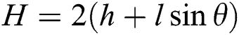 which are the specimen length on the X and Y directions, respectively. θ and t are fixed and the other parameters (l and h) can be determined from the values of L and H.
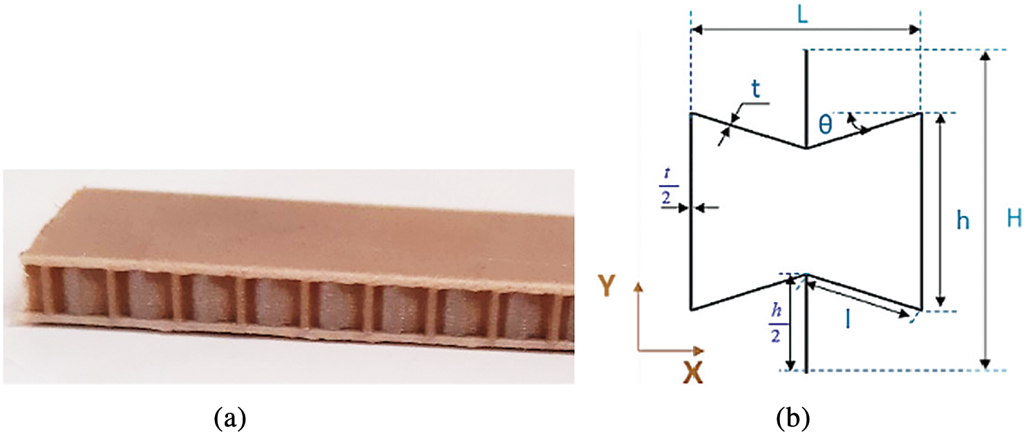
Figure 1: a) Sandwich structure with re-entrant honeycomb cores and b) design of unit cell of auxetic structure. Adapted with permission from [6], Copyright © 2020, Composites Part A: Applied Science and Manufacturing
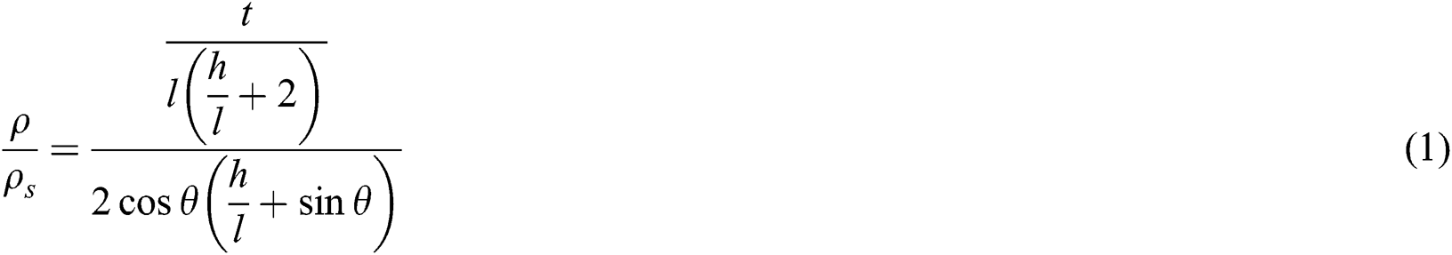
Each cell number width results in a specific core density. Therefore, 4 core densities are proposed in this study. The relative density [24,38], which is the ratio between the density of auxetic cells (ρ) and material density (ρs), can be calculated as Eq. (1):
Tab. 1 present the dimensions of the auxetic unit cell used in the core and the relative densities of each configuration. The material properties are measured using uniaxial tensile testing performed on 3D printed dog-bone following the ASTM D638 standard. The values obtained are presented in Tab. 2. The sandwich is set to be 25 mm wide and the thickness is equal to 7 mm (1 mm for each skin and 5 mm for the core). The length of the specimens tested is equal to 120 mm.
Table 1: Design parameters of auxetic core. Adapted with permission from Ref. [6], Copyright © 2020, Composites Part A: Applied Science and Manufacturing
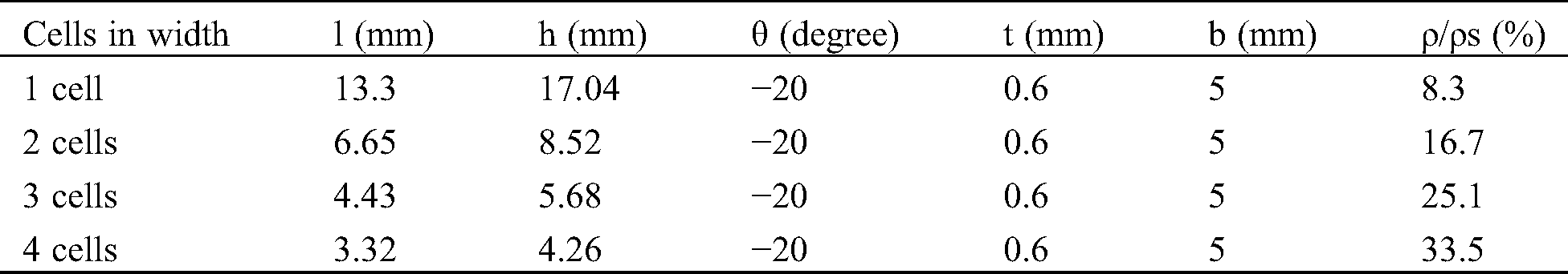
Table 2: Engineering constants of polylactic acid reinforced with flax fibers. Adapted with permission from Ref. [6], Copyright © 2020, Composites Part A: Applied Science and Manufacturing

The sandwich composites structures are manufactured with the 3D printing machine named MakerBot Replicator 2 Desktop. It is a machine dedicated to additive manufacturing. Fig. 2 presents the design of the 3D printing process. It consists of an extrusion head, filament rolls, building platform and X-Y motion mechanism. The travel speed is set to 100 mm/s, the extrusion temperature of 210°C, and the building platform temperature is equal to 55°C. These parameters are used according to a parametric study and chosen in the way that lead to the stability of specimens. The 3D printed sandwich composite is designed using CAD software, then translated into instructions compatible with the machine.
Printing orientation is taken into account due to the layer-by-layer fabrication course of 3D printing technology. The sandwiches were printed in three different orientations (X, Y and Z directions), as shown in Fig. 1a. It was found that X-printing orientation improve the mechanical properties of the sandwich material. Therefore, the same orientation is adopted to print all specimens (X-orientation).
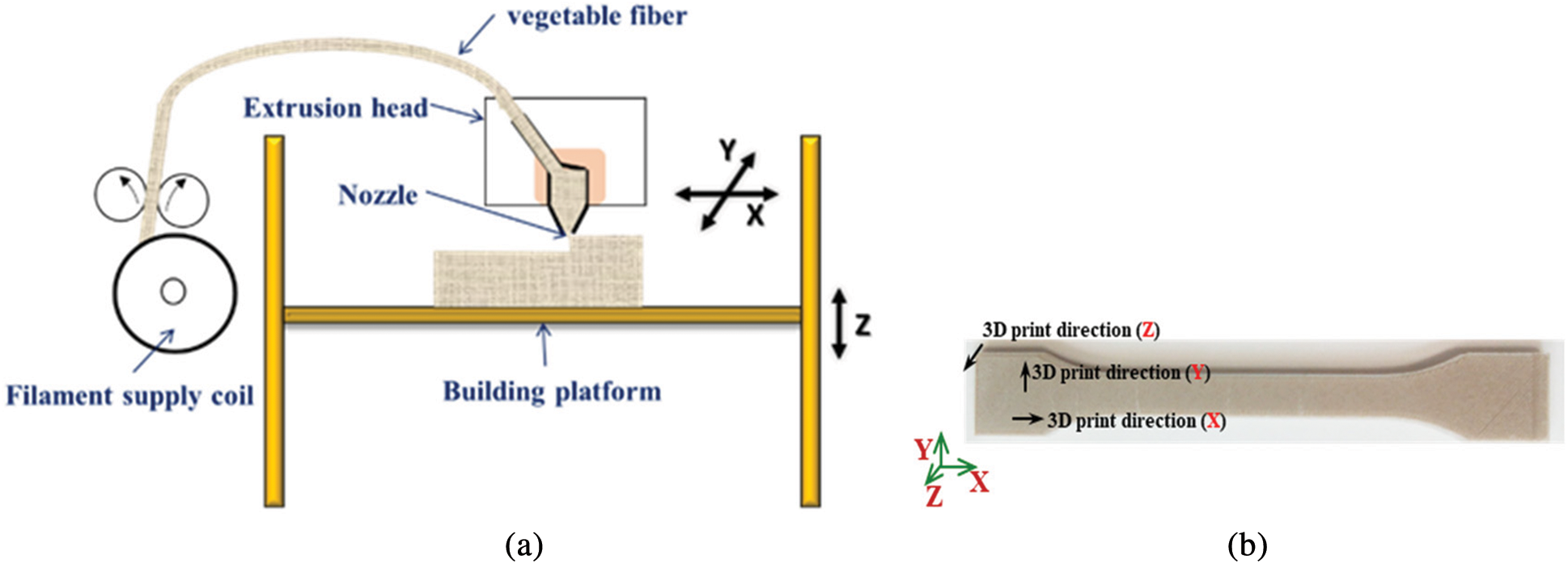
Figure 2: a) The design of 3D printing process, b) 3D printing direction
Experimental tests are performed on a standard hydraulic machine INSTRON 8801. The capacity of the machine is ±10 kN used for static and fatigue tests. The machine is equipped with load cells of 10 kN to measure the force and an LVDT sensor to measure the displacement. It is interfaced with a dedicated computer for monitoring and data acquisition. Three-point bending tests are carried out according to the ASTM D790-86 standard, as shown in Fig. 3. Tests are performed on 3D printed sandwiches with different core densities. At least five specimens per configuration are tested in order to take into account the variability of experimental results. The span length is set to 110 mm. In static tests, the sandwich beams are loaded at a displacement rate of 5 mm/min. The fatigue tests are performed using a load cell of 1 kN and sinusoidal type of waveform with a frequency of 5 Hz. Tests are carried out using a displacement control technique.
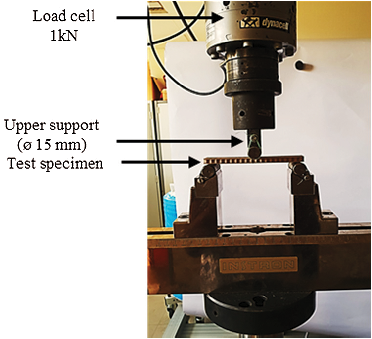
Figure 3: Three-point bending test set up. Adapted with permission from [6], Copyright © 2020, Composites Part A: Applied Science and Manufacturing
The specimens are tested with a span length of 110 mm. A loading ratio R, defined as follows: Eq. (2), is equal to 0.2:

where dmin and dmax are the minimum and the maximum displacements applied during the cycle, respectively. The average displacement dmean and the amplitude of displacement damp are then varied in order to diversify the loading level r defined by Eq. (3):

where drup is the failure displacement under quasi-static three-point bending tests. At least two specimens per loading configuration are tested in order to take into account the variability of experimental results. Two different loading levels are tested (r = 0.5 and r = 0.8).
Fig. 4 represents typical load-deflection curves obtained from sandwich specimens with different core densities. For each configuration, three regions are observed. Initially, a linear part that presents the linear behaviour of the sandwich is detected. The load and deflection of sandwiches with higher core densities at the limit of this linear part are higher than those with lower core densities. The second region represents the nonlinear behaviour of the sandwiches. It corresponds to the compressive behaviour of the core due to the bending of the top skin. It depends especially on the core properties and configurations. Damage initiation is detected in this region. Finally, the third region represents the failure of the sandwiches. With each load increase, the damage increases proportionally in the specimens until failure. Considering the deflection of the specimens at failure, it can be seen that sandwiches with a high core density have the largest bending deflection and the highest loading forces and stiffness.
Recently, the bending behaviour have been employed for 3D printed sandwich composite with different core topology out of PLA polymer [39]. Results show that the core topology has a significant role on the load-deflection curves. It is also found that sandwich with auxetic core has much lower flexural modulus and stress level at the same deformation level compared to cubic, Isomax and octet meta-sandwich.
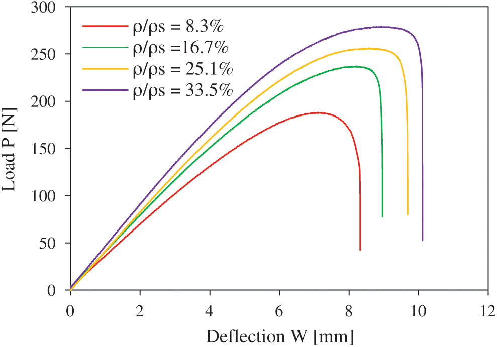
Figure 4: Bending characteristic of sandwich beams with different relative core densities
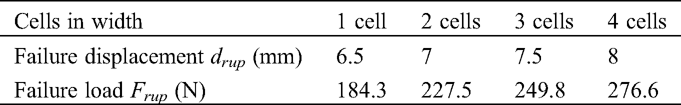
In the case of fatigue tests with displacement control, the value of ultimate failure displacement is needed to define the loading level. An average displacement dmean is determined. Around this value, a cyclic displacement with an amplitude of damp is applied. To avoid applying the loading level simultaneously in the two linear and nonlinear domains, the ultimate displacement is taken from the limit of the linear domain. Values for drup (ultimate failure displacement) and Frup (ultimate failure load) for each sandwich configuration are given in Tab. 3.
Table 3: Design parameters of auxetic core
The fatigue bending behaviour of the sandwich structure with different core densities is investigated. The changes in stiffness evolution under cyclic loading conditions, according to the number of cycles are recorded. This method is one of the commonly used approaches to study damage propagation during fatigue. Fig. 5 shows the evolution of the maximum applied load F, with the number of cycles, normalized by the initial maximum load F0. The stiffness loss (F/F0) is studied for two loading levels (r = 50% and r = 80%) using a semi-logarithmic scale. For each configuration, the results obtained show that the stiffness loss up to failure can be divided in three phases. In the first few cycles, a reduction in stiffness appears which corresponds to the initial degradation of the mechanical properties of the sandwich structure. It conditions the damage initiation and the cracking multiplication of the specimens. The second phase corresponds a very slow reduction in stiffness. It corresponds to the quasi-totality of the life of the beams. This cracking is rather quickly initiated in sandwiches with high loading level r. Finally, during the third phase, a sudden decrease in stiffness is observed. The damage mechanism proceeds with the increase in the number of cycles. This phase represents the total failure of the specimens. For a high loading level, the sandwich beams present a higher degradation rate and fail earlier than those with the lower ones.
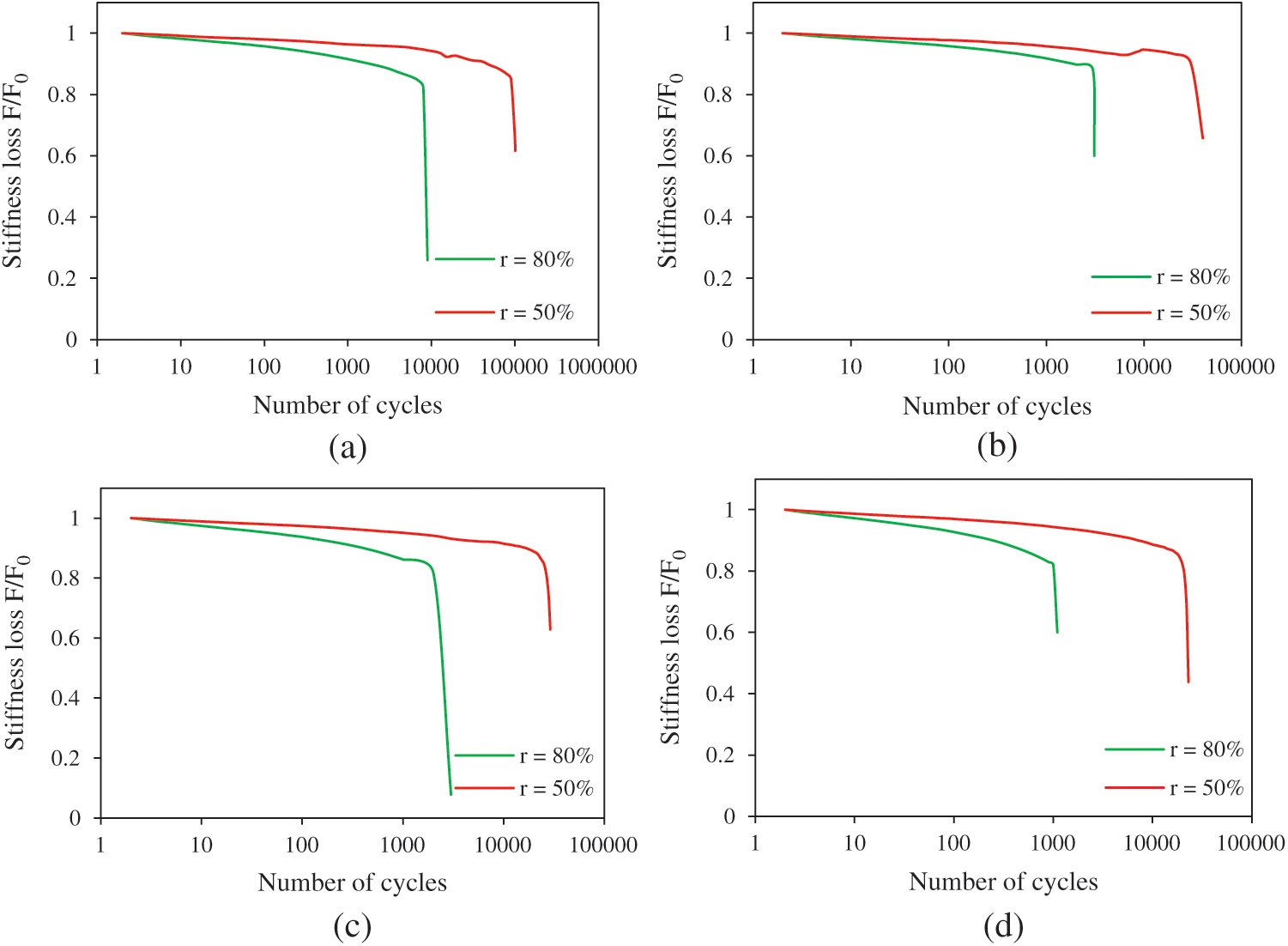
Figure 5: Stiffness loss vs. the number of cycles for various loading levels of sandwiches with different relative core densities: a) 8.3%; b) 16.7%; c) 25.1% and d) 33.5%
In order to better explain the effect of core density on the stiffness under cyclic fatigue tests, the maximum load of different configurations is presented in Fig. 6. The results are plotted using a semi-logarithmic scale. These curves are plotted for the same loading level of 80% and with the same loading ratio R of 0.2. It can be observed in this figure that the maximum load decreases with the number of cycles and with the decrease in core density. The rate of stiffness degradation depends on the density of the auxetic core. It can be seen that the stiffness reduction rate for the four-sandwich configuration is almost the same, up to failure. For higher densities, the stiffness reduction rate becomes quite evident and shows a marked difference, as we see for the sandwich with a 33.5% core density. An increase in the core density causes an increase in surface contact between the core and the skins. This causes an increase in surface shear stress transfer between the skin and the core. That’s why the stiffness reduction rate is more remarkable for this configuration. During the first cycles, the sandwich with a relative core density of 33.5% has a maximum load of 290 N and for the sandwich with a relative core density of 8.3% the maximum load is 175 N. The failure of the sandwich structure with higher core density is earlier than that with the lower core density.
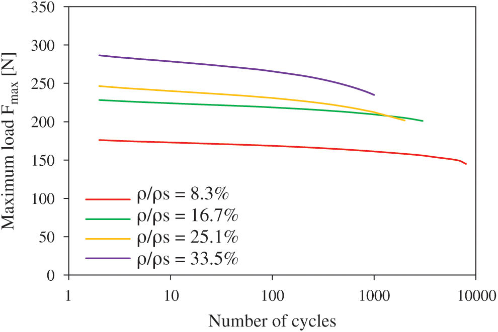
Figure 6: Evolution of the maximum load vs. the number of cycles for a loading level r = 80% of the sandwich composite with different relative core densities
For each configuration, the energy characteristics during fatigue tests are studied by analyzing the evolution of hysteresis curves. The loading level is fixed at 80%. Every cycle is defined by 200 experimental points. Fig. 7 presents the experimental load-displacement curves for loading and unloading cycles at 10, 100, 500 and 1000 cycles for sandwiches with different core densities. The curves are not very clear, congestion is clearly seen. Therefore, the curves are translated along the displacement axis for each cycle. The behaviour of hysteresis curves is similar for the four sandwich configurations.
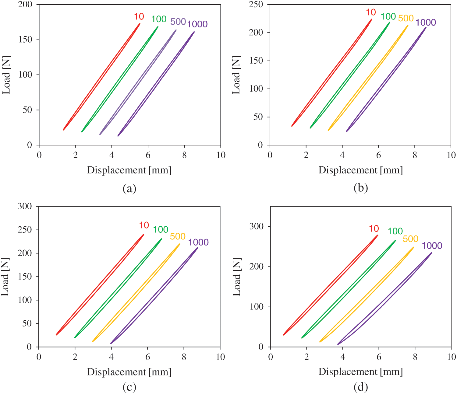
Figure 7: Hysteresis curves for different number of cycles for a loading level r = 80% of the sandwich with different relative core densities: a) 8.3%; b) 16.7%; c) 25.1% and d) 33.5%
On the other hand, the peak loads are different for each sandwich. It is clearly seen that the peak load increases with the increase in the density of the auxetic core. With the increase in the number of cycles, the area under the hysteresis loops decreases. Also, for the first cycles, the peak loads are higher than those of the last cycles. The decrease in the maximum load loop is the greatest for the sandwich with a relative core density of 33.5%. This decrease can be explained by the stiffness loss and damage development in the sandwich, which is governed by the degradation of the unit cells forming the auxetic core. The increase in the number of cycles causes a distortion of the hysteresis curve. The distortion becomes great at 1000 cycles and with a relative core density of 33.5%. It can be concluded from this result that the dynamic response of a sandwich with auxetic core subject to loading is not the same as its response to unloading. Total breaks appear at 9000, 4000, 3000 and 2000 cycles for the sandwiches with relative core densities of 8.3%, 16.7%, 25.1% and 33.5%, respectively. Due to cyclic loading, the cell walls of the auxetic core are totally collapsed. That’s why for the higher cycle’s numbers, a decrease in the peak load is not possible. The total rupture of the unit cells and the fracture of cell edges leads to the appearance of an irreversible damage in the sandwich followed by failure.
In this context, Bezazi et al. [40] have shown that auxetic foams are more sensible to compressive fatigue than the conventional and the iso-density ones. This behaviour can be further evidenced by the energy loss associated with the hysteresis cycles. The auxetic foam shows a significantly higher hysteresis cycle compared to the conventional and iso-density foams.
Fatigue experimental tests are used to quantify the energy dissipation capacity of sandwich composites with auxetic cores under different loading levels. Auxetic structures have shown their excellent ability to absorb energy. They dissipate the greatest amount of energy when they are used as the core of sandwich undergoing impact or indentation tests. In this study, sandwich specimens are tested in three-point bending in cyclic fatigue. Considering the hysteresis cycle illustrated in Fig. 7, the area enclosed by the hysteresis loops presents the dissipated energy Ed for each cycle. The load-displacement behaviour of the sandwiches depends on strain energy. The potential energy stored Ep is the area under the upper part (loading part) of the hysteresis loop. Using a trapezoidal summation of the area as shown in Fig. 8, dissipated energy Ed and maximum potential energy Ep are determined.
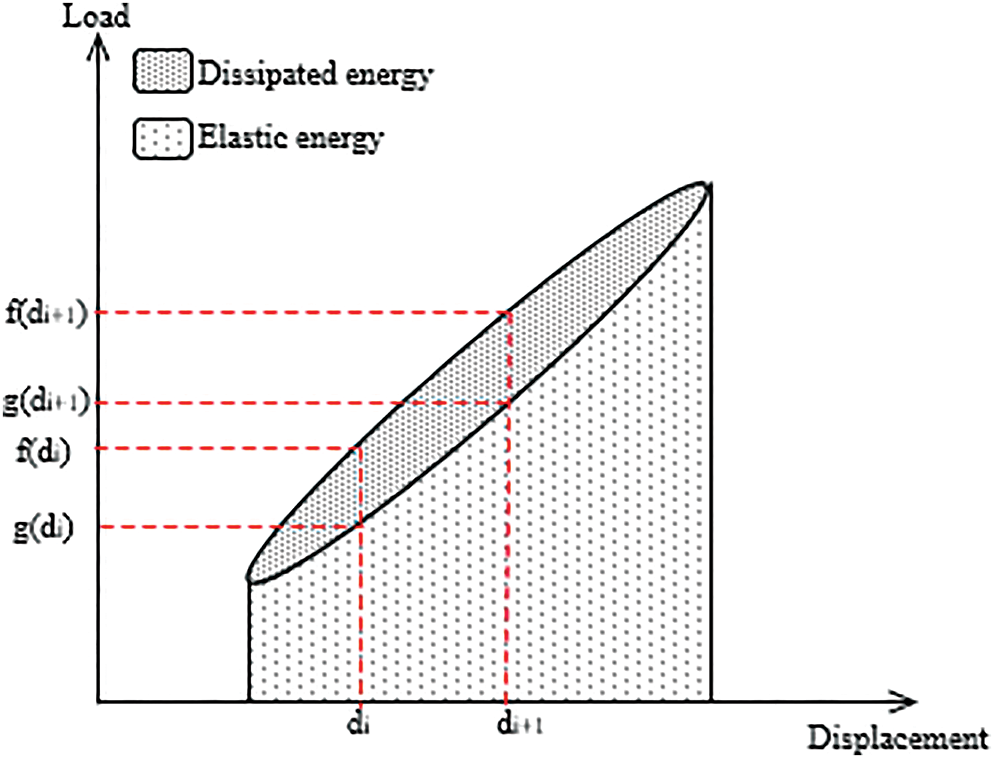
Figure 8: Illustration of a hysteresis cycle
To reduce calculated area error, the hysteresis curves are divided by a large number n. The dissipated and potential energy are given by Eqs. (4) and (5) [41]:


The energy dissipated according to the number of cycles for different loading levels (r = 50% and r = 80%) is given in Fig. 9. These figures present a comparison of the energy dissipated for sandwich composites with different core densities. The curves represent the quantity of energy dissipated by the structures during their operation, which provides an insight on the lifetime of the material. Sandwiches with a high auxetic core density dissipate more energy than those with low core density. High auxetic core densities dissipate more energy with the increase in the number of cycles.
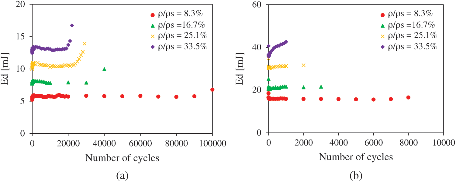
Figure 9: Energy dissipation vs. number of cycles in sandwich specimens with different relative core densities for different loading levels: a) r = 50%; b) r = 80%
During the first cycles, the energy dissipated is practically constant. Afterwards, it increases for a higher number of cycles. For both 8.3% and 16.7% relative core density, the sandwich with loading level r = 50% presents a significant difference in terms of energy loss per unit volume. It is interesting to note that the response to fatigue exhibits greater changes from the initial part of fatigue life to the end of life. This is due to the increasing of damage in the sandwich during fatigue tests. Also, the air present in the auxetic cells plays an important role in the dissipation of energy during fatigue. During the loading and unloading of the auxetic structure, a large quantity of energy is dissipated by collapsing the cell walls. This explains the greater amount of energy dissipated by sandwiches with high core density since it presents a large number of cell walls. Also, there is a rapid decrease in air contribution. This can be explained by the appearance of damage in the auxetic core.
The re-entrant honeycomb sandwich composites are better potential candidates for energy absorption applications compared with conventional honeycomb and truss [38]. Due to the deformation mechanism, the specific energy absorption of the auxetic sandwich composites is not as large as several recently developed architecture materials, such as honeytube structures [42], hollow microtruss structures [43] and bicontinuous structures [44] which have proven to exhibit significantly higher specific energy absorption.
The energy dissipation in sandwich composites is affected by different parameters such as the topology of the core and the viscoelastic behaviour of material constituting the core and the skins. The loss factor in cyclic fatigue tests is defined as the ratio of the energy dissipated per cycle Ed by the maximum potential energy per cycle Ep. Thus, the loss factor is given by Eq. (6):

Fig. 10 shows the evolution of the fatigue loss factor ƞ for the sandwich structure tested with a span length of 110 mm and for two different loading levels (r = 50% and r = 80%). A semi-logarithmic scale is used. It is clearly seen that the loss factor decreases with the increase in the applied loading ratio and increases with the number of cycles. During the first cycles, a rapid decrease can be observed whatever the loading configuration. This result can be explained by the first damage mechanisms in the core caused by the first load applied to the sandwich. Then, an increase is detected during the first thousand cycles. Due to the appearance and propagation of damage, part of the air trapped in the unit cells is evacuated and no longer contributes to overall damping. Finally, the evolution in the loss factor becomes stable for all sandwich configurations. At the end of the tests, an increase in the loss factor can be noticed. This increase starts earlier for higher loading levels followed by the end of life. The evolution of the loss factor in sandwich specimen for variable debonding lengths under fatigue tests is determined [22]. It is found that for a given debonding length, the loss factor is constant in the first cycles of fatigue because the deformation of cells at the interface skin–core is a reversible manner. Then the loss factor increases with the number of fatigue cycles because the walls of damaged cells start allowing evacuation of the air trapped inside the cells.
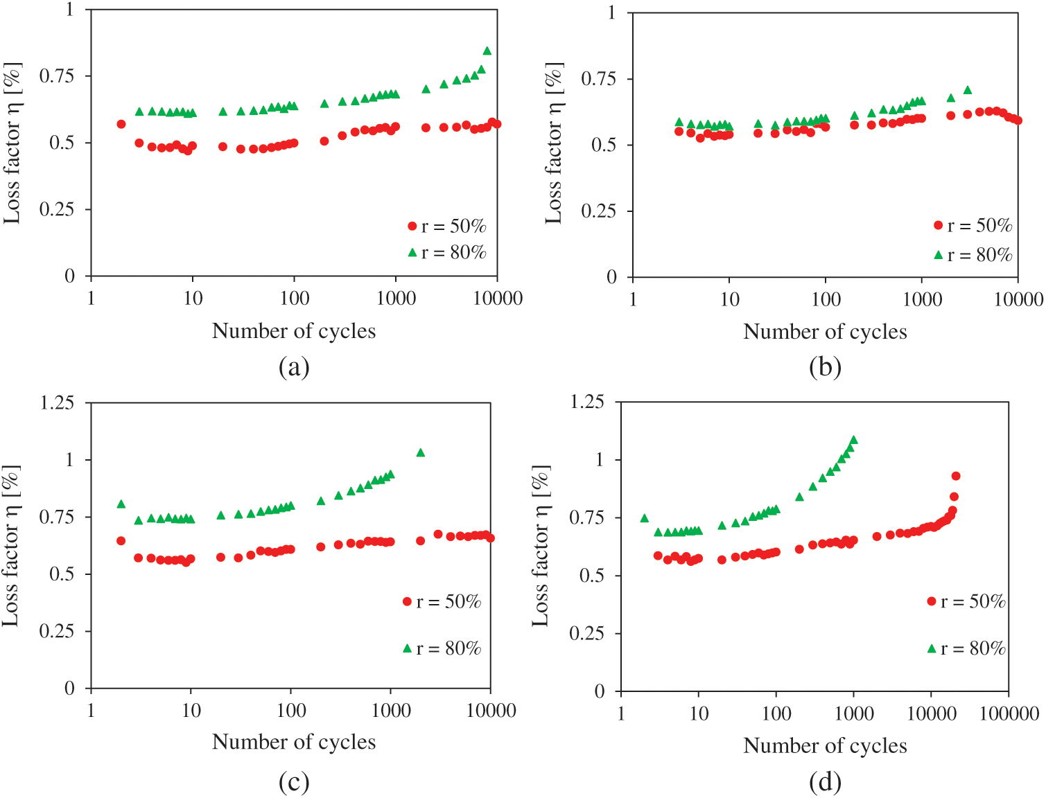
Figure 10: Evolution of loss factor vs. number of cycles for different loading level (r = 50% and r = 80%) of the sandwich with different relative core densities: a) 8.3%; b) 16.7%; c) 25.1% and d) 33.5%
In order to better explain the effect of the core density on the damping properties of the sandwich, it is decided to present the loss factor as a function of the core densities. Fig. 11 presents the evolution of the loss factor vs. the density of the auxetic core at different numbers of cycles (10, 100, 500 and 1000 cycles). The damping increases with the increase in the density of the core of the sandwich specimens. In the case of a loading level of 50% (Fig. 11a), the value of the damping ratio increases from 0.57% to 0.68% for an increase in the density of the auxetic structure from 8.3% to 33.5%. In Fig. 11b, the loss factor decreases at 16.7% relative core density. Then, damping increases for the other densities. The density of the core plays an important role in the damping properties, resistance and the life of sandwich composites.
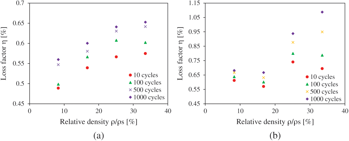
Figure 11: Evolution of loss factor vs. relative core density at different numbers of cycles for different loading levels: a) r = 50%; b) r = 80%
Studying and investigating the damage evolution and failure mechanisms under cyclic bending tests have proved to be a crucial matter. Numerous parameters influence the failure response of the sandwich structure, among them, the constituting material, the shape of the auxetic structure, the nature of the loading and its direction [41]. In this frame of reference, macroscopic and microscopic analyzes are conducted on the sandwich structure after the failure. Scanning electronic microscopy (SEM) is utilized to investigate the mechanisms resulting in damage.
The failure mechanisms of 3D printed sandwiches with diverse core topology and density under bending test is explored [39]. Core buckling is observed in cubic and auxetic sandwich beams, while core shear failure develops in octet meta-sandwich beams and a mix of core buckling and core fracture develops in Isomax meta-sandwich beams. The failure profile of the specimen is shown in Fig. 12. During the initial fatigue loading, the bottom skin endures the first cracking. The resulting fissure is responsible for the stiffness decrease during the initial cycles. It is the result of the breaking of the layers stashed by the 3D printing amid the construction of the sandwiches. Eventually, a local progressive decohesion between the bottom skin and the core interface is exhibited. It serves as an indicator to the very slow decrease in stiffness. Thus, the crack proliferates the core of the sandwich and local debonding show up in between the skin and the auxetic core. It is crucial to mention that opposed to traditional sandwich composites, 3D printed sandwich structures do not necessitate adhesion between the skins and core, which completely decreases the debonding chance of the core and skins [45]. SEM allows us to closely detect the property damage of the material at the microscopic scale. It provides an insight on the exact defect in the material. The fracture morphologies presented previously are also investigated under compressive loading for 3D printed structure [46].
The failure mechanisms of 3D printed sandwiches with different core topology and density under bending tests have been looked into [39]. Core buckling is detected in cubic and auxetic sandwich beams, while core shear failure take place in octet meta-sandwich beams and a mix of core buckling and core fracture develop in Isomax meta-sandwich beams.
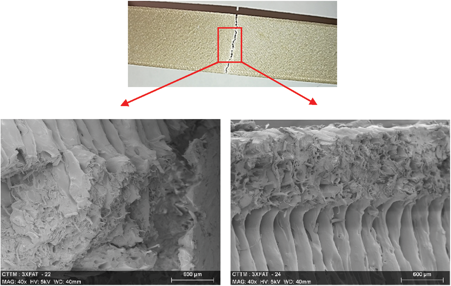
Figure 12: Macroscopic and SEM observations of failure profiles of the sandwich composite after fatigue failure
The assessment of the static and dynamic bending characteristics of bio-based sandwich composites with an auxetic core is discussed in this paper. The skins and core are produced from the same bio-based materials that is a tape of PLA strengthened with flax fiber (<20%). The topology of the core is drafted with CAD software and manufactured using 3D printing technology. To determine the structural responses and failure mechanisms, numerous dynamic tests were conducted on different core densities (4) with two loading levels.
Results have proven that the core density and the loading levels have a serious effect on the stiffness, energy dissipation and loss factor of the sandwich structures. Change in stiffness offers a satisfactory measure of the well-being of the sandwich specimens. Furthermore, it’s advised to use the loss factor in the evaluation of damage propagation in sandwich materials, which appears to be more significant than stiffness. Deriving out of the damage propagation mechanisms, it was noticed that the main culprit responsible for the stiffness decrease during fatigue is indeed the cracking of the bottom skin. Sandwiches with high core density showcased important energy dissipation in comparison to other configurations. Moreover, the damage mechanisms are established using SEM. Taking into consideration experimental tests, including a damage tracking approach with the help of acoustic emission technique (non-destructive method), might perhaps facilitate precise monitoring of the damage initiation and the affiliation between damage propagation and damping ratio evolution.
Funding Statement: The author(s) received no specific funding for this study.
Conflicts of Interest: The authors declare that they have no conflicts of interest to report regarding the present study.
1. Jiang, L., Walczyk, D., McIntyre, G., Bucinell, R., Li, B. (2019). Bioresin infused then cured mycelium−based sandwich−structure biocomposites: Resin transfer molding (RTM) process, flexural properties, and simulation. Journal of Cleaner Production, 207, 123–135. DOI 10.1016/j.jclepro.2018.09.255. [Google Scholar] [CrossRef]
2. Jiang, L., Walczyk, D., McIntyre, G., Bucinell, R., Tudryn, G. (2017). Manufacturing of biocomposite sandwich structures using mycelium-bound cores and preforms. Journal of Manufacturing Processes, 28, 50–59. DOI 10.1016/j.jmapro.2017.04.029. [Google Scholar] [CrossRef]
3. Lee, J. M., Yeong, W. Y. (2016). Design and printing strategies in 3D bioprinting of cell-hydrogels: A review. Advanced Healthcare Materials, 5(22), 2856–2865. DOI 10.1002/adhm.201600435. [Google Scholar] [CrossRef]
4. Sing, S. L., An, J., Yeong, W. Y., Wiria, F. E. (2016). Laser and electron-beam powder-bed additive manufacturing of metallic implants: A review on processes, materials and designs. Journal of Orthopaedic Research, 34(3), 369–385. DOI 10.1002/jor.23075. [Google Scholar] [CrossRef]
5. Tan, W. S., Chua, C. K., Chong, T. H., Fane, A. G., Jia, A. (2016). 3D printing by selective laser sintering of polypropylene feed channel spacers for spiral wound membrane modules for the water industry. Virtual and Physical Prototyping, 11(3), 151–158. DOI 10.1080/17452759.2016.1211925. [Google Scholar] [CrossRef]
6. Essassi, K., Rebiere, J. L., El Mahi, A., Ben Souf, M. A. Bouguecha, A. et al. (2020). Experimental and analytical investigation of the bending behaviour of 3D-printed bio-based sandwich structures composites with auxetic core under cyclic fatigue tests. Composites Part A: Applied Science and Manufacturing, 131, 105775. DOI 10.1016/j.compositesa.2020.105775. [Google Scholar] [CrossRef]
7. Joshi, S. C., Sheikh, A. A. (2015). 3D printing in aerospace and its long-term sustainability. Virtual and Physical Prototyping, 10(4), 175–185. DOI 10.1080/17452759.2015.1111519. [Google Scholar] [CrossRef]
8. Goh, G. D., Agarwala, S., Goh, G. L., Dikshit, V., Sing, S. L. et al. (2017). Additive manufacturing in unmanned aerial vehicles (UAVsChallenges and potential. Aerospace Science and Technology, 63, 140–151. DOI 10.1016/j.ast.2016.12.019. [Google Scholar] [CrossRef]
9. Dikshit, V., Yap, Y. L., Goh, G. D., Yang, H., Lim, J. C. et al. (2016). Investigation of out of plane compressive strength of 3D printed sandwich composites. IOP Conference Series: Materials Science and Engineering, 139(1), 012017. DOI 10.1088/1757-899X/139/1/012017. [Google Scholar] [CrossRef]
10. Soltani, A., Noroozi, R., Bodaghi, M., Zolfagharian, A., Hedayati, R. (2020). 3D printing on-water sports boards with bio-inspired core designs. Polymers, 12(1), 250. DOI 10.3390/polym12010250. [Google Scholar] [CrossRef]
11. Lu, L., Sharf, A., Zhao, H., Wei, Y., Fan, Q. et al. (2014). Build-to-last: Strength to weight 3D printed objects. ACM Transactions on Graphics (TOG), 33(4), 1–10. [Google Scholar]
12. Dikshit, V., Nagalingam, A. P., Yap, Y. L., Sing, S. L., Yeong, W. Y. et al. (2017). Investigation of quasi-static indentation response of inkjet printed sandwich structures under various indenter geometries. Materials, 10(3), 290. DOI 10.3390/ma10030290. [Google Scholar] [CrossRef]
13. Yan, L., Kasal, B., Huang, L. (2016). A review of recent research on the use of cellulosic fibres, their fibre fabric reinforced cementitious, geo-polymer and polymer composites in civil engineering. Composites Part B: Engineering, 92, 94–132. DOI 10.1016/j.compositesb.2016.02.002. [Google Scholar] [CrossRef]
14. Stamboulis, A., Baillie, C. A., Peijs, T. (2001). Effects of environmental conditions on mechanical and physical properties of flax fibers. Composites Part A: Applied Science and Manufacturing, 32(8), 1105–1115. DOI 10.1016/S1359-835X(01)00032-X. [Google Scholar] [CrossRef]
15. Baghaei, B., Skrifvars, M., Berglin, L. (2013). Manufacture and characterisation of thermoplastic composites made from PLA/hemp co-wrapped hybrid yarn prepregs. Composites Part A: Applied Science and Manufacturing, 50, 93–101. DOI 10.1016/j.compositesa.2013.03.012. [Google Scholar] [CrossRef]
16. Essassi, K., Rebiere, J. L., Mahi, A. E., Ben Souf, M. A., Bouguecha, A. et al. (2019). Experimental and numerical analysis of the dynamic behavior of a bio-based sandwich with an auxetic core. Journal of Sandwich Structures & Materials. DOI 10.1177/1099636219851547. [Google Scholar] [CrossRef]
17. Yan, L., Chouw, N., Jayaraman, K. (2014). Flax fibre and its composites–A review. Composites Part B: Engineering, 56, 296–317. DOI 10.1016/j.compositesb.2013.08.014. [Google Scholar] [CrossRef]
18. Lefeuvre, A., Bourmaud, A., Morvan, C., Baley, C. (2014). Elementary flax fibre tensile properties: Correlation between stress-strain behaviour and fibre composition. Industrial Crops and Products, 52, 762–769. DOI 10.1016/j.indcrop.2013.11.043. [Google Scholar] [CrossRef]
19. Monti, A., El Mahi, A., Jendli, Z., Guillaumat, L. (2017). Experimental and finite elements analysis of the vibration behaviour of a bio-based composite sandwich beam. Composites Part B: Engineering, 110, 466–475. DOI 10.1016/j.compositesb.2016.11.045. [Google Scholar] [CrossRef]
20. Hajer, D., Jean-Luc, R., Charfeddin, M., Mohamed, T., Mohamed, H. (2018). Experimental analysis of the linear and nonlinear vibration behavior of flax fibre reinforced composites with an interleaved natural viscoelastic layer. Composites Part B: Engineering, 151, 201–214. DOI 10.1016/j.compositesb.2018.06.015. [Google Scholar] [CrossRef]
21. Monti, A., El Mahi, A., Jendli, Z., Guillaumat, L. (2019). Quasi-static and fatigue properties of a balsa cored sandwich structure with thermoplastic skins reinforced by flax fibres. Journal of Sandwich Structures & Materials, 21(7), 2358–2381. DOI 10.1177/1099636218760307. [Google Scholar] [CrossRef]
22. Idriss, M., El Mahi, A., Assarar, M., El Guerjouma, R. (2013). Damping analysis in cyclic fatigue loading of sandwich beams with debonding. Composites Part B: Engineering, 44(1), 597–603. DOI 10.1016/j.compositesb.2012.02.024. [Google Scholar] [CrossRef]
23. Allen, H. G. (1969). Analysis and design of structural sandwich panels. Pergamon, New York. [Google Scholar]
24. Gibson, L. J., Ashby, M. F. (1999). Cellular solids: Structure and properties. Cambridge university press, UK. [Google Scholar]
25. Bezazi, A., Scarpa, F. (2009). Tensile fatigue of conventional and negative Poisson’s ratio open cell PU foams. International Journal of Fatigue, 31(3), 488–494. DOI 10.1016/j.ijfatigue.2008.05.005. [Google Scholar] [CrossRef]
26. Essassi, K., Rebiere, J. L., El Mahi, A., Ben Souf, M. A., Bouguecha, A. et al. (2019). Dynamic characterization of a bio-based sandwich with auxetic core: experimental and numerical study. International Journal of Applied Mechanics, 11(2), 1950016. DOI 10.1142/S1758825119500169. [Google Scholar] [CrossRef]
27. Bodaghi, M., Serjouei, A., Zolfagharian, A., Fotouhi, M., Rahman, H. et al. (2020). Reversible energy absorbing meta-sandwiches by FDM 4D printing. International Journal of Mechanical Sciences, 173, 105451. DOI 10.1016/j.ijmecsci.2020.105451. [Google Scholar] [CrossRef]
28. Bodaghi, M., Liao, W. H. (2019). 4D printed tunable mechanical metamaterials with shape memory operations. Smart Materials and Structures, 28(4), 045019. DOI 10.1088/1361-665X/ab0b6b. [Google Scholar] [CrossRef]
29. Huang, J. S., Liu, S. Y. (2001). Fatigue of honeycombs under in-plane multiaxial loads. Materials Science and Engineering: A, 308(1–2), 45–52. DOI 10.1016/S0921-5093(00)01996-1. [Google Scholar] [CrossRef]
30. Zhang, D., Fei, Q., Zhang, P. (2017). Drop-weight impact behavior of honeycomb sandwich panels under a spherical impactor. Composite Structures, 168, 633–645. DOI 10.1016/j.compstruct.2017.02.053. [Google Scholar] [CrossRef]
31. Crupi, V., Epasto, G., Guglielmino, E. (2012). Collapse modes in aluminium honeycomb sandwich panels under bending and impact loading. International Journal of Impact Engineering, 43, 6–15. DOI 10.1016/j.ijimpeng.2011.12.002. [Google Scholar] [CrossRef]
32. Lu, J. (2011). Investigation on fatigue behavior of metallic honeycomb sandwich structures. Journal of Harbin Engineering University, 184. [Google Scholar]
33. Evans, A. G., He, M., Deshpande, V. S., Hutchinson, J. W., Jacobsen, A. J. et al. (2010). Concepts for enhanced energy absorption using hollow micro-lattices. International Journal of Impact Engineering, 37(9), 947–959. DOI 10.1016/j.ijimpeng.2010.03.007. [Google Scholar] [CrossRef]
34. Li, M. Z., Stephani, G., Kang, K. J. (2011). New cellular metals with enhanced energy absorption: Wire-woven bulk Kagome (WBK)-metal hollow sphere (MHS) hybrids. Advanced Engineering Materials, 13(1–2), 33–37. DOI 10.1002/adem.201000165. [Google Scholar] [CrossRef]
35. Altan, G., Kovan, V. (2016). Flexural behavior of 3D printed honeycomb sandwich structures with waste filler material. Materials Testing, 58(10), 833–838. DOI 10.3139/120.110927. [Google Scholar] [CrossRef]
36. Berger, J. B., Wadley, H. N. G., McMeeking, R. M. (2017). Mechanical metamaterials at the theoretical limit of isotropic elastic stiffness. Nature, 543(7646), 533–537. DOI 10.1038/nature21075. [Google Scholar] [CrossRef]
37. Essassi, K., Rebiere, J. L., El Mahi, A., Ben Souf, M. A., Bouguecha, A. et al. (2020). Investigation of the static behavior and failure mechanisms of a 3D printed bio-based sandwich with auxetic core. International Journal of Applied Mechanics, 12(5), 2050051. DOI 10.1142/S1758825120500519. [Google Scholar] [CrossRef]
38. Li, T., Wang, L. (2017). Bending behavior of sandwich composite structures with tunable 3D-printed core materials. Composite Structures, 175, 46–57. DOI 10.1016/j.compstruct.2017.05.001. [Google Scholar] [CrossRef]
39. Sarvestani, H. Y., Akbarzadeh, A. H., Mirbolghasemi, A., Hermenean, K. (2018). 3D printed meta-sandwich structures: Failure mechanism, energy absorption and multi-hit capability. Materials & Design, 160, 179–193. DOI 10.1016/j.matdes.2018.08.061. [Google Scholar] [CrossRef]
40. Bezazi, A., Scarpa, F. (2007). Mechanical behaviour of conventional and negative Poisson’s ratio thermoplastic polyurethane foams under compressive cyclic loading. International Journal of Fatigue, 29(5), 922–930. DOI 10.1016/j.ijfatigue.2006.07.015. [Google Scholar] [CrossRef]
41. Alomarah, A., Masood, S. H., Sbarski, I., Faisal, B., Gao, Z. et al. (2020). Compressive properties of 3D printed auxetic structures: Experimental and numerical studies. Virtual and Physical Prototyping, 15(1), 1–21. DOI 10.1080/17452759.2019.1644184. [Google Scholar] [CrossRef]
42. Yin, S., Li, J., Liu, B., Meng, K., Huan, Y. et al. (2017). Honeytubes: Hollow lattice truss reinforced honeycombs for crushing protection. Composite Structures, 160, 1147–1154. DOI 10.1016/j.compstruct.2016.11.007. [Google Scholar] [CrossRef]
43. Liu, Y., Schaedler, T. A., Chen, X. (2014). Dynamic energy absorption characteristics of hollow microlattice structures. Mechanics of Materials, 77, 1–13. DOI 10.1016/j.mechmat.2014.06.008. [Google Scholar] [CrossRef]
44. Lee, J. H., Wang, L., Boyce, M. C., Thomas, E. L. (2012). Periodic bicontinuous composites for high specific energy absorption. Nano Letters, 12(8), 4392–4396. DOI 10.1021/nl302234f. [Google Scholar] [CrossRef]
45. Schaedler, T. A., Carter, W. B. (2016). Architected cellular materials. Annual Review of Materials Research, 46(1), 187–210. DOI 10.1146/annurev-matsci-070115-031624. [Google Scholar] [CrossRef]
46. Yang, J., Gu, D., Lin, K., Ma, C., Wang, R. et al. (2020). Laser 3D printed bio-inspired impact resistant structure: Failure mechanism under compressive loading. Virtual and Physical Prototyping, 15(1), 75–86. DOI 10.1080/17452759.2019.1677124. [Google Scholar] [CrossRef]
 | This work is licensed under a Creative Commons Attribution 4.0 International License,, which permits unrestricted use, distribution, and reproduction in any medium, provided the original work is properly cited. |