DOI: 10.32604/jrm.2021.014310
ARTICLE
The Micro-Scale Mechanism of Metal Mine Tailings Thickening Concentration Improved by Shearing in Gravity Thickener
1International Joint Research Laboratory of Henan Province for Underground Space Development and Disaster Prevention, Henan Polytechnic University, Jiaozuo, 454000, China
2College of Safety Science and Engineering, Henan Polytechnic University, Jiaozuo, 454000, China
3Civil and Resource Engineering School, University of Science and Technology Beijing, Beijing, 100000, China
4No.11 Coal Mine of Pingdingshan Tianan Coal Mining Co., Ltd., Pingdingshan, 467000, China
*Corresponding Author: Wei Wang. Email: wangwei@hpu.edu.cn
Received: 17 September 2020; Accepted: 21 October 2020
Abstract: Higher concentration is beneficial for the Paste and Thickened Tailings (PTT) operation in metal mine. Partial paste thickeners are produced lower density underflow. Flocculated tailings are intended to form a water entrapped network structure in thickener, which is detrimental to underflow concentration. In this study, the continuous thickening experiment was carried out for ultra-fine tungsten tailings to study the influence of rake shearing on underflow. The micro pores structure and seepage flow in tailings bed before and after shearing are studied by CT and simulation approach to reveal the shearing enhancement mechanism of thickening process. The results shown that, the underflow concentration is increased from 61.4 wt% to 69.6 wt% by rake shearing in a pilot scale thickener, the porosity decreased from 46.48% to 37.46%. The entrapped water discharged from sticks structure more than sphere spaces. In items of seepage, after shearing, the seepage flow channel of tailings underflow is becoming longer, which caused the decreasing average flow rate decreases and absolute permeability. The absolute permeability is negatively correlated with tortuosity. The rake shearing can destroy the flocs structure; change the effective stress to increase the concentration. Higher underflow concentration improves the waste recycling and water recovery rate, especially for arid areas.
Keywords: Metal mine tailings; gravity thickening; shearing effect; pore microstructure; reverse direction seepage; flow channel
The metal minerals processing industry produces million tons of fluidized tailings annually [1,2]. The mining tailings stream from plant, typically contain clays, silts, sand, and residual ore, is in form of low concentration slurry. Among them, up to 90% tailings are treated by the traditional low concentration disposal approach [3,4], which would like to cause dams failure and acid water leakage risk [5,6]. The Paste and Thickened Tailings (PTT) technology has been widely adopted in operations of metal mine tailings disposal, cemented paste backfills [7,8], solids waste recycling [9,10], and water recovery [11]. The polymer flocculants were widely used to facilitate the solids liquid separation velocity in tailings gravity thickening processes [12,13]. However, in aspects of PTT technology, emphasis is placed on the enhanced dewatering of the flocculated tailings bed, rather than the rapid settlement. The effective consolidation of fine particles are major challenges.
The gel-like tailings flocs produced by polyacrylamides entrapped water inside the honeycomb network structure [14,15]. Therefore, the gravity thickening underflow concentration of fine tailings (copper mine tailings) is generally lower than 65%. Unfortunately, PTT technology generally requires that, the underflow concentration is higher than 65 wt%, with a yield stress higher than 100Pa [16]. The structure and the entrapped water would determine the flocs consolidation degree [17]. The flocculated tailings flocs are highly porous, which require further compaction to release the entrapped water. The entrapped water quantity is directly influenced by the flocculation rate and flocs size [18,19]. New alternatives flocculants have been published to generate a denser flocs structure by modify the inter-particle bridging and flocculation circumstance, which for improving the tailings bed consolidation efficiency [20−22].
Furthermore, the flocs compaction behavior upon shear is also a key factor to improve the raking thickener performance [23,24]. The flocs shape became more spherical with the shear rates, in addition to the changes of flocs size and structure after shearing [25,26]. The aggregates were able to restructure due to edge-edge associations between particles [27]. The shearing created a large quantity of small flocs from the tailings bed network structure. In addition, the flocs were reconstructed by rake shear due to the edge association changing between tailings particles.
The shearing lead to particles restructuring and reorganization of the flocs, the connection of pores structure can produce the channels for drainage water. The complex dewatering behavior is occurring through the flow channel [28]. However, there are few reports about the influence of shearing on the thickening suspension and flow channel of flocculated tailings [29]. The shearing effects on the relationship between the flocs structural changes and flocculants dose in thickened tailings slurry is not well characterized [30]. In addition, there is few literates focus on the relationship between the flocs size or structure and the flow channel in the sedimentation bed [31]. Jiao has identified the evolution of pore structure and throat before and after shearing by Pore network model (PNM) approach [32].
However, there appears to be no combined study of rake shearing and water seepage processes for high solids volume fraction flocculated tailings thickening bed. The process of flow channel formation, development and annihilation need to be further investigated. Meanwhile, visualization of floc microstructure is beneficial for the explanation of the interaction between the pore structure and the flow channel. This information observed in this study can, in turn, help in the water recovery, tailings waste recycling, heavy metals ions solidification, and underground cemented paste backfill operation.
2.1 Pilot-Scale Continuous Thickening Test
The dynamic shear test was carried out on a pilot-scale continuous thicker, as shown in Fig. 1(a), 1(b). The settling cylinder height is 50 cm, the diameter 10 cm, the height of rake with four pickets is 30 cm. The rake rotation speed is 2 revolutions per minute (rpm). The drive shaft with sensors can detect rotation speed and torque. The optimal experimental parameters were obtained by flocculants selection and indoor sedimentation experiments, an anionic polyacrylamide (APAM) with 20 million molecular weight was selected as flocculant at the dosage of 30g/t, dilution concentration of 0.01 wt%, and the feed tailings slurry concentration was 12 wt%. The feed was pumped into a T-pipe for mixing with flocculants dilution. The thickener has an underflow discharge pump and an overflow system.
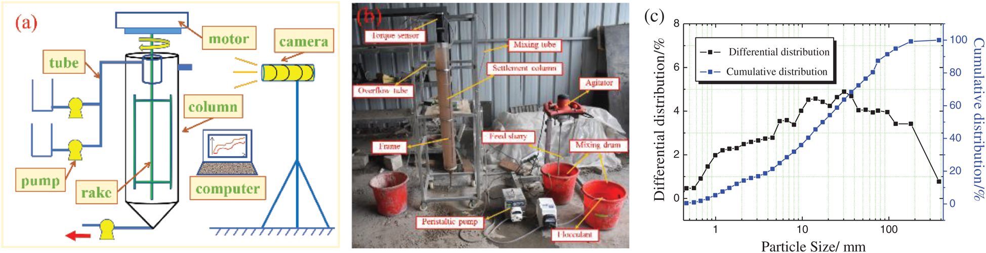
Figure 1: The pilot scale continuous thickening test (a) Schematic of thickener (b) Equipments layout (c) Tailings particle size distribution
The unclassified tailings were from Xianglushan Tungsten Mine in Jiangxi Province. The tailings were neutral to alkali, and high porosity. The physical parameters are shown in Tab. 1.
Table 1: Specific gravity, bulk density, porosity, natural angle of repose
The flotation tailings of tungsten ore are ultra-fine, which is difficult to be dewatered and thickened. The average particle diameter is less than 0.03 mm; more than 50% particles are finer than 0.019 mm; less than 10% particles larger than 0.074 mm is; less than 30% larger than 0.037 mm. The particle size distribution (PSD) is shown in Fig. 1(c).
The scanning device is a phoenix v high-precision industrial micro-CT scanning system (Fig. 2) with a maximum spatial resolution of 0.2 μm. The magnification in this study is 1000 times. The layer spacing of 5μm is one pixel. A 1 mm × 1 mm × 1 mm cubic body located in the middle of the model would be selected for study, which was to ensure the bed structure were not been disturbed.
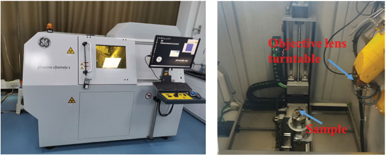
Figure 2: CT scanning equipment
The original CT image need to be de-noised [33,34]. The processes included the image enhancement, the image contrast increasing, the de-noising and the smoothing processing. Finally, the reconstructing to establish a model of three-dimensional contact relationship of tailings particles, as shown in Figs. 3(a), 3(b), 3(c). Furthermore, a visual pore network model (PNM), representing the true original microstructure appearance of tailings bed, is extracted from the 3D model, and the water flow channel is identified, as shown in Figs. 3(d), 3(e).
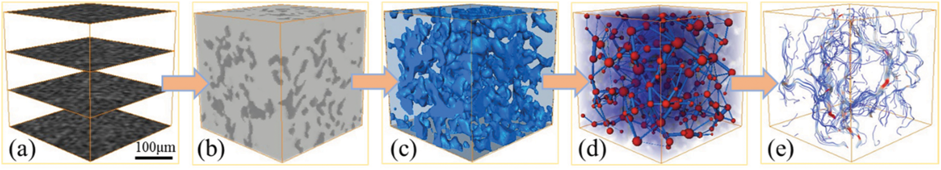
Figure 3: The 3D reconstruction processes (a) image enhancement (b) binarization (c) 3D reconstruction (d) pore network model (e) channel characterization
The Feret Diameter (FD) is used to measure the irregular pores and characterize the pore geometry [35]. The FD is defined as a point at the edge of the aperture, and the axis of rotation rotates in a clockwise direction. The spatial distance between another pixel point of the edge of the aperture and the origin, that is, the distance between the tangential parallel lines on the boundary of the aperture (Fig. 4).
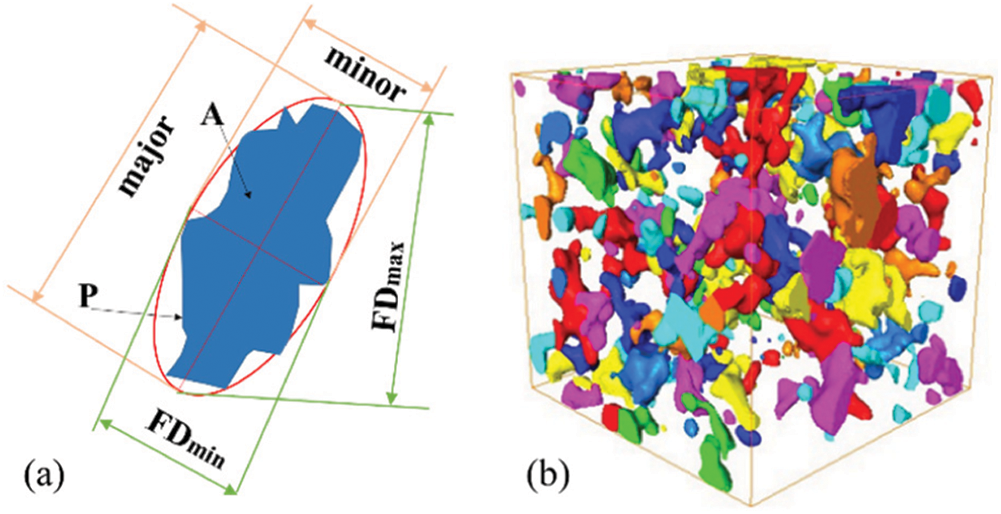
Figure 4: The pore geometry (a) Feret Diameter (b) detailed pore diagram
The pore geometry parameters are calculated by the pore contour perimeter P, μm, area A, μm2, Feret Diameter (FD), etc., where FDmax is the maximum length of single pore and FDmin is the maximum width of single pore, μm. The pores shape could be quantitatively analyzed by morphological parameters such as concavity (CV), roundness (RN) and Aspect Ratio (AR) [36].
The CV is a measure of the topological properties of particle projection, which is the ratio of the area of particle projection to the area of convex hull polygon. The CV can represent the smoothness of pore profile, follow the Eq. (1).

RN is a measure of the ratio of the particle’s projected area to the area of a circle with a diameter equal to the longest dimension, reflecting the extent to which the aperture is nearly circular. RN reflects the degree of pores close to the circle, follow the Eq. (2).

The AR is the maximum ratio between the length and width of a bounding box. AR represents the overall ductility of the pore, the larger the AR value, the thinner the pore, follow the Eq. (3).

3.1 Pore Structure Morphological Characteristics
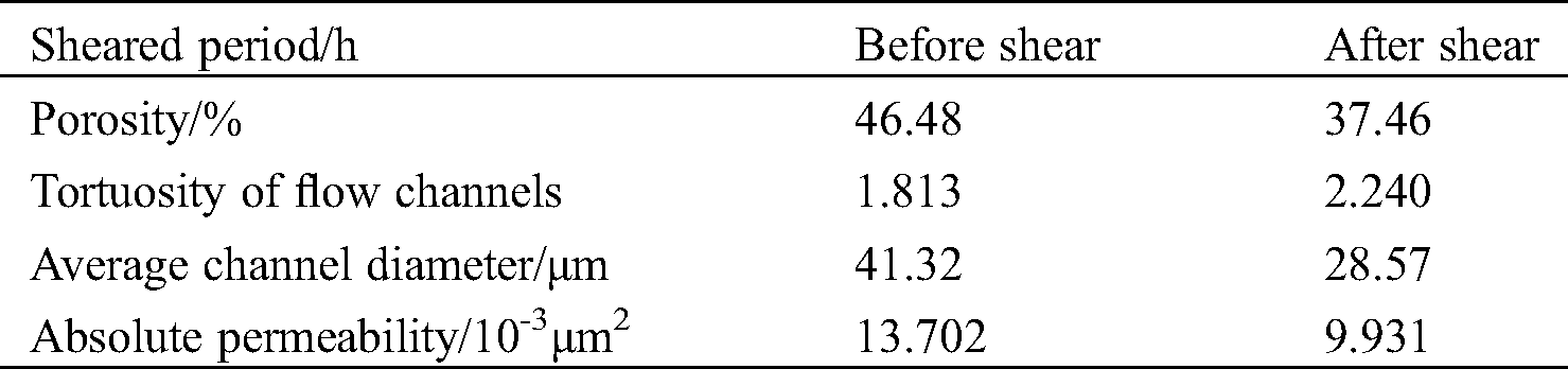
The porosity is the ratio of pore voxel value to total value in the 3D reconstructed model [37,38]. The tailings thickening results showed that the underflow concentrations before and after shearing were 69.6 wt% and 61.4 wt%, at bed height 30 cm, residence time 34 minutes, respectively. The rake shearing reduced the porosity of tailings bed from 46.48% to 37.46%, decreased by 19.41%. The distribution of pore structure in the bed was become looser and more isolated after shearing, as shown in Fig. 5.
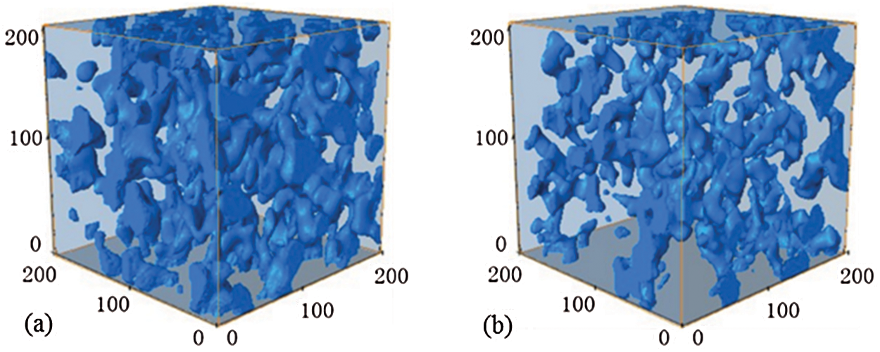
Figure 5: Pore structure visualization (a) before shear (b) after shear
The shearing can make tailings bed compacting, which is beneficial for reducing the porosity of underflow. Parameters CV, RN and AR can characterize the morphological of the single pore, as shown in Figs. 6 and 7.
The bed porosity of before and after shearing is higher in the range of 0.45–0.5 and 0.95–1, the content is 32.09% and 37.51% of total pores, respectively. After shearing, the porosity reached 14.45% in the range of 0.45–0.5 and 0.95–1.0. The CV distribution indicates the pores are mainly shape of round and elliptical, the shape is sensitive to the rake shear.
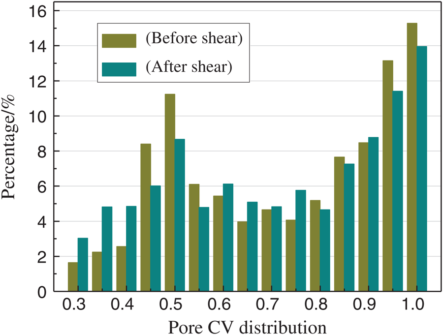
Figure 6: Distribution of CV
The RN before and after shearing are mostly in range of 0.8–1, accounting for 45.28% and 35.85%, respectively. Shearing reduces 0.8–1 RN pores quantity by 20.82%, but the 0–0.8 RN pores shape is not sensitive to shear. The RN distribution indicates pores have acceptable roundness, approximately half circular shape. The data show that shear reduces the content of circular pores.
The AR reflects the ductility of pore geometry. The peak values of pore AR before and after shearing are 2.0 and 3.0, respectively. After reaching the peak value, the number of pores decreases rapidly with the increase of AR. When AR greater than 3.5, pores quantity under before/after shearing reaches 19.57% and 27.21%, respectively. As a result, shearing makes the pores more slender.
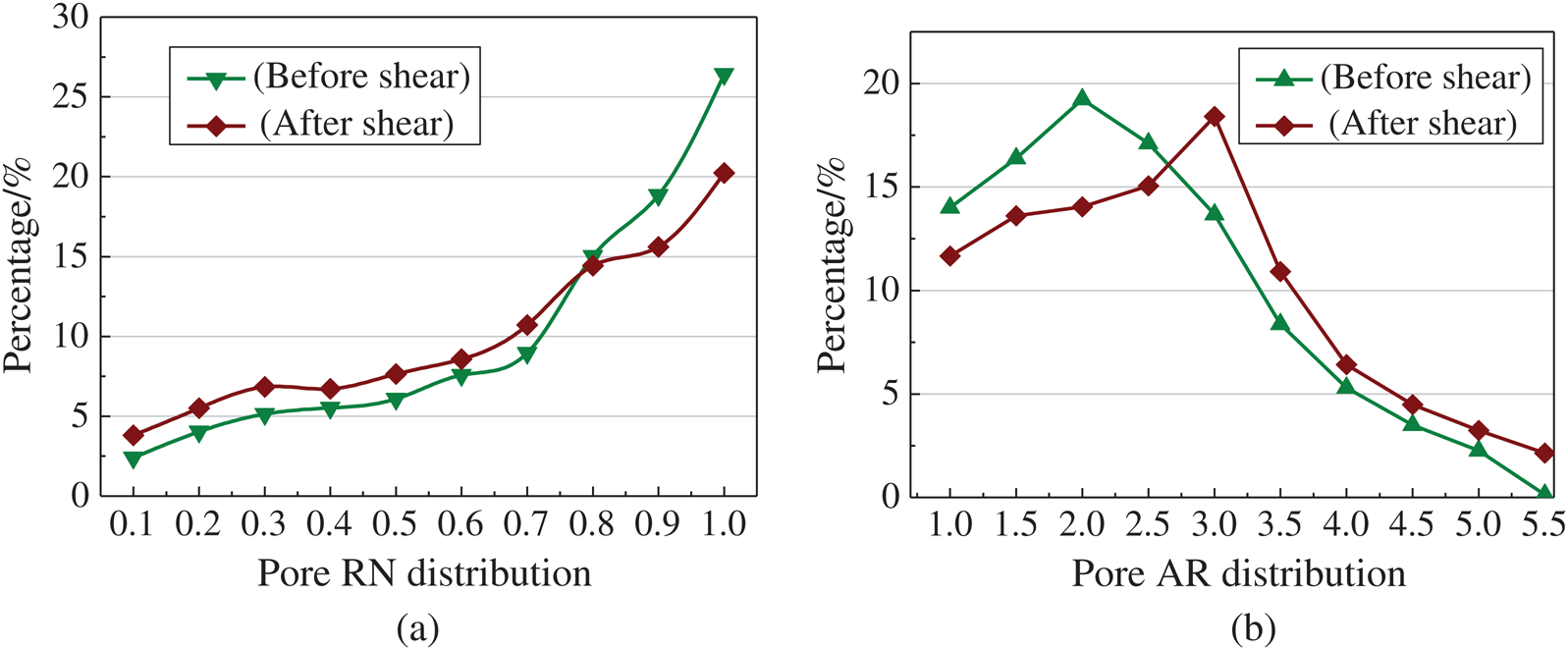
Figure 7: Distribution of Pore RN and AR before and after shearing (a) Roundness (b) Aspect Ratio
The PNM represents the topological structure between pores in bed, as shown in Fig. 8, which also known as the sphere-stick model. The sphere represents the large pore space. The stick body represents thin throat connecting pores. The topological parameters discussion is beneficial for the micro-scale dewatering mechanism explanation.
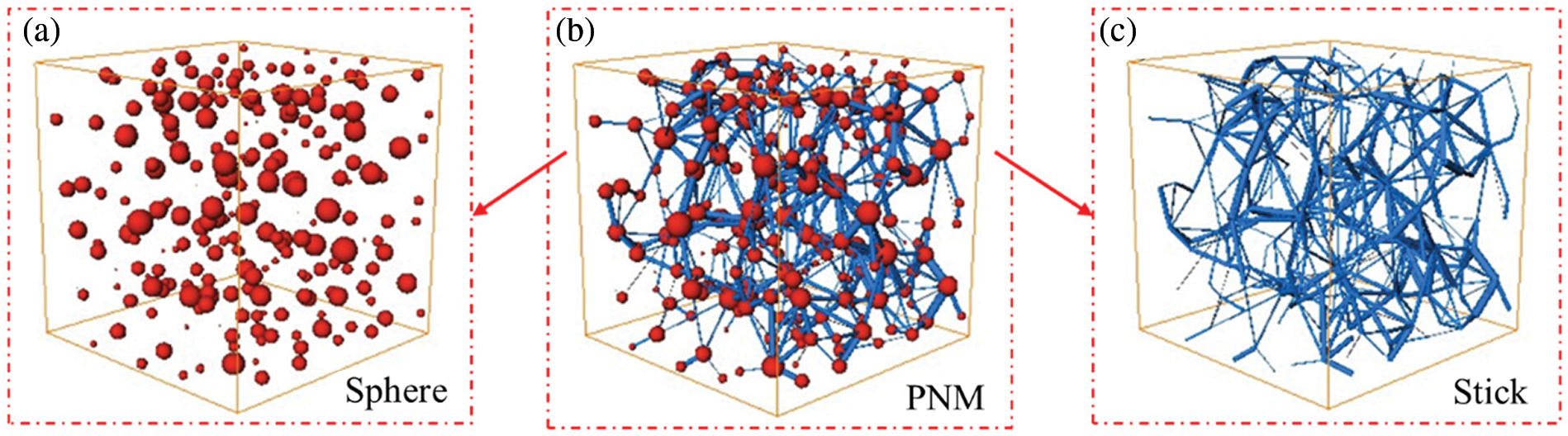
Figure 8: Pore network model (a) Distribution of Spheres in PNM (b) The equivalent PNM (c) Distribution of stick in PNM
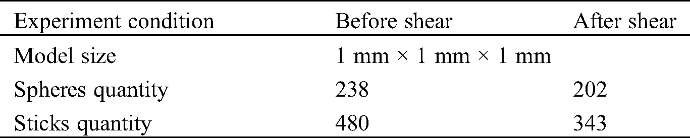
As shown in Tab. 2, the pores quantity before and after shear were 238 and 202, respectively, reduced 15.13% by shearing. The shear has a significant impact on stick quantity, decreased from 480 to 343, reduced by 28.54%. Obviously, the rake shear has more influence on the stick structure rather than sphere.
Table 2: Sphere /stick quantity comparison
The position and geometrical parameters of spheres or sticks are keys to the quantitative description of pores microstructure. The results of sphere radius, stick radius and length, and coordination number is shown in Figs. 9−12.
(1) The radius of spheres after and before shearing is the majority in the range of 20–30 μm, 28.16% and 32.15% respectively. The average radius is 27.80 μm and 32.52 μm with/without shearing, respectively, which is reduced 14.51% by shearing.
(2) The coordination number (CN) represents the connectivity of pore spaces, which is positively correlated with the connectivity. The average CN of the spheres with/without shearing is 9.38 and 10.15, respectively, reduced 7.6% by shearing.
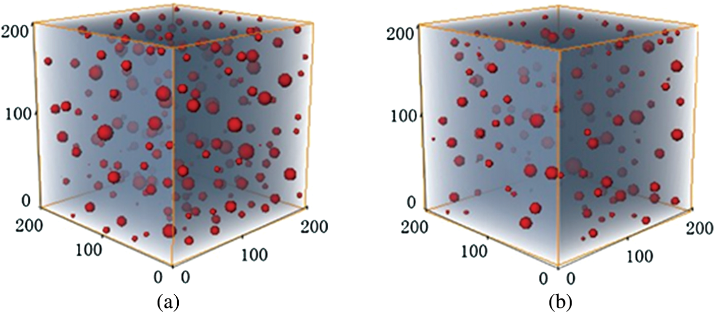
Figure 9: Distribution of spheres in PNM (a) before shear (b) after shear
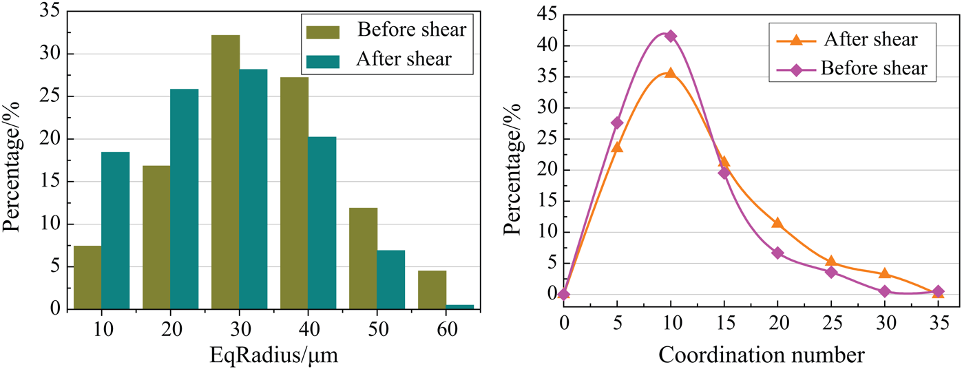
Figure 10: Sphere radius and coordination numbers before and after shearing
(3) The radius of the larger-scale stick body can be reduced by shearing, resulting in a significant decrease in stick radius. The average stick radius was 18.63 μm and 15.07 μm, before and after shearing, respectively, which was reduced 19.11% by shearing. The stick radius distribution is concentrated in the range of 5–10 μm and 0–5 μm, 19.87%, 25.90% of the total, respectively.
(4) Shearing increases the length of stick space, as shown in Fig. 11. In the un-sheared tailings bed, the stick length is majority 40–60 μm, 26.03% of the total; there are about 3.85% stick length longer than 160 μm. On the other hand, the length of the stick body is increased to 60–80 μm by shearing, accounting for 25.33%; about 5.77% of throat length is longer than 160 μm.
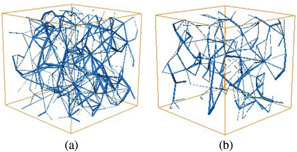
Figure 11: Distribution of stick in PNM (a) before shear (b) after shear
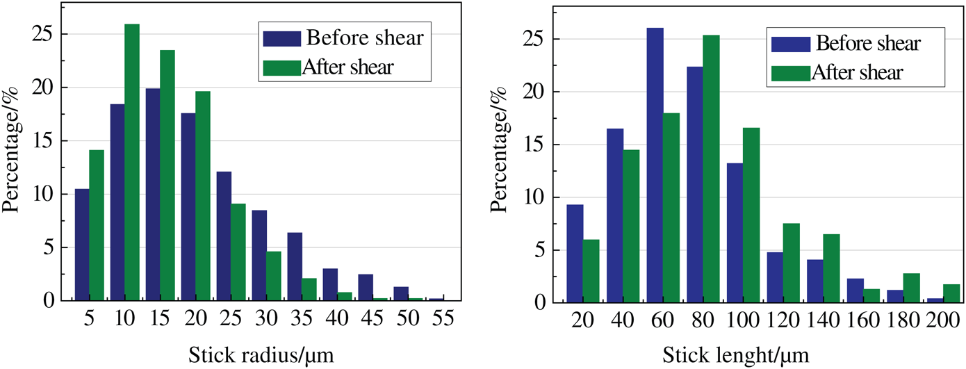
Figure 12: Comparison of stick radius and length by shearing
The shear conducts significant influence on the stick structure rather than the sphere space. The spheres and sticks quantity were decreased by 15.13% and 28.54% by shearing, the average radius was reduced by 14.51% and 19.11%, respectively. The results of morphology and topology indicated that the rake shear made the pores loose, the connectivity deteriorated, and the porosity decreased. The shearing force changes the floc network structure, a large-size pores evolve into several small pores by an external force. The porosity of tailings bed decreases and the underflow concentration increases, indicating that the water entrapped in pores is discharged upward, the source of drainage is mainly from throat (stick) spaces.
The pore network in tailing thickening bed is the storage space and flow channel of moisture. The seepage can be assigned to the PNM to predict the reverse direction seepage in the tailings bed porous media [39].
It is crucial to select the optimal pores sample connectivity to ensure the smooth flow simulation results. Assuming that the seepage flowing in PNM is an incompressible fluid, the inflow and outflow of the connecting pore throat should follow the law of conservation of mass, that is:

The flow formula between any of the two adjacent pores i and j can be derived based on the Hagen-Poiseuille law, as follows:
From Hagen-Poiseuille’s law, the flow formula between two adjacent pores i and j can be derived as follows:

Where, G is the seepage fluid flow rate, μm/s, L is the length of flow channel, μm, P is the seepage pressure, Pa. The pore connectivity of the full flow region is obtained by calculating the average connectivity of the whole spaces between the two pores i and j.
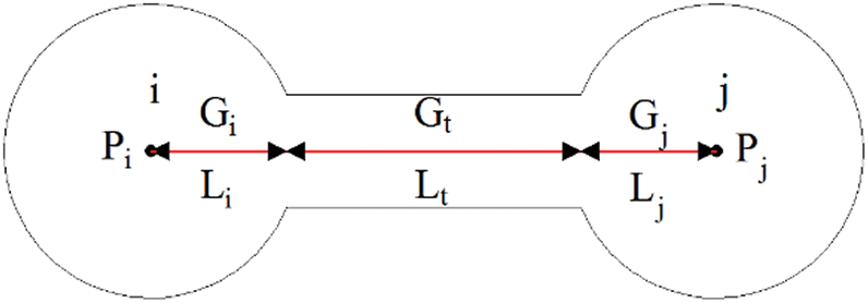
Figure 13: The conductivity definition schematic in a spheres/stick pore unit
Based on Eqs. (4) and (5), all pore spaces in PNM unit can be formed into a system of linear equations, and then the flow between pores can be obtained. The sum of the flow in all the pores on the outlet surface is the total flow in the whole PNM unit.
The pure water was setting as the flow medium, density ρ = 1000 kg/cm3, viscosity μ = 0.001 Pa∙s. The inlet pressure was 1.3 × 10⁵ Pa; outlet pressure was 1.0 × 10⁵ Pa. The bottom boundaries is setting as the velocity inlet, the top is the pressure outlet boundary. The side boundary and wall are regarded as the non-slip wall surface. The simulation, controlled by the combination of Darcy’s law, was conducted to obtain the absolute seepage velocity and flow channels in bed.
The water seepage flow channel was identified and found that the pores and water seepage flow channel have significant relevance. The tailings bed before shear contained a large amount of liquid (blue color in Fig. 14(c), the pores quantity is enough to form the seepage flow channels, as shown in Fig. 14(a). The large diameter flow channel caused lower viscous resistance. The average flow velocity in pores was 1.283 μm/s; the average channel diameter was 41.32 μm, and the absolute permeability was 13.702 × 10⁻³ μm2.
In sheared tailings bed, the entrapped water volume is reduced obviously in Fig. 14(c). The Fig. 14(b) indicates the internal pores and its connection decreased by shearing. The entrapped water was seeping upward through flow channel; tailings particles occupy the original position of water. After the dewatering process, the channels become narrower, which means increased viscous resistance. The average flow velocity in pores is only 1.040 μm/s, which is 18.96% lower than that in the non-shear bed; the average channel diameter is 28.57 μm. The absolute permeability was 9.931 × 10⁻³ μm2, reduced by 27.52%.
The rake shear directly affects the distribution and connectivity of the flow channel, the internal pores of tailings are zigzag, and the liquid seepage flow channels are less, the water has been effectively discharged, the pressure drop mainly occurs at both ends of the test piece; the streamline distribution is sparse, arranged intermittently, the dominant channel disappears, and the permeability is poor. This is due to the evolution of pore structure and the uniform filling of pore space by tailings particles, resulting in the compression of an effective channel. At this time, the channel’s water conductivity is weak, indicating that a large amount of pore water is discharged during the shearing disturbance.
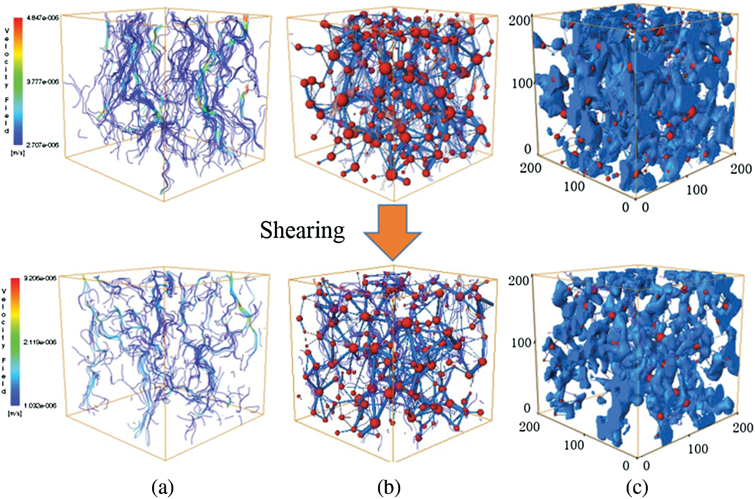
Figure 14: Permeability, pore structure and seepage flow channel with shearing time (a) Seepage flow (b) Topology of the flow channel (c) Pore structure
The tailings thickening bed is a porous medium [40,41], when water flows through the pore structure, the actual flow path is longer than the geometry of the medium. Tortuosity is a degree of flow path twist and tear, which is defined as the ratio of the actual length of the seepage channel to the apparent length (macroscopic distance) through the porous medium, as in Eq. (4).

where: Lt is the length of the curved line, μm; L0 is the length of the straight line of the medium, μm.
From the Tab. 3, comparing the bed state between before and after shearing, the porosity decreased from 46.48% to 37.47%, the tortuosity of flow channels decreased from 1.813 to 2.240, indicating the increased average channel length. The absolute permeability decreased by 27.52%, the average channel diameter increased by 30.86%. The flow rate has increased by 25%. Consequently, it can be concluded that the small tortuosity and the short seepage channel are beneficial for the pores connectivity and permeability, which is helpful for the tailings bed thickening.
Table 3: Permeability parameters in the thickening bed
The flow channel evolution process is containing four stages in the shearing condition. Firstly, the formation stage of the flow channel, the flocs and pores structure were changed by the rake and pickets, the isolated pores connected with surrounding flocs to form branch channel, several branch channels connected to form a major seepage channel. Secondly, the reverse direction seepage stage, at the moment of channel connection, the entrapped water flow upward along the open channel by hydrostatic pressure. Thirdly, the pore network re-organization stage, after the water discharged, the tailings particles occupied the original water spaces, which caused the re-organization of flocs network, the throat of channel tend to be narrow, the major channel evaluated back to the branch channels. At last, the channel disappears stage, the rake shear impacts the flocs structure denser, the pores and channels would be blocked by tailings, the flow channel annihilated. As a result, the tailings bed concentration is increasing, the thickening process arrived a new stage.
(1) The gravity shearing dewatering process can be explained as the flocs and pores structure changed by the rake and pickets, the isolated pores connecting to form seepage channel. The entrapped water flow upward along the open channel by hydrostatic pressure.
(2) Adding 2 rpm rake shear can increases the underflow concentration from 61.4 %wt to 69.6 %wt, decreases the porosity from 46.48% to 37.46%. In the morphological analysis, the pores are mainly shape of round and elliptical, the shape is sensitive to the shear. The microstructure of pore was identified into sphere space and stick space by PNM. The rake shear reduced the quantity of spheres and sticks by 15.13% and 28.54%, respectively, the water released from the pores of the bed is more from the stick space rather than sphere.
(3) The shearing evolution of the seepage flow channel can be divided into four stages, the formation stage of the flow channel, the reverse direction seepage stage, pore network re-organization stage, and the channel disappear stage. After that, the tailings bed is increasing to higher concentration to fulfill the Paste and Thickened Tailings requirement.
Funding Statement: This work was supported by funding from the National Natural Science Foundation of China Projects (51834001, 51704094, U170420041), the China Postdoctoral Science Foundation (2020M672226), Program for Science & Technology Innovation Talents in Universities of Henan Province (19HASTIT047), Key Science Research Project in Universities of Henan Province (19B620001, 20A620004), Henan Polytechnic University Science Fund for Distinguished Young Scholars (J2020-3).
Conflicts of Interest: We declare that we do not have any commercial or associative interest that represents a conflict of interest in connection with the work submitted.
1. Boger, D. V. (2013). Rheology of slurries and environmental impacts in the mining industry. Annual Review of Chemical and Biomolecular Engineering, 4(1), 239–257. DOI 10.1146/annurev-chembioeng-061312-103347. [Google Scholar] [CrossRef]
2. Wu, A. X., Ruan, Z. E., Bürger, R., Yin, S. H., Wang, J. D. et al. (2020). Optimization of flocculation and settling parameters of tailings slurry by response surface methodology. Minerals Engineering, 156, 106488. DOI 10.1016/j.mineng.2020.106488. [Google Scholar] [CrossRef]
3. Yang, Y. X., Zhao, T. Q., Jiao, H. Z., Wang, Y. F., Li, H. Y. (2020). Potential effect of porosity evolution of cemented paste backfill on selective solidification of heavy metal ions. International Journal of Environmental Research and Public Health, 17(3), 814. DOI 10.3390/ijerph17030814. [Google Scholar] [CrossRef]
4. Qi, C. C., Andy, F., Chen, Q. S., Liu, P. F. (2019). Application of first-principles theory in ferrite phases of cemented paste backfill. Minerals Engineering, 133, 47–51. DOI 10.1016/j.mineng.2019.01.011. [Google Scholar] [CrossRef]
5. Jiao, H. Z., Wang, S. F., Wu, A. X., Shen, H. M., Wang, J. D. (2019). Cementitious property of NaAlO2-activated Ge slag as cement supplement. International Journal of Minerals Metallurgy and Materials, 26(12), 1594–1603. DOI 10.1007/s12613-019-1901-y. [Google Scholar] [CrossRef]
6. Xue, Z. L., Gan, D. Q., Zhang, Y. Z., Liu, Z. Y. (2020). Rheological behavior of ultrafine-tailings cemented paste backfill in high-temperature mining conditions. Construction and Building Materials, 253, 119212. DOI 10.1016/j.conbuildmat.2020.119212. [Google Scholar] [CrossRef]
7. Lu, H. J., Qi, C. C., Chen, Q. S., Gan, D. Q., Xue, Z. L. et al. (2018). A new procedure for recycling waste tailings as cemented paste backfill to underground stopes and open pits. Journal of Cleaner Production, 188, 601–612. DOI 10.1016/j.jclepro.2018.04.041. [Google Scholar] [CrossRef]
8. Jiang, L., Yang, C., Jiao, H. (2020). Ultimately exposed roof area prediction of bauxite deposit goaf based on macro joint damage. International Journal of Mining Science and Technology, 30(5), 699–704. DOI 10.1016/j.ijmst.2020.06.005. [Google Scholar] [CrossRef]
9. Sun, Q., Tian, S., Sun, Q. W., Li, B., Cai, C. G. et al. (2019). Preparation and microstructure of fly ash geopolymer paste backfill material. Journal of Cleaner Production, 225, 376–390. DOI 10.1016/j.jclepro.2019.03.310. [Google Scholar] [CrossRef]
10. Cao, S., Song, W. D., Yilmaz, E. (2018). Influence of structural factors on uniaxial compressive strength of cemented tailings backfill. Construction and Building Materials, 174, 190–201. DOI 10.1016/j.conbuildmat.2018.04.126. [Google Scholar] [CrossRef]
11. Zhao, H. B., Zhang, Y. S., Zhang, X., Qian, L., Sun, M. L. et al. (2019). The dissolution and passivation mechanism of chalcopyrite in bioleaching: An overview. Minerals Engineering, 136, 140–154. DOI 10.1016/j.mineng.2019.03.014. [Google Scholar] [CrossRef]
12. Sakuhuni, G., Klein, B., Altun, N. E. (2015). A hybrid evolutionary performance improvement procedure for optimisation of continuous variable discharge concentrators. Separation and Purification Technology, 145, 130–138. DOI 10.1016/j.seppur.2015.02.030. [Google Scholar] [CrossRef]
13. Jeldres, M., Piceros, E. C., Toro, N., Robles, P., Nieto, S. et al. (2020). Enhancing the sedimentation of clay−based tailings in seawater by magnesium removal treatment. Separation and Purification Technology, 242, 116762. DOI 10.1016/j.seppur.2020.116762. [Google Scholar] [CrossRef]
14. Reis, L. G., Oliveira, R. S., Palhares, T. N., Spinelli, L. S., Lucas, E. F. et al. (2016). Using acrylamide/propylene oxide copolymers to dewater and densify mature fine tailings. Minerals Engineering, 95, 29–39. DOI 10.1016/j.mineng.2016.06.005. [Google Scholar] [CrossRef]
15. Motta, F. L., Gaikwad, R., Botha, L., Soares, J. B. (2018). Quantifying the effect of polyacrylamide dosage, Na+ and Ca2+ concentrations, and clay particle size on the flocculation of mature fine tailings with robust statistical methods. Chemosphere, 20(8), 263–272. DOI 10.1016/j.chemosphere.2018.05.171. [Google Scholar] [CrossRef]
16. Sharma, S., Lin, C. L., Miller, J. D. (2017). Multi-scale features including water content of polymer induced kaolinite floc structures. Minerals Engineering, 101, 20–29. DOI 10.1016/j.mineng.2016.11.003. [Google Scholar] [CrossRef]
17. Di, L., Mansour, E., Luke, B. (2018). Investigating the settling behaviour of saline tailing suspensions using kaolinite, bentonite, and illite clay minerals. Powder Technology, 326, 228–236. DOI 10.1016/j.powtec.2017.11.070. [Google Scholar] [CrossRef]
18. Mpofu, P., Addai-mensah, J., Ralston, J. (2004). Flocculation and dewatering behaviour of smectite dispersions: Effect of polymer structure type. Minerals Engineering, 17(3), 411–423. DOI 10.1016/j.mineng.2003.11.010. [Google Scholar] [CrossRef]
19. Mpofu, P., Addai-mensah, J., Ralston, J. (2003). Influence of hydrolyzable metal ions on the interfacial chemistry, particle interactions, and dewatering behavior of kaolinite dispersions. Journal of Colloid and Interface Science, 261(2), 349–359. DOI 10.1016/S0021-9797(03)00113-9. [Google Scholar] [CrossRef]
20. Vaezi, F. (2013). Effect of Laminar Shear on the Aggregate Structure of Flocculant-dosed Kaolinite Slurries, Doctor Thesis, University of Alberta. [Google Scholar]
21. Li, S., Wang, X. M., Zhang, Q. L. (2016). Dynamic experiments on flocculation and sedimentation of argillized ultrafine tailings using fly-ash-based magnetic coagulant. Transactions of Nonferrous Metals Society of China, 26(7), 1975–1984. DOI 10.1016/S1003-6326(16)64308-X. [Google Scholar] [CrossRef]
22. Neelakantan, R., Vaezi, F., Sanders, R. S. (2018). Effect of shear on the yield stress and aggregate structure of flocculant−dosed, concentrated kaolinite suspensions. Minerals Engineering, 123, 95–103. DOI 10.1016/j.mineng.2018.03.016. [Google Scholar] [CrossRef]
23. Spehar, R., Kiviti-manor, A., Fawell, P., Usher, S. P. Rudman, M. et al. (2015). Aggregate densification in the thickening of flocculated suspensions in an un−networked bed. Chemical Engineering Science, 122, 585–595. DOI 10.1016/j.ces.2014.10.018. [Google Scholar] [CrossRef]
24. Gladman, B. R., Rudman, M., Scales, P. J. (2010). The effect of shear on gravity thickening: Pilot scale modelling. Chemical Engineering Science, 65(14), 4293–4301. DOI 10.1016/j.ces.2010.04.010. [Google Scholar] [CrossRef]
25. Tian, J. Y., Ni, L., Song, T., Olson, J., Zhao, J. N. (2018). An overview of operating parameters and conditions in hydrocyclones for enhanced separations. Separation and Purification Technology, 206, 268–285. DOI 10.1016/j.seppur.2018.06.015. [Google Scholar] [CrossRef]
26. Zhai, D., Feng, B., Guo, Y. T., Zhou, X. T., Wang, T. et al. (2019). Settling behavior of tungsten tailings using serpentine as flocculant. Separation and Purification Technology, 224, 304–307. DOI 10.1016/j.seppur.2019.05.029. [Google Scholar] [CrossRef]
27. Ruan, Z., Wang, Y., Wu, A. X., Yin, S. H., Jin, F. et al. (2019). A theoretical model for the rake blockage mitigation in deep cone thickener: A case study of Lead-Zinc mine in China. Mathematical Problems in Engineering, 1, 1–7. [Google Scholar]
28. Sun, W., Wu, A. X., Hou, K. P., Yang, Y., Liu, L. et al. (2016). Real−time observation of meso−fracture process in backfill body during mine subsidence using X-ray CT under uniaxial compressive conditions. Construction and Building Materials, 113, 153–162. DOI 10.1016/j.conbuildmat.2016.03.050. [Google Scholar] [CrossRef]
29. Zhou, T., Li, M., Li, Q. L., Lei, B. Zhou, Q. et al. (2014). Numerical simulation of flow regions in red mud separation thickener’s feedwell by analysis of residence-time distribution. Transactions of Nonferrous Metals Society of China, 24(4), 1117–1124. DOI 10.1016/S1003-6326(14)63170-8. [Google Scholar] [CrossRef]
30. Chen, Q., Zhang, Q., Qi, C. (2018). Recycling phosphogypsum and construction demolition waste for cemented paste backfill and its environmental impact. Journal of Cleaner Production, 186, 418–429. DOI 10.1016/j.jclepro.2018.03.131. [Google Scholar] [CrossRef]
31. Yin, S. H., Wang, L. M., Wu, A. X., Kabwe, E., Chen, X. et al. (2018). Copper recycle from sulfide tailings using combined leaching of ammonia solution and alkaline bacteria. Journal of Cleaner Production, 189, 746–753. DOI 10.1016/j.jclepro.2018.04.116. [Google Scholar] [CrossRef]
32. Jiao, H. Z., Wang, S. f, Yang, Y. X., Chen, X. M. (2020). Water recovery improvement by shearing of gravity-thickened tailings for cemented paste backfill. Journal of Cleaner Production, 245, 118882. DOI 10.1016/j.jclepro.2019.118882. [Google Scholar] [CrossRef]
33. Westcott, R. (2014). Three−dimensional geomodeling to identify spatial relations between lithostratigraphy and porosity in the karst carbonate Biscayne aquifer, southeastern Florida. Florida Atlantic University. [Google Scholar]
34. Yuan, Q., Xu, J. Z., Wang, Y. Y., Zhang, X. H., Pang, Y. E. et al. (2019). Mixing state and fractal dimension of soot particles at a remote site in the southeastern Tibetan plateau. Environmental Science & Technology, 53(14), 8227–8234. DOI 10.1021/acs.est.9b01917. [Google Scholar] [CrossRef]
35. Zheng, W. B., Hu, X. L., Dwayne, D. (2020). Tannant. Shape characterization of fragmented sand grains via X-ray computed tomography imaging. International Journal of Geomechanics, 20(3), 04020003. [Google Scholar]
36. Zhang, Y. Q., Gao, W. J., Pedram, F. (2019). Structure and settling performance of aluminum oxide and poly (acrylic acid) flocs in suspension systems. Separation and Purification Technology, 215, 115–124. [Google Scholar]
37. Chen, X. M., Jin, X. F., Jiao, H. Z., Yang, Y. X., Liu, J. H. (2020). Pore connectivity and dewatering mechanism of tailings bed in raking deep−cone thickener process. Minerals, 10(4), 375. [Google Scholar]
38. Jiao, H. Z., Wang, S. F., Wu, A. X., Shen, H. M., Yang, Y. X. et al. (2019). Pore network model of tailings thickener bed and water drainage channel evolution under the shearing effect. Chinese Journal of Engineering, 41(8), 987–996. DOI 10.13374/j.issn2095-9389.2019.08.004. [Google Scholar] [CrossRef]
39. Wang, G., Shen, J. N., Liu, S. M., Jiang, C. H., Qin, X. J. (2019). Three-dimensional modeling and analysis of macro-pore structure of coal using combined X-ray CT imaging and fractal theory. International Journal of Rock Mechanics and Mining Sciences, 123, 104082. [Google Scholar]
40. Hu, J. H., Ren, Q. F., Ma, S. W., Jiang, Q., Jiang, Y. J. et al. (2019). Macroscopic and microscopic trans-scale characteristics of pore structure of mine grouting materials. Transactions of Nonferrous Metals Society of China, 29(5), 1067–1081. [Google Scholar]
41. Mountrakis, L., Lorenz, E., Hoekstra, A. G. (2017). Revisiting the use of the immersed-boundary lattice-Boltzmann method for simulations of suspended particles. Physical Review E, 96(1), 013302. [Google Scholar]
 | This work is licensed under a Creative Commons Attribution 4.0 International License, which permits unrestricted use, distribution, and reproduction in any medium, provided the original work is properly cited. |