Materials
| Journal of Renewable Materials |
DOI: 10.32604/jrm.2021.015452
ARTICLE
The Measurement of the Local Slip in Bamboo-Reinforced Concrete Beams Using Moment-Curvature and Bond-Stress
Faculty of Engineering, University of Muhammadiyah Jember, Jember, 68121, Indonesia
*Corresponding Author: Muhtar. Email: muhtar@unmuhjember.ac.id
Received: 19 December 2020; Accepted: 07 February 2021
Abstract: This paper presents a method of measuring local slip in bamboo-reinforced concrete beams. Local slips (so) are calculated by reducing the elongation of the bamboo reinforcement (ebo) with the elongation of the concrete (eco). The elongation of bamboo reinforcement (ebo) is determined in two ways, namely, read directly through a strain-gauge mounted on the bamboo reinforcement and calculated based on the force analysis or curvature moment as a control. The elongation of the concrete (eco) is calculated using force analysis or curvature moment. The process of calculating curvature moments and bond stress employs the Excel program. The steps in calculating the elongation of concrete (eco) consist of calculating the curvature moment, calculating the bond-stress at the initial crack, and calculating the bond-stress at the second crack until the beam collapses. Further, the results of the calculation of the elongation of the concrete (eco) and the elongation of the bamboo reinforcement (ebo) resulting from the reading of the strain-gauge are substituted in the local slip calculation equation. The results of the calculation analysis show that the local slip is approaching the local slip resulting from the experiment. The relationship behavior of bond-stress vs. slip indicates conformity with the experimental results. The local slip calculation based on the moment-curvature can be considered as control of the experiment result.
Keywords: Local slip; bamboo-reinforced concrete (BRC); moment-curvature; bond-stress
List of symbols
| u: | Bond-stress (MPa) |
| ubo: | The peak of bond-stress (MPa) |
| ub: | Local bond-stress (MPa) |
| Ubx: | Total bond-force (N) |
| ubx: | Bond stress at a distance x away from the zero-slip section (MPa) |
| V: | Shearing force of the beam (N) |
| ∑o: | Circumference of the cross-section of bamboo reinforcement |
| d: | Distance from the maximum press fiber to the center of the bamboo tensile reinforcement area (mm) |
| a: | Height of concrete stress block equivalent (mm) |
| jd: | The internal lever arm = d–½ a |
| εbo: | A strain of bamboo reinforcement |
| εbc: | Bamboo strain in cross-section Z |
| εbx: | Bamboo strain function |
| ebo: | Elongation of bamboo reinforcement (mm) |
| eco: | Elongation of concrete (mm) |
| ec,co: | Elongation of concrete due to the compressive force (mm) |
| ec,bo: | Elongation of concrete due to bond force (mm) |
| L: | Span length (at Fig. 3) (mm) |
| Lo: | ½ crack distance the side left plus ½ crack distance the side right of the observation point as shown in Fig. 5 and Eq. (3) for the local-slip (mm) |
| ϕ: | Bamboo reinforcement diameter (mm) |
| fb1: | Bamboo stress at an uncracked section, bamboo stress at zero-slip point (N/mm2) |
| fb2: | Bamboo stresses at cracked sections (N/mm2) |
| fbt1: | The stress of bamboo reinforcement at slip length (at the zero-slip point as shown in Fig. 5) (N/mm2) |
| fbt2: | The stress of bamboo reinforcement at slip length (at the crack point as shown in Fig. 5) (N/mm2) |
| BRC: | Bamboo Reinforced Concrete |
| SRC: | Steel Reinforced Concrete |
| S: | Crack spacing (mm) |
| Sx: | Distances from the cracked sections to zero slip point (mm) |
| So: | Slip length or 1/2 the distance between two adjacent cracks (mm) |
| so: | Local slips at the points where the peak bond stresses occur (mm) |
| s: | Slip (mm) |
| fc’: | Characteristic strength of concrete (MPa) |
| fbx: | Bamboo stress at a distance x from zero-slip section (MPa) |
| fbtx: | Bamboo stress function at slip length (MPa) |
| fbt1: | Bamboo stress at zero-slip point (MPa) |
| fbt2: | Bamboo stress at a crack point (MPa) |
| Φ′(So): | Constitutive relationship |
| Eb: | Modulus of elasticity of bamboo (N/mm2) |
| M1: | Bending moment at the supports in a continuous beam (N-mm) |
| M2: | Bending moment at mid-span in a continuous beam (N-mm) |
| ρ: | Tension reinforcement ratio |
| Abt: | Area of tensile reinforcement (mm2) |
| b: | Beamwidth (mm) |
Research on bamboo as reinforcing concrete has been done a lot and the majority of failures are the failure of adhesion between bamboo and concrete. The main factors causing adhesive failure are the lower elastic modulus of bamboo than concrete, hygroscopic properties, and the hydrolysis process. The difference in the modulus of elasticity of bamboo which is lower than concrete causes the concrete not to grip the bamboo reinforcement after the cement hydration process, which eventually occurs swelling [1]. This shows that bamboo reinforcement cannot bond with the concrete (no direct contact) post hardened concrete. To overcome the weaknesses of bamboo requires treatment such as soaking, drying [2] adding waterproof coatings such as Sikadur®-752 [3,4], and strengthening bond-stress. Therefore, bamboo as concrete reinforcement does not have a significant effect without treatment and waterproof layer adhesive. Treatment and application of waterproof layer adhesive is a must.
There are many ways to prevent the hygroscopic process between bamboo reinforcement and concrete during the hydration process. The use of adhesives and waterproof coatings such as Sikadur 32 Gel [5−7]; Sikadur 32 LP [8]; Sikadur®-752 [9,10]; asphalt and bitumen [11]; Concresive 1315 [12]; paint [13]; Sikadur-31CFN [14]; Araldite Epoxy Resin Coal Tar [15]; synthetic resin and synthetic rubber [16]; lime water treated bamboo mat coated with epoxy and sand [8]; TrueGrip BP with coarse sand, water-based epoxy coating with fine sand, TrueGrip EP with coarse sand, Exaphen with coarse sand, and enamel, water-based epoxy coating with coarse sand, [1]. Meanwhile, to calculate water absorption in bamboo reinforcement can use method A from ASTM 4442-92 [17].
Reinforced concrete bonds are formed by the mechanism of adhesion, friction, and mechanical interlock between reinforcement and concrete. The bond strength is strongly influenced by the fracture energy [18] as well as the complex interactions between local deformation, chemical adhesion, and other factors [19]. As for the interlock mechanism of bamboo reinforced concrete, the transfer of shear forces between bamboo reinforcement and concrete is the dominant factor after adhesive bonding. The application of adhesive, waterproof layer and modification of the surface roughness of bamboo reinforcement are efforts to increase bond-stress and prevent slippage. Several methods to increase adhesion strength and prevent slippage between bamboo reinforcement and concrete include modifying the roughness such as by notching [20,21], coir winding [22], adding hooks [23], or installing hose clamps [3].
Bamboo has high elastic properties due to the high tensile strength of bamboo fibers. Archila et al. [24] in their summary wrote that Bamboo is essentially an elastic brittle material. Bamboo has elastic properties that will be advantageous in the post-cracking behavior of reinforced concrete which requires sufficient bonding between bamboo and concrete. The elastic properties of bamboo is an opportunity to be investigated. Some of the advantages of BRC beams include: (1) BRC beam has high elastic properties which can absorb energy after the ultimate load of 33 kN [3]. After the ultimate load is released, the beam returns to flatness or deflection tends to return to zero as shown in the video on the following link: https://goo.gl/6AVWmP [3,4]; (2) BRC beams are one of the construction elements with low-cost, renewable materials, reduce environmental pollution, easy to get, and bamboo is very abundant in tropical and subtropical areas around the world [5].
The reference for calculating the bond stress and slip of bamboo reinforcement with concrete is based on the reference for calculating the bond stress and slip of steel reinforcement. Several references are used as a basis including Diab et al. [25], Siempu et al. [26], Tang et al. [27], Wang et al. [28], Wang et al. [29], Jacques et al. [30], Lin et al. [31], and Piyasena et al. [32].
Diab et al. [25] conducted a pull-out test of 16 mm diameter steel reinforcement embedded in concrete, and propose a bond-stress vs. slip relationship model with a limit point of “friction bond limit” of 50%, a limit point of “proof bond strength” of 60%, and a limit point of “bond-stress at pre-cracking” of 70%. The embedded length of steel reinforcement in concrete affects increasing the ultimate tensile bond strength and ultimate slip. The crack length affects decreasing the adhesive strength and increasing the slip. Cracked specimens lose about 30% of their bond strength. Cracks can reduce the stiffness of the concrete section, and make the distribution of bond stresses uneven along the length of the reinforcement bar.
Siempu et al. [26] conducted a study on the parameters influencing flexural bond stress in reinforced concrete and concluded that with increasing concrete strength, the bond-stress increases. The flexural bond-stress is lower than the bond-stress from the pull-out test. Tang et al. [27] predicts modeling relationships local bond stress vs. slip of reinforcing bars embedded in concrete with different strengths, and propose an empirical formula for the ultimate local bond stress is a function of the strength of the concrete, the thickness of the concrete cover, and the diameter of the reinforcement, which are following the experimental values. Wang et al. [28] examine the bond-slip performance and constitutive model of the interface between reinforcing steel bars and brick masonry. They concluded that the initial bond stiffness of the micro-slip segment increases with increasing vertical compressive stress, and the ultimate bond stress increases significantly. However, this model cannot be adopted due to different test methods and specimens.
Wang et al. [29] examines the crack propagation process of lightly reinforced concrete beams considering bond-slip behavior. The conclusion shows that the bond-slip behavior has a significant effect on the crack extension properties. Beam failure is usually due to the formation and growth of one central crack. When cracks penetrate through the reinforcing zone, slip between the reinforcement and concrete begins, and then the interface shear stress increases, which causes debonding of the reinforcing-concrete interface. Jacques et al. [30] investigated the effect of high strain rates on reinforcing bonds in concrete. High levels of strain were found to significantly increase the bond end bond strength of the beam, whereas they do not significantly affect the general shape of the curve of bond stress vs. slip. Lin et al. [31] examined the bond-slip behavior of FRP-reinforced concrete beams, and one of his conclusions wrote that bond-slip was proven to have a major effect on the flexural behavior of FRP reinforced concrete beams. BFRP reinforced concrete beams perform much better than other reinforced concrete beam specimens due to the strong bonding of BFRP reinforced concrete beams.
This study discusses the slip calculation method on bamboo reinforced concrete beams (BRC) based on moment-curvature and bond-stress. Some of the difficulties in obtaining slip data between reinforcement and concrete from the experimental results are obtaining concrete elongation (eco) data and reinforcement elongation. The difficulty in finding concrete elongation (eco) is usually due to the installation of the concrete strain-gauge is inaccurate or damage. Meanwhile, difficulties in obtaining reinforcement elongation usually occur after the initial crack due to the yielding and damaged reinforcement. The limitation of measurement and local slip analysis in this study was carried out at predetermined observation points, namely at the time of the initial crack, the second crack, the third crack, and until the crack at the ultimate load. It is suspected that the calculation method in this study can be a solution to get the length of the slip that occurs.
2.1 The Materials and Experiment
The specimens used in the study were eight pieces of bamboo reinforced concrete beam with single reinforcement. The size of the beams is 75 mm × 150 mm × 1100 mm. The geometry and reinforcement details of BRC beams are shown in Fig. 1. Installation of hose-clamp at both ends of the bamboo reinforcement functions as a hook-like such as steel reinforcement. Material properties of bamboo reinforcement and concrete are shown in Tab. 1. Beams are flexural tested using the four-point load method [33] as shown in Fig. 2.
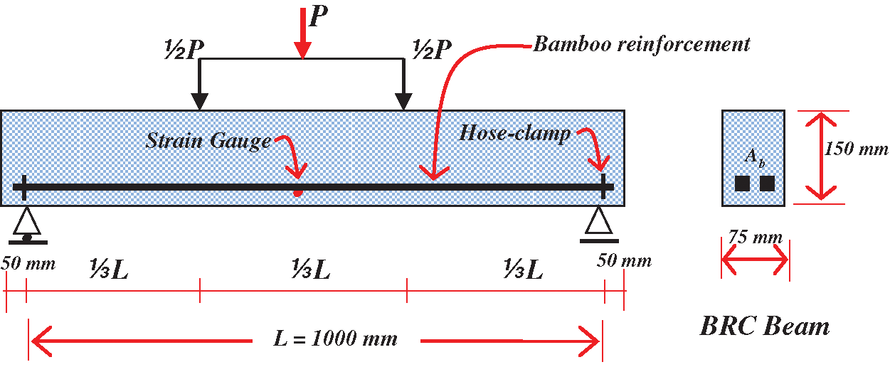
Figure 1: Detail and geometry of the bamboo reinforced concrete beam
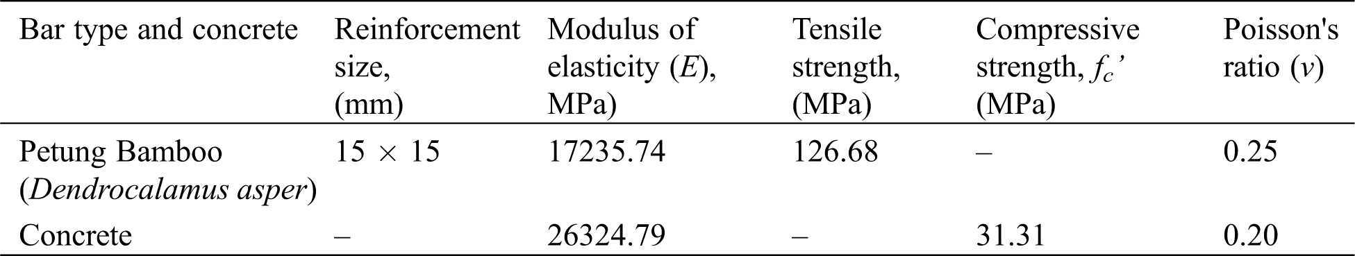
Table 1: Material properties of bamboo reinforcement and concrete
There are 16 specimens of BRC beams, consisting of 4 variations of the area of bamboo reinforcement, namely 100 mm2, 140 mm2, 200 mm2, and 450 mm2. The BRC beam specimen has 2 strain gauges installed on the bamboo reinforcement to detect the elongation of the bamboo reinforcement as shown in Figs. 1 and 2. 2 pieces of strain gauge are installed on the bamboo reinforcement in the middle of the span as shown in Fig. 2. The purpose of the installation of strain gauge is to obtain the elongation of bamboo reinforcement in the calculation of the local slip (slip in the middle of the measured span), and this is also to control the extension of the calculated reinforcement through curvature moment and bond stress. Elongation of bamboo reinforcement is obtained in two ways, namely through the experiment of the BRC beam and through calculation curvature moment and bond-stress based on experimental data such as loading history data and crack patterns. Because the installation of strain-gauge at the observation point is limited, then the lengthening of the bamboo reinforcement from the experiment needs to be controlled by the results of the lengthening of the bamboo reinforcement with the results of moment-curvature analysis and the bond stress.
The elongation of bamboo reinforcement from the experimental results is obtained from the formula ε = ebo/Lo, with Lo is ½ crack distance the side left plus ½ crack distance the side right of the observation point. The strain-gauge is mounted by attaching it to the bamboo reinforcement with sufficiently elastic insulation to prevent damage after the initial crack occurs. But in reality, strain-gauge readings on the BRC beam can continue to be carried out until the ultimate load and even the BRC beam collapse. This proves that the strain-gauge and bamboo reinforcement are not damaged, as shown in the video on the following link: https://goo.gl/6AVWmP [3]. The video shows that the BRC beam has good elastic properties. The maximum deflection that occurs tends to return to zero after the load is released landed, or the BRC beam returns flat [34].
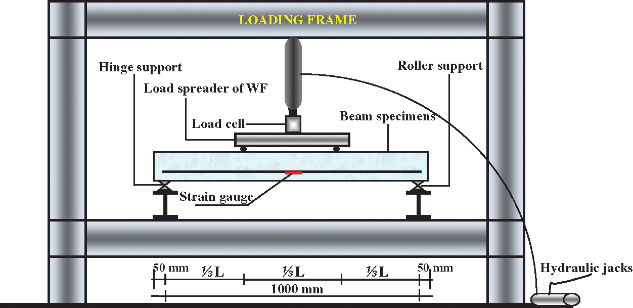
Figure 2: Flexural test settings for the four-point flexural test method [33]
The load is applied at a distance of ⅓L from the beam support, using the WF load spreader. The strain gauge is attached to the bamboo reinforcement with a distance of ½L from the span of the beam. The strain gauge is connected to a digital strain-meter. Hydraulic jacks are used for beam loading with a 200 kN load cell connected to the data logger. Crack patterns and failure patterns were observed and identified from the first crack to the collapse of the beam. Crack pattern data and loading history are used as input data for calculating slip through moment-curvature and bond stress. The test equipment setup and load scheme are shown in Fig. 2.
Crack patterns and flexural behavior in steel-reinforced concrete beams are used as the basis for this method. How crack and bond-slip patterns occur is shown in Figs. 3 and 4 [32]. When there is an initial flexural crack on the BRC beam under load, the stress of the bamboo reinforcement on the cross-section of the crack increases because the tensile stress on the concrete is transferred to the bamboo reinforcement. This increase in bamboo stress is held up by bond-forces that occur along with the reinforcement on both sides of the crack. This bond force is associate with a bond-slip, and the length of the bond-slip is dependent on the increase in the bamboo reinforcement stress as the bond-stress relationship, bond-slip, and reinforcement dimensions.
The basic formula for calculating the bond-stress (u) is based on the formula Park et al. [35] in Chapter 9 sub-chapter 9.1.3 Flexural Bond. The local slip (so) calculation as shown in Eq. (9) is based on the Piyasena formula [32] through the moment-curvature of the beam section, the bond-stress of the first crack, and the bond-stress of the second crack until collapses beam. Piyasena formulas [32] starting from Eqs. (4)–(19) were translated or counted by an excel program. Figs. 3 and 4 shows the beam section after the initial bending crack occurred in cross-section A. Increased bamboo reinforcement stress due to cracking that occurs in the form of a slip So. Distance So is referred to as slip length. The bamboo reinforcement stress fbt at both ends of the bamboo reinforcement and bond force Ubx along So is shown in Fig. 4a. The variation of bond stress ubo and bamboo reinforcement stress fbt on the slip length is shown in Figs. 4b and 4c. While elongation of bamboo reinforcement ebo is shown in Fig. 4d. The elongation of bamboo reinforcement is zero at the x = 0 position due to the bond stress equal to zero, while the tensile stress of bamboo reinforcement at the x = 0 position is not equal to zero as shown in Figs. 3 and 4.
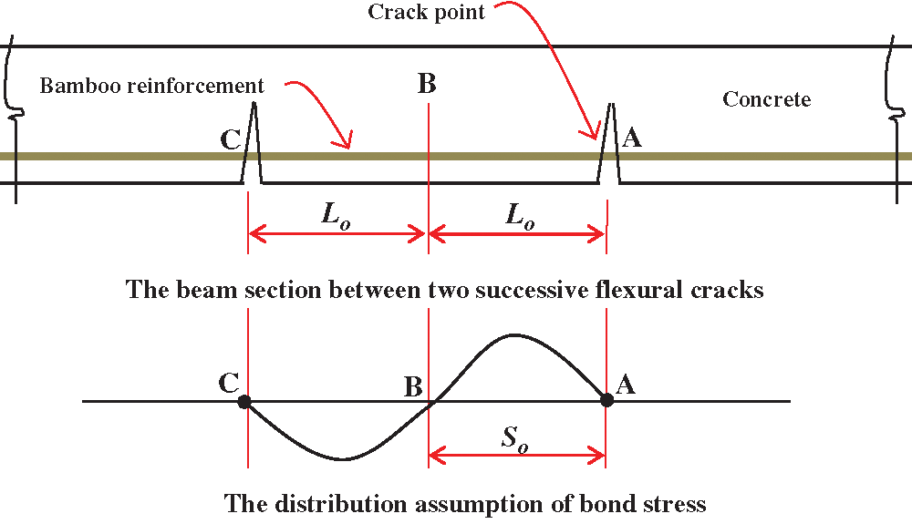
Figure 3: The flexural cracks and the distribution assumption of bond stress on the beam section [32]
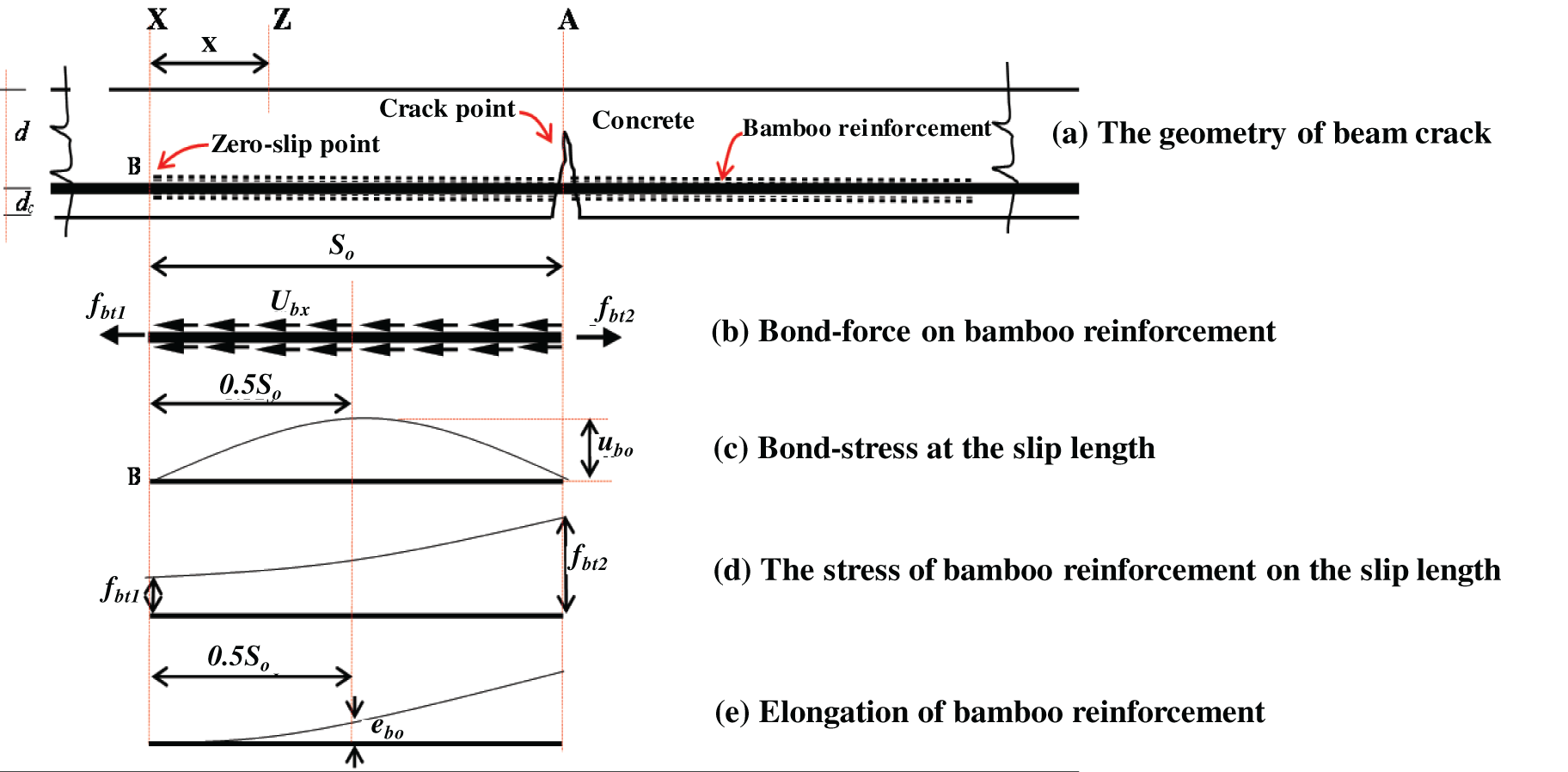
Figure 4: The initial flexural cracks on the BRC beam; (a) the geometry of BRC beam crack; (b) bond-force on bamboo reinforcement; (c) bond-stress at slip length; (d) the stress of bamboo reinforcement at slip length; (e) elongation of bamboo reinforcement [32]
Preparation for the calculation process is to carry out the flexural test to the BRC beam. A strain gauge is attached to the bamboo reinforcement. The data from the strain gauge readings were analyzed according to the loading stage and the cracking process. The calculation of elongation of bamboo reinforcement (ebo) is obtained from the strain formula as shown in Eq. (3). Elongation of concrete (eco) is calculated through the curvature moment by entering material data, geometry data, load data, crack behavior, and other experimental data, and these data are used to calculate curvature-moment, the calculation of bond-stress, and slip when the initial crack, and the calculation of bond-stress and slip when the second crack until the beam collapses. The details of the calculation process are shown in Fig. 5.
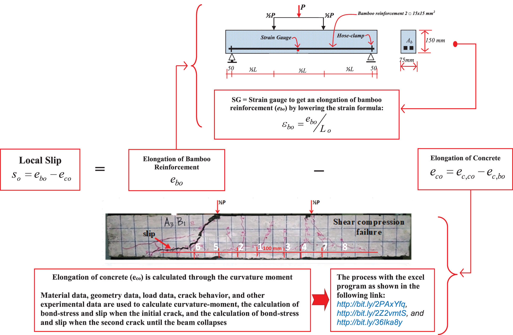
Figure 5: The slip calculation process of the BRC beam
The local slip (so) calculation method is based on experimental results data and analysis of curvature moments in cross-sections of bamboo-reinforced concrete beams. The geometry of the beam test specimen for the experiment is shown in Fig. 1 and the beam specimen test settings are shown in Fig. 2. The calculations of bond-stress are carried out in two ways, namely using the approach formula as shown in Eqs. (1) and (2) and through curvature-moment analysis as control. Local slip (so) calculation is carried out in two ways, namely through the reading of the strain-gauge for elongation of bamboo reinforcement (ebo) using Eq. (3) and through the curvature-moment for elongation of concrete (eco). The elongation of bamboo reinforcement (ebo) from the curvature-moment analysis is used as a control for the elongation of bamboo reinforcement (ebo) from the strain-gauge reading. Bond-stress and local slip calculations through the curvature-moment are performed using an Excel program based on Eqs. (4)−(19). Bond-stress data from the curvature-moment analysis is used as bond-stress control from calculations using Eqs. (1) and (2). The steps for calculating bond-stress and local slip are as follows:
Step 1: The bond-stress (u) calculation of the BRC beam, based on experimental data using Eqs. (1) and (2) [3,13,35].
where,
V is the shearing force of the beam.
Σo is the circumference of the cross-section of bamboo reinforcement.
d is the distance from the maximum press fiber to the center of the bamboo tensile reinforcement area.
a is the height of the concrete stress block equivalent.
Step 2: Calculation of the elongation of bamboo reinforcement (ebo) through the reading of the strain gauge when the flexural test of a beam using the approach formula as shown in Eq. (3).
Step 3: Calculation of bond-stress (u) and local slip (so) through the curvature-moment using the Excel program.
The calculation of bond-stress and local slip through the curvature-moment using the Excel program based on Eqs. (4)–(19) [32] with the following steps:
A) The calculation of curvature-moment using the Excel program as shown in the following link: https://bit.ly/3ltwPEb. In the program, there is a calculation of the internal forces before cracking, when cracks occur (Mcr), after the initial cracking until the bamboo reaches yield point or the bamboo stress value is reached fb, and after bamboo reaches the yield point until the concrete stress reaches fc'.
B) The calculation of bond-stress and the local slip of the first crack as shown in the following link: https://bit.ly/2UpCQFQ.
C) The calculation of bond-stress and the local slip of the second crack until rupture is shown in the following link: https://bit.ly/2Ukj2Uo.
The equations used in the calculation of bond-stress and local slip (Point B and Point C) based on the curvature-moment are as follows: Eq. (4) is an equation of force balance working on bamboo reinforcement between the crack section and the zero-slip point. Determining bond-stress ubo and slip length So is carried out through trial and error because of the nature of the non-linear constitutive relationship of Eq. (5).
The peak bond-stress ubo and local slip so must meet the constitutive relationship Eq. (5).
where Φ’(so) is the constitutive relationship given in Eqs. (6)−(8).
Local slip so at the point where the bond-stress ubo occurs (at a distance of 0.5So from the zero-slip point as shown in Fig. 3 is calculated by Eq. (9) as follows:
Elongation of bamboo reinforcement ebo in Eq. (9) is the result of the strain-gauge reading, as shown in Eq. (3). Elongation of bamboo reinforcement ebo in Eq. (16) results from the derivation and solving of Eqs. (10)–(15), used as control data for calculating the results of elongation of bamboo reinforcement from the outcomes of experiments in Eq. (3).
The total bond-force Ubx acting on the surface of the bamboo reinforcement is calculated by integrating Eq. (10) as follows:
The bamboo stress fbtx is calculated using Eq. (11).
Substituting Eq. (11) into Eq. (10) produces Eq. (12).
Bamboo strain εbx is calculated by the formula εbx = fbtx/Eb. The elongation of the bamboo reinforcement ebo at a distance of 0.5So from the slip-zero is calculated by integrating Eq. (13).
Results of integrating Eq. (13) are shown in Eq. (14).
In the calculation of ebo, the use of bamboo stress fbt2 at the crack point is more appropriate than the use of bamboo stress fbt1 at the zero-slip point as shown in Fig. 4, because the crack width is expressed as a function, so fbt1 at Eq. (14) replaces fbt2 and resetting of Eq. (4) becomes Eq. (15).
Substituting Eq. (15) into Eq. (14) produces Eq. (16).
Elongation of concrete eco on Eq. (9) is determined using Eq. (19). The value of elongation of concrete ec,co due to the compressive force in Eq. (19) is calculated using Eq. (17) [32], and the value of elongation of concrete ec,bo due to bond force is calculated using Eq. (18) [32].
Step 4: The validate data against calculation data of bond-stress and local slip uses the approach of Eqs. (1)–(3) and curvature-moment with Excel program.
Step 5: The calculation data validation with graphical diagram drawings as shown in Fig. 8.
The results of photographic data of crack and slip patterns from the BRC beam experiment from the initial crack until collapse is shown in Fig. 6. The raw data of bond-stress and slip from the BRC beam experiment using the approach formula is provided in the following link: http://bit.ly/2S74E1S and the graphic image data is shown in Fig. 7. The graphic image data of the relationship of bond-stress and local slip from the BRC beam experiment with regression analysis is shown in Fig. 7.
Fig. 6 shows the collapse pattern of BRC beams, namely the failure pattern of “shear compression failure”, meaning that the majority of crack patterns occur due to slippage between bamboo reinforcement and concrete. The initial crack shows a flexural crack that propagates from the lower fiber of the beam and continues upward through the concrete cover. When the cracks reach the point of bamboo reinforcement, they start to branch, some continue to go upwards and some go sideways in the direction of the bamboo reinforcement. The cracks that occur mostly propagate sideways in the direction of the bamboo reinforcement because at the interface bamboo reinforcement and concrete is the lowest bond-stress point. From the observations of the experimental results, the BRC beam has the advantage that the surface returns to flat after load shedding, even though it has experienced shear failure. This shows that bamboo reinforcement has high tensile strength and elastic properties as shown in the research of Muhtar et al. [3] via the video at the following link: https://goo.gl/6AVWmP As the load increases, the cracks continue to occur and the slip gets bigger until the shear failure occurs in the beam. BRC beams have low stiffness, but BRC beams have high elastic properties [34].

Figure 6: The photographic data of crack and slip patterns from the BRC beam
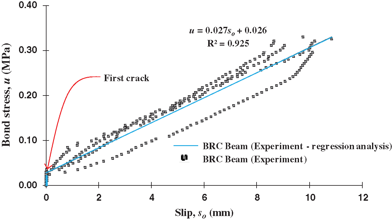
Figure 7: The relationship of bond stress vs. slip of experimental results
3.2 The Validation Local-Slip Using Moment-Curvature and Bond-Stress
The calculation results of bond-stress and local slip uses curvature-moment are shown in Tab. 2, while the Excel program data from the calculation process of curvature-moment, the calculation of bond-stress and local slip at the initial crack, and the calculation of bond-stress and local slip from the second crack until the beam collapses, are each shown on the following links: https://bit.ly/3ltwPEb, https://bit.ly/2UpCQFQ, and https://bit.ly/2Ukj2Uo.
The Excel program can be used directly by inputting material data, cross-sectional geometry data, initial cracking moments until the beam collapses, and the beam cracking process. The use of the Excel program on the links: https://bit.ly/3ltwPEb, https://bit.ly/2UpCQFQ, and https://bit.ly/2Ukj2Uo is carried out by still paying attention to Eqs. (4) to (19) as a control. The second concern is the trial and error calculation process to meet the equilibrium requirements, for example when the first crack occurs, the correction of a neutral line is done based on the known crack moment. Each calculation process in the Excel program is equipped with basic equations and complete information.
Table 2: The data of bond-stress and the local slip of BRC beam from the calculation of the curvature-moment
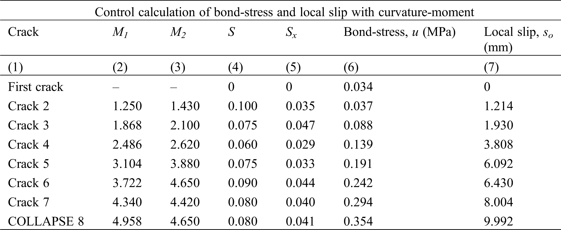
Fig. 8 shows a graph of the relationship of bond-stress vs. local slip of calculation results base on curvature-moment and bond-stress at observation points of cracks and slips. The crack observation of the BRC beam was carried out at eight crack points as shown in Fig. 6 and Tab. 2. The observation points of bond-stress vs. local slip from the initial crack until the collapses beam were analyzed by regression analysis. The coefficient of determination (R2) in the relationship of bond-stress vs. local slip is 0.983, which means that after the initial crack there is an increase in bond-stress by 98% running linearly with an increase in a local slip on the BRC beam.
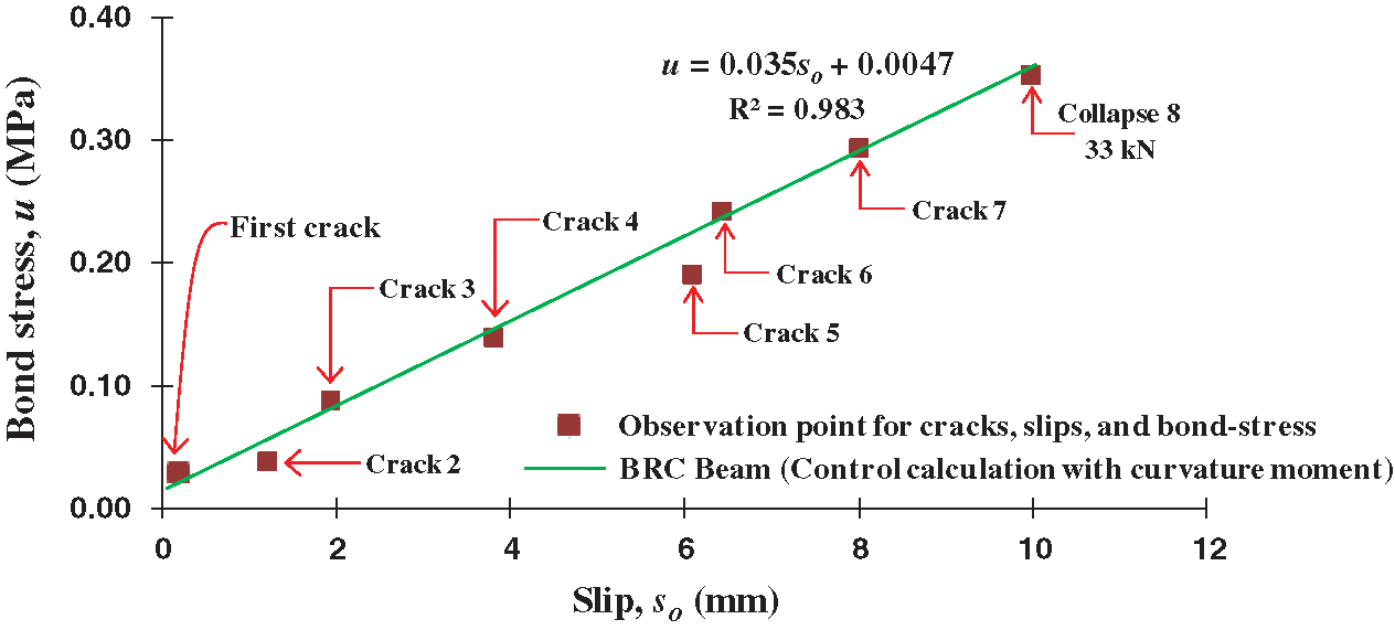
Figure 8: The relationship of bond stress vs. slip from the calculation results of the curvature moment
Fig. 9 shows the relationship of bond-stress vs. local slip of the BRC beam experimental results and the calculation results based on the curvature moment and bond-stress. The two graphs show similarity or coincide. When viewed from the results of the regression analysis with the coefficient of determination parameter, R2 is 0.925 for the experimental results and 0.983 for the analysis results of the curvature-moment and bond-stress. The relationship graph of bond-stress vs. local slip base on curvature-moment shows a difference of approximately 6% from the experimental results. This shows that the amount of observational data such as crack patterns or loading history greatly affects the accuracy of the calculation. While the calculation process is a definite thing in the analysis. However, the experimental results are not fully accurate because the human error factor at the time of testing greatly determines the accuracy of the test data. Calibration of test equipment is also very important to increase the accuracy of the experimental data. Errors caused by human errors usually occur when setting tools and test objects.
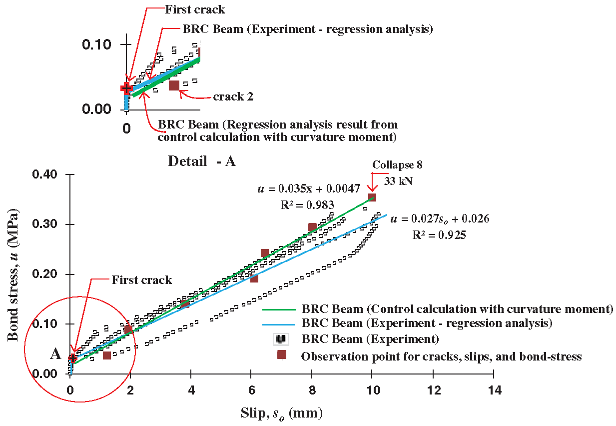
Figure 9: The relationship comparison of bond stress vs. slip from the calculation results of the curvature moment and experiment
Fig. 10 shows the relationship model of bond-stress vs. local slip from the BRC beam of the experimental results, the calculation results based on curvature-moment and bond-stress, the SRC beam of the experimental results [3], and the results of the pull-out test of steel reinforcement [25]. Diab et al. [25] tested the pull-out of steel reinforcement embedded in concrete. The test results show that the relationship of bond-stress vs. slip shows: (a) Friction bond limit of 50%, (b) Proof bond strength of 60%, and (c) Bond-stress at pre-cracking by 70%.
Meanwhile, the BRC beams as shown in Figs. 8 and 9 do not show elastic or plastic limits, so the point of “proof bond strength” and “bond-stress at pre-cracking” become nothing. This is consistent with the stress-strain characteristics of bamboo reinforcement which does not show a clear melting point like steel reinforcement. Thus, from the limit point the “friction bond limit” becomes linear to the limit point “ultimate bond strength”. The value from the initial loading to the “friction bond limit” point is 20% and the value from the “friction bond limit” limit to the “ultimate bond strength” point is estimated to be around 80%.
The relationship of bond-stress vs. local slip for SRC beams shows the limit point of “friction bond limit”, “proof bond strength” and “bond-stress at pre-cracking” [3]. However, at the relationship of bond-stress vs. slip of SRC beam, there is a difference, namely from the limit point of “bond-stress at pre-cracking” to the limit point of “ultimate bond strength” show a horizontal line, as shown in Fig. 10.
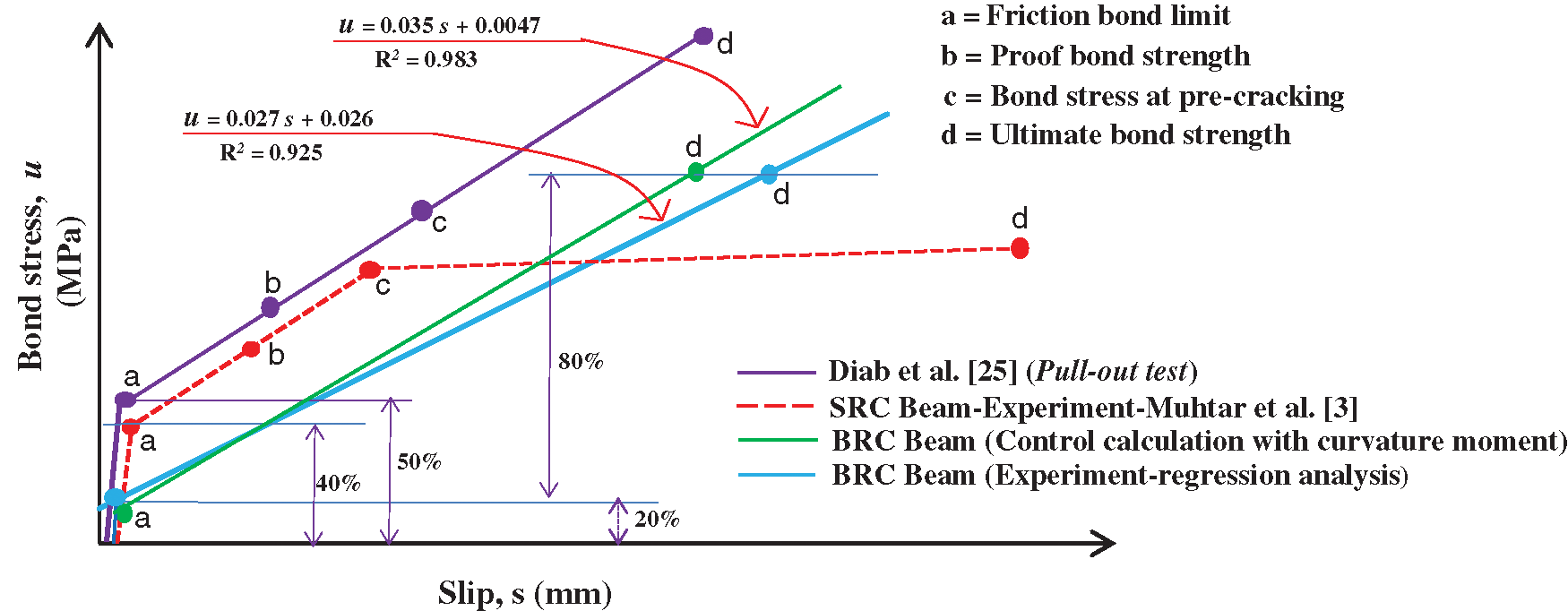
Figure 10: The idealization of the relationship model of bond stress vs. slip of BRC beam
In principle, this calculation method can be used only to control and validate models from experimental data. This method cannot be used for test methods whose purpose is to obtain the data needed for the model, because input data is highly dependent on experimental data. Calculation of the elongation of the concrete to be obtained still requires data from experimental results, such as crack pattern data. However, this method is a solution to establishing the elongation of the concrete and offers an alternative to using a concrete strain-gauge, which is mostly less accurate. And do not rule out the possibility of further research development; this method can predict a model–and evaluate the performance–of structural elements.
Based on the analysis and validation of experimental data using the slip calculation method based on the moment-curvature and bond-stress, several conclusions were obtained including: (1) The relationship of the bond-stress vs. local slip of the experimental results of the BRC beam and the calculation results based on the moment of curvature and bond-stress show similarities or coincide. The difference occurs in approximately 6% of the experimental results. The amount of observational data such as crack patterns, loading history, calibration of test equipment, and readiness of setting tools and specimens greatly affects the value of the accuracy of the calculation; (2) There are differences in the relationship of the bond-stress vs. local slip on the BRC Beams and SRC Beams, the difference is BRC beams do not show elastic or plastic boundaries, so the point of “proof bond strength” and “bond-stress at pre-cracking” become nothing; (3) In a BRC beam, the limit point “friction bond limit” to the limit point “ultimate bond strength” is a linear line. This shows the similarity with the stress-strain relationship behavior of bamboo reinforcement which does not show the melting point clearly; (4) Reading of the elongation of bamboo reinforcement (ebo) through the strain gauge attached to the bamboo reinforcement can still be done even though the concrete has cracked, because when the concrete cracks the bamboo reinforcement does not yield and is still inelastic condition.
This calculation method is useful for controlling, validating, and sensitivity analysis of the relationship model of bond-stress vs. slip from the experimental results, especially the local slip value at certain observation points consisting of concrete elongation (eco) and reinforcement elongation (ebo).
This method is a solution for calculating concrete elongation (eco) and is an alternative to a strain-gauge of concrete, which is largely inaccurate. It does not rule out the possibility for further research development, this method can predict the model and evaluate the performance of structural elements.
Acknowledgement: Funding for this research was fully funded by Research Program, the Directorate of Research and Community Service, the Directorate General of Research and Technology Strengthening and Development of the Ministry of Research, Technology, and Higher Education of the Republic of Indonesia or DRPM of the Republic of Indonesia 2021.
Funding Statement: APC financing entirely by the research program DPRM Republic of Indonesia and LPPM of the University of Muhammadiyah Jember, Indonesia.
Conflicts of Interest: The authors declare that they have no conflicts of interest to report regarding the present study.
1. Javadian, A., Wielopolski, M., Smith, I. F. C., Hebel, D. E. (2016). Bond-behavior study of newly developed bamboo-composite reinforcement in concrete. Construction and Building Materials, 122(5), 110–117. DOI 10.1016/j.conbuildmat.2016.06.084. [Google Scholar] [CrossRef]
2. Rahman, M. M., Rashid, M. H., Hossain, M. A., Hasan, M. T., Hasan, M. K. (2011). Performance evaluation of bamboo reinforced concrete beam. International Journal of Engineering & Technology, 11(04), 113–118. [Google Scholar]
3. Muhtar, Dewi, S. M., Wisnumurti, Munawir, A. (2019). Enhancing bamboo reinforcement using a hose-clamp to increase bond-stress and slip resistance. Journal of Building Engineering, 26, 100896. DOI 10.1016/j.jobe.2019.100896. [Google Scholar] [CrossRef]
4. Muhtar (2019). Experimental data from strengthening bamboo reinforcement using adhesives and hose-clamps. Data in Brief, 27, 104827. [Google Scholar]
5. Ghavami, K. (2005). Bamboo as reinforcement in structural concrete elements. Cement and Concrete Composites, 27(6), 637–649. DOI 10.1016/j.cemconcomp.2004.06.002. [Google Scholar] [CrossRef]
6. Agarwal, A., Nanda, B., Maity, D. (2014). Experimental investigation on chemically treated bamboo reinforced concrete beams and columns. Construction and Building Materials, 71(2), 610–617. DOI 10.1016/j.conbuildmat.2014.09.011. [Google Scholar] [CrossRef]
7. Sabnani, C., Latkar, M., Sharma, U. (2013). Can bamboo replace Steel as reinforcement in concrete, for the key structural elements in a low-cost house, designed for the urban poor? International Journal of Chemical, Environmental & Biological Sciences, 1, 257–262. [Google Scholar]
8. Puri, V., Chakrabortty, P., Anand, S., Majumdar, S. (2017). Bamboo reinforced prefabricated wall panels for low-cost housing. Journal of Building Engineering, 9, 52–59. DOI 10.1016/j.jobe.2016.11.010. [Google Scholar] [CrossRef]
9. Muhtar, Dewi, S. M., Wisnumurti, Munawir, A. (2018). The stiffness and cracked pattern of bamboo reinforced concrete beams using a hose clamp. International Journal of Civil Engineering and Technology, 9(8), 273–284. [Google Scholar]
10. Muhtar (2020). Cracked pattern of bamboo reinforced concrete beams using double reinforcement with the strengthening on tensile reinforcement. International Journal of Engineering Research and Technology, 13(3), 608–612. [Google Scholar]
11. Ikponmwosa, E., Fapohunda, C., Kolajo, O., Eyo, O. (2017). Structural behavior of bamboo-reinforced foamed concrete slab containing polyvinyl wastes (PW) as partial replacement of fine aggregate. Journal of King Saud University–Engineering Sciences, 29(4), 348–355. DOI 10.1016/j.jksues.2015.06.005. [Google Scholar] [CrossRef]
12. Kumar, P. V., Vasugi, V. (2014). Study on mechanical strength of bamboo reinforced concrete beams. International Journal of Advances in Science Engineering and Technology, 2(3), 103–105. [Google Scholar]
13. Nindyawati, Dewi, S. M., Soehardjono, A. (2013). The comparison between pull-out test and beam bending test to the bond strength of bamboo reinforcement in light weight concrete. International Journal of Engineering Research and Applications, 3(1), 1497–1500. [Google Scholar]
14. Leelatanon, S., Srivaro, S., Matan, N. (2010). Compressive strength and ductility of short concrete columns reinforced by bamboo. Songklanakarin Journal of Science and Technology, 32(4), 419–424. [Google Scholar]
15. Sevalia, J. K., Siddhpura, N. B., Shah, D. B., Kapadia, J. V., Agrawal, C. S. (2013). Performance evaluation of axially loaded element using bamboo as reinforcement. International Journal of Engineering and Advanced Technology, 2(4), 413–415. [Google Scholar]
16. Terai, M., Minami, K. (2012). Research and development on bamboo reinforced concrete structure. World Conferences on Earthquake Engineering, 2012, 1–10. [Google Scholar]
17. Qaiser, S., Hameed, A., Alyousef, R., Aslam, F., Alabduljabbar, H. (2020). Flexural strength improvement in bamboo reinforced concrete beams subjected to pure bending. Journal of Building Engineering, 31(2), 101289. DOI 10.1016/j.jobe.2020.101289. [Google Scholar] [CrossRef]
18. Ahmad, M. S. (2016). Bond in flexure: A review of ACI CODE 408R. International Journal of Advanced Technology in Engineering and Science, 4(2), 79–84. [Google Scholar]
19. Lee, Y., Phares, B. (2015). Bond strength and development length of galvanized reinforcing steel. International Journal of Civil and Structural Engineering Research, 3, 311–317. [Google Scholar]
20. Budi, A. S., Rahmadi, A. P., Rismunarsi, E. (2016). Experimental study of flexural capacity on bamboo ori strip notched v reinforced concrete beams. International Conference on Engineering, Science and Nanotechnology 2016 (ICESNANO 2016), pp. 1–7. DOI 10.1063/1.4968305. [Google Scholar] [CrossRef]
21. Mali, P. R., Datta, D. (2020). Experimental evaluation of bamboo reinforced concrete beams. Journal of Building Engineering, 28(7), 101071. DOI 10.1016/j.jobe.2019.101071. [Google Scholar] [CrossRef]
22. Dey, A., Chetia, N. (2018). Experimental study of Bamboo Reinforced Concrete beams having various frictional properties. Materials Today, 5(1), 436–444. DOI 10.1016/j.matpr.2017.11.103. [Google Scholar] [CrossRef]
23. Dewi, S. M., Nuralinah, D. (2017). Recent research on bamboo reinforced concrete. MATEC Web of Conferences, Bangka Island, Indonesia, 2016; EDP Sciences: Les Ulis, France, 2017. [Google Scholar]
24. Archila, H., Kaminski, S., Trujillo, D., Zea, E., Harries, K. A. et al. (2018). Bamboo reinforced concrete: A critical review. Materials and Structures, 51(4), 42. DOI 10.1617/s11527-018-1228-6. [Google Scholar] [CrossRef]
25. Diab, A. M., Elyamany, H. E., Hussein, M. A., Al Ashy, H. M. (2014). Bond-behavior, and assessment of design ultimate bond stress of normal and high strength concrete. Alexandria Engineering Journal, 53(2), 355–371. DOI 10.1016/j.aej.2014.03.012. [Google Scholar] [CrossRef]
26. Siempu, R., Pancharthi, R. K. (2018). A Study on the parameters influencing flexural bond stress in reinforced concrete. Structures, 16(13), 198–207. DOI 10.1016/j.istruc.2018.09.006. [Google Scholar] [CrossRef]
27. Tang, C., Cheng, C. (2020). Modeling local bond stress-slip relationships of reinforcing bars embedded in concrete with different strengths. Materials, 13(17), 3701. DOI 10.3390/ma13173701. [Google Scholar] [CrossRef]
28. Wang, Z., Zhao, J., Liu, T. (2019). Bond-slip model for horizontal reinforcing bars in reinforced brick masonry. Engineering Structures, 201(3), 109770. DOI 10.1016/j.engstruct.2019.109770. [Google Scholar] [CrossRef]
29. Wang, Y. J., Wu, Z. M., Zheng, J. J., Yu, R. C., Liu, Y. (2019). Analytical method for crack propagation process of lightly reinforced concrete beams considering bond-slip behaviour. Engineering Fracture Mechanics, 220, 106654. DOI 10.1016/j.engfracmech.2019.106654. [Google Scholar] [CrossRef]
30. Jacques, E., Saatcioglu, M. (2019). High strain rate bond characteristics of reinforced concrete beam-ends. International Journal of Impact Engineering, 130(85), 192–202. DOI 10.1016/j.ijimpeng.2019.04.012. [Google Scholar] [CrossRef]
31. Lin, X., Zhang, Y. X. (2013). Bond-slip behavior of FRP-reinforced concrete beams. Construction and Building Materials, 44, 110–117. DOI 10.1016/j.conbuildmat.2013.03.023. [Google Scholar] [CrossRef]
32. Piyasena, R. (2002). Crack spacing, crack width and tension stiffening effect in reinforced concrete beams and one-way slabs (Ph.D. Thesis). Queensland Australia: Griffith University. [Google Scholar]
33. ASTM C 09 (2002). Standard test method for flexural strength of concrete (using simple beam with third-point loading). West Con shohocken: ASTM International. [Google Scholar]
34. Muhtar, Gunasti, A., Dewi, I. C., Dasuki, M., Ariyani, S. et al. (2020). The prediction of stiffness of bamboo-reinforced concrete beams using experiment data and artificial neural networks (ANNs). Crystals, 10(9), 757. DOI 10.3390/cryst10090757. [Google Scholar] [CrossRef]
35. Park, R., Paulay, T. (1975). Reinforced concrete structures, pp. 1–769. New York: John Wiley & Sons. [Google Scholar]
 | This work is licensed under a Creative Commons Attribution 4.0 International License, which permits unrestricted use, distribution, and reproduction in any medium, provided the original work is properly cited. |