| Structural Durability & Health Monitoring |
DOI: 10.32604/sdhm.2022.022082
ARTICLE
Identification of Internal Damage in Circular Cylinders through Laser Scanning of Vibrating Surfaces
1Department of Engineering Mechanics, Hohai University, Nanjing, 210098, China
2Department of Basic Education, Rocket Force University of Engineering, Xi’an, 710025, China
3Jiangsu Province Wind Power Structural Engineering Research Center, Hohai University, Nanjing, 210098, China
4Jiangsu Hongyuan Science and Technology Engineering Co., Ltd., Changzhou, 213162, China
5Jiangsu Zhongji Engineering Technology Research Co., Ltd., Nantong, 226001, China
6College of Civil and Architecture Engineering, Chuzhou University, Chuzhou, 23900, China
7Department of Technical Sciences, State University of Novi Pazar, Novi Pazar, 36300, Serbia
*Corresponding Author: Wei Xu. Email: wxu@hhu.edu.cn
Received: 20 February 2022; Accepted: 25 February 2022
Abstract: With the aid of non-contact measurements of vibrating surfaces through laser scanning, operating deflection shapes (ODSs) with high spatial resolutions can be used to graphically characterize damage in plane structures. Although numerous damage identification approaches relying on laser-measured ODSs have been developed for plate-type structures, they cannot be directly applied to circular cylinders due to the gap between equations of motions of plates and circular cylinders. To fill this gap, a novel approach is proposed in this study for damage identification of circular cylinders. Damage-induced discontinuities of the derivatives of ODSs can be used to graphically manifest the occurrence of the damage, and characterize the location and size of the damage. The approach is experimentally validated on a specimen of the circular cylinder component, whose out-of-plane ODSs in an inspection region are acquired through laser scanning using a scanning laser vibrometer. The results suggest that the occurrence, location, and size of the internal damage of the circular cylinder can be identified.
Keywords: Internal damage identification; circular cylinder; non-contact vibration measurement; laser scanning; operating deflection shape
Many structural components one can encounter in real applications, such as wind turbine towers, can be simplified as circular cylinders [1]. With the motivation of ensuring the integrity and safety of cylinder-type structures, nondestructive testing (NDT) techniques relying on the electrical resistance [2], thermography [3], electro-mechanical impedance [4], laser ultrasonic [5], strain [6], etc., have been widely applied.
Besides the existing NDT techniques, vibration approaches have been rapidly developed in the past decade for damage detection in circular cylinders [7–10]. Structural damage can induce local reduction of stiffness, leading to changes in structural dynamic characteristics; conversely, through such changes the damage can be detected [11]. Amongst vibration approaches, derivatives of operating deflection shapes (ODSs) with respect to spatial coordinates can be used for damage identification of circular cylinders because ODSs contain the spatial information of the damage. However, spatial distributions of the existing wired sensors are limited and unable to provide ODSs with high spatial resolutions. An alternative solution is to evaluate pointwise damage indices by moving the excitation throughout measurement grids like other NDT techniques [8]. With the aid of non-contact measurements of vibrating surfaces through laser scanning, ODSs of plane structures, e.g., plates, shells, and cylinders, can be densely measured with high spatial resolutions [12,13]. In the past decade, most studies are focused on plate-type structures. Qiao et al. [14] used curvature mode shapes (CMSs) to detect delamination in composite laminated plates. Xu et al. [15–17] integrated CMSs with wavelet transform for the damage identification of plates. Using the Fourier spectral method over the conventional central difference operator, Yang et al. [18,19] proposed the Fourier spectral CMS to detect damage in composite plates. To extract damage-induced local features for damage detection of plate-type structures, Cao et al. [20,21] introduced the principal components analysis into CMSs. Xu et al. [22,23] and Chen et al. [24–26] extracted local anomalies in differences between measured and reconstructed CMSs, by which damage in plate-type structures can be identified. Cao et al. [27] used derivatives of shear strains for damage detection of plate-type structures. Furthermore, Xu et al. [28] formulated the concept of twist derivative to detect and locate damage in plate-type structures. The concept of “pseudo-force/excitation” was recently proposed by regarding the damage effect as an equivalent force applied on structural elements bearing damage [29–40]. The pseudo-forces of plates are formulated using out-of-plane ODSs and their fourth-order derivatives.
Although numerous approaches relying on laser-measured ODSs have been developed for damage identification of plate-type structures, they cannot be directly applied to circular cylinders due to the gap between equations of motions of plates and circular cylinders. To fill this gap, a novel approach is proposed in this study for damage identification of circular cylinders. In particular, starting from the equation of motion of a circular cylinder element, three damage indices (DIs) are formulated using derivatives of out-of-plane ODSs of the circular cylinder. Damage-induced discontinuities of the derivatives of ODSs can be used to graphically manifest the occurrence of the damage and characterize the location and size of the damage. Through the proposed approach, the occurrence, location, and size of the internal damage of the circular cylinder can be identified.
The rest of the paper is organized as follows. Section 2 proposes a novel approach for damage identification of circular cylinders using laser-measured ODSs. Section 3 experimentally validates the approach on a specimen of circular cylinder which is a component of a wind turbine tower model. The specimen is excited by harmonic excitations using an electromagnetic shaker, and its out-of-plane ODSs in an inspection region are acquired through laser scanning using a scanning laser vibrometer (SLV). Section 4 presents concluding remarks.
2 Damage-Caused Singularity in ODSs
Considering a circular cylinder subject to single-tone harmonic excitations in the transverse direction, at some frequencies it only has radial displacements but does not have circumferential and longitudinal displacements. The equation of out-of-plane motion of the circular cylinder can be written as [1]
where
Assume that the steady-state displacement
For elements in the circular cylinder that bear no transverse load, i.e.,
where
Considering a local damage whose damage region is denoted as
For numerical evaluation, DIs in Eq. (5) can be calculated by the finite difference method:
with
3 Identification of Internal Damage in a Circular Cylinder Using Laser-Measured ODSs
The capacity of the approach of damage identification is experimentally validated on a specimen of circlular cylinder, whose out-of-plane ODSs in an inspection region are acquired through laser scanning using an SLV. The experiment was implemented in the Structural Dynamics Laboratory at Hohai University.
3.1 Experimental Specimen and Setup
A circular cylinder made of steel Q235B is taken as an experimental specimen as shown in Fig. 1, which is a component of a wind turbine tower model. Considering environmental effects on structural surfaces after long-term service, the surfaces of the specimen have rusted before the experiment. The elastic module and density of the cylinder are 206 Gpa and 7850 Kgm−3, respectively. The height and external diameter of the cylinder are both 300 mm. The thickness of the cylinder is 8 mm. The lower circular edge of the cylinder is welded with a rectangular steel plate as the foundation of the cylinder, which is of thickness 10 mm and fixed by bolts on the vibration isolation platform at its four corners. The size of the rectangular measurement region of the cylinder is 160 mm × 160 mm, which spans from 70 to 230 mm from the foundation. In the measurement region, 21 × 21 patches of reflection tapes are uniformly distributed for laser scanning measurement, as shown in Fig. 1a. Internal damage (marked in a red circle) was manufactured by drilling to form a conical pit on the internal surface of the cylinder, as shown in Figs. 1b and 1c. The diameter and depth of the conical pit are 20 and 4 mm, respectively. In dimensionless coordinates of the measurement region, the damage is centered at
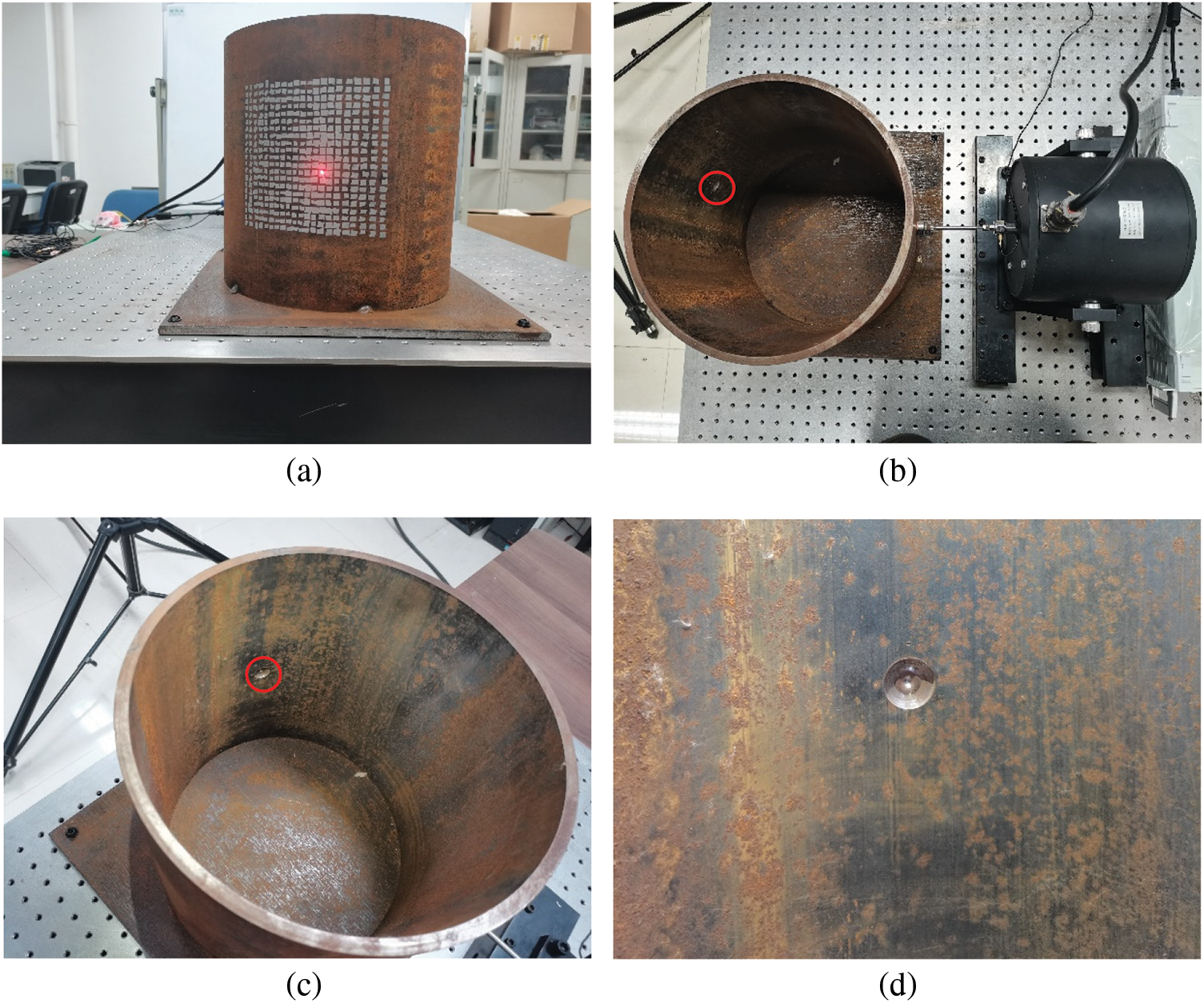
Figure 1: Experimental specimen: A circular cylinder with internal damage
The experimental setup is shown in Fig. 2, consisting of an actuation system and a sensing system (Fig. 2a). The actuation system consists of an arbitrary waveform generator (DH testing-DH1301, shown in Fig. 2b), a power amplifier (DH testing-DH5872, as shown in Fig. 2c), and an electromagnetic shaker (DH testing-DH40200, as shown in Fig. 2d). The waveforms generated by the arbitrary waveform generator are amplified by the power amplifier and then input into the electromagnetic shaker to produce forces. The electromagnetic shaker is attached to the external surface of the cylinder to excite it in the radial direction. The equipment of the sensing system is an SLV (Polytec-PSV 400), which consists of a scanning laser head (Fig. 2a) and a controller (Fig. 2e). The SLV is used to measure the velocities of the circular cylinder at the measurement points. The grid layout of the measurement points that covers the damage region is shown in Fig. 3.
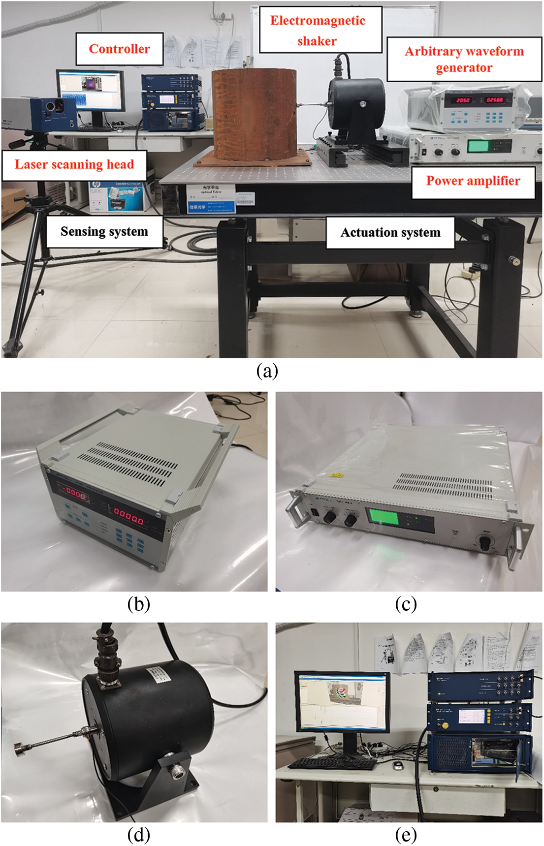
Figure 2: Experimental setup: Actuation and sensing systems
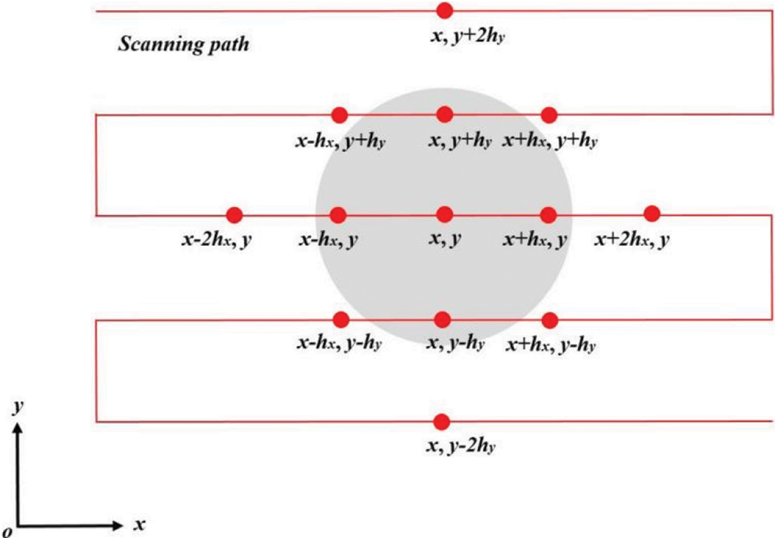
Figure 3: Grid layout of the measurement points covering the damage region
The modal analysis has been first implemented to acquire the natural frequencies of the circular cylinder. The voltage set in the arbitrary waveform generator is 2 V and amplified to 15 V in the power amplifier. The harmonic excitation periodically sweeps from 0 to 1000 Hz in 2.5 s. Simultaneously, the SLV is used to measure the velocity response of the cylinder at the upper right corner of the measurement region. The number of fast Fourier transform (FFT) lines is 6400, and the sampling frequency is 2.56 kHz. The time history of the velocity response is shown in Fig. 4a, and its frequency spectrum is obtained by FFT and shown in Fig. 4b.
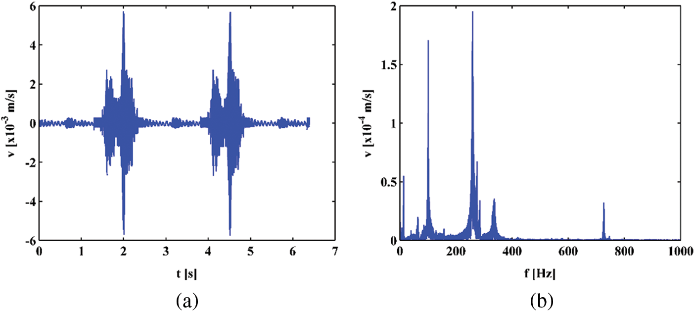
Figure 4: (a) Time history of the velocity response and (b) its frequency spectrum
The cylinder is excited at its resonances in this study to obtain large magnitudes for high signal-to-noise ratios. From the frequency spectrum of the cylinder (Fig. 4b), its natural frequencies of 12.50, 63.75, 100.63, and 335.94 Hz are selected as excitation frequencies. When the circular cylinder vibrates subject to the harmonic excitations, the SLV scans the measurement region pointwisely. The steady-state velocity responses at 12.50, 63.75, 100.63, and 335.94 Hz are acquired, which constitute the corresponding ODSs as shown in Figs. 5a–5d, respectively. The ODSs of the circular cylinder approximate its corresponding mode shapes for this lightly damped system. The number of FFT lines is 3200, and the sampling frequency is 2.56 kHz. Note that the measured ODSs are extended from 21 × 21 to 101 × 101 by cubic interpolation for higher spatial resolution.
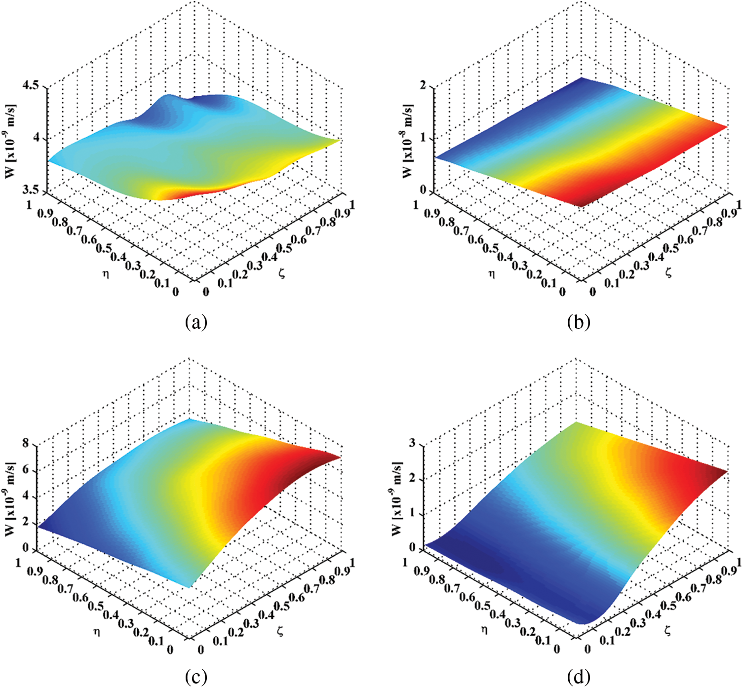
Figure 5: ODSs for natural frequencies of (a) 12.50, (b) 63.75, (c) 100.63, and (d) 335.94 Hz
The
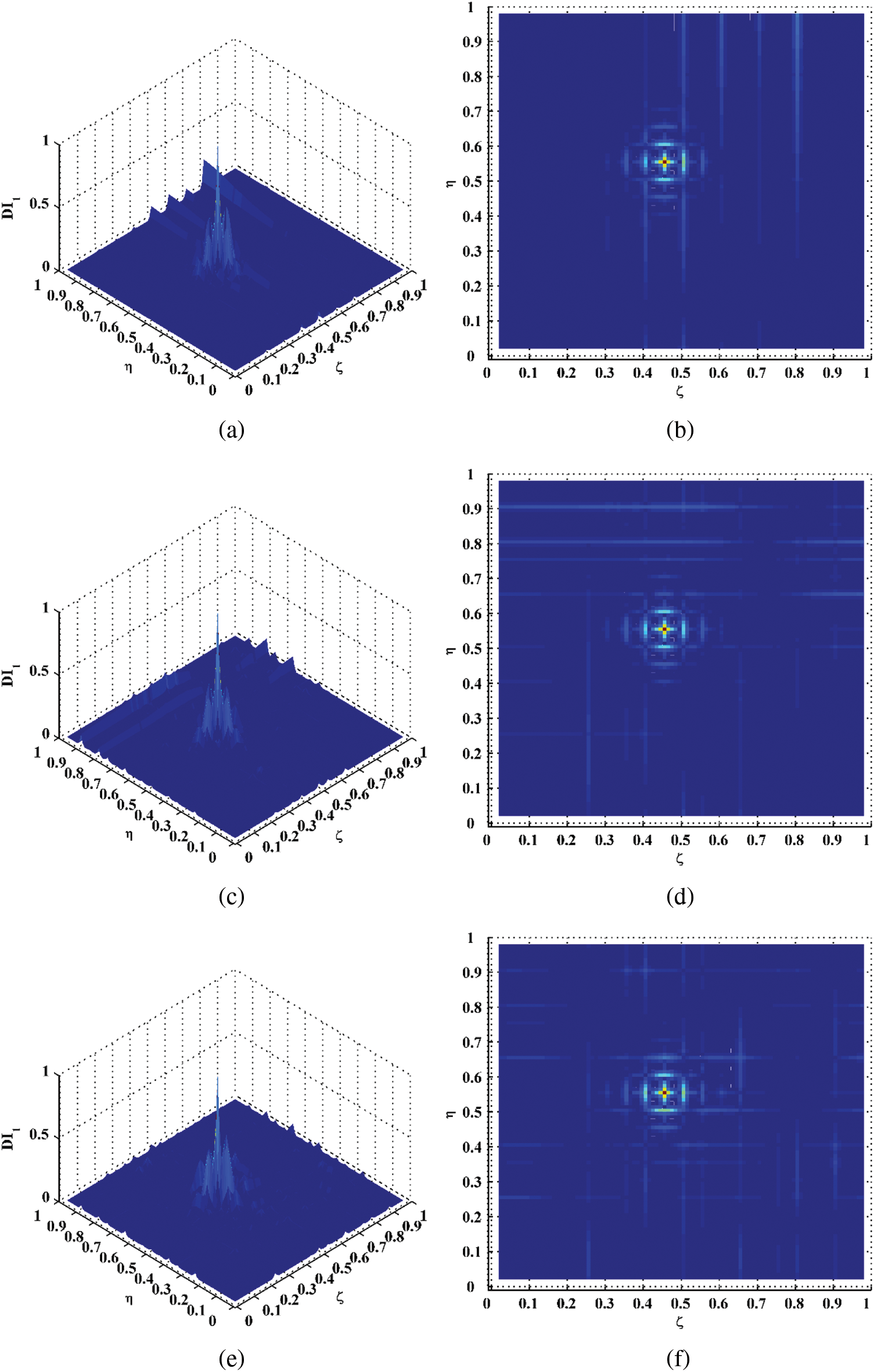
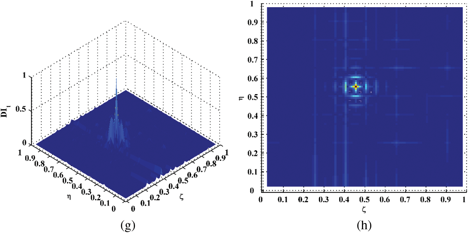
Figure 6: DI1 for natural frequencies of (a) 12.50, (c) 63.75, (e) 100.63, and (g) 335.94 Hz and their planforms (b), (d), (f), and (h)
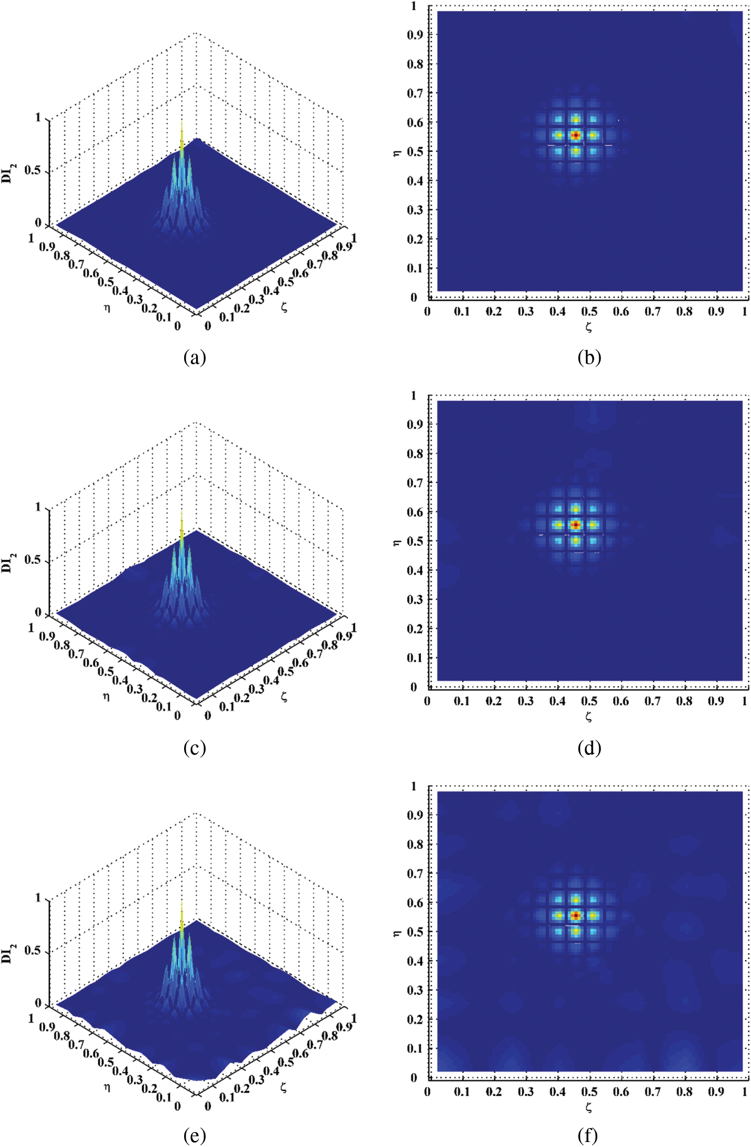
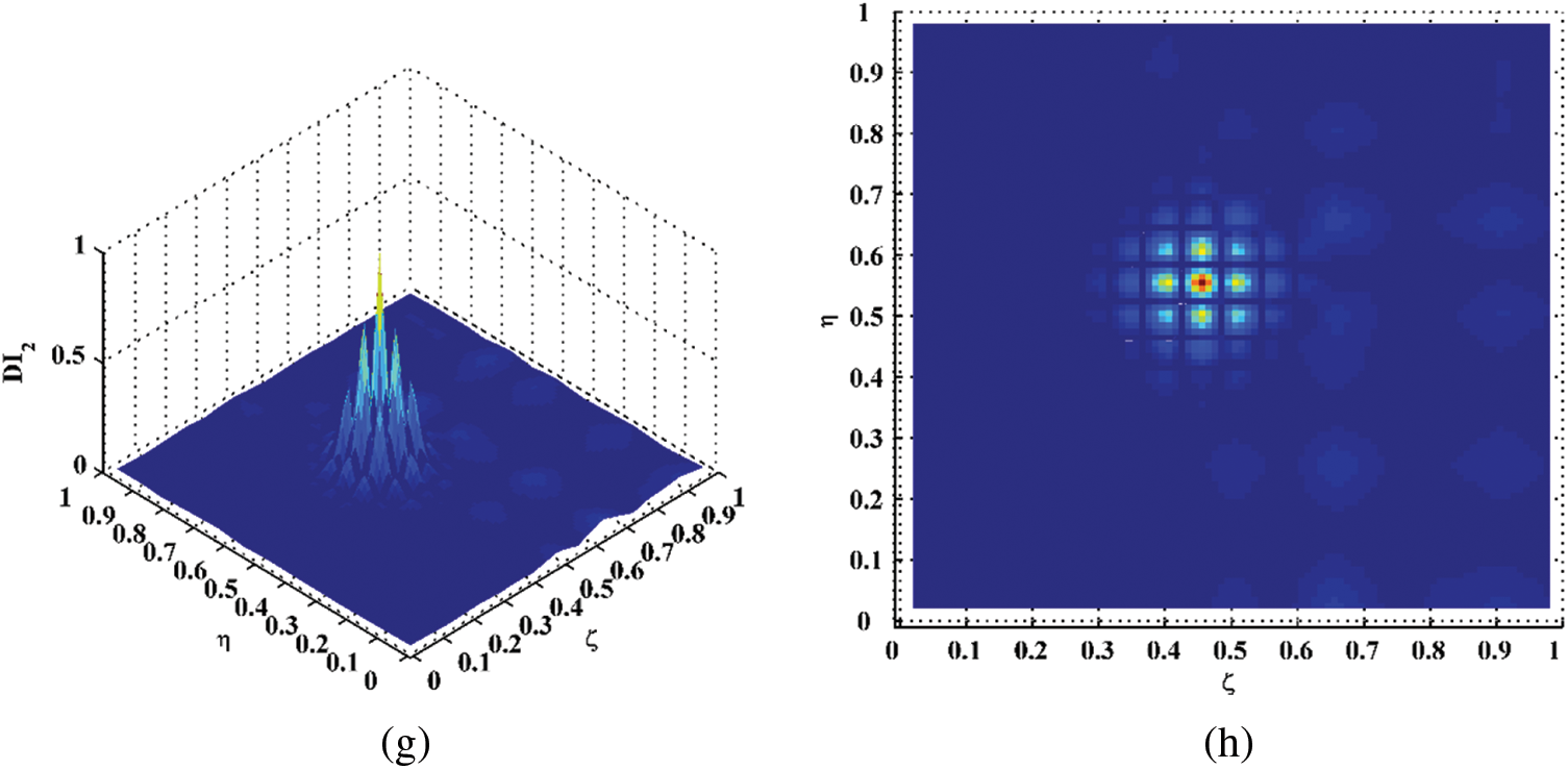
Figure 7: DI2 for natural frequencies of (a) 12.50, (c) 63.75, (e) 100.63, and (g) 335.94 Hz and their planforms (b), (d), (f), and (h)
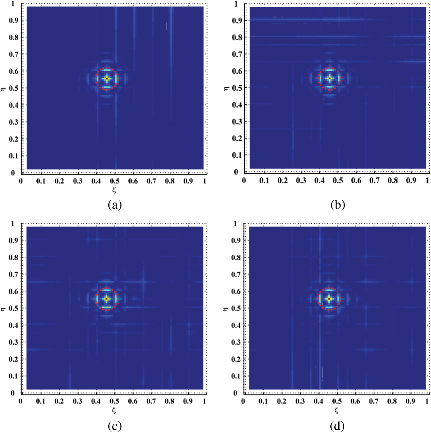
Figure 8: Planforms of the DI3 for natural frequencies of (a) 12.50, (b) 63.75, (c) 100.63, and (d) 335.94 Hz (the outlines of the actual damage region are marked in red dashed circles)
Furthermore, to suppress the interferences at undamaged locations of the
By comparing the
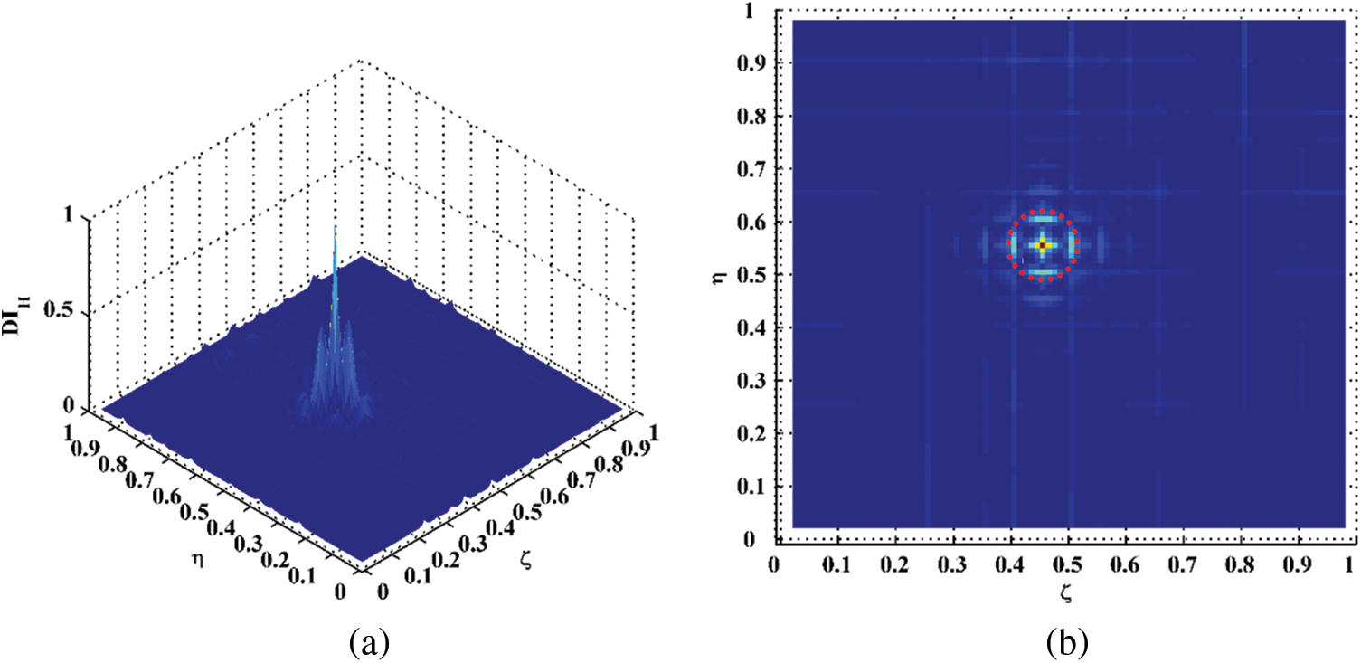
Figure 9: (a) Hybrid DI and its (b) planform
The experimental results validate that internal damage identification of circular cylinders can be achieved by the approach proposed in this study, by which the occurrence, location, and size of the damage can be graphically characterized. The proposed approach for damage identification in circular cylinders is baseline-free, which means that the material or structural parameters can be absent. Only out-of-plane ODSs of circular cylinders in inspection regions are needed to be measured through laser scanning, from which the DIs can be calculated using the finite difference method. Nevertheless, it is assumed the cylinders under inspection only have radial displacements but do not have circumferential and longitudinal displacements.
Due to the gap between equations of motions of plates and circular cylinders, approaches for damage identification of plate-type structures relying on laser-measured ODSs cannot be directly applied to circular cylinders. To fill this gap, a novel approach is proposed in this study for damage identification of circular cylinders. The approach is experimentally validated on a circular cylinder component, whose out-of-plane ODSs in the inspection region are acquired through laser scanning using an SLV. Through the proposed approach the occurrence, location, and size of the internal damage of the circular cylinder can be identified. Some conclusions are as follows:
(1) Starting from the equation of motion of a circular cylinder element, three DIs, i.e.,
(2) The experimental results suggest that the
(3) The hybrid DI
(4) The proposed approach for internal damage identification of circular cylinders is baseline-free, which means that the material or structural parameters can be absent. Only out-of-plane ODSs of circular cylinders in inspection regions are needed to be measured through laser scanning, from which the DIs can be calculated using the finite difference method. Nevertheless, it is assumed the cylinders under inspection only have radial displacements but do not have circumferential and longitudinal displacements.
Funding Statement: The authors are grateful for the supports from the Changzhou Policy Guidance Plan-International Science and Technology Cooperation (No. CZ20200003), the Anhui International Joint Research Center of Data Diagnosis and Smart Maintenance on Bridge Structures (No. 2021AHGHYB01), the Nantong Science and Technology Opening Cooperation Project in 2021 (No. BW2021001), and the Key R&D Project of Anhui Science and Technology Department (202004b11020026).
Conflicts of Interest: The authors declare no conflict of interest. The funders had no role in the design of the study; in the collection, analyses, or interpretation of data; in the writing of the manuscript, or in the decision to publish the results.
1. Leissa, A. W., Qatu, M. S. (2011). Vibration of continuous systems. New York: McGraw Hill. [Google Scholar]
2. Wen, J., Xia, Z., Choy, F. (2011). Damage detection of carbon fiber reinforced polymer composites via electrical resistance measurement. Composites Part B: Engineering, 42(1), 77–86. DOI 10.1016/j.compositesb.2010.08.005. [Google Scholar] [CrossRef]
3. Zalamedaa, J. N., Winfreea, W. P., Seebob, J. P., Johnston, P. H. (2011). Thermography inspection for detection and tracking of composite cylinder damage during load testing. AIP Conference Proceedings, 450, 1335. DOI 10.1063/1.3591887. [Google Scholar] [CrossRef]
4. Na, S., Lee, H. K. (2012). Resonant frequency range utilized electro-mechanical impedance method for damage detection performance enhancement on composite structures. Composite Structures, 94(8), 2383–2389. DOI 10.1016/j.compstruct.2012.02.022. [Google Scholar] [CrossRef]
5. Ji, M., He, J., Lai, Y., Xiao, R. (2015). Application of laser ultrasonic visualization inspection in the detection of cylinder sleeve. International Conference on Mechatronics, Electronic, Industrial and Control Engineering, Shenyang, China. [Google Scholar]
6. Mercuri, A., Fanelli, P., Ubertini, S., Falcucci, G., Biscarini, C. (2021). Effect of strain measurement layout on damage detection and localization in a free falling compliant cylinder impacting a water surface. Fluids, 6(2), 58. DOI 10.3390/fluids6020058. [Google Scholar] [CrossRef]
7. Rucka, M., Wilde, K. (2010). Neuro-wavelet damage detection technique in beam, plate and shell structures with experimental validation. Journal of Theoretical and Applied Mechanics, 48, 579–604. [Google Scholar]
8. Hu, H., Wu, C., Lu, W. J. (2011). Damage detection of circular hollow cylinder using modal strain energy and scanning damage index methods. Computers and Structures, 89(1–2), 149–160. DOI 10.1016/j.compstruc.2010.08.011. [Google Scholar] [CrossRef]
9. Taajobian, M., Mohammadzaheri, M., Doustmohammadi, M., Amouzadeh, A., Emadi, M. (2018). Fault diagnosis of an automobile cylinder head using low frequency vibrational data. Journal of Mechanical Science and Technology, 32(7), 3037–3045. DOI 10.1007/s12206-018-0606-x. [Google Scholar] [CrossRef]
10. Miller, B., Ziemianski, L. (2021). Detection of material degradation of a composite cylinder using mode shapes and convolutional neural networks. Materials, 14(21), 6686. DOI 10.3390/ma14216686. [Google Scholar] [CrossRef]
11. Fan, W., Qiao, P. (2011). Vibration-based damage identification methods: A review and comparative study. Structural Health Monitoring, 10(1), 83–111. DOI 10.1177/1475921710365419. [Google Scholar] [CrossRef]
12. Chen, D. M., Xu, Y. F., Zhu, W. D. (2018). Non-model-based multiple damage identification of beams by a continuously scanning laser Doppler vibrometer system. Measurement, 115(1), 185–196. DOI 10.1016/j.measurement.2017.09.017. [Google Scholar] [CrossRef]
13. Cao, S., Lu, Z., Wang, D., Xu, C. (2021). Robust multi-damage localization in plate-type structures via adaptive denoising and data fusion based on full-field vibration measurements. Measurement, 178, 109393. DOI 10.1016/j.measurement.2021.109393. [Google Scholar] [CrossRef]
14. Qiao, P., Lu, K., Lestari, W., Wang, J. (2007). Curvature mode shape-based damage detection in composite laminated plates. Composite Structures, 80(3), 409–428. DOI 10.1016/j.compstruct.2006.05.026. [Google Scholar] [CrossRef]
15. Xu, W., Cao, M., Ostachowicz, W., Radzienski, M., Xia, N. (2015). Two-dimensional curvature mode shape method based on wavelets and Teager energy for damage detection in plates. Journal of Sound and Vibration, 347(6), 266–278. DOI 10.1016/j.jsv.2015.02.038. [Google Scholar] [CrossRef]
16. Xu, W., Cao, M., Li, X., Radzienski, M., Ostachowicz, W. et al. (2017). Delamination monitoring in CFRP laminated plates under noisy conditions using complex-wavelet 2D curvature mode shapes. Smart Materials and Structures, 26(10), 104008. DOI 10.1088/1361-665X/aa8316. [Google Scholar] [CrossRef]
17. Xu, W., Ding, K., Liu, J., Cao, M., Radzieński, M. et al. (2019). Non-uniform crack identification in plate-like structures using wavelet 2D modal curvature under noisy conditions. Mechanical Systems and Signal Processing, 126(6), 469–489. DOI 10.1016/j.ymssp.2019.01.047. [Google Scholar] [CrossRef]
18. Yang, Z. B., Radzienski, M., Kudela, P., Ostachowicz, W. (2016). Two-dimensional modal curvature estimation via Fourier spectral method for damage detection. Composite Structures, 148, 155–167. DOI 10.1016/j.compstruct.2016.04.001. [Google Scholar] [CrossRef]
19. Yang, Z. B., Radzienski, M., Kudela, P., Ostachowicz, W. (2017). Two-dimensional Chebyshev pseudo spectral modal curvature and its application in damage detection for composite plates. Composite Structures, 168, 372–383. DOI 10.1016/j.compstruct.2017.02.066. [Google Scholar] [CrossRef]
20. Cao, S., Ouyang, H., Cheng, L. (2019). Baseline-free multidamage identification in plate-like structures by using multiscale approach and low-rank modelling. Structural Control and Health Monitoring, 26(2), e2293. DOI 10.1002/stc.2293. [Google Scholar] [CrossRef]
21. Cao, S., Ouyang, H., Cheng, L. (2019). Baseline-free adaptive damage localization of plate-type structures by using robust PCA and Gaussian smoothing. Mechanical Systems and Signal Processing, 122, 232–246. DOI 10.1016/j.ymssp.2018.12.017. [Google Scholar] [CrossRef]
22. Xu, Y. F., Zhu, W. D. (2017). Non-model-based damage identification of plates using measured mode shapes. Structural Health Monitoring, 16(1), 3–23. DOI 10.1177/1475921716655974. [Google Scholar] [CrossRef]
23. Xu, Y. F., Zhu, W. D., Smith, S. A. (2017). Non-model-based damage identification of plates using principal, mean and Gaussian curvature mode shapes. Journal of Sound and Vibration, 400(6), 626–659. DOI 10.1016/j.jsv.2017.03.030. [Google Scholar] [CrossRef]
24. Chen, D. M., Xu, Y. F., Zhu, W. D. (2017). Experimental investigation of notch-type damage identification with a curvature-based method by using a continuously scanning laser Doppler vibrometer system. Journal of Nondestructive Evaluation, 36(2), 38. DOI 10.1007/s10921-017-0418-4. [Google Scholar] [CrossRef]
25. Chen, D. M., Xu, Y. F., Zhu, W. D. (2018). Identification of damage in plates using full-field measurement with a continuously scanning laser Doppler vibrometer system. Journal of Sound and Vibration, 422(1), 542–567. DOI 10.1016/j.jsv.2018.01.005. [Google Scholar] [CrossRef]
26. Chen, D. M., Xu, Y. F., Zhu, W. D. (2018). Non-model-based identification of delamination in laminated composite plates using a continuously scanning laser Doppler vibrometer system. Journal of Vibration and Acoustics, 140(4), 041001. DOI 10.1115/1.4038734. [Google Scholar] [CrossRef]
27. Cao, M. S., Ostachowicz, W., Radzienski, M., Xu, W. (2013). Multiscale shear-strain gradient for detecting delamination in composite laminates. Applied Physics Letters, 103(10), 101910. DOI 10.1063/1.4820182. [Google Scholar] [CrossRef]
28. Xu, W., Zhu, W. D., Cao, M. S., Wu, H., Zhu, R. H. (2020). A novel damage index for damage detection and localization of plate-type structures using twist derivatives of laser-measured mode shapes. Journal of Sound and Vibration, 481(8), 115448. DOI 10.1016/j.jsv.2020.115448. [Google Scholar] [CrossRef]
29. Xu, H., Cheng, L., Su, Z., Guyader, J. L. (2011). Identification of structural damage based on locally perturbed dynamic equilibrium with an application to beam component. Journal of Sound and Vibration, 330(24), 5963–5981. DOI 10.1016/j.jsv.2011.07.028. [Google Scholar] [CrossRef]
30. Cao, M., Cheng, L., Su, Z., Xu, H. (2012). A multi-scale pseudo-force model in wavelet domain for identification of damage in structural components. Mechanical Systems and Signal Processing, 28(2), 638–659. DOI 10.1016/j.ymssp.2011.11.011. [Google Scholar] [CrossRef]
31. Cao, M., Su, Z., Cheng, L., Xu, H. (2013). A multi-scale pseudo-force model for characterization of damage in beam components with unknown material and structural parameters. Journal of Sound and Vibration, 332(21), 5566–5583. DOI 10.1016/j.jsv.2013.05.002. [Google Scholar] [CrossRef]
32. Xu, H., Su, Z., Cheng, L., Guyader, J. L., Hamelin, P. (2013). Reconstructing interfacial force distribution for identification of multi-debonding in steel-reinforced concrete structures using noncontact laser vibrometry. Structural Health Monitoring-An International Journal, 12(5–6), 507–521. DOI 10.1177/1475921713502837. [Google Scholar] [CrossRef]
33. Xu, H., Su, Z., Cheng, L., Guyader, J. L. (2015). A “Pseudo-excitation” approach for structural damage identification: From “Strong” to “Weak” modality. Journal of Sound and Vibration, 337, 181–198. DOI 10.1016/j.jsv.2014.10.035. [Google Scholar] [CrossRef]
34. Xu, H., Su, Z., Cheng, L., Guyader, J. L. (2017). On a hybrid use of structural vibration signatures for damage identification: A virtual vibration deflection (VVD) method. Journal of Vibration and Control, 23(4), 615–631. DOI 10.1177/1077546315581944. [Google Scholar] [CrossRef]
35. Xu, H., Lu, B., Su, Z., Cheng, L. (2015). Statistical enhancement of a dynamic equilibrium-based damage identification strategy: Theory and experimental validation. Journal of Sound and Vibration, 351(24), 236–250. DOI 10.1016/j.jsv.2015.04.027. [Google Scholar] [CrossRef]
36. Xu, H., Cheng, L., Su, Z., Guyader, J. L. (2013). Damage visualization based on local dynamic perturbation: Theory and application to characterization of multi-damage in a plane structure. Journal of Sound and Vibration, 332(14), 3438–3462. DOI 10.1016/j.jsv.2013.01.033. [Google Scholar] [CrossRef]
37. Xu, H., Cheng, L., Su, Z. (2013). Suppressing influence of measurement noise on vibration-based damage detection involving higher-order derivatives. Advances in Structural Engineering, 16(1), 233–244. DOI 10.1260/1369-4332.16.1.233. [Google Scholar] [CrossRef]
38. Xu, H., Zhou, Q., Cao, M., Su, Z., Wu, Z. (2018). A dynamic equilibrium-based damage identification method free of structural baseline parameters experimental validation in a two-dimensional plane structure. Journal of Aerospace Engineering, 31(6), 04018081. DOI 10.1061/(ASCE)AS.1943-5525.0000895. [Google Scholar] [CrossRef]
39. Cao, S., Ouyang, H., Chen, L. (2019). Adaptive damage localization based on locally perturbed dynamic equilibrium and hierarchical clustering. Smart Materials and Structures, 28(7), 075003. DOI 10.1088/1361-665X/ab1abe. [Google Scholar] [CrossRef]
40. Cao, M. S., Su, Z., Xu, H., Radzieński, M., Xu, W. et al. (2020). A novel damage characterization approach for laminated composites in the absence of material and structural information. Mechanical Systems and Signal Processing, 143(3–4), 106831. DOI 10.1016/j.ymssp.2020.106831. [Google Scholar] [CrossRef]
 | This work is licensed under a Creative Commons Attribution 4.0 International License, which permits unrestricted use, distribution, and reproduction in any medium, provided the original work is properly cited. |