DOI:10.32604/sv.2020.011516
| Sound & Vibration DOI:10.32604/sv.2020.011516 | |
| Article |
An Exact Solution for Acoustic Simulation Based Transmission Loss Optimization of Double-Chamber Silencer
1International Institute for Urban Systems Engineering (IIUSE), Southeast University, Nanjing, 210096, China
2Department of Mechanical Engineering, Faculty of Engineering, Alexandria University, Alexandria, 21544, Egypt
*Corresponding Author: Wael A. Altabey. Email: wael.altabey@gmail.com
Received: 13 May 2020; Accepted: 18 September 2020
Abstract: The optimization of the acoustic silencer volume is very important to develop it and to get high-performance, the importance of the silencer was appeared in industrial field to eliminate the noise of the duct by efficient and economical method. The main goal of this research is to optimize the transmission loss (TL) by analytical method of the Double-Chamber Silencer (DCS), the TL has been selected as the main parameter in silencer because it does not based on the source or the termination impedances. First we calculated the power transmission coefficient (PTC) and the TL of an acoustic silencer, then used the Lagrange method to optimize the silencer length. All calculation of silencer data is obtained by solving the governing equations in commercial software Matlab®. A several calculations for different silencer length at many frequency ranges were performed simultaneously. Finally, this research supports the efficient and rapid techniques for DCS optimal design under narrow space. The results show that the acoustic TL is maximized at the desired frequency.
Keywords: Acoustic silencer/filter; double-chamber silencer; transmission loss; power transmission; optimization
 | This work is licensed under a Creative Commons Attribution 4.0 International License, which permits unrestricted use, distribution, and reproduction in any medium, provided the original work is properly cited. |
A silencer is considered a type elimination devices of passive noise. It is generally used in ventilation equipment such as a diesel engine and internal combustion engines [1]. In general the design problems in ducts are to eliminate the noise, the silencer is used as a separated unit in ducts and this unit is the analysis model in this study. The TL is defined as the sound power level difference of propagating wave amplitude for standing and reflected wave inside the silencer to get an anechoic termination condition, whereas the anechoic termination condition implement ion is easily to get by theoretical and numerical analyses, So the TL is widely selected to solve the silencer design problems which is represented in the space availability of silencers that are often limited based on numerical simulations. Consequently, there has been a growing interest in the design of silencers in order to maximize the acoustic TL by using shape optimization methods under constraints of space. Several research on silencers were well developed [2–4]. The Numerical methods to design silencers, such as the finite element (FE) [5,6] and the boundary element method (BEM) [7–9], have also been applied successfully to predict the acoustic behavior and performance of silencers.
For single entry/exit expansion chambers, the predictions of the transmission loss boundary elements show good agreement with the analytical and experimental results [1,3]. However, it was difficult to get discussions about optimizing the shape on the silencers. Many researchers also studied the methods to estimate the noise attenuation performance of silencers and an appropriate evaluation method is suggested for the actual reduction of noise in a duct when a silencer optimally designed is mounted on a duct [10–17], however, it is appear that the acoustic performance of silencers of the previous chambers has not been investigated in detail. In order to develop the acoustic performance of Double-Chamber Silencer (DCS) under the constraints of silencer space, the analytically optimization of the acoustic transmission loss (TL) of the DCS will be achieved. The power transmission coefficient (PTC) and the TL of an acoustic silencer will be calculated. The method are used to optimize the length of the acoustic silencer is the Lagrange method. The acoustic parameter of sound pressure data is obtained from exact solution of the governing equations of silencer model depend on the radius and the length of the cylindrical cavity of the DCS using commercial software.
2 Mathematical Model of Silencer
Fig. 1 shows the geometry of a circular dual-chamber silencer (DCS) considered in this study. An acoustic DCS was constructed form a rigid non-absorptive metallic pipe with a diameter of 5 cm and two expansion chambers, each with a diameter of 10 cm and a length of 20 cm, as shown in Fig. 1.

Figure 1: The geometrical model of the double-chamber silencer
The PTCs will be Calculated for the silencer over [0–3 KHz] range of frequencies, and optimize the length B for higher level of sound attenuation. Assume an anechoic termination at the right end of the silencer.
2.2 Equations and Mathematical Expressions
The flow condition and location of the silencer is specified in Fig. 2. Besides, as shown in Fig. 2, three elements of straight pipes and two elements of expansion chamber pipes are identified. The whole flow condition within the silencer represented by 8 chosen nodes (pt1~pt8), as shown in Fig. 2.
The system with equal size chambers shown in Fig. 2 is analyzed using the method and notation of the plane wave propagation is assumed since the transverse system dimensions are smaller than one wavelength over the frequency range of interest A forward traveling wave of complex amplitude Aj and a backward traveling wave of amplitude Bj are assumed. The Helmholtz equation [18]:

Eq. (1) is the governing of the linearized acoustics inside such a DCS, the solution for Eq. (1) to find the acoustic pressure in each junction of the DCS model may be written, for a circular, concentric and rigid duct, as:


Figure 2: Space constraints for double-chamber silencer
where  &
&  is the pressure propagating wave amplitude for standing and reflected wave respectively,
 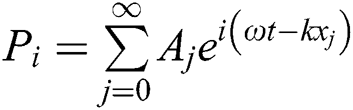 is standing pressure wave,
 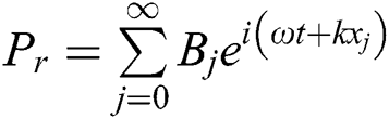 is reflected pressure wave,
  is transmitted pressure wave,
 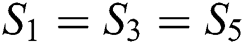 is the area of the pipe,
 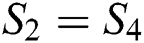 is the area of the silencer,
  is the mode number
  is the wave number,
  is the angular frequency
 is the sound speed in air.
The continuity conditions at each junctions can be obtained by applying continuity of pressure and volume velocity, the continuity conditions at the first junction (1–1) are:


And at the second junction (1–2) are:


And at the third junction (2–1) are:


And at the fourth junction (2–2) are:


where  denotes the axial acoustic velocity, given by the momentum equation:

where  is the fluid density,
  is the imaginary unit.
The algebraic system of the DCS model can be obtained from Eqs. (3) to (10), the Eigen functions orthogonally properties are used [19]. Where  and
and  ,
,  .
.
The following set of eight simultaneous complex equations:


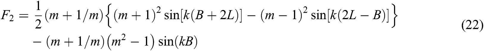
where 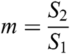 is the area ratio,
  are the transmission coefficient. By solve from Eqs. (12) to (19), to get the transmission coefficient:


The PTC is:

The attenuation TL is:

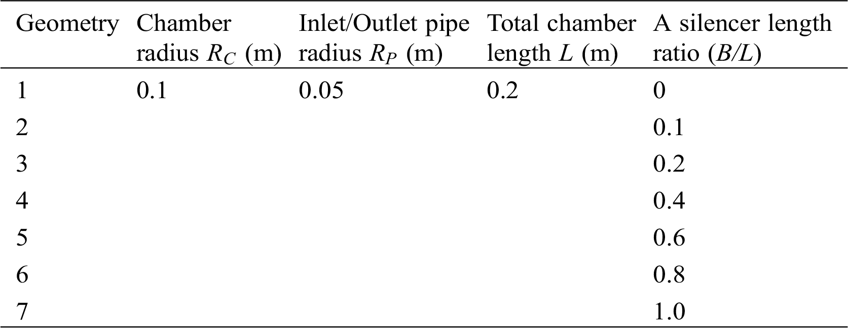
For the most of calculations were considered in the computational parts of the work the radius of the chamber and the inlet/outlet pipe are 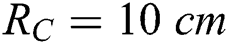 and
and 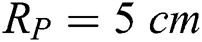 . A silencer is now added with a thickness
  is a ratio of the total chamber length
  . The chamber and pipe dimension and the rest of dimensions considered in each silencer length ratio (B/L) configuration are included in Tab. 1.
Table 1: Double-chamber silencer (DCS) geometry
Typical results shown a Figs. 3 and 4(For B/L= 0, 1.0, 0.2, 0.4, 0.6, 0.8, 1.0) shows the desirable properties acoustic TL of this type of silencer, namely its high attenuation over a wide frequency range. The properties acoustic TL at all Octave Band Center Frequencies are presented in Tab. 2.
Fig. 3 exhibits the behavior for the DCS, as expected, for the expansion chamber without silencer, the domes of acoustic TL is equal, for the expansion chamber with silencer the domes is replaced by unequal domes, the first dome of each silencer geometry configuration is smaller in amplitude and frequency band than the second one. When the frequency increases, the first dome of the acoustic TL increases to peak then the second dome pair tends to disappear, then go up again to peak, and so on. On other hand, the effect of silencer geometry configuration, when the silencer length ratio (B/L) increases, the second dome widens and tends to cover the two domes of the simple acoustic TL of expansion chamber. This behavior of acoustic TL continue along frequency range, the cut-off frequency being 3000 Hz.

Figure 3: Transmission loss of double-chamber silencer (DCS) with different Silencer length ratio (B/L)
Table 2: The peak transmission loss (TL) at silencer length ratio along frequency range
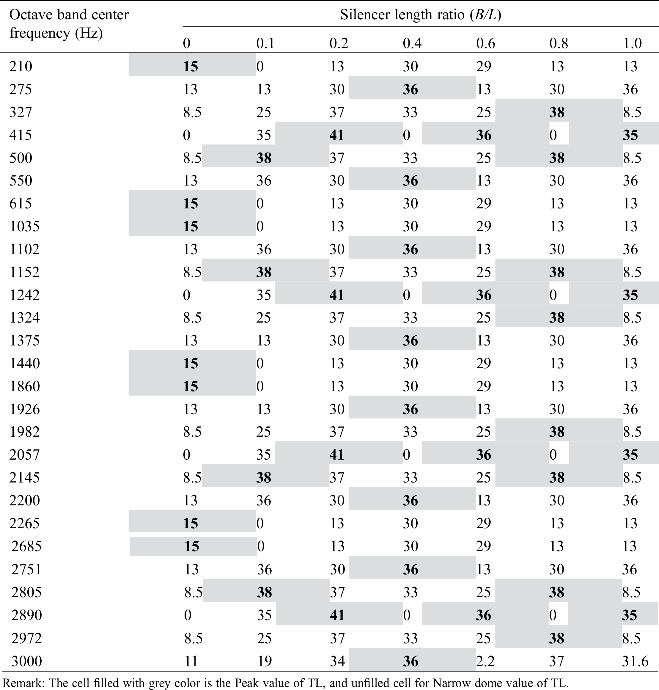
For all silencer geometry configuration the effect of silencer on acoustic TL was completely vanished sequently at frequencies 825 Hz, 1650 Hz, 2475 Hz respectively.
The acoustic TL with respect to silencer length ratio under full periodicity from 0 Hz to 800 Hz is shown in Fig. 4. As indicated in Fig. 4, the gain of acoustic TL will be changed when B/L is increased at the fixed frequency. Obviously, the gain effect in acoustic TL is dominated by B/L.
Moreover, acoustic TL becomes larger when B/L is increased. Visibly, B/L has high sensitivity to acoustic TL. Consequently, B/L is the key-parameter resulting in frequency shifting. Respectively, B/L is the powerful parameter in the gain of acoustic TL.
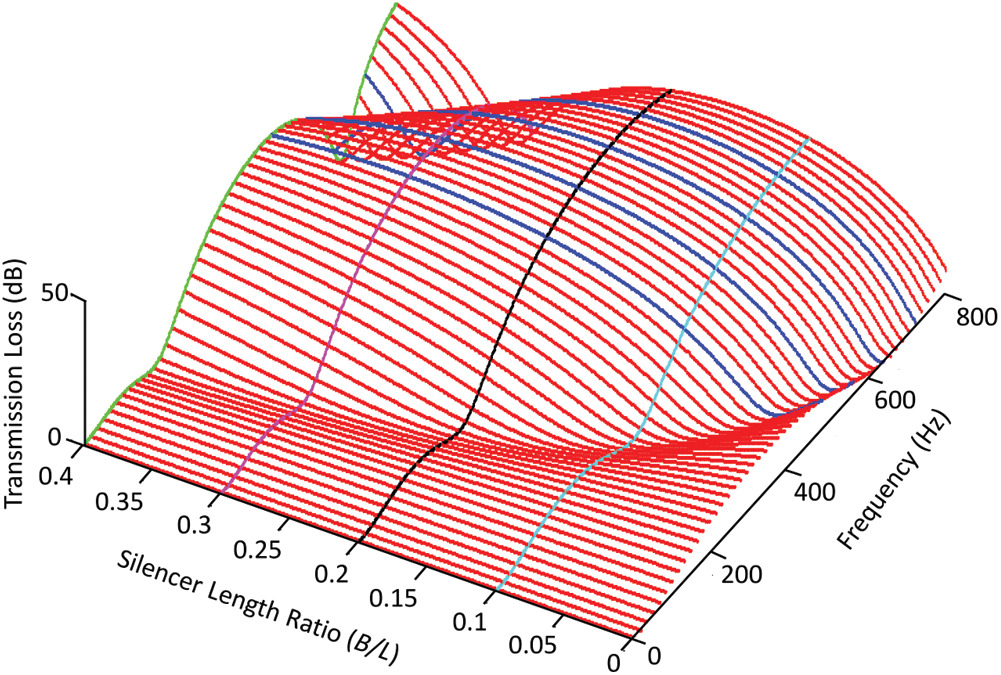
Figure 4: Transmission loss with different value of (B/L) along frequency range
In order to maximize the value of acoustic TL, the minimal value of length of B is planned and carried out. The three parameter B/L is chosen during the following analytical optimization processes. The method we are used to optimize the length of B of the acoustic silencer/filter shown in Fig. 2 is the Lagrange method. Eq. (25) is presented the governing equation to optimize the length of B.

From Eq. (20) for the silencer transmission coefficient, we can be written Eq. (26) as:

It should be noted that this derivation of the optimization equation under full periodicity from 0 Hz to 800 Hz could be solved by computer using Matlab® software and the results of derivation are shown in Figs. 5 and 6 to select the suitable length of B which gives the maximum transmission loss (TL).
It is possible to observe in Fig. 5 that the maximum acoustic TL is obtained in the resonance frequency of DCS (612 Hz) estimated by the analytical equation. Therefore, the values for this maximum attenuation (41.1 dB). We can conclude that the optimization process is a good tool to estimate the maximum TL within a defined range of DCS silencer shape. Thus, a manual process of adjusting the DCS shape may be impractical.
Tab. 3 shows the results obtained, where the two design variables (length and radius of the DCS silencer). In this work we optimize the length of silencer with fixed pipe radius, the main results are shown in this table. Just the results closest to the optimized value were exhibit in this table. The line filled with grey color is the optimized dimensions.
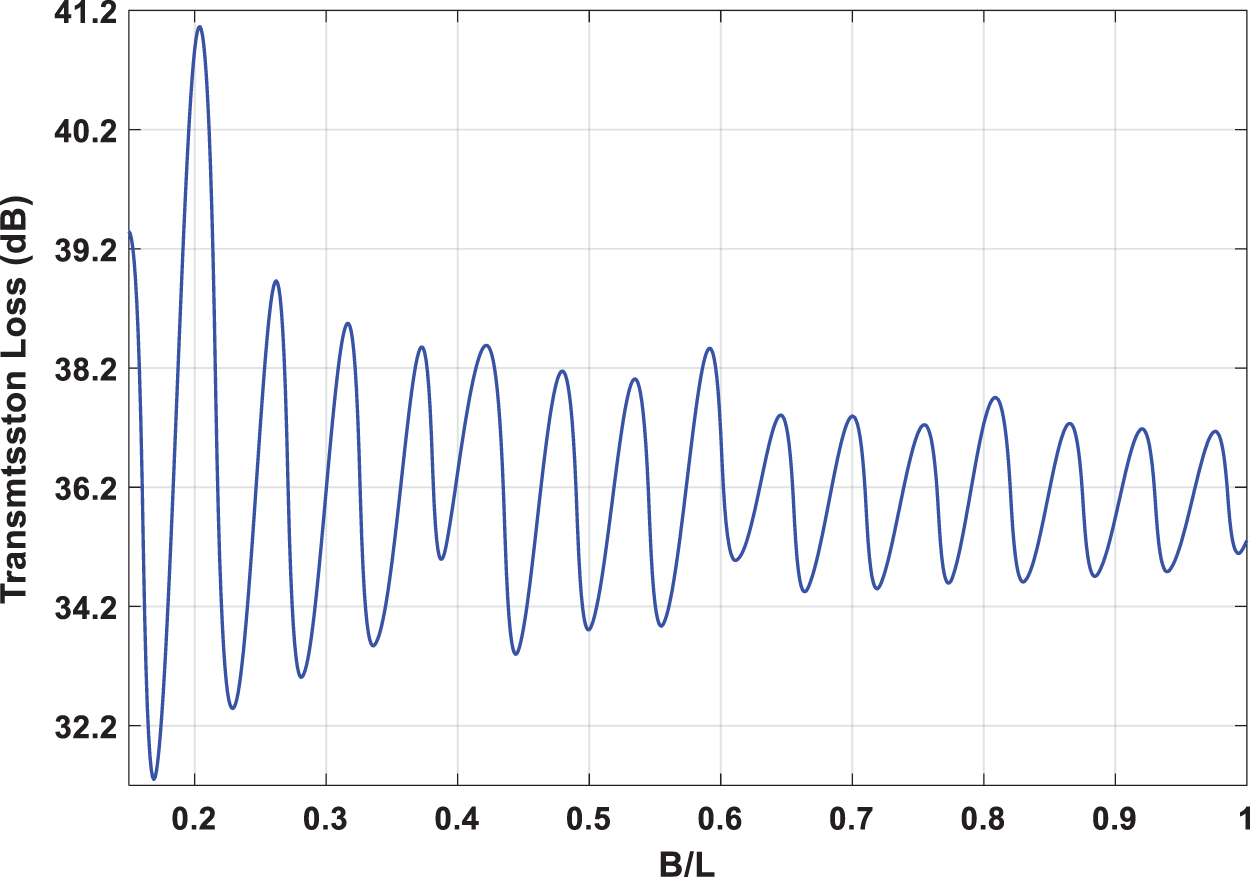
Figure 5: Relation between transmission loss and silencer length ratio (B/L)
Table 3: The Results obtained from optimization
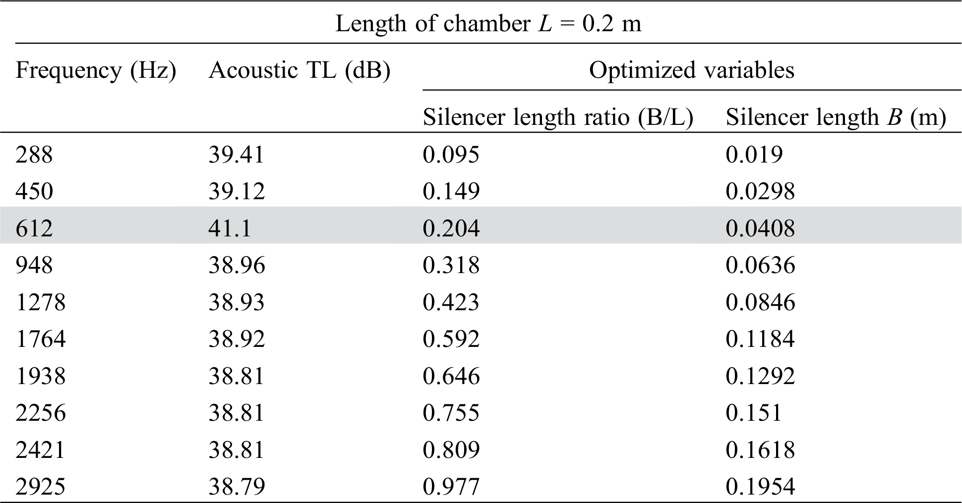
From this optimization process we conclude the best value of B/L is 0.204 in general range of frequency because it is has higher value of acoustic TL that is mean higher level sound attenuation. The desirable properties of acoustic TL of this type of silencer compared with the expansion chamber without silencer is shown in Fig. 6.
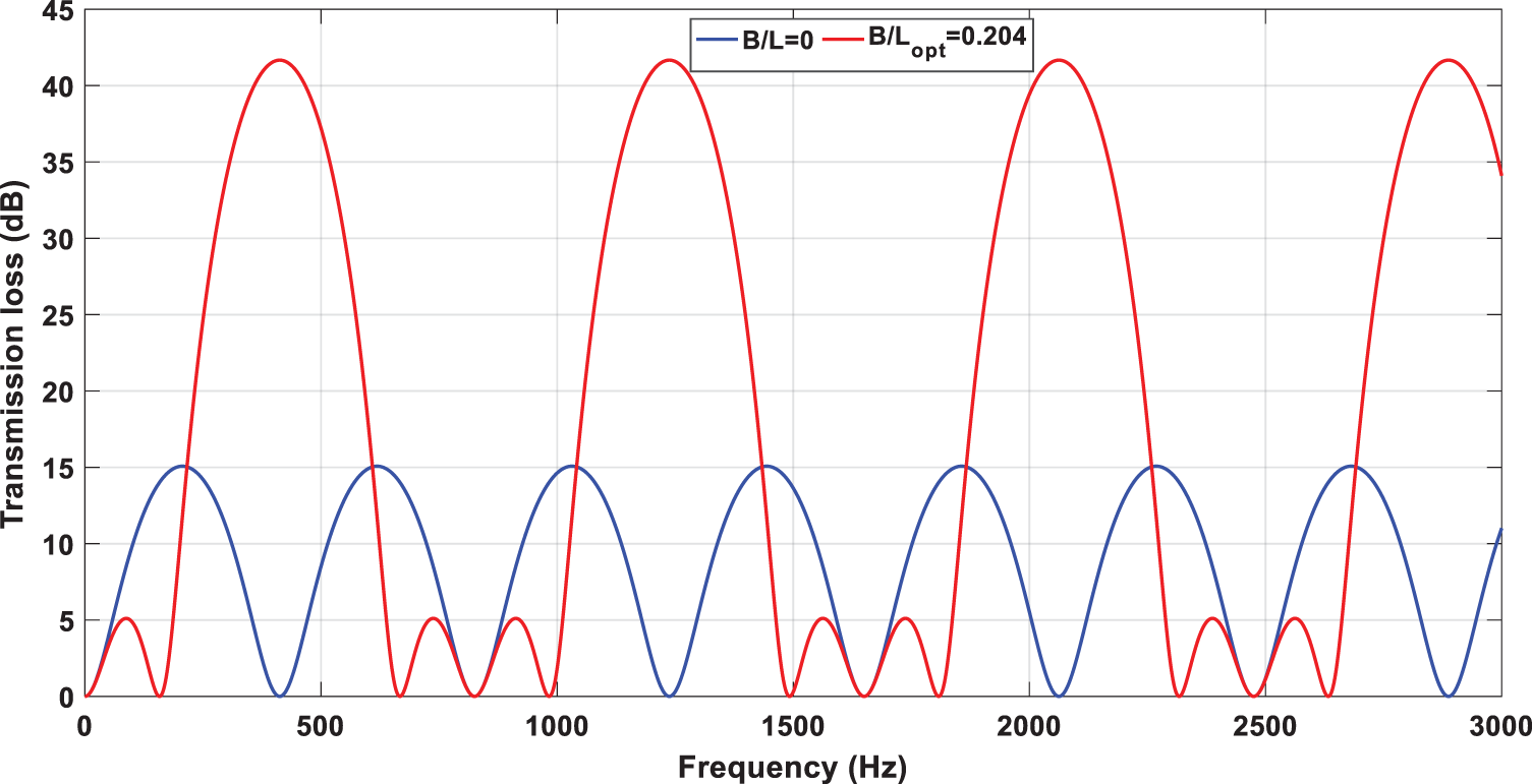
Figure 6: Transmission loss of double-chamber silencer (DCS) with minimal value of silencer length ratio (B/L), compared with the expansion chamber without silencer
In this work we presented complete mathematically study for optimal design of in Double-Chamber Silencer (DCS). The exact solution of Helmholtz equation was performed to calculate the power transmission coefficient (PTC) and the TL of silencer via Matlab® software for different silencer length. The Lagrange method were used for maximizing the acoustic TL using.
In this paper where defined the optimum silencer length is 0.0408 m with fixed pipe radius, encountered the maximum acoustic TL of 41.1 dB in the resonance frequency of DCS (612 Hz) estimated by the analytical equation. From the results we can conclude that the acoustic TL is maximized at the desired frequency. This work reinforces the rapid and efficient approach to an optimal design for DCS under narrow space.
Funding Statement: The author(s) received no specific funding for this study.
Conflicts of Interest: The authors declare that they have no conflicts of interest to report regarding the present study.
References
1. Tracor Inc. (1973). Guidelines on noise. American Petroleum Institute. Washington DC, pp. 55.
2. Prasad, M. G. (1984). A note on acoustic plane waves in a uniform pipe with mean flow. Journal of Sound and Vibration, 95(2), 284–290. DOI 10.1016/0022-460X(84)90550-9. [Google Scholar] [CrossRef]
3. Munjal, M. L. (1997). Plane wave analysis of side inlet/outlet chamber mufflers with mean flow. Journal of Applied Acoustics, 52(2), 165–175. DOI 10.1016/S0003-682X(96)00053-9. [Google Scholar] [CrossRef]
4. Munjal, M. L. (1987). Acoustics of ducts and mufflers with application to exhaust and ventilation system design. New York: John Wiley & Sons. [Google Scholar]
5. Craggs, A. (1976). A finite element method for damped acoustic systems: An application to evaluate the performance of reactive mufflers. Sound and Vibration, 48(3), 377–392. DOI 10.1016/0022-460X(76)90063-8. [Google Scholar] [CrossRef]
6. Sahasrabudha, A. D., Ramu, S. A., Munjal, M. L. (1991). Matrix condensation and transfer matrix techniques in the 3–D analysis of expansion chamber mufflers. Sound and Vibration, 147(3), 371–394. DOI 10.1016/0022-460X(91)90487-5. [Google Scholar] [CrossRef]
7. Seybert, A. F., Cheng, C. Y. R. (1987). Application of the boundary element method to acoustic cavity response and muffler analysis, vibration. Acoustics Stress, and Reliability in Design, 109(1), 15–21. DOI 10.1115/1.3269388. [Google Scholar] [CrossRef]
8. Cheng, C. Y. R., Seybert, A. F. (1991). A multidomain boundary element solution for silencer and muffler performance prediction. Sound and Vibration, 151(1), 119–129. DOI 10.1016/0022-460X(91)90655-4.
9. Ji, Z. L., Ma, Q., Zhang, Z. H. (1994). Application of the boundary element method to predicting acoustic performance of expansion chamber mufflers with mean flow. Sound and Vibration, 173(1), 57–71. DOI 10.1006/jsvi.1994.1217. [Google Scholar] [CrossRef]
10. Fonseca De Lima, K., Lenzi, A., Barbieri, R. (2011). The study of reactive silencers by shape and parametric optimization techniques. Journal of Applied Acoustics, 72(4), 142–150. DOI 10.1016/j.apacoust.2010.11.008. [Google Scholar] [CrossRef]
11. Lee, J. W., Jang, G. W. (2012). Topology design of reactive mufflers for enhancing their acoustic attenuation performance and flow characteristics simultaneously. International Journal for Numerical Methods in Engineering, 91, 552–570.
12. Lee, J. W. (2015). Optimal topology of reactive muffler achieving target transmission loss values: Design and experiment. Journal of Applied Acoustics, 88, 104–113.
13. Oh, K. S., Lee, J. W. (2015). Two-step design process for optimal suction muffler in reciprocating compressor. Journal of Mechanical Science and Technology, 29, 269–278.
14. Yu, X., Tong, Y., Pan, J., Cheng, L. (2015). Sub-chamber optimization for silencer design. Journal of Sound and Vibration, 351, 57–67.
15. Yedeg, E. L., Wadbro, E., Berggren, M. (2016). Interior layout topology optimization of a reactive muffler. Journal of Structural and Multidisciplinary Optimization, 53, 645–656.
16. Jang, G. W., Lee, J. W. (2017). Topology optimization of internal partitions in a flow-reversing chamber muffler for noise reduction. Journal of Structural and Multidisciplinary Optimization, 55, 2181–2196.
17. Lee, J. K., Oh, S. K., Lee, J. W. (2020). Methods for evaluating in-duct noise attenuation performance in a muffler design problem. Journal of Sound and Vibration, 464, 114982. DOI 10.1016/j.jsv.2019.114982. [Google Scholar] [CrossRef]
18. Selameta, A., Deniab, F. D., Besa, A. J. (2003). Acoustic behavior of circular dual-chamber mufflers. Journal of Sound and Vibration, 265, 967–985. [Google Scholar]
19. Selamet, A., Ji, Z. L. (1999). Acoustic attenuation performance of circular expansion chambers with extended inlet/outlet. Journal of Sound and Vibration, 223, 197–212. [Google Scholar]