DOI: 10.32604/sv.2021.04410
ARTICLE
Dynamic Modeling of the Feed Drive System of a CNC Metal Cutting Machine
1Department of Applied Mechanics, Bauman Moscow State Technical University, Moscow, Russia
2Department of Bases of Machine Designing, Bauman Moscow State Technical University, Moscow, Russia
3Skolkovo Institute of Science and Technology, Moscow, Russia
*Corresponding Author: H. Heydarnia. Email: hodaheydarniya93@gmail.com
Received: 29 September 2018; Accepted: 17 December 2020
Abstract: Studying the vibrational behavior of feed drive systems is important for enhancing the structural performance of computer numerical control (CNC) machines. The preload on the screw and nut position have a great influence on the vibration characteristics of the feed drive as two very important operational conditions. Rotational acceleration of the screw also affects the performance of the CNC feed drive when machining small parts. This paper investigates the influence of preload and nut position on the vibration characteristics of the feed drive system of a CNC metal cutting machine in order to be able to eliminate an observed resonance occurred at high rotational speeds of the screw, corresponding to high feed rates. Additionally, rational structural parameters of the feed drive system are selected in order to increase the rotational acceleration for improving the performance of the CNC machine. Experiments and analyses showed that by selecting specific parameters of feed drive system and simultaneously applying a certain value of preload, a 97% increase in rotational acceleration and 30% time reduction considering the vibration resistance at high rotational speeds can be achieved.
Keywords: Machining performance; CNC machine tools; vibration characteristics; machine tool; dynamic modeling
Machine tool feed drives have been widely designed and manufactured for various applications. Performance of the CNC feed drives is evaluated based on the surface quality of the machined parts as well as time required for cyclic operations [1]. Frequency response function (FRF) and stability lobe diagrams (SLDs) are both effective tools for assessing the performance of CNC drives. FRF experimentally determines the machining efficiency and quality [2].
In comparison to direct drives, ball screw feed drives are cheaper and less sensitive to inertia variation and disturbance forces; therefore, they are widely used in engineering applications. However, the resonance modes of ball screw feed drive can be excited when machining with high accelerations, which can adversely affect the positioning accuracy and consequently, finished surface quality [3]. As a solution, preload is applied on the screw for pushing the resonance frequencies out of frequency range of interest. It was shown in a study [4], that preload on machine tool joints has significant effects on dynamic stiffness of the spindle nose. Influence of preload on linear guides on vibrational behavior of the feed drive system is also investigated by Lin et al. [5]. It is shown in this study, that preload of the linear guides greatly affects the vibrational behavior, associated with spindle head. It is also stated that the dynamic stiffness of the spindle head can be enhanced by increasing the preload on the linear guides. However, these results are obtained for specific systems under a fixed operational condition and the effect of nut position on dynamics of the feed drive is not considered. Nut produces a significant lateral restraint on transverse vibration of the screw. The effect of transverse vibration of the screw vary with time as the nut moves along the screw [3]. This implies that the natural frequencies of the ball-screw system change with time during the machining process [6]; therefore, it is necessary to consider the effect of nut position on the vibrational behavior of the machine tool.
The aim of this study is to investigate the influence of nut position and preload on screw on dynamic behavior of a CNC metal cutting machine (Miller) and to improve the performance of the feed drive system considering the resonance resistance [7]. The studied horizontal feed drive system mainly consists of linear guides, ball screw/nut and ball bearings. A finite element model of the feed drive system is built to capture the natural frequencies and mode shapes of the feed drive. The effect of nut movement throughout the screw shaft of the feed drive on its natural frequencies and mode shapes during the machining process is also studied. It is found that at the extreme left position (or right position, due to symmetrical shape of feed drive) of the nut, the natural frequencies of the feed drive system become close to rotational frequency when machining at maximum rotational speed of the screw, corresponding to maximum feed rate. This effect is undesirable, as it can lead to excitation of dangerous vibrations of screw, which results in jamming at high feed rates. The easiest way to avoid this undesirable effect is limiting the feed rate, which negatively affects the productivity and performance of the machine tool. A more complicated method to avoid the mentioned problem is to increase the natural frequencies of the screw (shaft) by applying the preload on it. In this paper, the influence of different values of screw’s preload on its natural frequencies is studied. For this, a pre-stressed modal analysis is conducted based on finite element modeling and the results are compared with experiments. Calculations of maximum level of mechanical stresses in the grooves of the screw shaft is performed in a three-dimensional setting, and the strength estimation is carried out in order to select the appropriate value of preload. Additionally, calculations of static load capacity of feed drive bearings and selection of suitable bearing’s model (which can carry the preload) are performed.
Another way to increase the performance of the machine tool is to increase the rotational acceleration of the screw shaft during the machining of small parts. It is proposed in this paper to reduce the shaft diameter while using the original motor’s and gear’s model in order to achieve greater rotational acceleration by reducing the total inertia of the drive system. For this, a calculation is performed to determine the rotational acceleration for different shaft diameters. A suitable diameter is then chosen with considering the natural frequencies, and the preload value is corrected in order to prevent resonance at maximum feed rate at extreme nut positions.
The modal analysis performed on the CNC machine tool feed drive is discussed in this section. The vibration characteristics of the feed drive system are obtained by measuring the direct frequency response of acceleration of the system at point A on the screw and points B and C on the linear guides. The devices used for the vibration test mainly consisted of three accelerometers, impulse hammer, data acquisition NI9234, USB carrier 9162, computer with a system design platform LabVIEW and Fourier transform analyzer. The experimental setup is shown in Fig. 1.

Figure 1: Experimental setup for modal analysis
The accelerometers are mounted at points A, B and C for measuring the acceleration of vibrations. Sensitivity of the accelerometers are 3.56; 9.8 and 9.8 mV/g, respectively. The impulse hammer is used for transverse excitation of screw shaft of the feed drive. The acceleration and impact force signals are recorded by the data acquisition NI9234. FRFs are obtained using LabVIEW design platform system and Fourier transform analyzer. The first two natural frequencies are extracted for the case, when the nut is located at the middle of the shaft. The experiments are repeated for different positions of the nut. At the extreme right and left positions of the nut, the minimum distance between the nut and the end bearings is 185 mm. The location of the origin point is selected to be at 185 mm from the end of left bearing. The vibration spectra of the feed drive for 3 positions of nut including left position (distance from nut to origin is 0 mm), middle position (distance from nut to origin is 425 mm) and right position (distance from nut to origin is 850 mm) are shown in Fig. 2.

Figure 2: Vibration spectra of the feed drive system for three different positions of the nut. а) Left position of nut and b) Middle position of nut
The experimental results show, that the maximum natural frequencies correspond to the middle position of nut, and, when nut moves from center of screw towards the ends of the screw, the natural frequencies decrease. Fig. 3 illustrates the relationship between the values of natural frequencies and location of nut.

Figure 3: Relationship between the natural frequencies of the feed drive system and the nut position
3 Calculation of Design Parameters and Preload of Feed Drive for Enhancing the Performance
3.1 Natural Frequency and Mode Shape Extraction for the Feed Drive System
A modal analysis in ANSYS workbench software is performed to obtain the natural frequencies and mode shapes of the feed drive system for different nut positions. For this, the model is divided by tetrahedral finite elements (10 nodal elements). Boundary conditions are set using the bushing function to provide translational and rotational movements with the corresponding stiffness values at joints between shaft and bearings/nut. The stiffness values at the joints are selected and updated based on comparison with experimental results for different positions of nut. Fig. 4 shows the first four mode shapes and their corresponding natural frequencies of feed drive system, which are correlated to vibration of the shaft (nut at the extreme left position).

Figure 4: Fundamental vibration mode shapes and corresponding natural frequencies of the horizontal feed drive system. а) First mode shape (34.733 Hz), b) Second mode shape (34.85 Hz), c) Third mode shape (112.4 Hz) and d) Fourth mode shape (112.77 Hz)
By comparing the finite element model and experimental results, we can conclude that the finite element model is built with an acceptable accuracy. Fig. 5 illustrates both FEM and experimental results for comparison. Based on both FEM and experimental results, at the extreme positions of the nut, the natural frequencies of the screw (for the first and second mode shapes) become close to rotational frequency (30 Hz) at maximum rotational speed (1800 rev/min) of the screw, corresponding maximum feed rate, which leads to resonance.

Figure 5: Comparison between FEM and experimental results
3.2 Influence of Preload on Shaft on the Natural Frequencies
The effect of preload on screw shaft on the natural frequencies is discussed in this section. By applying a suitable value of preload and consequently increasing the natural frequencies, resonance can be prevented. Pre-stressed modal analysis for the feed drive is performed in ANSYS workbench software for different values of preload, and first four mode shapes and corresponding natural frequencies are obtained. As the feed drive has natural frequencies close to forced frequency (corresponding to maximum rotational speed) at extreme left position of the nut, the pre-stressed modal analysis is conducted for this position of nut for different values of preload. Based on the results, the natural frequencies rise when preload increases (see Fig. 6).

Figure 6: Relationship between natural frequencies of the feed drive and preload
3.3 Selection of Preload on Shaft of the Feed Drive for Eliminating Resonance at Maximum Feed Rate
Although higher values of preload result in significant increase of lower natural frequencies, preload can be increased only up to a certain limit. It is due to the strength conditions of the shaft, particularly on grooves of the shaft, where stress concentration occurs. Permissible tensile stress on the shaft considering avoidance of local plastic deformations of the material is selected based on the following inequality [8]:

where  represents the permissible tensile stress on the shaft, and
  represents the yield strength of material. The value of yield strength is selected from the manufacture’s catalog (785 MPa) for the shaft material (steel 40cr, Russian standard steel). Consequently,
  .
.
To select the appropriate preload on shaft, a static analysis in ANSYS workbench software is performed for one preloaded section of the shaft to determine the stress fields. According to the analysis results, the maximum preload that can be applied to the shaft is 20000N, which results in stresses (257.9 MPa) less than permissible stress (see Fig. 7). The analysis is repeated for the preloaded shaft section with larger grids for verifying the convergence of the solution.

Figure 7: Stress field of shaft section under the preload of 20000N
3.4 Modeling of Thrust Bearings for Providing the Specified Preload
The preload on shaft, calculated in the previous section, is transmitted to the drive’s frame via radial-thrust bearings. Therefore, permissible preload depends not only on strength conditions of the shaft, but also on static load capacity of the bearings’ model. In this section, a calculation of static load capacity of bearings used in feed drive is performed to determine the maximum tolerable preload (bearing model- 46100, Russian standard). Then, the capability of other bearing models is analyzed. It should be ensured that preload does not exceed the static load capacity of the bearing [8]:

where the equivalent static load  is determined from the next Eq. (8):

 represents a coefficient, selected from the catalog of corresponding bearing’s manufacturer and
  represents the force on screw.
 can be determined by following Eq. (8):

where  represents the axial load on screw and Fap represents the driving torsional force.
It is found that preload on the studied bearing (model-46100) must not exceed 1500N. In this case, natural frequencies can be increased from 34.733 Hz only to 35.6 Hz. For overcoming this limitation it is proposed to select a suitable bearing model that can support higher preload values. In order to select the most suitable bearings’ model, calculations of static load capacity are conducted for a number of bearing models. Bearings 46100, 46101, 46102, 46200 and 46201 fit well with the dimensions of the machine tool. However, the calculations are also conducted for a series of other bearings (46301 and 46303) which support even more preload. In designing stage of the machine tool, the designer can utilize these bearing models by using additional bushings. Tab. 1 shows the maximum preload supported by different bearings.
Table 1: Maximum tolerable preload for different bearings, obtained by static load capacity calculation
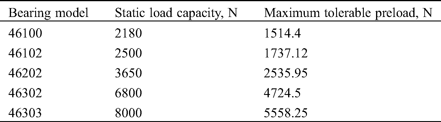
Based on the results, it is obvious that by replacing the initial bearing 46100 with bearing 46303, a preload of 5558N can be applied, and therefore the natural frequency can be increased from 34.733 Hz to 45.268 Hz (when nut is located at it is extreme left position), which is far from resonance frequency. Thus, in the further calculations, we limit ourselves to a maximum preload of 5558N.
3.5 Determining the Maximum Allowable Reduction of the Preloaded Shaft’s Diameter Considering the Vibration Resistance
As mentioned before, high acceleration is a key parameter, assessing the performance of machine tool. It becomes more important when machining small parts by a lightweight type of machine tool. In this work, it is proposed to reduce the diameter of the shaft in order to reduce the moment of inertia and consequently increase the acceleration of rotation of the shaft. However, it is also important to check that the vibration resistance is preserved simultaneously and natural frequencies are higher and far from the critical frequency (30 Hz), corresponding to maximum feed rate. In other words, as diameter of the shaft decreases, it must be assured that the natural frequencies are still far from the rotation frequencies, since the natural frequencies decrease by reducing the shaft diameter. For keeping the natural frequencies far from the resonance frequency as diameter is decreased, a preload equal to the permissible value in the previous section (5558N) is applied to the shaft simultaneously. The studied bearing model is 46303. Static and modal analyses are conducted to determine the natural frequencies of the shaft with different diameters (considering the left position of nut). Size of diameters are chosen from the catalog of corresponding manufacturer of ball screws (shafts with diameters 14 mm and 10 mm) [9]. Based on static analyses, the maximum preload for shafts 14 mm and 12 mm are 17000N and 10000N, respectively. The results of modal analyses are presented in Tab. 2. Natural frequencies of the shaft without applying a preload are presented in Tab. 3 for comparison.
Table 2: Relationship between the natural frequencies and nominal diameters of preloaded shaft (5558N)
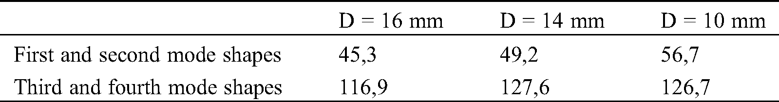
Table 3: Relationship between the natural frequencies and nominal diameters of the shaft without preload
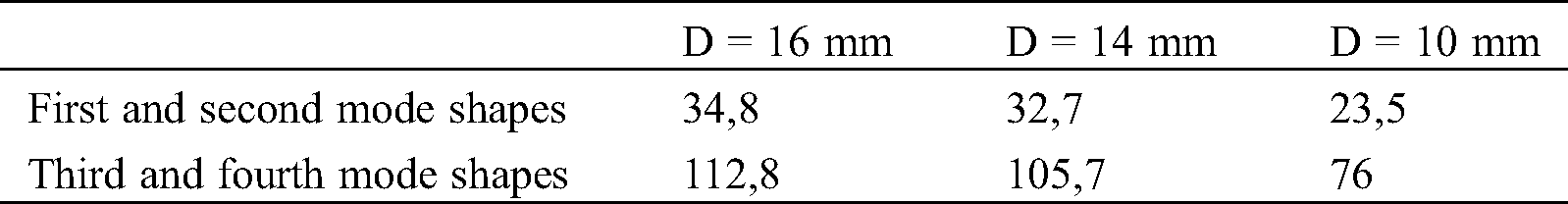
It can be seen from the results, that by applying the preload of 5558N the natural frequencies will be far from the critical eigenvalues (30 Hz) at the maximum speed of shaft rotation (1800 rev/min).
3.6 Estimation of the Efficiency Improvement of the Preloaded Feed Drive during Milling Process
This section demonstrates an example of time reduction for machining holes with diameters less than 10 mm for showing how efficiency improves as a result of applying the proposed changes in the feed drive. Machining the holes is required to be done with maximum acceleration at maximum feed rates. The maximum rotational speed of the shaft (diameter of 16 mm) is  . In this section, a calculation is conducted to determine the rotational acceleration and feed rate of the shaft with proposed diameter when machining circles with different diameters. The diameters are selected from the catalog of corresponding manufacturer. Here, three different diameters are selected:
  , and
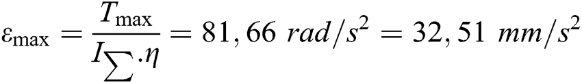
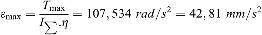
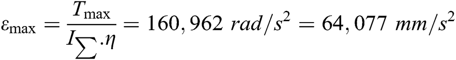
, and  . Maximum rotational acceleration of the shaft
  [
[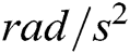 ] is calculated by following equation:

where  represents the maximum moment of inertia of the motor [
 ] (for the studied motor-PL57H110 it is equal to
  [10]),
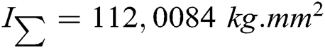
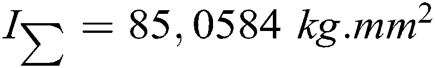
  represents the total moment of inertia [
 ] and the
  is a coefficient equal to 0,3.
Total moment of inertia in this case is calculated based on the next equation:

where  represent the moment inertia of rotor, moment inertia of coupling, moment inertia of the shaft and moment inertia of the vertical module of the machine tool, respectively. M represents the mass of vertical module of the machine tool (
 20 kg) and
  represents the pitch of the screw.
Based on the catalog of corresponding manufacturer [10], rotary inertia is equal to  . Moment of inertia of the coupling is calculated based on the following equation:

where  is external diameter of the coupling,
  represents the coupling’s length and
  represents the coupling’s density. Substituting the values in the Eq. (7) we will get
  .
.
First proposed shaft has the next characteristics:  - nominal diameter of the screw shaft,
  - lead of screw,
  - shaft length,
  - shaft density. Therefore:
 ,
,  .
.
The following characteristics are related to the second shaft:  ,
,  ,
,  ,
,  ,
,  ,
,  .
.
Finally, characteristics of the third shaft are:  ,
,  ,
,  ,
,  ,
,  ,
,  .
.
Based on the above calculation results, it can be seen that the rotational acceleration of shaft increases by 97%, if the diameter of the shaft is reduced by 6 mm. Next, feed rates of machining a small circle with a diameter of 10 mm are determined for different obtained accelerations  (see Fig. 8). Feed rate and time required for machining one circle t are determined by the following formulas:

where d represents diameter of the circle, throughout which passes the tool tip, and  represents the length of this circle.

Figure 8: Geometrical relationships in milling process of the circle
Time and feed rates for different rotational accelerations are presented below:
at 
at 
at 
Based on the above calculation results, it is seen that the time required for machining a circle with a diameter of 10 mm is reduced by 28.7% as a result of shaft diameter reduction. Further, the same calculation is conducted for different machined circles (with different diameters) (see Tab. 4). According to the results in Tab. 4, the smaller diameter of machined circle, the more acceleration will affect the processing time. Therefore, acceleration plays an important role mostly when machining small parts. Tab. 4 shows the dependence of feed rate on diameter of machined circle.
Table 4: Influence of rotational acceleration of shaft  [mm/s2] and diameter of machined part d’[mm] on machining time
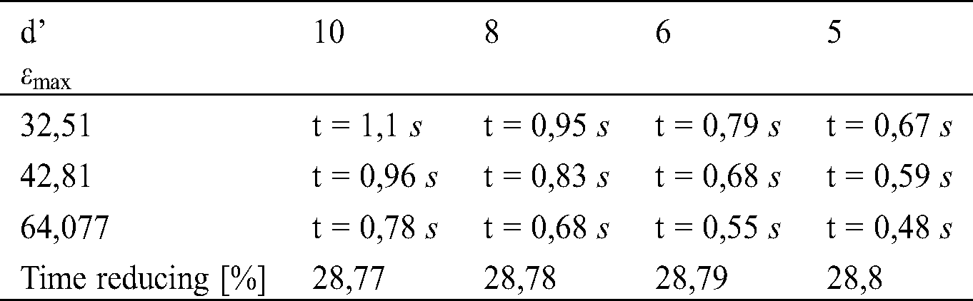
Starting from a certain value of diameter of the machined circle, only feed rate affects the time of machining process, and the rotational acceleration of the shaft stops affecting the machining time (see Fig. 9). This diameter can be determined as  .
.

Figure 9: Effectiveness of rotational acceleration and the feed rate on processing time in dependence on the machined circle diameter
Influence of preload and nut position on the vibration characteristics of the feed drive system of a CNC machine tool is investigated in this study. Design parameters of feed drive system are also selected in order to be able to increase the rotational acceleration and consequently, improve the performance of the CNC machine tool. Based on results and analyses, the following conclusions are made:
1. Based on the modal analysis and experimental results, at the extreme left position of the nut, the natural frequencies (34,73 Hz) are close to resonance frequencies at the maximum rotational speed of the screw (30 Hz)
2. To increase the natural frequencies of the feed drive for avoiding resonance, it is proposed to apply the preload on the shaft. To provide the preload on shaft, a suitable model of the bearings is selected, which tolerates maximum preload of 5558N. In this case, the natural frequencies increase up to 30%.
3. To increase the machining speed and reduce the time required for machining small parts, it is proposed to reduce the diameter of the shaft from 16 mm to 10 mm. It is shown that by reducing the diameter, the rotational acceleration of the shaft can be increased up to 97%.
4. To find out the influence of the shaft’s rotational speed on the machining time, calculations are performed to determine the feed rate and machining time of small holes with different diameters. It is concluded that the smaller diameter of machined circle, the more acceleration will affect the processing time. Starting from a certain diameter of the machined circle, only feed rate affects the time of machining process, and the rotational acceleration of the shaft stops affecting the processing time.
Acknowledgement: The author would like to express deepest thanks to Automation Manufacturing Laboratory at Bauman Moscow State Technical University for all the help and experience. Also, the author would like to express extreme gratefulness to “Modular Mechanics” Company, Machine Production Department at Bauman University, for sharing their machine tool and experimental laboratory as well as their kind technological and informational consultations and technical support.
Funding Statement: The author(s) received no specific funding for this study.
Conflicts of Interest: The authors declare that they have no conflicts of interest to report regarding the present study.
1. Hecker, R. L., Flores, G. M., Xie, Q., Haran, R. A. (2008). A review of machine-tools servocontrol level. Latin American Applied Research (International Journal), 38(1), 85–94. [Google Scholar]
2. Dhupia, J., Powalka, B., Katz, R., Ulsoy, A. G. (2007). Dynamics of the arch-type reconfigurable machine tool. International Journal of Machine Tools and Manufacture, 47(2), 326–334. DOI 10.1016/j.ijmachtools.2006.03.017. [Google Scholar] [CrossRef]
3. Vicente, D. A., Hecker, R. L., Villegas, F. J., Flores, G. M. (2012). Modeling and vibration mode analysis of a ball screw drive. International Journal of Advanced Manufacturing Technology, 58(1–4), 257–265. DOI 10.1007/s00170-011-3375-6. [Google Scholar] [CrossRef]
4. Mi, L., Yin, G., Sun, M., Wang, X. (2012). Effects of preloads on joints on dynamic stiffness of a whole machine tool structure. Journal of Mechanical Science and Technology, 26(2), 495–508. DOI 10.1007/s12206-011-1033-4. [Google Scholar] [CrossRef]
5. Lin, C. Y., Hung, J. P., Lo, T. L. (2010). Effect of preload of linear guides on dynamic characteristics of a vertical column-spindle system. International Journal of Machine Tools and Manufacture, 50(8), 741–746. DOI 10.1016/j.ijmachtools.2010.04.002. [Google Scholar] [CrossRef]
6. Holroyd, G., Pislaru, C., Ford, D. G. (2003). Modelling the dynamic behavior of a ball-screw system taking into account the changing position of the ball-screw nut. Transactions on Engineering Sciences, 44, 12. DOI 10.2495/LAMDAMAP030291. [Google Scholar] [CrossRef]
7. Modular Mechanics Company (2017). Machine Tool “Miller”. http://m-drives.ru/products/miller. [Google Scholar]
8. Reshetov, D. N. (1989). Machine parts. Russia: Machining Engineering. [Google Scholar]
9. Hiwin Manufacturing Company (2017). Hiwin Ball Screws. https://www.hiwin.com/pdf/ballscrews.pdf. [Google Scholar]
10. Pure Logic Development and Research Company (2017Rotor PL86H75-D14. https://purelogic.ru/catalog/elektroprivod/shagovye_dvigateli_i_aksessuary/shagovye_dvigateli/. [Google Scholar]
 | This work is licensed under a Creative Commons Attribution 4.0 International License, which permits unrestricted use, distribution, and reproduction in any medium, provided the original work is properly cited. |