| Sound & Vibration |
DOI: 10.32604/sv.2021.015293
ARTICLE
Experimental Modal Damping Identification of a Mechanical Structure Using Video Magnification Technique
1Mechanical Engineering Department, Faculty of Engineering, Lebanese University, Beirut, Lebanon
2Civil Engineering Department, Faculty of Engineering, Lebanese University, Beirut, Lebanon
3Universite Grenoble Alpes, CNRS, Grenoble INP, 3SR, Grenoble, France
4SDM Research Group, Mechanical Engineering department, International University of Beirut, Beirut, Lebanon
5Mechanical Engineering department, Lebanese International University, Bekaa, Lebanon
*Corresponding Author: Jaafar Hallal, Email: jaafar.hallal@ul.edu.lb
Received: 07 December 2020; Accepted: 09 March 2021
Abstract: Vibration can be introduced in all mechanical fields in our life. Engineers try to avoid its negative effect leading in some cases to deformation in the machines. Many researches are dedicated to study the identification of damping especially in multi degree of freedom systems with particular attention to the source of energy dissipation. They focus on developing new tools or methods which may be used in real problems to obtain accurate results about the amount (or value) and the location of energy dissipation in the structure. The aim of this paper is to present an original procedure aims to experimentally determine the modal damping ratio of a mechanical structure. The proposed procedure consists of extracting the Frequency Response Function of the vibrating system using the video magnification method and then calculate the modal damping ratio using the 3-dB method. These experimental measurements are carried out by giving an external force on a cantilever beam, then the modal damping ratios are extracted using motion magnification. The obtained results show a relative error less than 4.2% between the experimental measurements and the analytical calculation for the Frequency Response Function (FRF) curves. The novelty of the paper is to combine the video magnification technique and the 3dB method in a procedure that aims to experimentally measure the modal damping of a mechanical structure. The proposed procedure in this paper represents the damping identification as a simple and easy engineering application.
Keywords: Vibrations; modal damping; experimental measurement; video magnification
Nowadays, damping problems have significant concerns in many industrial systems. Damping could be a significant factor in many different fields: the design of buildings in active seismic areas, bridges in windy regions, etc. Damping has many types such as viscous, hysteretic and coulomb friction. The mathematical approximation of viscous damping has been used in awareness limitation to approach as much as possible from the real event. However, the challenge is to represent and identify all the sources of damping which is very different in terms of nature, extent and distribution within the structure. The separation and the evaluation of all the sources of damping are practically impossible in a structure, still it can be estimated by many ways and methods, that have their own advantages and limitations.
Rayleigh [1] assumes in his commonly used model that instantaneous generalized velocities are the only variables. Taylor et al. [2] then expands the model which encapsulates the damping behavior in a dissipation matrix, linked to the stiffness and mass. Actually, any model with non-negative rate energy dissipation can be a representative model. The damping mechanisms can be divided into three classes:
• Material damping, or the energy dissipated throughout the material of the structure.
• Boundary damping, or the energy dissipated by the interface between the parts of the structure
• Viscous damping, or the dissipation of energy associated with the contact between the structure and a fluid.
Despite that the variety of the micro structural mechanisms affects the material damping according to Bert [3], an equivalent linear viscoelastic continuum model of the material is more adequate to represent the small strains. Then, the material damping can be taken into account via the principle of viscoelasticity. The damping of a hall structure is always higher than the intrinsic material damping of its components because of the frictional micro-slipping at joints and the air pumping in riveted beams. The energy loss mechanism is non-linear, although it can be considered linear by assuming small damping according to Heckl [4]. The change in boundary conditions affects the modal damping ratios, according to a study by Oliveto et al. [5]. They also found that Rayleigh damping model is independent of the boundary conditions and they can convert the modal damping ratios from one boundary condition to another. Maia et al. [6] has demonstrated a fractional damping concept of the linear systems which explain the behavior displayed by common viscous and hysteric damping models. The model provided by Agrawal et al. [7] combines the damping forces and the fractional derivative of displacement and the fractional differential equations of motion. While Adhikari et al. [8] developed four indices in order to quantify non-viscous damping in discrete linear system, these indices are based on non-viscous damping, the residue matrices of the transfer function and the measured complex modes of the system.
The identification of damping ratio is very important in many fields, like structural dynamic and condition monitoring. Lancaster [9] proposed a method for mass, stiffness and damping matrices identification for a given system with normalized input data for only viscous damping. Beliveau [10] used mode shapes, natural frequencies, damping ratios and phase angles to identify the parameters of the viscous damping matrix. While, Minas et al. [11] presented a finite element model to assume the analytical mass and stiffness matrices, which are reduced to the size of the modal data available from experiments. For complex Frequency Response Function (FRF), Chen et al. [12] proposed an realistic experimental method for getting the spatial model and solving the damping matrix based on data from testing without error calibration. Pilkey [13] proposed two methods for computing the viscous damping matrix developed from the Lancaster [9] concept, using complex modal data. The two methods require the knowledge of the mass matrix, eigenvalues and eigenvectors. Friswell et al. [14] proposed a direct method of viscous damping identification using complex modal data.
Okuma et al. [15] proposed a method of identifying experimental set of spatial matrices valid only for the hysterical damping for the entire frequency range of interest using FRFs. Using FRFs, it is possible to set the number of degrees of freedom much larger than the number of resonant frequencies located inside the frequency range of interest. The advantage of this method is in its ability to represent the arbitrary dynamic characteristics of the structure by its spatial matrices. Lee et al. [16] presented an algorithm for the identification of the damping matrices using frequency response matrix depending almost entirely on the accuracy of the measured FRFs, especially their phase angles. Adhikari [17] identified the damping of the system as viscous damping. Most of the above damping identification methods are based on viscous damping model and require the complex modal data which is obtained using modal analysis of complex FRF. Adhikari et al. [18] identified non-viscous damping model using an exponentially decaying relaxation function.
Some research efforts have also been made to update the damping matrices. Phani et al. [19] proposed that the complex modes arising out of non-proportional dissipative matrix is very important to successful modeling and identification of correct physical damping mechanisms. Arora et al. [20] identified the structural damping matrix using complex FRFs of the structure. Then, Arora et al. [21] proposed a viscous damping identification method in which viscous damping is identified explicitly. Pradhan et al. [22] proposed FRF-based model updating method in which normal FRFs (NFRFs) is used for updating damping matrices along with mass and stiffness matrices. Arora [23] proposed a structural damping identification method using normal frequency response functions (NFRFs), which are obtained experimentally.
Recently, numerical FEM modelling are used for motion detection. Such numerical models need to be validated experimentally to predict the behavior of the structure. Contact sensors (accelerometers) are used for modal analysis with high accuracy [24–26]. However, these devices are not effective for small structures due to their masses. Other devices are also being used as a substitute device for movement measurements (GPS, hologram interferometry, speckle photography, laser Doppler vibrometer) [27–30]. Thanks to the advanced technology in the image sensors and high-performance optical lenses, the vision-based measurement technique is also used for displacement measurement of different engineering structures [31,32]. A modern approach called the video magnification technique which is applied using high frame per seconds (fps) recorded video can magnify the small motion of the structure [33–36]. The analysis of this processed video will provide the modal characteristics of the structure. These techniques use the signal processing approach to analyze image motions, as the Eulerian framework for fluid flow analysis. They are capable of detecting small subpixel motions that are presented in the videos of vibrating structures and thus, they are ideal for computing and visualizing the mode shapes. They are also able to separate the different modal motions through the use of temporal filtering [36]. The Camera-based measurements of displacement are compared against laser vibrometer and accelerometer measurements for verification [37]. As shown by Hallal et al. [38], this procedure represents an accurate low-cost vibration measurement device. The motion magnification technics are normally used as non-contact vibration measurements for the estimation of vibration modes and frequencies. Therefore, it is highly important to extend this method for modal estimation of the structures.
In this paper, a new procedure of modal damping identification is proposed for a multiple degree of freedom systems based on video magnification technique. The main focus of this work is the adaptation of the video magnification method for experimental damping identification, then use it in a real problem to obtain valuable information about amplitude and energy dissipation in order to represent the damping behavior in a suitable manner for engineering problems. The research focuses on the experimental analysis of an external impulse that excites a cantilever beam. The existence of the damping will be proven and then the modal damping ratio will be measured. The novelty of this paper consists of proposing a new non-contact experimental procedure aims to extract the modal damping ratio of a mechanical structure using the video magnification technique.
In this paper, we intend to introduce the video magnification technique as an accurate experimental damping identification method. For this sake, a simple but widely used mechanical structure, a cantilever beam (fixed-free) is considered. The dimensions of the beam are presented in Fig. 1.
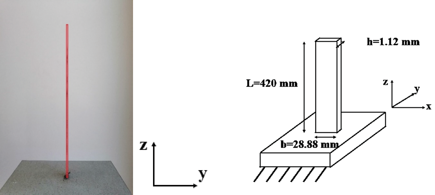
Figure 1: The cantilever beam used in the experiments
The dimensions of the used cantilever beam and the material properties are as follows:
• Elastic modulus:
• Density:
• Length:
• Width:
• Thickness:
First, an analytical model of the steel cantilever beam will be used in order to determine the modal behavior. Since the length to the width ratio L/b=14.54 and the length to the thickness ratio L/h=375 are both greater than 10, this beam can be treated as Euler Bernoulli beam. According to the analytical model discussed minutely in Inman [39] the natural frequencies (in Hz) are calculated using the Eq. (1):
where
Visual vibrating motion which occurs at different amplitude and over large frequency range hides important information such as natural frequencies, mode shapes and damping ratios. Video magnification is a methodology that aims to exaggerate the displacement in recorded video [34]. The motion in this video will be magnified, and therefore, it will be easily detected by naked eyes.
The proposed procedure in this paper starts by recording a suitable frame per second (fps) video of the vibrating structure. A free vibration system of a cantilever beam subjected to a hammer impact will be considered. Actually, an impact to a mechanical structure is a perfect impulse, which causes a constant amplitude in the frequency domain. This result shows the excitation of all vibration modes. The recorded video will be processed using the video magnification technique along the frequency interest range. This method analyses the recorded video using a phase-based motion magnification technique [34]. A displacement versus time signal of an arbitrary point on the structure is obtained, and therefore, the frequency response function (FRF) will be extracted.
The FRF presents the response spectrum of a vibrating system in response to an excitation force. It consists of the magnitude and the phase of the vibration response as function of frequency, in comparison to the excitation. An FRF is a measure of how much displacement, velocity or acceleration response a structure has at an output point, per unit of excitation force at an input point. The peaks in the FRF curve will represent the natural frequencies of the structure, and the width of the resonant peak about the peak’s center frequency is proportional to the damping ratio.
Hallal et al. [38] proved that the video magnification of the experimental measurements of such mechanical structure is accurate and reliable. A similar procedure as in [38] will be followed in this paper in order to extract the FRF of the vibrating beam.
Damping is the energy dissipation properties of a material or system under cyclic stress. Damping in mechanical systems causes the system to gradually stop moving over time. The more damping presents, the shorter the time is to stop moving. Damping can be presented in different forms such as the loss factor, damping factor or modal damping.
The following approach aims to extract damping values based on phase angle response around the resonance. Actually, the response of an undamped vibrating mechanical system is either in or out of phase with the source of excitation. Due to damping, a phase relationship between the structure and the excitation source exists. The slope of the phase angle response at resonance is defined by the damping in the system. Modal damping ration
where
Another approach, is referred to as the half power approach which is also called 3 dB method. This method uses the bandwidth at resonance, obtained from the FRF, to estimate the damping:
where:
•
•
•
Whatever the adopted approach, the FRF of the vibrating structure needs to be extracted in advance. In this paper, we will use the second approach which consists of the 3-dB method.
The measurement procedure consists first of extracting the FRF curve of the cantilever beam using the video magnification technique. And then, calculate the damping ratio of the structure using the half bandwidth method.
A hammer impact is applied at the base of cantilever beam and the transverse response is observed at an arbitrary point as shown in Fig. 2.
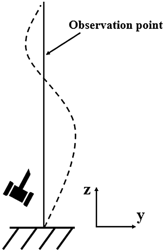
Figure 2: Vibrating cantilever beam
The applied impact to a cantilever beam is considered as a perfect impulse which causes constant amplitude in the frequency domain. A 240 fps at 1920*1080 resolution video of the transverse vibration (y direction) of the beam is recorded. The motion in this video is amplified using the motion magnification technique on a range up to 120 Hz. This maximum frequency is chosen based on the Nyquist limit. Actually, in order to avoid aliasing in the processed video, frequency range is restricted to the half of the fps rate of the recorded video. The normalized displacement of the chosen point is shown in Fig. 3. The obvious decrement of the displacement signal proves the presence of energy dissipation in the system. The frequency response function is plotted in Fig. 4.
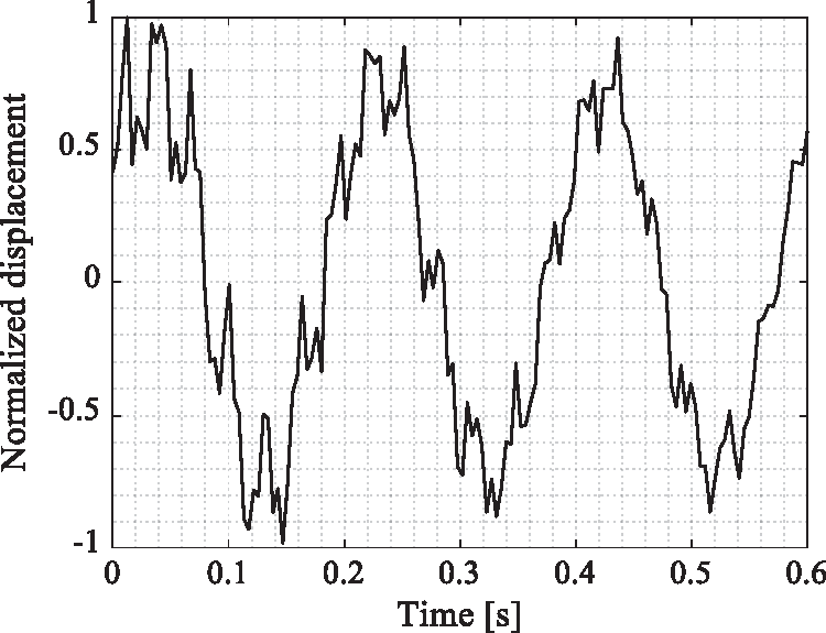
Figure 3: Normalized displacement of the chosen point
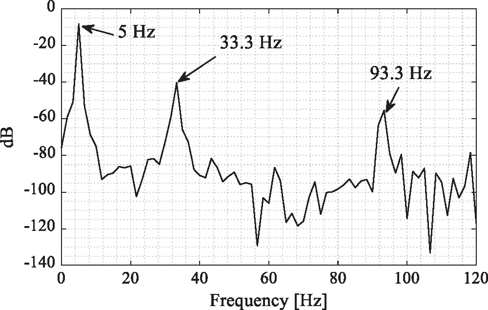
Figure 4: Frequency response function of the beams’ acceleration
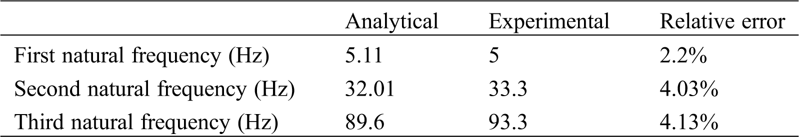
Fig. 4 shows clearly the first three natural frequencies at 5, 33.3 and 93.3 Hz, respectively. In order to verify the obtained results, the natural frequencies of the cantilever beam were calculated using an analytical model presented in Eq. (1). Tab. 1 presents the analytical and the experimental natural frequencies and their relative error. The maximum relative error is 4.13%, which is acceptable and can validate our experimental measurements.
Table 1: Natural frequencies calculated analytically and experimentally
Figs. 5–7 show a zoom of the FRF around the first, second and third peak, respectively. For each figure, the natural frequency was defined by a blue line, the -3 dB level is plotted and the associated frequencies are observed.
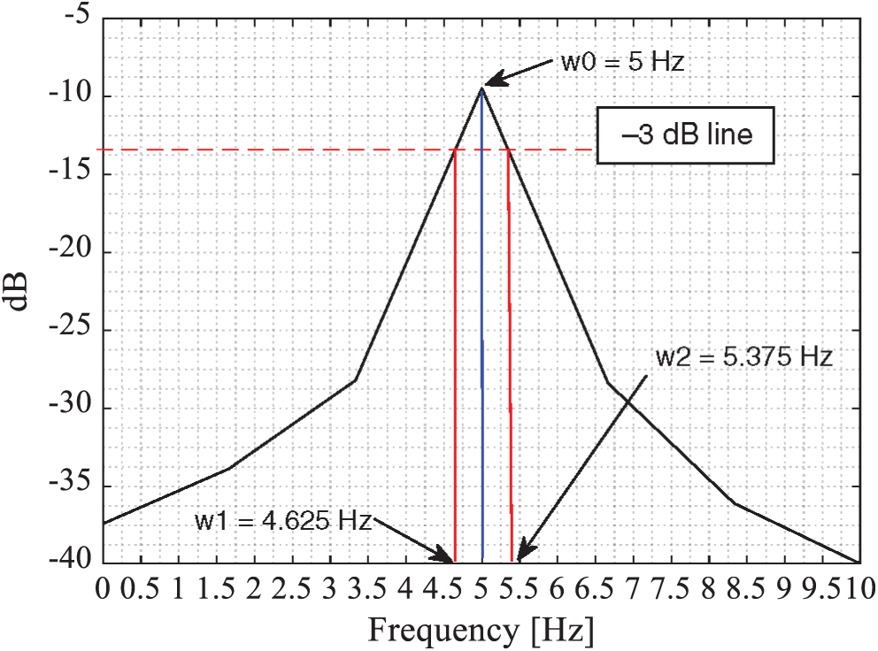
Figure 5: Zoom on the first peak of the beams’ FRF
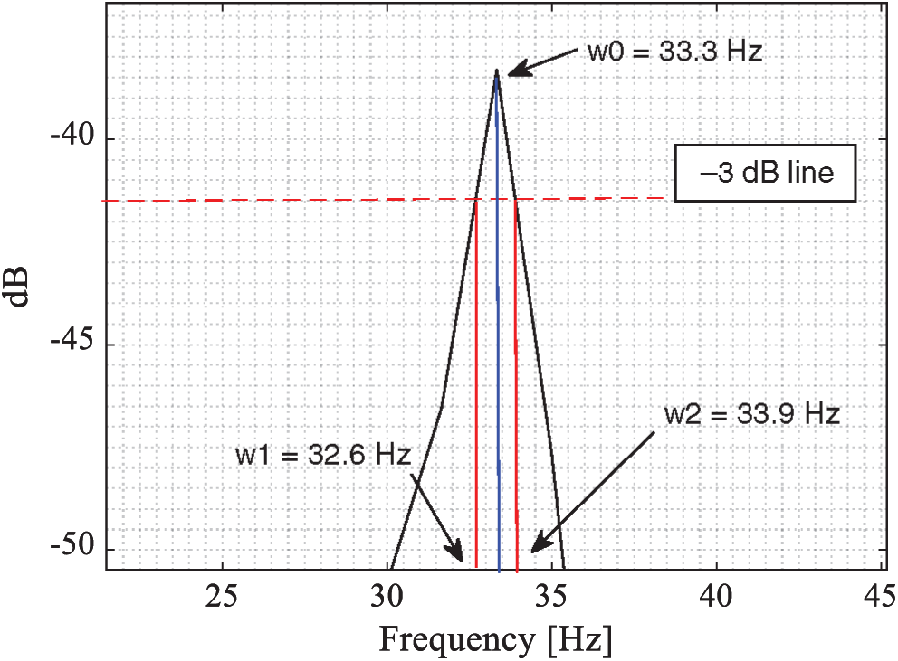
Figure 6: Zoom on the second peak of the beams’ FRF
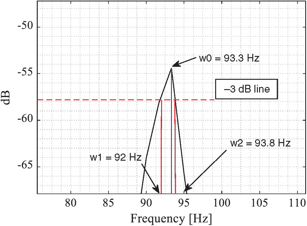
Figure 7: Zoom on the third peak of the beams’ FRF
The modal damping ratios for the first three modes are calculated using Eq. (3) as follow:
The vibration measurements are proven to be accurate based on the Euler Bernoulli beam analytical model. Therefore, the obtained modal damping ratios are considered to be accurate. The experimental measurement procedure results show that the modal damping ratio can be easily, however, accurately measured using the video magnification technique.
The experimentally measured FRF is proven accurate using an analytical model. The relative error is less than 4.2%. This will lead to believe that the proposed procedure in this paper is accurate, reliable, and low cost experimental modal damping measurement method. This procedure could be automated through smartphone application or simply a computer software. It will re-present the damping identification as simple and easy engineering application.
The FRF curve obtained using the video magnification technique is not continuous. It is broken into discrete data points at a frequency interval. As described before, this frequency interval is defined based on the number of fps of the recorded video. Actually, for high fps video, the FRF curve will fit more the real FRF curve and therefore, we expect to obtain more accurate damping ratio.
One should pay attention also if two -or more- successive natural frequencies are close to each other. In this case, the peak would appear wider and mislead the calculation. Thus, we recommend to apply the video magnification technique on a narrow band around each natural frequency. This can successfully separate the two modes influence on each other and lead to an accurate measurement of modal damping ratio.
Since the measurement is non-intrusive, and based on video recording, the proposed procedure in this paper can be applied to different mechanical structure regardless its dimension. We intend to verify this procedure on more complicated structure such as composite material in future works, like two single plates, two single plate with air void or other structures.
Funding Statement: The authors received no specific funding for this study.
Conflicts of Interest: The authors declare that they have no conflict of interest to report regarding the present study
1. Rayleigh, J. (1897). The Theory of Sound (Vol. (1 & 2)). New York: Dover Publications. [Google Scholar]
2. Duncan, P. E., Taylor, R. E. (1979). A note on the dynamic analysis of non-proportionally damped systems. Earthquake Engineering & Structural Dynamics, 7(1), 99–105. DOI 10.1002/eqe.4290070109. [Google Scholar] [CrossRef]
3. Bert, C. W. (1973). Material damping: An introductory review of mathematic measures and experimental technique. Journal of Sound and Vibration, 29(2), 129–153. DOI 10.1016/S0022-460X(73)80131-2. [Google Scholar] [CrossRef]
4. Heckl, M. (1962). Measurements of absorption coefficients on plates. Journal of the Acoustical Society of America, 34(6), 803–808. DOI 10.1121/1.1918199. [Google Scholar] [CrossRef]
5. Oliveto, G., Greco, A. (2002). Some observations on the characterization of strcutural damping. Journal of Sound and Vibration, 256(3), 391–415. DOI 10.1006/jsvi.2001.4215. [Google Scholar] [CrossRef]
6. Maia, N. M. M., Silva, J. M. M., Ribeiro, A. M. R. (1998). On a general model for damping. Journal of Sound and Vibration, 218(5), 749–767. DOI 10.1006/jsvi.1998.1863. [Google Scholar] [CrossRef]
7. Yuan, L., Agrawal, O. P. (2002). A numerical scheme for dynamic systems containing fractional Derivatives. Journal of Vibration and Acoustics, 124(2), 321–324. DOI 10.1115/1.1448322. [Google Scholar] [CrossRef]
8. Adhikari, S., Woodhouse, J. (2003). Quantification of non-viscous damping in discrete linear systems. Journal of Sound and Vibration, 260(3), 499–518. DOI 10.1016/S0022-460X(02)00952-5. [Google Scholar] [CrossRef]
9. Lancaster, P. (1961). Expressions for damping matrices in linear vibration problems. Journal of the Aerospace Sciences, 28(3), 256. DOI 10.2514/8.8949. [Google Scholar] [CrossRef]
10. Beliveau, J. G. (1976). Identification of viscous damping in structures from modal information. Journal of Applied Mechanics, 43(2), 335–339. DOI 10.1115/1.3423835. [Google Scholar] [CrossRef]
11. Minas, C., Inman, D. J. (1991). Identification of a nonproportional damping matrix from incomplete modal information. Journal of Vibration and Acoustics, 113(2), 219–224. DOI 10.1115/1.2930172. [Google Scholar] [CrossRef]
12. Chen, S. Y., Ju, M. S., Tsuei, Y. G. (1996). Estimation of mass, stiffness and damping matrices from frequency response functions. Journal of Vibration and Acoustics, 118(1), 78–82. DOI 10.1115/1.2889638. [Google Scholar] [CrossRef]
13. Pilkey, D. F. (1998). Computation of a Damping Matrix for Finite Element Model Updating (PhD Thesis). Virginia Polytechnic Institute and State University. [Google Scholar]
14. Friswell, M. I., Inman, D. J., Pilkey, D. F. (1998). Direct updating of damping and stiffness matrices. AIAA Journal, 36(3), 491–493. DOI 10.2514/2.396. [Google Scholar] [CrossRef]
15. Okuma, M., Shi, Q., Oho, T. (1999). Development of the experimental spatial matrix identification method (Theory and basic Verification with a frame structure). Journal of Sound and Vibration, 219(1), 5–22. DOI 10.1006/jsvi.1998.1821. [Google Scholar] [CrossRef]
16. Lee, J. H., Kim, J. (2001). Developmeny and validation of a new experimental method to damping matrices of a dynamic system. Journal of Sound and Vibration, 246(3), 505–524. DOI 10.1006/jsvi.2001.3670. [Google Scholar] [CrossRef]
17. Adhikari, R. (2000). Agreement on agriculture and food security: South Asian perspective. South Asia Economic Journal, 1(2), 43–64. DOI 10.1177/139156140000100204. [Google Scholar] [CrossRef]
18. Adhikari, S., Woodhouse, J. (2001). Identification of damping: Part 2, non-viscous damping. Journal of Sound and Vibration, 243(1), 63–88. DOI 10.1006/jsvi.2000.3392. [Google Scholar] [CrossRef]
19. Phani, A., Woodhouse, J. (2007). Viscous damping identification in linear vibration. Journal of Sound and Vibration, 303(3), 475–500. DOI 10.1016/j.jsv.2006.12.031. [Google Scholar] [CrossRef]
20. Arora, V., Singh, S. P., Kundra, T. K. (2009). Damped model updating using complex updating parameters. Journal of Sound and Vibration, 320(1), 438–451. DOI 10.1016/j.jsv.2008.08.014. [Google Scholar] [CrossRef]
21. Arora, V., Singh, S. P., Kundra, T. K. (2009). Finite element model updating with damping identification. Journal of Sound and Vibration, 324(3), 1111–1123. DOI 10.1016/j.jsv.2009.02.048. [Google Scholar] [CrossRef]
22. Pradhan, S., Modak, S. V. (2012). A method for damping matrix identification using frequency response data. Mechanical Systems and Signal Processing, 33(2), 69–82. DOI 10.1016/j.ymssp.2012.07.002. [Google Scholar] [CrossRef]
23. Arora, V. (2014). Structural damping identification method using normal FRFs. International Journal of Solids and Structures, 51(1), 133–143. DOI 10.1016/j.ijsolstr.2013.09.017. [Google Scholar] [CrossRef]
24. Kranjc, T., Slavič, J., Boltežar, M. (2014). A comparison of strain and classic experimental modal analysis. Journal of Vibration and Control, 22(2), 371–381. DOI 10.1177/1077546314533137. [Google Scholar] [CrossRef]
25. Park, K. T., Kim, S. H., Park, H. S., Lee, K. W. (2005). The determination of bridge displacement using measured acceleration. Engineering Structures, 27(3), 371–378. DOI 10.1016/j.engstruct.2004.10.013. [Google Scholar] [CrossRef]
26. Zhang, L., Lei, X., Jiang, J., Feng, Q. (2018). A study of the suitable measurement location and metrics for assessing the vibration source strength based on the field-testing data of nanchang underground railway. Sound & Vibration, 52(5), 22–27. DOI 10.32604/sv.2018.04058. [Google Scholar] [CrossRef]
27. Casciati, F., Fuggini, C. (2009). Engineering vibration monitoring by GPS: Long duration records. Earthquake Engineering and Engineering Vibration, 8(3), 459–467. DOI 10.1007/s11803-009-9058-8. [Google Scholar] [CrossRef]
28. Valin, J. L., Gonçalves, E., Palacios, F., Pérez, J. R. (2005). Methodology for analysis of displacement using digital holography. Optics and Lasers in Engineering, 43(1), 99–111. DOI 10.1016/j.optlaseng.2004.05.010. [Google Scholar] [CrossRef]
29. Mandal, D. D., Wadadar, D., Banerjee, S. (2018). Performance evaluation of damage detection algorithms for identification of debond in stiffened metallic plates using a scanning laser vibrometer. , Journal of Vibration and Control, 24(12), 2464–2482. DOI 10.1177/1077546316687956. [Google Scholar] [CrossRef]
30. Saravanan, K., Sekhar, A. (2012). Crack detection in a rotor by operational deflection shape and kurtosis using laser vibrometer measurements. Journal of Vibration and Control, 19(8), 1227–1239. DOI 10.1177/1077546312444770. [Google Scholar] [CrossRef]
31. Lee, J. J., Shinozuka, M. (2006). A vision-based system for remote sensing of bridge displacement. NDT & E International, 39(5), 425–431. DOI 10.1016/j.ndteint.2005.12.003. [Google Scholar] [CrossRef]
32. Sładek, J., Ostrowska, K., Kohut, P., Holak, K., Gąska, A. et al. (2013). Development of a vision based deflection measurement system and its accuracy assessment. Measurement, 46(3), 1237–1249. DOI 10.1016/j.measurement.2012.10.021. [Google Scholar] [CrossRef]
33. Wadhwa, N., Rubinsten, M., Durand, F., Freeman, W. T. (2013). Phase-based video motion processing. ACM Transactions on Graphics, 32(4), 1–10. DOI 10.1145/2461912.2461966. [Google Scholar] [CrossRef]
34. Wu, H.-Y., Rubinstein, M., Shih, E., Guttag, J., Dueand, F. et al. (2012). Eulerian video magnification for revealing subtle changes in the world. ACM Transactions on Graphics, 31(4), 1–8. DOI 10.1145/2185520.2185561. [Google Scholar] [CrossRef]
35. Rubinstein, M. (2014). Analysis and visualization of temporal variations in video (PhD Thesis). Massachusetts Institute of Technology. [Google Scholar]
36. Wadhwa, N., Rubinstein, M., Durand, F., Freeman, W. T. (2014). Riesz pyramids for fast phase-based video magnification. 2014 IEEE Int. Conf. on Computational Photography (ICCPpp. 1–10. [Google Scholar]
37. Chen, J. G., Wadhwa, N., Cha, Y. J., Durand, F., Freeman, W. T. et al. (2015). Modal identification of simple structures with high-speed video using motion magnification. Journal of Sound and Vibration, 345(1), 58–71. DOI 10.1016/j.jsv.2015.01.024. [Google Scholar] [CrossRef]
38. Hallal, J., Hammoud, M., Fakih, M., Hallal, A. (2020). Cost optimized non-contacting experimental modal analysis using a smartphone. Sound & Vibration, 54(4), 225–236. DOI 10.32604/sv.2020.011513. [Google Scholar] [CrossRef]
39. Inman, D. J. (2013). Engineering Vibrations, International Edition.Pearson Education Limited.Retrieved from https://books.google.com.lb/books?id=PPuoBwAAQBAJ. [Google Scholar]
 | This work is licensed under a Creative Commons Attribution 4.0 International License, which permits unrestricted use, distribution, and reproduction in any medium, provided the original work is properly cited. |