| Sound & Vibration |
DOI: 10.32604/sv.2021.011627
ARTICLE
Static and Dynamic Analyses of Spliced Column
Research Scholar, Civil Engineering Department, MNNIT Allahabad, Prayagraj, 211004, India
*Corresponding Author: Deepak Kumar Singh. Email: erdeepak.india@gmail.com
Received: 20 May 2020; Accepted: 23 October 2020
Abstract: The analysis of spliced column has been carried out to detect optimum location of providing splices in the column. In the present work, static and dynamic (free vibration) analyses of spliced column have been done by randomising the location of splicing. A symmetrical four storey steel framed building has been modelled, analysed and designed for loads (dead, live and earthquake loads) recommended by Indian Codal provisions using Staad.Pro. The critical column at each floor level is identified based on axial force (AF), bending moment (BM) and shear force (SF). The total 16 models of spliced columns have been designed and then modelled in a 3D CAD Design tool (SOLIDWORKS) and then imported in the finite element tool (ANSYS Workbench 14.0) for detailed analysis. The variation of stress, strain and deflection of the spliced column are shown in the form of contour. Further, the modal analysis is performed to determine the natural frequencies. The results of static and dynamic analyses are compared for each modelled spliced column to obtain the optimum location for providing splices in the column. The dynamic analysis of spliced column is of utmost importance in the region where dynamic loadings like earthquake, cyclones etc. are more frequent, and mere static analysis does not account for the safety of the structure. This study will help the engineers to select directly the optimum size and location of the splices in the column of a steel framed building.
Keywords: Column splice; finite element method; natural frequency; modal analysis; static analysis; steel framed building
Column splices are used to connect when the two individual column sections are to be lined up. Due to limitations of the size of column that can be transported. The length of the column may be more than length of the section available. Also, the area of column section required in a multi-storey building, may be different at different floor levels. Therefore, there is a need of splice connection. Splice plates are very common in joining two individual column sections at site as site welding is not preferred. Bolted connections using splice plates are more likely to be used at site because they are quicker to erect, require no weld inspection, and are economical.
Most columns do not exist in isolation but are an integral part of a frame or building. Columns are loaded by compressive AF, BM and SF, a generalised loading diagram is shown in Fig. 1. Considering the inflexion points, location of splices should be 300–1500 mm from the column ends for a 3000 mm column from structural and user view [1]. An assumption is made in the design of columns with splices that the stiffness continuity is maintained through the length of individual column and hence proper design of splices becomes more important for their efficient structural behaviour.
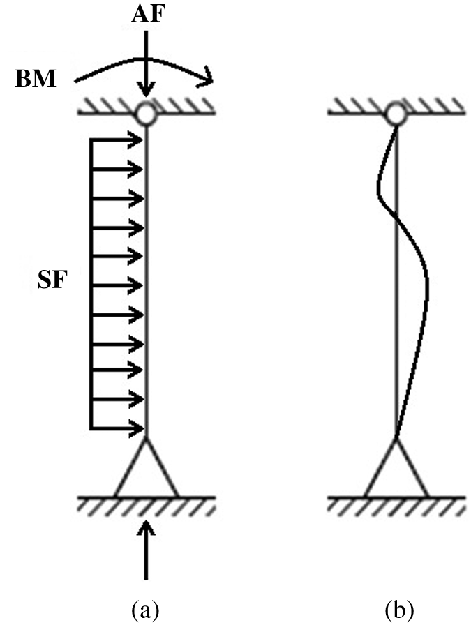
Figure 1: A generalised loading diagram (a) Loading diagram (b) Deflected shape
From elastic approach of analysis, it can be stated that the suitable location for splicing in columns subjected to double curvature bending is at the point of contra-flexure, instead of adjacent to the beam column joint. Before Northridge earthquake (1994) partial penetration welded joints were in practice for column splicing in steel structures. Several case studies in previous decades have reported numerous cases of brittle splice failure subjected to tensile loads [2,3]. Collective research efforts in the field have reported that improper detailing and low-quality weld material were the root cause which lead to brittle failure of the structure [4–8]. Similar to the other structural design problems there can be two different ways to overcome this problem, (a) increase the strength which will lead to uneconomic section, (b) reduce the strength demand of splicing by providing it at suitable location. Strength demand of the splicing in the structures subjected to seismic loading can be optimized by providing splices at locations such that static as well as dynamic response of the structure is mitigated. An approach to consider vibrational and static behaviour simultaneously is presented in the current paper and suitable locations of splicing for a 4000 mm column is discussed.
A column can fail by crushing, yielding or buckling or a combination of the latter two. The practical columns, in general are intermediate columns and are subjected to inelastic buckling. Further, splicing of column affects the overall buckling behaviour of column. Literature is available that describes the effect of splices on buckling behaviour of the column, seismic response, design methodology on building frames/columns [9–11]. To the best of author’s knowledge, none of them considers the vibrational behaviour along with structural behaviour of the spliced columns. The design criteria are discussed for the column splices [9,10] and explained the buckling behaviour of column due to splices [11]. 20 different ground motions is considered to evaluate the effect of span length on seismic demand of 4 and 9 storey building frames [12]. In the present work, free vibration analysis of spliced column is performed to evaluate the natural frequencies by providing splices at different levels in the column.
A four storey steel framed building with symmetrical plan of 18 m × 18 m having floor height of 4 m, situated in Allahabad, India was modelled with rolled ISHB 300 for columns and ISMB 250 for beams have been used in the study.
A four storey steel framed building is designed in Staad.Pro considering dead, live and earthquake loads as per the provisions of IS 875 (Part 1): 1987 [13], IS 875 (Part 2): 1987 [14] and IS 1893 (Part 1): 2002 [15], respectively. Load combinations are considered as per IS 800 : 2007 [16]. Results obtained from Staad.Pro are used to identify the point of inflexion in the critical columns of the building. For identified critical columns splicing was done at levels of 400 mm, 800 mm, 1200 mm and 1600 mm from top and bottom of the column. The splice plate connection is designed using IS 800: 2007 [16], the computer code is written in MATLAB. Further, the designed spliced columns are modelled in SOLIDWORKS and imported in ANSYS Workbench 14.0.
The spliced columns are analysed using finite element method for two conditions: 1. One of its end clamped with the other end pinned; 2. Both ends pinned, as shown in Fig. 2. The detailed steps of analysis are shown in Fig. 3.
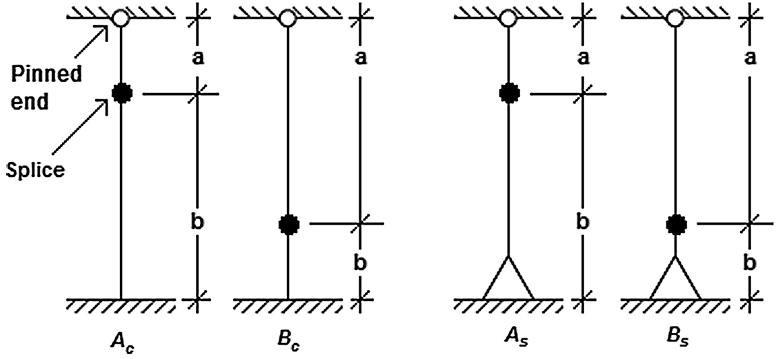
Figure 2: End conditions for spliced column
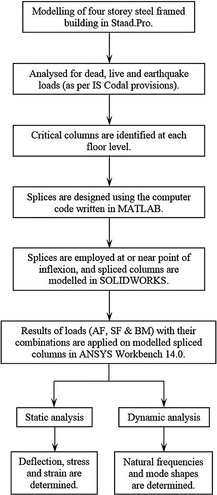
Figure 3: Flow diagram of analysis
A convergence study has been carried out to determine the optimum mesh size. An un-spliced column (ISHB 300) of length 4000 mm is modelled and results are plotted for von Mises stress. It is observed that the stresses converge for 10 mm mesh size, and hence 10 mm mesh is considered for further analysis.
SOLID187 (10 noded tetrahedral 3-D element with three degree of freedom at each node), is used to mesh column, nut and bolts [17] and SHELL181 (4 noded 2-D element with six degree of freedom at each node) is used to mesh plates (flange and web plate) of the spliced column.
Altogether 364379 nodes and 186072 elements have been generated when the spliced columns are discretised with mesh size of 10 mm.
Static and dynamic analyses have been carried out for the spliced columns. Static analysis comprises of evaluation of von Mises stress, strain and deflection after application of different combinations of BM, AF and SF. Modal analysis is used to determine the natural frequency and mode shape of the spliced columns.
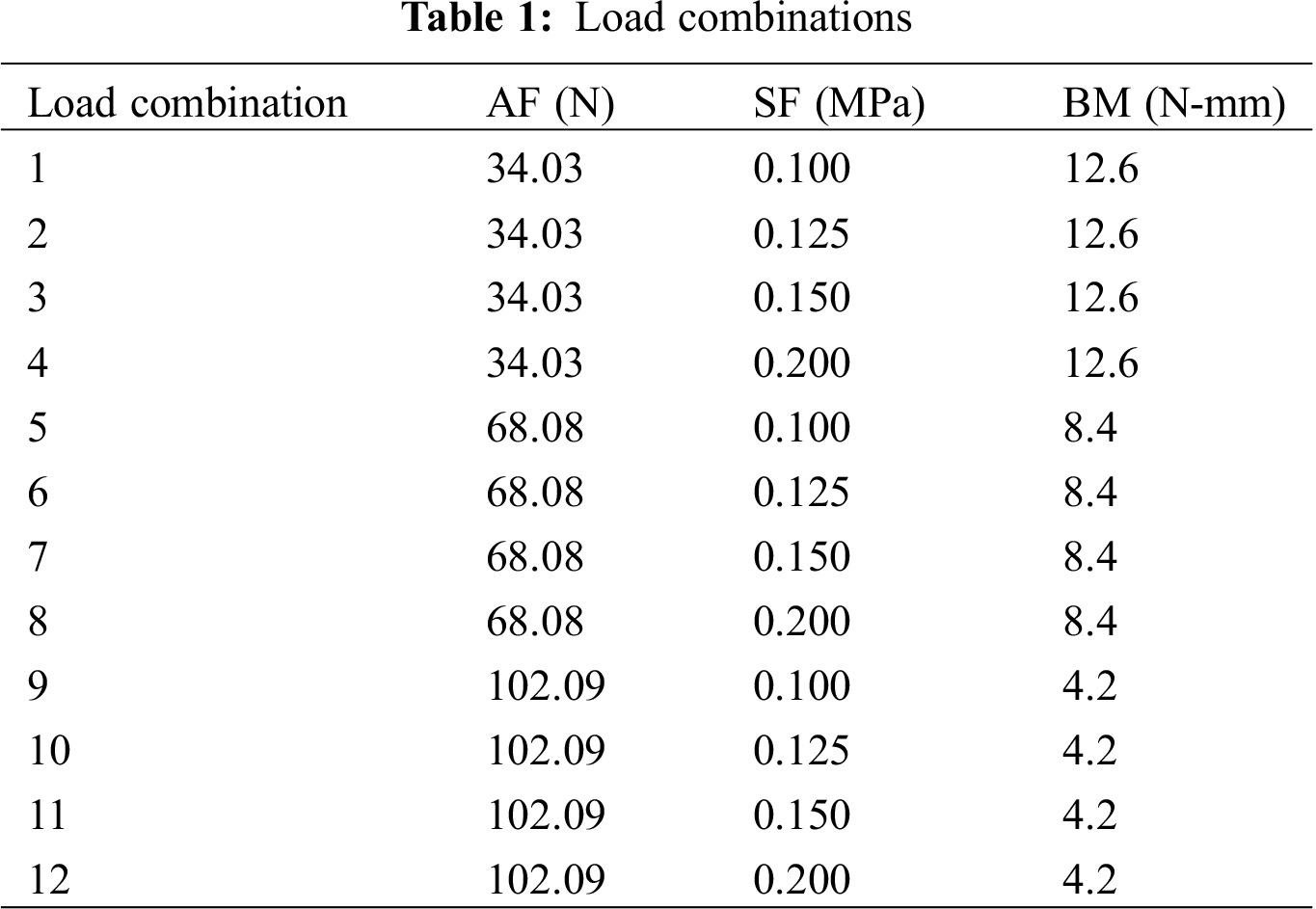
Interaction formula and design shear strength formulas specified in IS 800: 2007 [16] (Eqs. (1) and (2) are used to check the adequacy of the column design. The AF and SF is applied on the cross section and face of the flange respectively in the form of pressure in FEA. The parametric study has been carried out based on the above stated criteria for the different load combinations of the forces as presented in Tab. 1.
where,
The contour of stress, strain and deflection with (i) spliced at 1200 mm from top and bottom is clamped, (ii) spliced at 1200 mm from bottom and bottom is clamped, (iii) spliced at 1200 mm from top and bottom is pinned and (iv) spliced at 1200 mm from bottom and bottom is pinned are shown in Fig. 4.
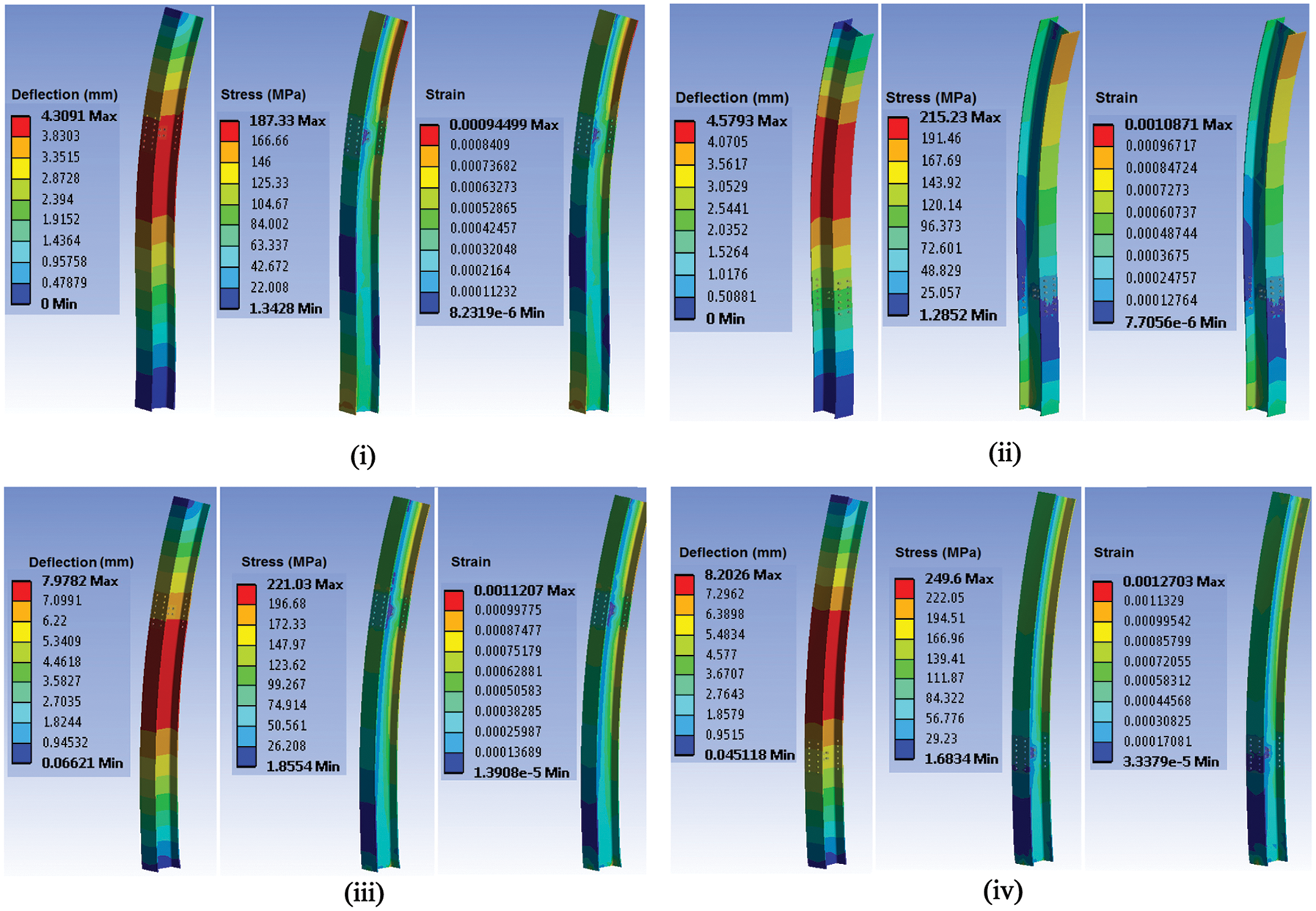
Figure 4: Contours of deflection, stress and strain (i) spliced at 1200 mm from top and bottom is clamped (ii) spliced at 1200 mm from bottom and bottom is clamped (iii) spliced at 1200 mm from top and bottom is pinned (iv) spliced at 1200 mm from bottom and bottom is pinned
The first three mode shapes of the un-spliced column, 4000 mm in length, and the other spliced at 1200 mm from top and bottom of the column are shown in Figs. 5–7, respectively. These are based on the free vibration equation (Eq. (3)). The natural frequencies of first three modes for these columns are presented in Tabs. 2 and 3.
where,
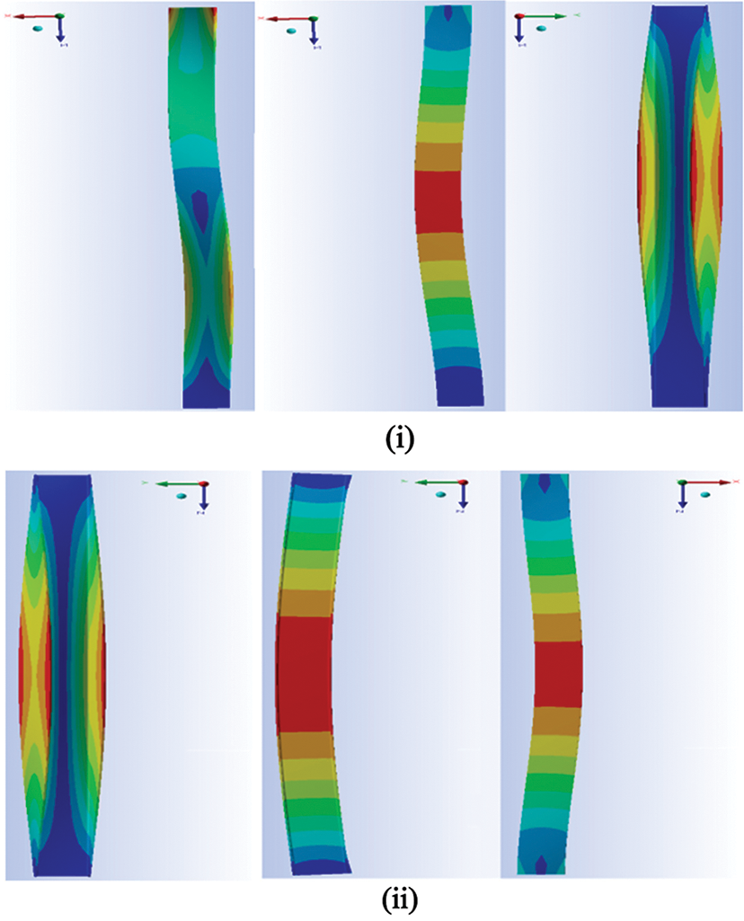
Figure 5: Mode shapes of un-spliced column (4000 mm) (i) clamed at bottom (ii) pinned at bottom
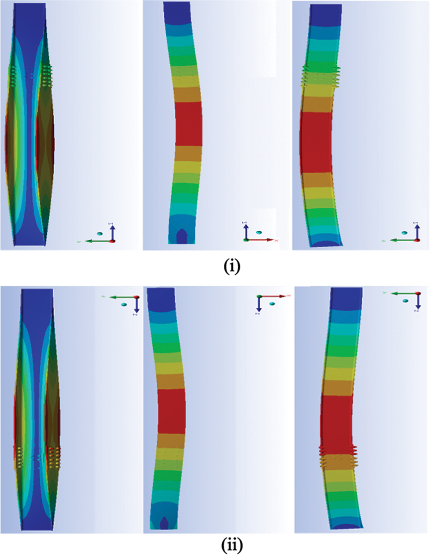
Figure 6: Mode shapes of spliced column when bottom is clamped (i) spliced at 1200 mm from top (ii) spliced at 1200 mm from bottom
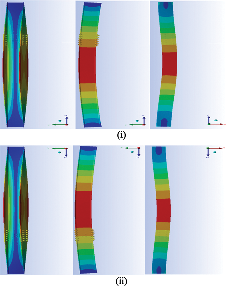
Figure 7: Mode shapes of spliced column when bottom is pinned (i) spliced at 1200 mm from top (ii) spliced at 1200 mm from bottom
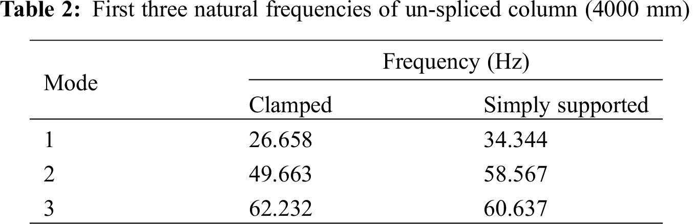
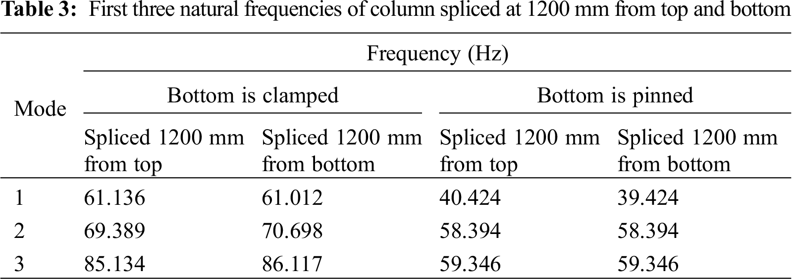
It is observed that the first three modal frequencies increase significantly when columns are spliced and the difference decreases for the higher modes. The increase in frequency is quite high for end condition camped than that for simply supported.
It is found that the load combinations 4, 8 and 12 are critical so the variation of stress, strain, deflection and first modal frequency are plotted for 16 models considering these load combinations using different scaled values for all end conditions.
It may be observed from Figs. 8 and 9 that the maximum frequency (Mode 1) for all the 16 models (both clamped and simply supported) do not occur where stress and deflection are minimum.
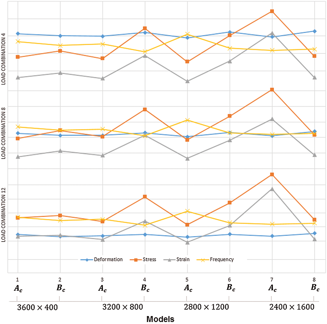
Figure 8: Variation of deflection, stress (scaled = * 0.02), strain (scaled = * 3000) & frequency for load combination 4, 8 and 12 with clamped end conditions
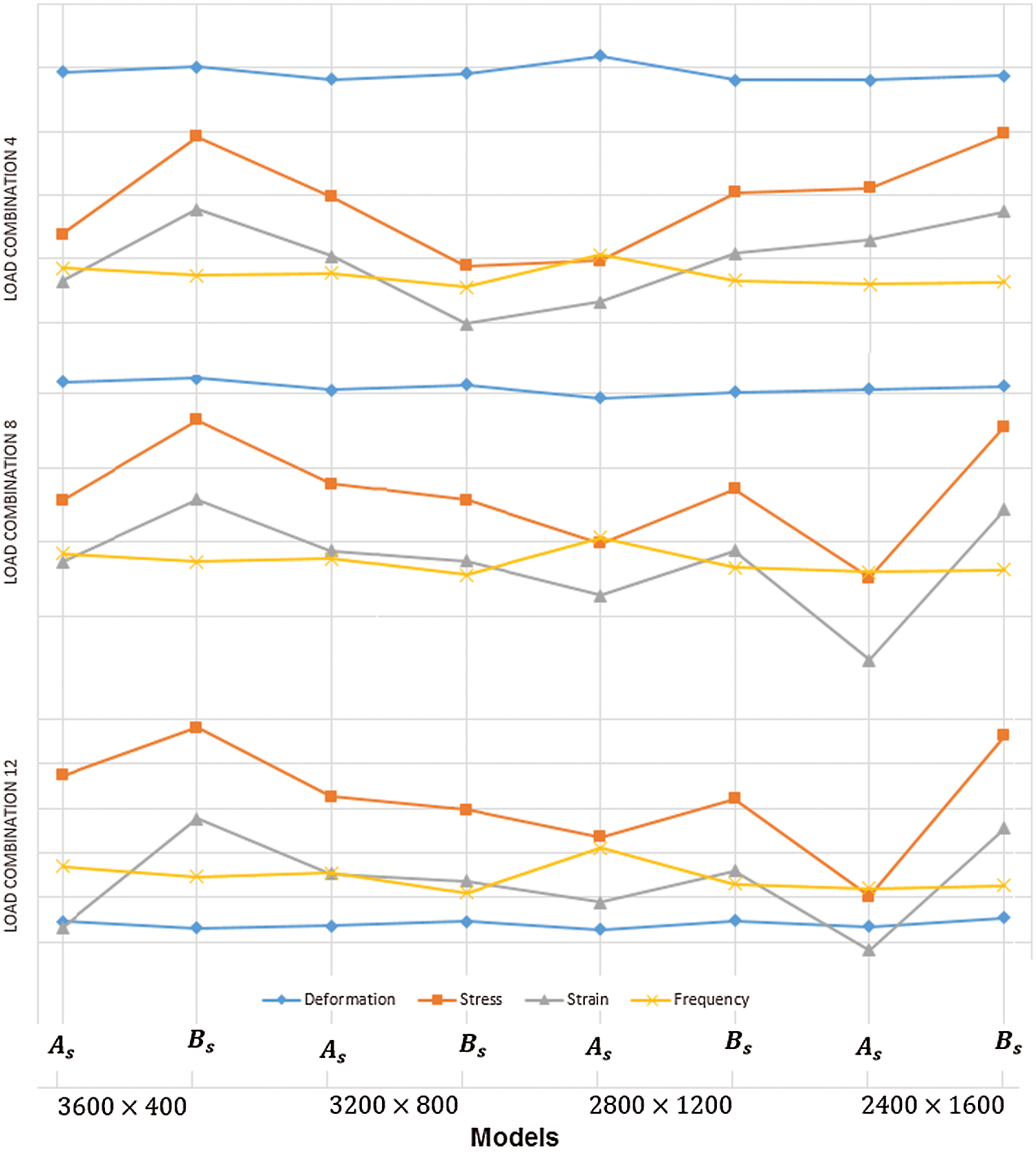
Figure 9: Variation of deflection, stress (scaled = * 0.02), strain (scaled = * 3000) and frequency for load combination 4, 8 and 12 with simply supported end conditions
Column sections up to 10 m length can be transported easily to the site for construction, so there is no need of splicing the bottom most column lengths. Splices may be needed in third or fourth stories in the 4 storey steel framed buildings. The vibrational behaviour is very significant for the industrial buildings, buildings near railway tracks, metro station buildings, seashore structures and structures in seismic areas, etc. The vibrational and structural behaviour is considered together to obtain the optimum location for the placement of splices in the column. And it was found that the vibrational behaviour do affects in predicting the splice locations. After analysing both structural and vibrational behaviour by placing splices at four different position. It can be concluded that splicing columns at 1200 mm from top and bottom of the column, the maximum frequency was found in the Ist mode amongst 16 models. So, in higher seismic zone when dynamic/vibrational forces are dominating, column with splicing at 1200 mm from top and bottom is most suitable. If structure is situated in lower seismic zone or if static loads are dominant, it is recommended to splice column at 800 mm from top and bottom. The present helps and motivates to numerically decide the optimum position of splicing in the column. In future, a generalised program may be developed to find the size of splices and position of splicing. This study motivates the researcher to carry out dynamic analysis along with the static analysis for the region where dynamic loads are dominant.
Funding Statement: The author received no specific funding for this study.
Conflicts of Interest: The author declares that they have no conflicts of interest to report regarding the present study.
1. Duggal, S. K. (2019). Limit state design of steel structures. India: McGraw-Hill Book Company. [Google Scholar]
2. Fisher, J. W., Pense, A. W. (1987). Experience with use of heavy W shapes in tension. American Institute of Steel Construction Engineering Journal, 24(2), 63–77. [Google Scholar]
3. Bruneau, M., Mahin, S. A. (1991). Full scale tests of butt welded splices in heavy rolled steel sections subjected to primary tensile stresses. American Institute of Steel Construction Engineering Journal, 28(1), 1–17. [Google Scholar]
4. SAC Joint Venture (2000). Recommended seismic evaluation and upgrade criteria for existing welded steel moment-frame buildings. Report No. FEMA-351, 1. Federal Emergency Management Agency, Washington DC. [Google Scholar]
5. SAC Joint Venture (2000). Recommended post-earthquake evaluation and repair Criteria for welded steel moment-frame buildings. Report No. FEMA-351, 2. Federal Emergency Management Agency, Washington DC. [Google Scholar]
6. SAC Joint Venture (2000). A policy guide to steel moment-frame construction. Report No. FEMA-351, 3. Federal Emergency Management Agency, Washington DC. [Google Scholar]
7. SAC Joint Venture (2000). State of the art report on base metals and fracture. Report No. FEMA-351, 4. Federal Emergency Management Agency, Washington DC. [Google Scholar]
8. SAC Joint Venture (2000). State of the art report on welding and inspection. Report No. FEMA-351, 5. Federal Emergency Management Agency, Washington DC. [Google Scholar]
9. Coelho, A. M. G., Bijlaard, F. S. K. (2008). Requirements for the design of column splices. Stevin Report. Delft University of Technology. [Google Scholar]
10. Coelho, A. M. G., Simão, P. D., Bijlaard, F. S. K. (2010). Stability design criteria for steel column splices. Journal of Constructional Steel Research, 66(10), 1261–1277. [Google Scholar]
11. Simão, P. D., Coelho, A. M. G., Bijlaard, F. S. K. (2012). Influence of splices on the buckling of columns. International Journal of Non-Linear Mechanics, 47(7), 806–822. [Google Scholar]
12. Akbas, B., Doran, B., Sabol, T. A., Seker, O., Toru, P. et al. (2014). Effect of various span lengths on seismic demand on column splices in steel moment frames. Engineering Structure, 70, 94–105. [Google Scholar]
13. Indian Standard (IS) (1987). IS 875 (Part 1). Code of practice for design loads (other than earthquake) for buildings and structures: Dead loads. New Delhi, India: Bureau of Indian Standards. [Google Scholar]
14. Indian Standard (IS) (1987). IS 875 (Part 2). Code of practice for design loads (other than earthquake) for buildings and structures: Live loads. New Delhi, India: Bureau of Indian Standards. [Google Scholar]
15. Indian Standard (IS) (2016). IS 1893 (Part 1). Indian standard criteria for earthquake resistant design of structures. New Delhi, India: Bureau of Indian Standards. [Google Scholar]
16. Indian Standard (IS) (2007). IS 800. Code of practice for General construction in steel. New Delhi, India: Bureau of Indian Standards. [Google Scholar]
17. Mostafa, M., Tawfik, T. (2016). Crack detection using mixed axial and bending natural frequencies in metallic Euler-Bernoulli beam. Latin American Journal of Solids and Structures, 13(9), 1641–1657. [Google Scholar]
 | This work is licensed under a Creative Commons Attribution 4.0 International License, which permits unrestricted use, distribution, and reproduction in any medium, provided the original work is properly cited. |