| Sound & Vibration |
DOI: 10.32604/sv.2021.015705
ARTICLE
Modal Control of Cantilever Beam Using a Gyrostabilizer
1Department of Mechanical Engineering, Karadeniz Technical University, Trabzon, 61080, Turkey
2Department of Mechanical Engineering, Gümüşhane University, Gümüşhane, 29100, Turkey
3Department of Mechanical Engineering, Texas Tech University, Lubbock, 79409, USA
*Corresponding Author: Faruk Ünker. Email: farukunker@gumushane.edu.tr
Received: 07 January 2021; Accepted: 22 May 2021
Abstract: In this paper, an experimental model of a horizontal cantilever beam with a rotating/oscillating attached to the shaker for harmonic excitation at the one end and a gyrostabilizer at the other end is built to verify the equations of the Lagrangian model. The primary focus of the study was to investigate the parameters of excitation amplitude, natural frequency, rotating mass (disk mass), and disk speed of gyro that would minimize the amplitude of the beam to identify these effects. Numerical and experimental results indicate that the angular momentum of the gyrostabilizer is the most effective parameter in the reduction of beam displacement.
Keywords: Cantilever beam; rotating tip mass; gyrostabilizer; roll motion; modal control; flexural vibration
Notation
| g | the gravitational acceleration |
| E | Young’s modulus |
| h | cantilever beam thickness |
| b | width of the cantilever beam |
| L | length of the cantilever beam |
| I | geometrical moment of inertia of the cantilever beam |
| It | mass moment of inertia of free end of the cantilever beam |
| c | equivalent coefficient of torsion damping of bearing on gyro |
| cb | equivalent coefficient of dissipation of cables on beam |
| k | stiffness of torsion spring of gyro |
| m | mass of rotating disk |
| Mt | the weight of the all gyro mechanism excluding flywheel |
| T | total kinetic energy of system |
| Tgyro | the kinetic energy of gyro |
| D | total dissipation energy of system |
| V | total potential energy of system |
| (X, Y, Z) | the coordination in the world coordination system |
| u | the horizontal displacement of beam at the free end |
| v | the vertical displacement of beam at the free end |
| θ | the precession angle of gyro |
| φ | the orientation angle of beam |
| s | arc-length of beam |
| ψ | the first mode of the shape function of beam |
| z | the harmonic base excitation |
| z0 | the amplitude of the base excitation |
| ω | the angular frequency of base excitation |
| ωn | the natural frequency of beam |
| Ip | the rotary inertia of disk |
| Io | the mass moment of inertia of disk |
| Ifx, Ify, Ifz | the principal moments of inertia of gyroscope (Taken at the center of mass of the gimbal) |
| Ω | the rotational velocity of disk |
The application of rotating and oscillating types of vibration control systems can be found in several systems such as space structures, robotics, aircraft, ships, etc. [1–4]. Due to a wide variety of uses, several studies and investigations have been performed on non-linear dynamics of rotating and oscillating tip mass systems used as vibration control for the past several years. Studies are still continuing with new published materials on this interesting and multi parameter topic of vibration control [5–7]. Hence, several studies have been performed both theoretically and experimentally on non-linear dynamics of a beam with rotating and oscillating tip mass under variations of parameters subject to sinusoidal and random excitation. Most common used in these studies is the Bernoulli-Euler beam model, which includes a vertical cantilever beam with a concentrated tip mass at one end [8]. However, Timoshenko theory is considered to be an improvement since shear deformation and rotational inertia of the beam are also taken into account [9,10].
Currently, a large number of researchers remain focused on flexible structures with passive dynamic vibration absorbers such as rotating mass (flywheel), beam, liquid, pendulum, etc., used for several engineering applications [11–14]. The passive vibration absorbers to be effective and desirable as a vibration control device due to its simplicity and lower cost. The dynamic behavior of a beam–tip mass-pendulum system was investigated to determine the autoparametric interaction between the beam and pendulum frequencies effecting beam displacement under sinusoidal excitation [15]. An orientable flexible beam with a tip mass and passive pendulum attached to the tip mass was researched under sinusoidal excitation experimentally [16]. Also, the passive vibration absorber is activated by the structural motion without any external input to reduce displacement which in turn makes the system beneficial [17]. Although having desirable results, passive vibration control apparatuses have their limitations and require activation energy from the system and requires a starting oscillation in order to provide energy for oscillating the pendulum. This limitation of passive vibration control systems have lead the need and development of active vibration control systems, hence the area of high interest and research work has been concentrated towards active systems. However, active control systems require external energy/power input to operate the vibration control apparatus, hence active vibration absorbers are more complex, unreliable and un-robust due the requirement to control internal hardware such as sensors and control equipment that are not present in passive systems [18].
Meanwhile, several researches have been investigating different types of vibration control apparatuses in range from simple to complex; for instance the use of gyrostabilizers, being a complex yet effective vibration control apparatus is used for several engineering applications such as stabilization of wheeled vehicles [19,20] and wind induced vibrations [21]. The apparatus including the gyrostabilizer used in this study supplies the external energy requirement by an electric motor in a rotating gimbal to the flywheel (disk mass). The remaining energy provided to the apparatus comes from the momentive motion of gyrostabilizer and is therefore classified as a passive control apparatus under several engineering studies and applications. The gyrostabilizer is effective for bending moments rather than shear forces due to the utilization of gyroscopic moment to reduce or eliminate undesirable motion [22–24]. Therefore, compared to conventional active mass dampers for vibration suppression, the gyrostabilizers are much effective in a larger frequency range and represent a weight and volume saving due to the angular momentum of the gyroscope [11].
For the modeling of antennas, robotic manipulators, appendages of aircrafts, spacecrafts or vehicles, etc., beams carrying a tip mass with (or without) rotary inertia can be used. In this study, the vibration control results of a horizontal cantilever beam with a rotating/oscillating tip mass (gyrostabilizer) at one end and harmonic excitation at the other end has been investigated through theoretical and experimental methods. Parameters of excitation amplitude, natural frequency of the beam tip mass system, rotating mass (disk mass) and disk speed that would minimize the amplitude of the beam were identified alongside the effects to the system. The apparatus included an oscillated mass connected to the free end of the beam with a small ball bearing and disk with DC electrical motor mounted to the oscillating tip, while the other end was mounted to a shaker.
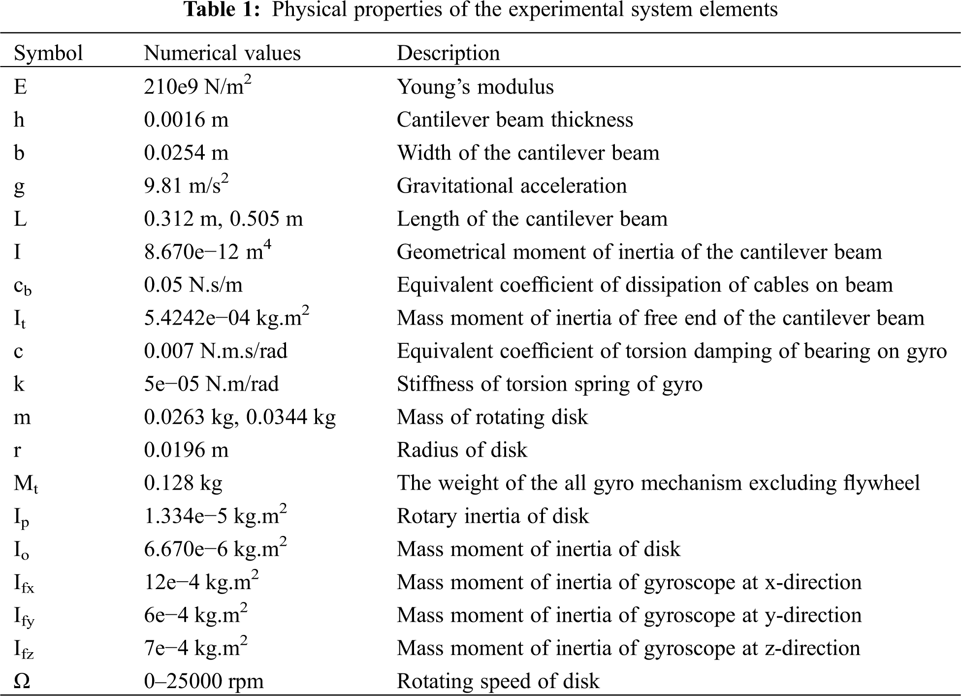
Experimental studies were performed on an apparatus set-up in the Mechanical Engineering Department laboratory at Texas Tech University as seen in Fig. 1. For accurate results both physical properties of the apparatus as well as mechanical properties were optimized as show in Tab. 1. On the experimental apparatus the gyrostabilizer is mounted to one end of the cantilever beam, while the other end of the cantilever beam is mounted to the shaker; this provides vertical displacement in harmonic form with different amplitudes and forcing frequencies to the cantilever beam.
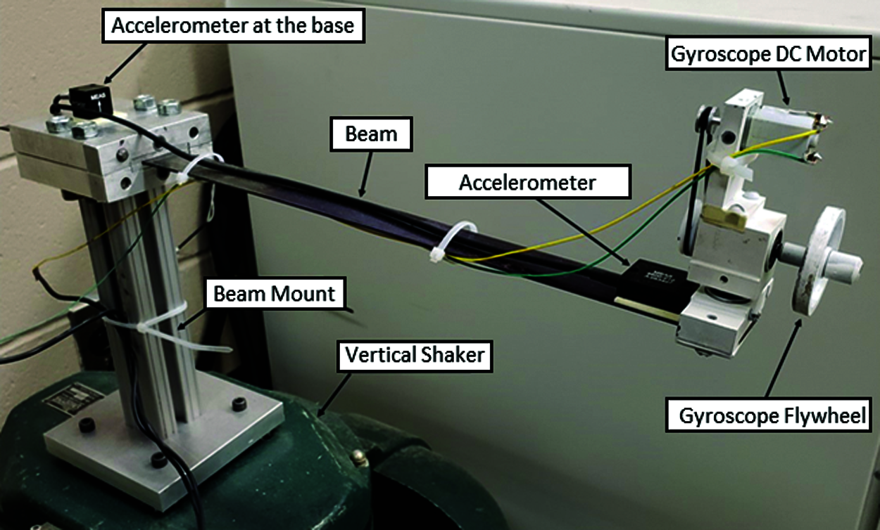
Figure 1: Photography of the experimental system
The experimental apparatus set-up consists of a waveform generator (Siglent SDG1025), a vertical/horizontal shaker (Calidyne Inc., Model A88), two accelerometers (TE Connectivity, 4623M3-010-040, 4600-010-060) and MATLAB software (National Instruments, USB 6343) as seen in a schematic diagram form shown in Fig. 2. The excitation waveform generator was used to set up parameters such as forcing amplitude, range of forcing frequency of the cantilever beam system and linear sweep rate of forcing frequency as small as 0.001 Hz/s. The sweep rate of 0.001 Hz/s was kept stable for all forcing frequency ranges during each sweeping frequency experiment. The shaker provided forcing amplitude and forcing frequency coming from the waveform generator to the end of the cantilever beam connected to the shaker. Accelerometers were used to measure the forcing excitation amplitude for closed loop control and displacement of the cantilever beam next to the tip mass location. MATLAB software collected cantilever displacement data in graphical form with respect to sweeping forcing frequency in real time.
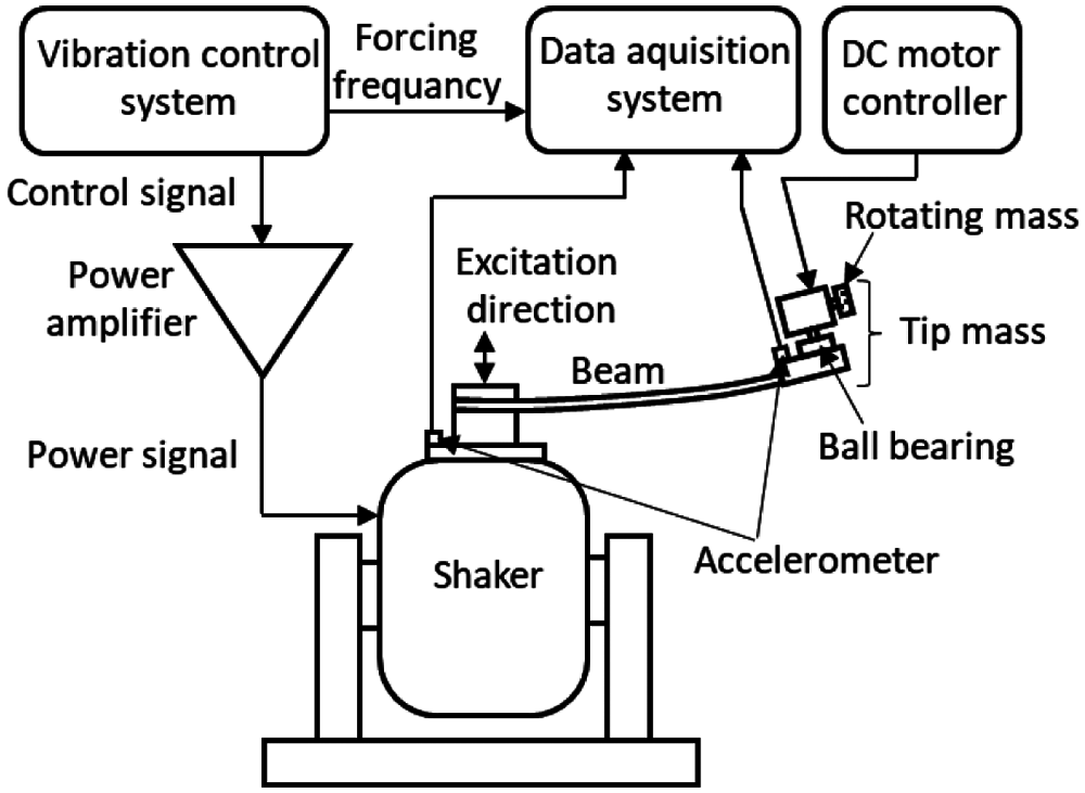
Figure 2: Schematic diagram of the experimental system
Experimental studies were performed for different parameters such as length of the cantilever beam system, rotating mass, rotating speed of the mass and forcing amplitude. In order to determine the relationship between varying parameters, one parameter was changed and the rest of were kept stable for each experimental run.
The Euler-Bernoulli beam theory based on thin cantilever beams was used to obtain governing equations of motion of the cantilever beam with a tip mass. Shear deformation and rotational inertia of the beam were neglected from the governing equations due to thin cantilever beam assumption (L/h > 20). In the governing equation, the parameters of the cantilever beam mass density ρ, cross-sectional area A, Young’s modulus E and moment of inertia.
The mathematical model of the cantilever beam with tip mass (gyrostabilizer) was derived through the displacement model of the cantilever as shown in Fig. 3. As seen from the Figure, the displaced cantilever beam with length (L) and gyrostabilizer mass (Mt) at the free end is subject to a harmonic base excitation (z(t)) from the opposing end, which is attached to the shaker. In the equation models used for these experiments, the denotations are as follows: arc-length (s), harmonic excitation (z = z0cos(ωt)) with varying forcing frequencies (ω) and forcing amplitudes (z0). Due to the beam displacement, horizontal and vertical displacements at the free end and orientation angle were denoted as (u), (v) and (φ), respectively.
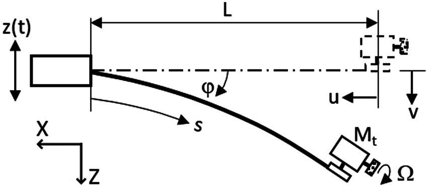
Figure 3: Model of the displaced form of cantilever beam with gyrostabilizer tip mass
The gyrostabilizer mass (Mt) has a rotating mass (m) within the structure consisting of a DC electrical motor which controls rotational speed of the mass (m) about the geometric axis as shown in Fig. 4. Rotational (angular) speed of the mass (m) and oscillation of the gyrostabilizer mass (Mt) are denoted by Ω and θ, respectively. The ball bearing shows resistance from the torsional spring (kθ) and damper (c θ˙) effect due to the gyrostabilizer mass oscillation generated by rotational mass.
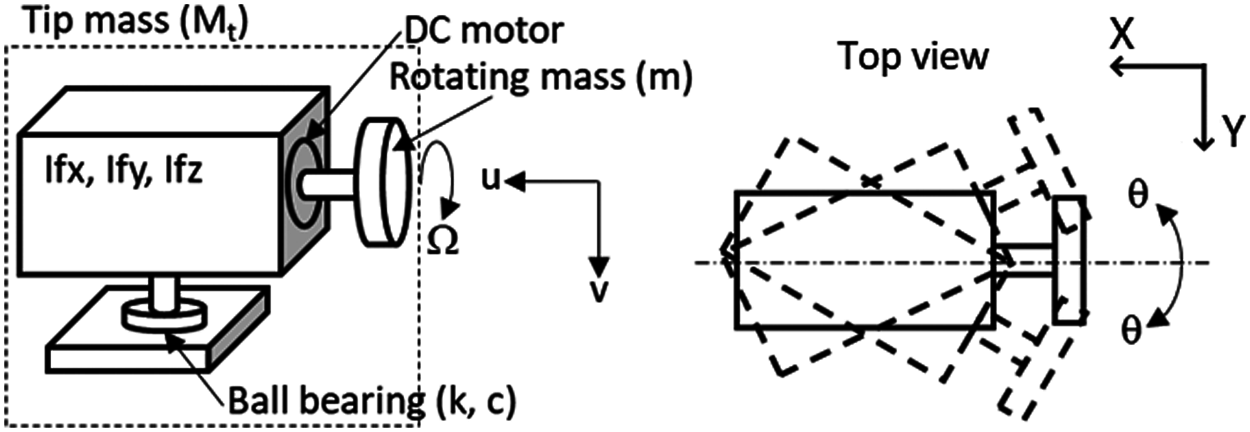
Figure 4: Gyrostabilizer model
The kinetic energy equation of the cantilever beam with gyrostabilizer tip mass can be written in the form shown below in Eq. (1), derived from the free-body motion diagram in Fig. 3. In the equation, u(s, t) and v(s, t) indicate displacements along the inertial directions of the beam with respect to arc-length and time (dot is indicative of derivative with respect to time t).
The kinetic energy of the gyrostabilizer can be expressed in the form of Eq. (2), derived from the free-body motion diagram in Figs. 3 and 4.
The potential energy of the cantilever beam with gyrostabilizer can be defined in the form of Eq. (3).
The dissipation function (D) is defined in the form of Eq. (4).
Orientation angle of the beam is defined in the form of Eq. (5) [25–27] which indicates a partial derivative with respect to arc-length (s) along the beam.
The displacement of the beam is expressed in Eq. (6) [25,26] with mathematical manipulation and eliminating terms of higher order.
From Eq. (5) the following equation are obtained:
Derivative of Eq. (7) is expressed as:
Beam deformation with respect to arc-length and time can be expressed by accepting the first mode of the shape function ψ(s) [27] and by acknowledging the tip mass being significantly larger than the beam mass. By using binomial expansion and mathematical manipulation, Eqs. (6)–(8) have been expanded into the following equations:
If
Therefore, the kinetic energy of the system can be defined by using the above equations, while the transverse displacement (v) at the free end can be expressed as in Eq. (11).
The potential energy of the system in Eq. (3) can be defined in terms of the transverse displacement (v) at the free end can be expressed as in Eq. (12).
Constants G1 through G9 used in the above equations can be expressed as in Eq. (13).
3.1 Equation of Motion of the Beam at the Free End
Energy method has been used to obtain equations of motion for the cantilever beam with gyrostabilizer tip mass. The kinetic energy (Eq. (11)), dissipation function (Eq. (4)) and potential energy (Eq. (12)) were substituted into Lagrange’s Equation (Eq. (14)) and after mathematical manipulation, the beam equation has taken the following form as seen in Eq. (15):
3.2 Equation of Motion of Gyrostabilizer
The energy method was also used to obtain equations of motion for the gyrostabilizer. The kinetic energy (Eq. (11)), dissipation function (Eq. (4)) and potential energy (Eq. (12)) were substituted into Lagrange’s Equation (Eq. (16)) and after mathematical manipulation, the gyrostabilizer equation has taken the following form as seen in Eq. (17):
Theoretical and experimental studies were performed for varying parameters such as the natural frequency of the cantilever beam system, rotating mass, rotating speed of the mass and forcing amplitude. In order to accurately determine the relationship between the parameters, one parameter was changed as the rest were kept stable for each individual test.
Cantilever beam with gyrostabilizer system frequency response curves were obtained theoretically and experimentally for the following parameters of natural frequency of the system (ωn), rotating mass (m), rotating mass speed (Ω), and forcing amplitude z(t). All theoretical and experimental results were plotted graphically with respect to forcing frequency vs. beam tip-mass amplitude and rotating mass speed versus maximum beam amplitude at tip.
Theoretical and experimental frequency response curves of the beam with gyrostabilizer tip-mass system were plotted graphically as seen in Figs. 5 and 7 with constant parameters of the system natural frequencies (ωn = 2.12 Hz and ωn = 4.13 Hz), forcing amplitude (z0 = 1.3 mm) and rotating mass (disk mass) (m = 0.0344 kg) and variable rotating mass speeds of Ω = 0, 11250 and 25000 rpm. The maximum amplitude of the system was observed at the resonance frequency when the rotating mass speed was equal to zero (non-active gyrostabilizer); as the rotational mass was initiated with speed (active gyrostabilizer), the maximum amplitude of the system was dramatically reduced, while the natural frequency of the system was increased (shifted to the right) due to the inertia moment of the gyrostabilizer. Hence, theoretical and experimental results concluded in agreement with all parametric factors displayed in Figs. 5 and 7.
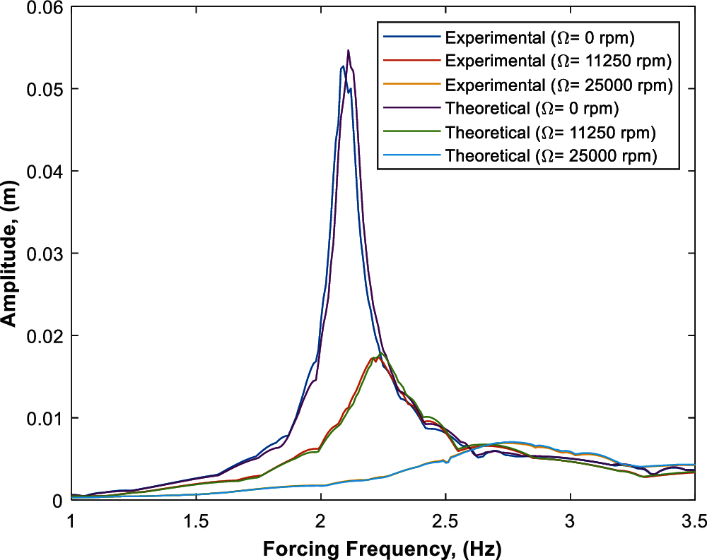
Figure 5: Theoretical and experimental frequency response curves of the beam with respect to parameters of Ω = 0 rpm, 11250 rpm and 25000 rpm and constant parameters of z0 = 1.3 mm, m = 0.0344 kg and ωn = 2.12 Hz
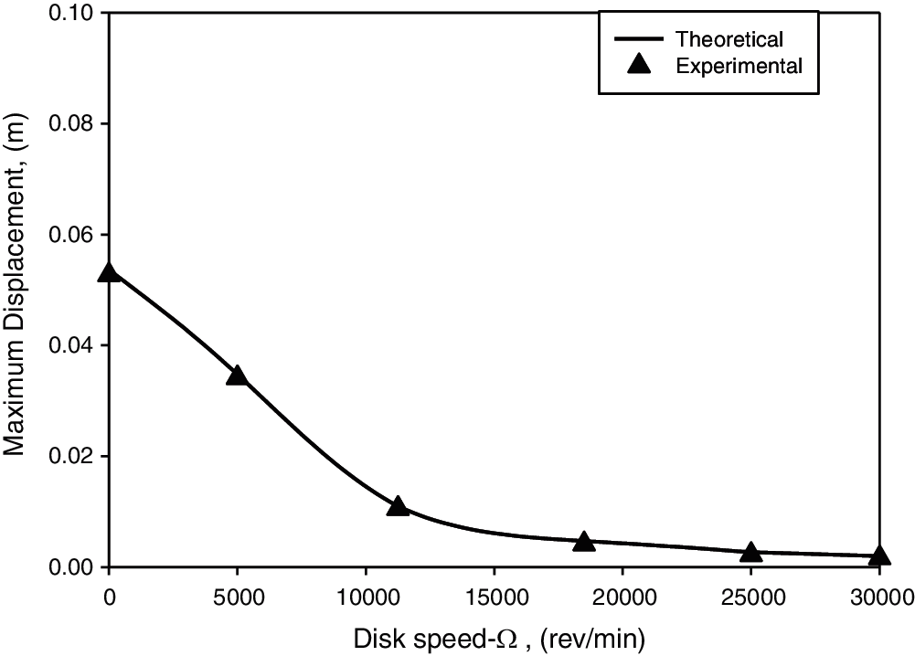
Figure 6: Disk speed vs. beam maximum displacement with parameters of ω = 2.12 Hz, m = 0.0344 kg and z0 = 1.3 mm
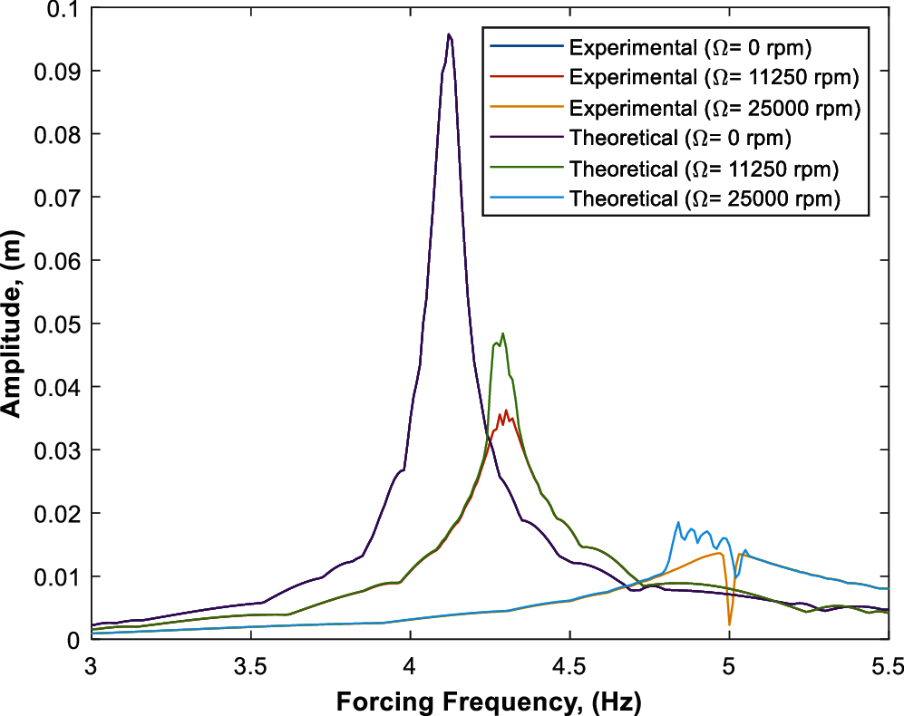
Figure 7: Theoretical and experimental frequency response curves of the beam with parameters of Ω = 0 rpm, 11250 rpm, 25000 rpm, z0 = 1.3 mm, m = 0.0344 kg and ωn = 4.13 Hz
The relationship between rotational mass speed and maximum amplitude of the system (amplitude at resonance frequency) with two different natural frequencies of ωn = 2.12 Hz and 4.13 Hz are shown in Figs. 6 and 8, respectively. As seen from both figures, the amplitude of the system was significantly reduced up to a certain rotational mass speed by the gyrostabilizer, however the amplitude of the system was not highly reduced after a certain speed of the rotational mass such as 12500 rpm with a natural frequency of 2.12 Hz and 25000 rpm with a natural frequency of 4.13 Hz. These two rotational speeds can be described as the optimum rotational speeds with respect to their related natural frequencies due to the amplitude of the system not being effected significantly beyond these points. Both theoretical and experimental results concluded in agreement with results displayed in Figs. 6 and 8.
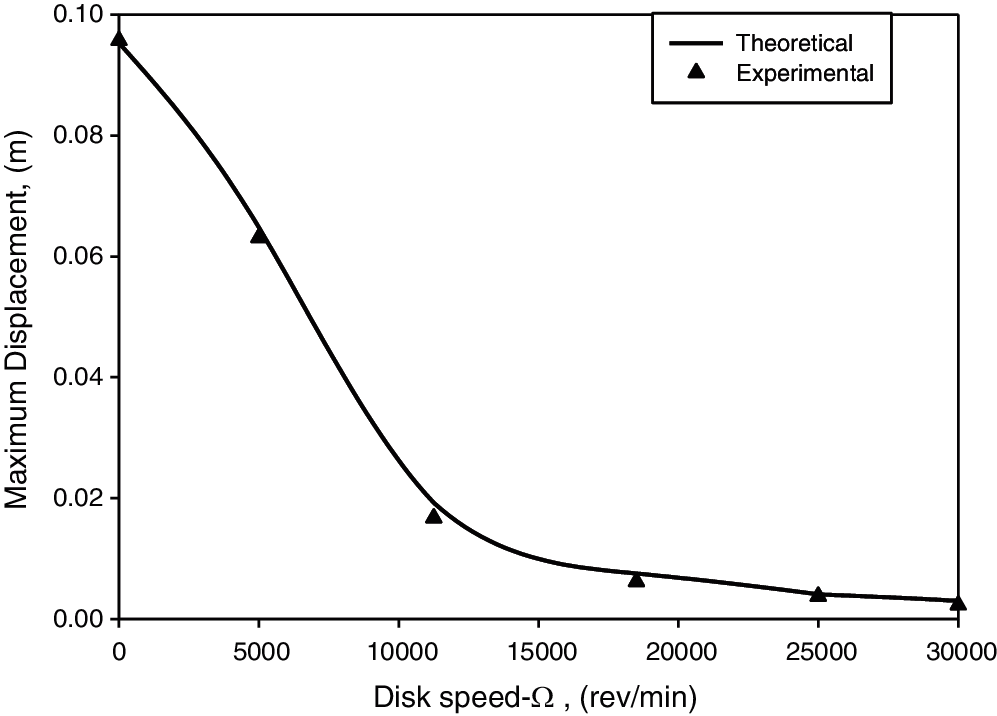
Figure 8: Disk speed vs. beam maximum displacement with parameters of ωn = 4.13 Hz, m = 0.0344 kg and z0 = 1.3 mm
Figs. 7 and 9 represent the frequency response curves of different disk masses (m = 0.0344 kg, 0.0263 kg, respectively) and varying rotational speeds of Ω = 0, 11250, 25000 rpm. Figs. 8 and 10 also represent the frequency response curves of different disk masses at varying rotational speeds (Ω = 0–30000 rpm) of disk masses of m = 0.0344 and 0.0263 kg, respectively. The results indicate that the displacement response is effectively reduced at the first mode of resonant frequency; by increasing the disk mass or disk velocity the vibration in the first mode resonant frequency was reduced, which demonstrates that the vibration attenuation was mainly caused by the angular momentum of the gyroscope.
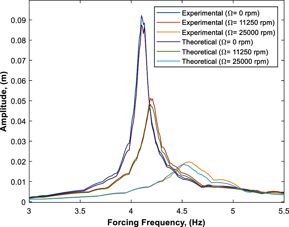
Figure 9: Theoretical and experimental frequency response curves of the beam with parameters of Ω = 0 rpm, 11250 rpm, 25000 rpm, z0 = 1.3 mm, m = 0.0263 kg and ωn = 4.13 Hz
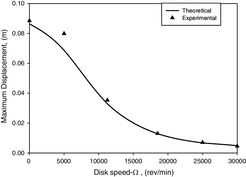
Figure 10: Disk speed vs. beam maximum displacement with parameters of ωn = 4.13 Hz, m = 0.0263 kg and z0 = 1.3 mm
Theoretical and experimental frequency response curves of the beam with gyrostabilizer system were obtained with constant parameters of the system natural frequency (ωn = 4.13 Hz), forcing amplitude (z0 = 1.3 mm) and rotating mass (m = 0.0263 kg) and varying disk speeds of Ω = 0, 11250 and 25000 rpm as seen in Fig. 9. The only difference between Figs. 7 and 9 are the disk mass being 0.0344 kg in Fig. 7 and 0.0263 kg in Fig. 9. The reduction in disk mass showed less effect on reducing the amplitude of the system when compared to the higher disk mass due to the reduced inertia moment of the gyrostabilizer tip-mass.
The gyrostabilizer with lower disk mass also reduced beam amplitude sıgnificantly as seen from Fig. 10, however the amplitude of the beam was not significantly reduced after speeds of 20000 rpm. The only difference between Figs. 8 and 10 are the disk mass being 0.0344 kg in Fig. 8 and 0.0263 kg in Fig. 10. Reducing the disk mass was still effective in reducing the beam amplitude, but it caused an increase in the optimal speed of the disk due to decreasing the inertia moment of the gyrostabilizer as seen in Fig. 10.
4.2 Results for Different Excitation Amplitude
Theoretical and experimental frequency response curves of the beam system with constant parameters of ωn = 4.13 Hz, m = 0.0344 kg and Ω = 11250 rpm were obtained with variable parameters of forcing amplitude z0 = 0.6 mm, 1.3 mm and 2.0 mm as seen in the Fig. 11. Graphical results in show that an increased forcing amplitude also amplified the maximum displacement of the beam amongst other parameters.
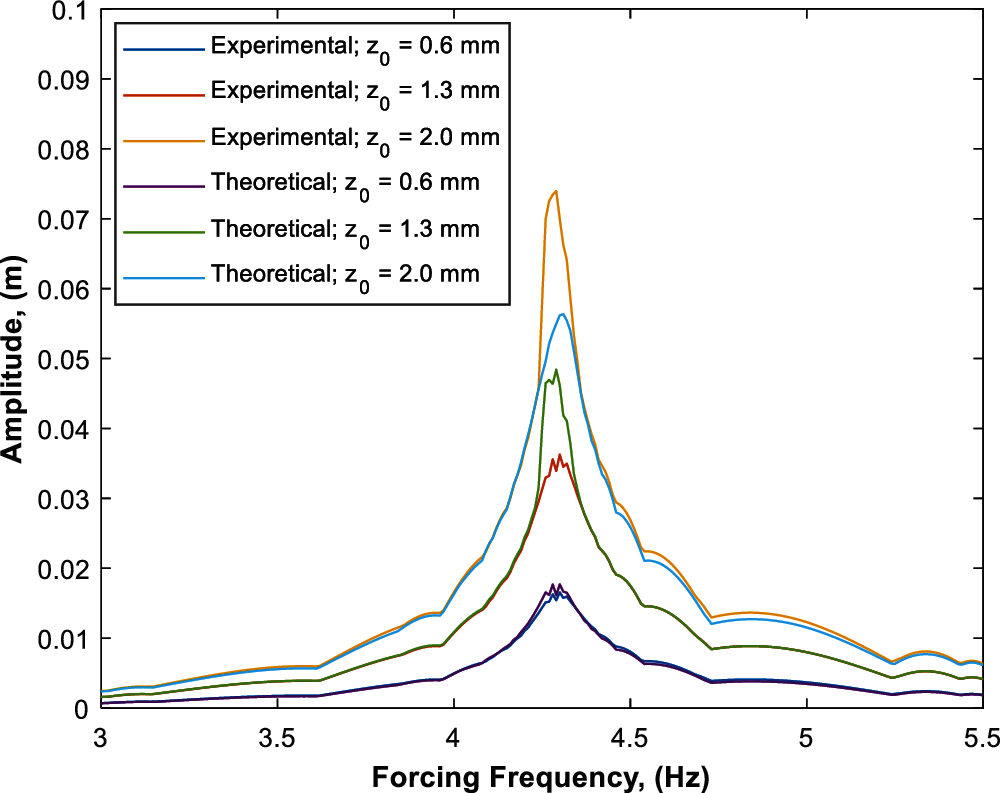
Figure 11: Theoretical and experimental frequency response curves of the beam with different excitation amplitudes (z0) with stable parameters of m = 0.0344 kg and Ω = 11250 rpm
Equations of motion of a cantilever beam with gyrostabilizer tip-mass at one end and harmonic base excitation at the other end have been obtained in this paper. The experimental apparatus was built strictly to specifications listed in Tab. 1 in order to verify theoretical results. All investigations concluded that theoretical and experimental results were in agreement and theoretical results were verified. In which, the following conclusions are found:
• The natural frequency of the beam gyrostabilizer system is significantly increased by disk speed and is fairly effected by the mass of the disk. Higher disk speed of the gyrostabilizer in turn increased the stiffness of the beam caused by the moment of inertia of rotating disk.
• The investigation clearly shows the amplitude of beam at the free end is highly influenced by the disk speed of the gyrostabilizer and is fairly effected by the mass of the disk. Disk speed exponentially reduced the amplitude of the system. However, it is observed that disk speed of the gyrostabilizer becomes minimally effective on amplitude after the disk speed of Ω = 20000 rev/min. The gyro reduces the displacement amplitude of beam nearly by 100% by using the disk speed of Ω = 30000 rev/min.
Funding Statement: The authors received no specific funding for this study.
Conflicts of Interest: The authors declare that they have no conflicts of interest to report regarding the present study.
1. Hu, Q., Jia, Y., Xu, S. (2014). Dynamics and vibration suppression of space structures with control moment gyroscopes. Acta Astronautica, 96, 232–245. DOI 10.1016/j.actaastro.2013.11.032. [Google Scholar] [CrossRef]
2. Kraus, K., Šika, Z., Beneš, P., Krivošej, J., Vyhlídal, T. (2020). Mechatronic robot arm with active vibration absorbers. Journal of Vibration and Control, 26(13–14), 1145–1156. DOI 10.1177/1077546320918488. [Google Scholar] [CrossRef]
3. Keye, S., Keimer, R., Homann, S. (2009). A vibration absorber with variable eigenfrequency for turboprop aircraft. Aerospace Science and Technology, 13(4–5), 165–171. DOI 10.1016/j.ast.2008.10.001. [Google Scholar] [CrossRef]
4. Kuseyri, S. (2020). Constrained H∞ control of gyroscopic ship stabilization systems. Proceedings of the Institution of Mechanical Engineers, Part M: Journal of Engineering for the Maritime Environment, 234(3), 634–641. DOI 10.1177/1475090220903217. [Google Scholar] [CrossRef]
5. MoradiMaryamnegari, H., Khoshnood, A. M. (2019). Robust adaptive vibration control of an underactuated flexible spacecraft. Journal of Vibration and Control, 25(4), 834–850. DOI 10.1177/1077546318802431. [Google Scholar] [CrossRef]
6. Hu, C. (2019). A novel method for vibration mitigation of complex mechanical systems. Sound & Vibration, 53(5), 199–206. DOI 10.32604/sv.2019.07712. [Google Scholar] [CrossRef]
7. Soleymani, M., Norouzi, M. (2021). Active gyroscopic stabilizer to mitigate vibration in a multimegawatt wind turbine. Wind Energy, 24, 720–736. DOI 10.1002/we.2599. [Google Scholar] [CrossRef]
8. Friswell, M. I., Ali, S. F., Bilgen, O., Adhikari, S., Lees, A. W. et al. (2012). Non-linear piezoelectric vibration energy harvesting from a vertical cantilever beam with tip mass. Journal of Intelligent Material Systems and Structures, 23(13), 1505–1521. DOI 10.1177/1045389X12455722. [Google Scholar] [CrossRef]
9. Labuschagne, A., Rensburg, N. F. J., Merwe, A. J. (2009). Comparison of linear beam theories. Mathematical and Computer Modelling, 49(1–2), 20–30. DOI 10.1016/j.mcm.2008.06.006. [Google Scholar] [CrossRef]
10. Hassanpour, S., Heppler, G. R. (2016). Dynamics of 3D timoshenko gyroelastic beams with large attitude changes for the gyros. Acta Astronautica, 118, 33–48. DOI 10.1016/j.actaastro.2015.09.012. [Google Scholar] [CrossRef]
11. Ünker, F., Çuvalcı, O. (2016). Optimum tuning of a gyroscopic vibration absorber using coupled gyroscopes for vibration control of a vertical cantilever beam. Shock and Vibration, 2016, 1–10. DOI 10.1155/2016/1496727. [Google Scholar] [CrossRef]
12. Özer, A., Ghodsi, M., Sekiguchi, A., Saleem, A., Al-Sabari, C. M. N. (2015). Design and experimental implementation of a beam-type twin dynamic vibration absorber for a cantilevered flexible structure carrying an unbalanced rotor: Numerical and experimental observations. Shock and Vibration, 2015, 1–9. DOI 10.1155/2015/154892. [Google Scholar] [CrossRef]
13. Park, B., Lee, Y., Park, M., Ju, Y. K. (2018). Vibration control of a structure by a tuned liquid column damper with embossments. Engineering Structures, 168, 290–299. DOI 10.1016/j.engstruct.2018.04.074. [Google Scholar] [CrossRef]
14. Ünker, F. (2020). Tuned gyro pendulum stabilizer for control of vibrations in structures. International Journal of Acoustics and Vibration, 25(3), 355–362. DOI 10.20855/ijav.2018. [Google Scholar] [CrossRef]
15. Cuvalci, O. (2000). The effect of detuning parameters on the absorption region for a coupled system: A numerical and experimental study. Journal of Sound and Vibration, 229(4), 837–857. DOI 10.1006/jsvi.1999.2526. [Google Scholar] [CrossRef]
16. Ertas, A., Cuvalci, O., Ekwaro-Osire, S. (2000). Performance of pendulum absorber for a nonlinear system of varying orientation. Journal of Sound and Vibration, 229(4), 913–933. DOI 10.1006/jsvi.1999.2521. [Google Scholar] [CrossRef]
17. Soong, T. T., Dargush, G. F. (1997). Passive energy dissipation system in structural engineering. John Wiley & Sons, Ltd., Baffins Lane, Chichester, England. [Google Scholar]
18. Soong, T. T., Spencer, B. F. (2002). Supplemental energy dissipation: State-of-the-art and state-of-the practice. Engineering Structures, 24(3), 243–259. DOI 10.1016/S0141-0296(01)00092-X. [Google Scholar] [CrossRef]
19. Gattringer, H., Müller, A., Jörgl, M. (2019). Mechatronic design of a gyro-stabilized bicycle. In: Aspragathos, N., Koustoumpardis, P., Moulianitis, V. (edsAdvances in service and industrial robotics, vol. 67, pp. 300–307. Mechanisms and Machine Science Springer, Cham, Switzerland. DOI 10.1007/978-3-030-00232-9_31. [Google Scholar] [CrossRef]
20. Zhang, X., Liu, Q., Liu, J., Zhu, Q., Hu, H. (2021). Using gyro stabilizer for active anti-rollover control of articulated wheeled loader vehicles. Proceedings of the Institution of Mechanical Engineers, Part I: Journal of Systems and Control Engineering, 235(2), 237–248. DOI 10.1177/0959651820937114. [Google Scholar] [CrossRef]
21. Palraj, M., Rajamanickam, P. (2020). Motion control of a barge for offshore wind turbine (OWT) using gyrostabilizer. Ocean Engineering, 209, 107500. DOI 10.1016/j.oceaneng.2020.107500. [Google Scholar] [CrossRef]
22. Hu, Q., Jia, Y., Hu, H., Xu, S., Zhang, J. (2016). Dynamics and modal analysis of gyroelastic body with variable speed control moment gyroscopes. Journal of Computational and Nonlinear Dynamics, 11(4), 044506. DOI 10.1115/1.4033438. [Google Scholar] [CrossRef]
23. Ünker, F., Çuvalcı, O. (2016). Experimental investigation of a gyroscopic vibration absorber for vibration control of a vertical cantilever beam. The Fourth International Conference Advances in Civil, Structural and Mechanical, 3(1), 78–82. DOI 10.15224/978-1-63248-093-4-74. [Google Scholar] [CrossRef]
24. Ünker, F., Çuvalcı, O. (2019). Optimum tuning of a gyroscopic vibration absorber for vibration control of a vertical cantilever beam with tip mass. The International Journal of Acoustics and Vibration, 24(2), 210–216. DOI 10.20855/ijav.2019.24.21158. [Google Scholar] [CrossRef]
25. Nayfeh, A., Pai, P. (2004). Linear and nonlinear structural mechanics. John Wiley & Sons Inc., USA. [Google Scholar]
26. Zavodney, L., Nayfeh, H. A. (1989). The nonlinear response of a slender beam carrying a lumped mass to a principal parametric excitation: Theory and experiment. International Journal of Non-Linear Mechanics, 24(2), 105–125. DOI 10.1016/0020-7462(89)90003-6. [Google Scholar] [CrossRef]
27. Esmailzadeh, E., Nakhaie-Jazar, G. (1998). Periodic behavior of a cantilever beam with end mass subjected to harmonic base excitation. International Journal of Non-Linear Mechanics, 33(4), 567–577. DOI 10.1016/S0020-7462(97)00038-3. [Google Scholar] [CrossRef]
 | This work is licensed under a Creative Commons Attribution 4.0 International License, which permits unrestricted use, distribution, and reproduction in any medium, provided the original work is properly cited. |