DOI:10.32604/cmc.2022.021018
| Computers, Materials & Continua DOI:10.32604/cmc.2022.021018 | |
| Article |
Fractional Order Linear Active Disturbance Rejection Control for Linear Flexible Joint System
1Department of Electrical and Computer Engineering (ECE), King Abdulaziz University, Jeddah, 21589, Saudi Arabia
2Center of Excellence in Intelligent Engineering Systems (CEIES), King Abdulaziz University, Jeddah, 21589, Saudi Arabia
3L2CSP Laboratory, Mouloud Mammeri University, Tizi Ouzou, Algeria
4Electrical & Computer Engineering Department, University of Sharjah, United Arab Emirates
5Department of Nuclear Engineering, King Abdulaziz University, Jeddah, 21589, Saudi Arabia
6Department of Mathematics, King Abdulaziz University, Jeddah, 21589, Saudi Arabia
*Corresponding Author: Ibrahim M. Mehedi. Email: imehedi@kau.edu.sa
Received: 19 June 2021; Accepted: 02 August 2021
Abstract: A linear flexible joint system using fractional order linear active disturbance rejection control is studied in this paper. With this control scheme, the performance against disturbances, uncertainties, and attenuation is enhanced. Linear active disturbance rejection control (LADRC) is mainly based on an extended state observer (ESO) technology. A fractional integral (FOI) action is combined with the LADRC technique which proposes a hybrid control scheme like FO-LADRC. Incorporating this FOI action improves the robustness of the standard LADRC. The set-point tracking of the proposed FO-LADRC scheme is designed by Bode's ideal transfer function (BITF) based robust closed-loop concept, an appropriate pole placement method. The effectiveness of the proposed FO-LADRC scheme is illustrated through experimental results on the linear flexible joint system (LFJS). The results show the enhancement of the robustness with disturbance rejection. Furthermore, a comparative analysis is presented with the results obtained using the integer-order LADRC and FO-LADRC scheme.
Keywords: Active disturbance rejection; fractional calculus; ADRC; pole placement; linear flexible joint system; robust control
Due to the increasing complexity of industrial systems, it has become more difficult to analyze and control. Moreover, the non-linear behavior of physical systems produces uncertainties that cause modeling issues of those systems. There are mainly two types of uncertainties, one is internal (unknown parameters or un-modelled dynamics) and the other one is external (disturbances). Therefore, several robust control system design methods are developed for uncertain systems which has followed several directions. Sliding mode is one of those control directions which acts against external disturbances of linear or non-linear systems [1,2]. Linear matrix inequalities methods are applied to interval systems with parameter uncertainties [3,4]. Ultra-local models-based data-driven control which is an online parameter identification method is proposed [5,6]. There is another generalized disturbance control method which is effective against internal and the external disturbances [7,8].
Basing on an extended state observer (ESO), a judicious feedback loop is used to estimate and cancel this generalized disruption. Experimental, as well as simulation results have been stated in several examples (see [9,10] for the examples). An interesting control structure is the linear active disturbance rejection control (LADRC) structure. It can solve both the set point tracking (SPT) problem and the disturbance rejection (DR) in an improved way compared to the standard scheme, particularly when there are variable outward disturbances [11]. The LADRC control structure with an integral action is shown in [11]. This structure is simplified to the fractional-order case by interchanging the integer integration action with a non-integer order one. For this, it is required to propose an appropriate method for calculating the parameters of the acquired fractional-order control law, especially the non-integer order, which in this case, is a challenge. The solution often used in the state-space representation is the pole placement method. But this solution is not obvious in this case because of the non-integer order [12]. One other solution can be simply using the supposed ‘augmented model’ consistent with the fractional-order model [13,14–18]. The non-integer order in this solution is not calculated in agreement with the closed-loop (CL) reference model but chosen instead. Also, it has to be rational. Subsequently, the typical polynomial of the augmented model can be simplified to an integer polynomial by using an appropriate change of variable.
A suitable pole placement then makes calculating the parameters of the control law possible. Then again, in this procedure, two significant points need to be taken into consideration. First, the non-integer order of the control law is not calculated in accordance with the CL reference model. In addition, it has to be rational. Secondly, the degree of the integer order of the distinctive polynomial corresponding to the augmented model is very high. This calls for the designer to select a great number of poles while the fractional order model does not require to that extent [19].
However, there is another solution that involves finding a method that makes it plausible to evaluate both the parameters of the control law and the non-integer order presented by the fractional order integrator based on the preferred CL reference model. This is precisely what is presented in this paper, based on the BITF [19]. In this method, it becomes possible to enforce the iso-damping property to the CL model, which makes the robust control law.
The novel ideas of this paper are:
• A method that makes it possible to impose the iso-damping property in the CL model response. For this, a new reference model using the BITF has been proposed. It is to control systems with a high relative degree using fractional-order controllers and to enforce the planeness of the phase margin.
• The LADRC control system, a control structure linked with a fractional order integral action inserted in the SPT loop, has been proposed [20,21].
• The main theoretical contribution is a new design technique of the SPT controller-based design.
• In order to confirm these theoretical results, numerical simulations have been offered and the robustness of the control structure with respect to the SPT controller gain variations.
• The LADRC control structure which has been proposed in this paper has also been applied on an experimental testbed which consists of a linear flexible joint cart system. We have shown that it is possible to implement this structure without modeling the system. Also, this can be useful to improve the sturdiness of the LADRC control technique compared to the other existing control schemes in the literature.
In the standard formulation of LADRC method for a linear integer order system, controlling the complete model of the system is not needed. This method is based on the relative degree and the gain of the model. The controlled scheme for a second order model is shown by:
where, the input of the system is
The key in the LADRC method is estimating the unknown
where:
and
The structure of the full ESO is given by
where, L is the gain vector of the observer.
The parameters
If the estimated error is ignored
As a standard form, set-point tracking is solved by state feedback. So, the control law
where
Fig. 1 represents the standard LADRC structure. This has two gain vectors to design: for the controller, the gain Ko and for the ESO, the gain L. In order to do this, the method usually used is proposed in. This comes down to two parameters:
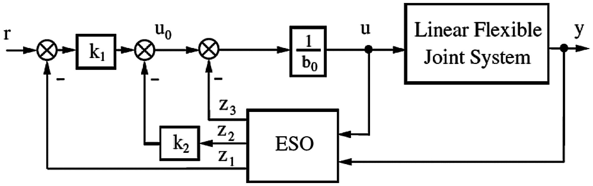
Figure 1: Standard structure of LADRC
3 LADRC with Fractional Order Integral Action
Non-integer order derivatives have several definitions, and these are usually not equivalent to integer-order derivatives [22–25]. A control system linking a LADRC with an integer order integral action has been proposed in [11,20]. Here, a different technique with a fractional integral action has been bought together. It is for improving the performance of the standard LADRC for ambiguous systems, mainly regarding external disturbances. The proposed technique has been shown in Fig. 2.

Figure 2: Control structure of LADRC with fractional integral action
The n poles of the CL characteristic polynomial are allowed to be placed arbitrarily by the state feedback
where
In what follows, the method to design the coefficient of the state feedback
to which it corresponds in open loop
which has the same frequency characteristic as Bode's ideal transfer function when
The closed-loop system with control plant given by Eq. (6) and the control law given by Eq. (8) is
which can be written as
For this transfer function to be equal to the reference model in Eq. (9) it is required that
Remark: To link with the standard LADRC, the set-point tracking controller parameter design
4 Implementation on a Linear Flexible Joint System
The linear flexible joint system, which is a system of two carts sliding on a track, with one of the carts driven by a DC motor, is an interesting example that illustrates the LADRC control scheme and validates the performance of the proposed FO-LADRC. Modeling of this system is fairly complex since two systems interact. Indeed, the cart's motion affects the flexible spring movement and vice-versa. During the testing process, the goal was to determine the position of the cart, and the flexible spring was viewed as a permanent disturbance. A Linear-flexible-joint cart system (LFJ) is shown in Fig. 3. It can be modeled as a two mass-spring system as illustrated in the schematic diagram in Fig. 4 where
To evaluate and compare the performance of the two LADRC structures, the design parameters of the observer are:

Figure 3: Linear flexible joint cart system

Figure 4: Schematic of LFJC

Figure 5: Experimental setup for linear flexible joint cart system
Fig. 6 illustrates the experimental results of the cart position with respect to the reference signal for both FO-LADRC and standard LADRC. The evaluation of the control signal is shown in Fig. 7. Note that the control signal is more important for the FO-LADRC structure. It is observed to have a little faster transient response by the FO-LADRC scheme. This result was to be expected as the FO scheme becomes nervous at startup and it shows slow performance in steady-state responses.

Figure 6: CL behavior of linear cart position for FO-LADRC and standard LADRC (blue line: with the FO-LADRC, black line: standard LADRC)

Figure 7: The evolution of the control signal for FO-LADRC scheme
A comparison of the FO-LADRC structures is also made by studying their robustness with respect to the parameter
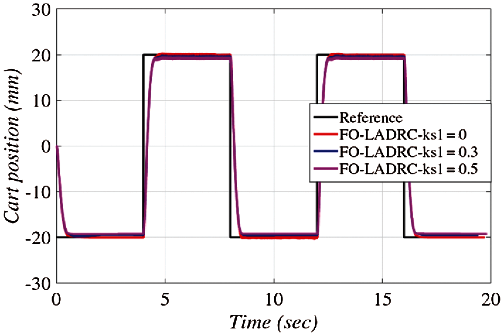
Figure 8: Robustness of linear cart position for FO-LADRC with respect to varying feedback
Fig. 9 illustrates the experimental results of a flexible joint cart position with respect to the reference signal for both FO-LADRC and standard LADRC. The tracking performance of the cart is very r with no overshoot for FO-LADRC scheme.

Figure 9: CL behavior of flexible joint cart position for FO-LADRC and standard LADRC (blue line: with the FO-LADRC, black line: standard LADRC)
Similar to the cart position, a comparison of the FO-LADRC structures is also made for a flexible joint cart position by studying their robustness with respect to the parameter

Figure 10: Robustness of flexible joint cart position for FO-LADRC with respect to varying feedback
This paper, LADRC structure with a fractional order integral action (FO-LADRC) is proposed to control a minimum phase-stable system. Two main contributions are achieved. From the theoretical point of view, based on the BITF, a novel design method of the SPT controller is proposed for the FO-LADRC scheme. From a practical point of view, the use of LADRC control scheme is an important contribution since no modeling of the system was needed and all the parameters of the system are not accessible. Nevertheless, minimal knowledge of the system is necessary. We knew for example, that the relative degree of the model of the DC motor position is equal to 2. That is why a third order ESO is used to estimate the generalized disturbance. Through experiments on the linear flexible joint system (LFJS), the FO-LADRC scheme is shown to be effective. With disturbance rejection, the robustness of the system is enhanced. Additionally, this paper presents a comparison of results obtained by the integer-order LADRC and FO-LADRC schemes.
Acknowledgement: This research work was funded by Institutional Fund Projects under Grant No. (IFPRC-027-135-2020). Therefore, authors gratefully acknowledge technical and financial support from the Ministry of Education and King Abdulaziz University, Jeddah, Saudi Arabia.
Funding Statement: This research work was funded by Institutional Fund Projects under Grant No. (IFPRC-027-135-2020).
Conflicts of Interest: The authors declare that they have no conflicts of interest to report regarding the present study.
 | This work is licensed under a Creative Commons Attribution 4.0 International License, which permits unrestricted use, distribution, and reproduction in any medium, provided the original work is properly cited. |