DOI:10.32604/iasc.2022.019083
| Intelligent Automation & Soft Computing DOI:10.32604/iasc.2022.019083 | |
| Article |
Development of A Low-Cost Exoskeleton for Rehabilitation and Mobility
1Department of Electrical and Computer Engineering, North South University, Bashundhara, Dhaka-1229, Bangladesh
2Department of Computer Science, College of Computers and Information Technology, Taif University, P. O. Box 11099, Taif, 21944, Saudi Arabia
*Corresponding Author: Mohammad Monirujjaman Khan. Email: monirujjaman.khan@northsouth.edu; monirkhan.qmul@gmail.com
Received: 01 April 2021; Accepted: 02 May 2021
Abstract: Paralysis is detrimental to people in catastrophic ways: losing income opportunities, becoming a burden to their friends and family, further physical deterioration, and the combination of these occurrences can often lead to depression. In third world countries, suffering from paralysis can be extra deleterious, where a large proportion of the population is engaged in some form of physical labor. The number of people exposed to paralysis risk factors is also increasing, with more and more people having hypertension, smoking, and other abnormalities. Besides, low workplace safety precautions may lead to an increased risk of spinal cord injury in developing nations. However, very few solutions have been developed to aid people in third-world countries suffering from paralysis. In this paper, a low-cost upper arm exoskeleton design has been presented that can be controlled biometrically and can also be used as an analytical tool. Two additional input options are added to the system to reduce the cost and its calibration. The system has been tested in a lab environment to assure the accuracy of actuation and measurement. Some of the limitations of the current prototype and the prospect for its further enhancement have been highlighted.
Keywords: Low cost; exoskeleton; application design; computer vision; Human-Computer Interaction (HCI); inverse kinematics; microcontroller; robotics
Paralysis is a condition defining the loss of control or strength in a muscle or group of muscles. This condition develops due to miscommunication between the nervous system and the muscles in question as the muscles no longer respond to the nerve impulses sent to them. This condition can develop due to numerous occurrences noted in Armour et al. [1], which include: stroke, spinal cord injury, brain injury, and other illnesses such as cerebral palsy, multiple sclerosis, etc. Global statistics on stroke and its impact around the world are documented in Kim et al. [2].
Someone afflicted with partial or complete paralysis of a limb or group of limbs must face further issues alongside this condition. The patient will often lose economic opportunities since they cannot perform physical labor such as picking up heavy objects, operating machinery, or even writing. As a knock-on effect of this, sufferers can become a burden upon their friends and family as they cannot provide for themselves financially. In some cases, the paralyzed may also be unable to go about their day-to-day activities without doing mundane tasks such as feeding themselves with a spoon or brushing their teeth. Paralysis can also have secondary detrimental physical effects such as the increased risk of developing blood clots, restricted blood flow, and pain. All of the problems mentioned above can lead to sorrow within sufferers that can manifest itself as depression, leading them to lash out, harm themselves or others, and even commit suicide.
All the factors mentioned above contribute to the need for appropriate measures to combat the effects of paralysis. Traditionally, a diverse set of tools and professionals is required to accomplish this. The sufferers had to attend physical therapy sessions to receive treatment from a trained professional. Occupational therapy must be generated to deal with day-to-day activities, and regular equipment tools and services must be significantly modified to allow them to function daily. The traditional methods of paralysis treatment have many limitations, which make them unappealing. Firstly, the treatment requires a patient’s dedication in terms of time and is financially expensive. The sufferer has to spend extended periods in rehabilitation, due to which they cannot pursue professional activities. Secondly, the current methods require the adaptation of the environment to the paralyzed person’s needs, which inflicts costs upon the places they go to, work at, and live. Moreover, rehabilitation can often be a long and arduous journey that can be heavily taxing both physically and emotionally. Therefore, this highlights the need for a superior methodology to treat and manage paralysis. To accomplish this, researchers have proposed numerous technologies, which include the use of electrical stimulus [3], cloud-based systems [4], robot-assisted rehabilitation [5], virtual reality [6], and many others.
However, despite the numerous traditional and experimental developments for paralysis handling and treatment, they may be unfeasible for many people who have such paralysis. Especially in a low-income third-world country like Bangladesh, a high level of treatment and care is not possible due to most citizens’ economic constraints and an overall lack of resources. To highlight this fact, currently, there is only one entity in Bangladesh actively working on the topic of paralysis: The Centre for Rehabilitation of the Paralyzed (CRP). Moreover, the CRP treatment is very traditional and palliative in nature, making their solutions not perfectly adapted for use in Bangladesh. Due to the lack of resources, risk factors for paralysis are rising in Bangladesh. The primary cause of paralysis is stroke, and the risk factors for stroke are on the rise in Bangladesh, as highlighted in Islam et al. [7–9]. Furthermore, external risk factors for paralysis, such as spinal cord and head injury, are also prevalent in Bangladesh due to poor road and workplace safety standards at a national and governmental level.
The prevalence of risk factors for paralysis in Bangladesh and the lack of resources dedicated to alleviating the problem require embracing a new solution adapted to Bangladeshi people’s treatment and their unique conditions. Firstly, the solution that needs to be put forward should be able to improve current techniques. So, this solution must be singular such that the costs and responsibilities of handling the condition are not passed onto the sufferer’s friends, family, and acquaintances. It should also allow people to use the technique independently while doing mundane tasks by themselves. Moreover, the solution must provide a system that will enable the user to grasp their rehabilitation rate to avoid hopelessness that often manifests during the rehabilitation period. Finally, the solution must also be adapted to Bangladesh’s unique situation where per capita income is less than $2000 per year. A large portion of the population is engaged in physical labor.
In this paper, we put forward the design and implementation of a powered exoskeleton system to handle paralysis problems and the shortcomings of traditional treatment methods. A powered exoskeleton is a mechanical system that can be mounted onto the body where the system’s joints are moved by actuators such as a motor, linear actuator, etc. Several articles in the literature have already presented the concept of exoskeleton use for arm rehabilitation [10–12], and there are even commercial solutions available for purchase. However, none of these systems can gracefully be adapted to the unique challenges of Bangladesh.
An exoskeleton system intended for upper arm rehabilitation has been designed and constructed. The system mounts onto the paralyzed arm and actuates the elbow hinge using a servo motor. It is controlled biometrically using electromyographic (EMG) readings from the bicep. The noise and person-to-person variability of electromyographic signals necessitate designing a secondary input option that we added in the form of joystick control and an Android application. Besides, we have developed an application using MATLAB for monitoring rehabilitation by analyzing EMG signals detected from the bicep. The system is then tested in a lab environment to measure the accuracy of the analysis tool and the arm’s ability to trace according to the EMG signal detected in the arm. A comparative analysis has been performed between our solution and previously designed systems to highlight our system’s success concerning the critical design aspects. Finally, we highlight our system’s limitations and then suggest improvements that can be made to the system for future research and real-world adoption. The proposed system contributes significantly to the current work in this area since it can perform multiple functions by acting both as a tool to help in day-to-day activity and performance analyzer. Previous work in this area usually focused on either of the two aspects mentioned above while being significantly more expensive than our solution.
We organize the rest of the article as follows. In Section two method and methodology have been provided. Results and analysis have been presented in Section three. Finally Section four describes the conclusion of the paper.
This section presents our proposed exoskeleton arm’s design and development, consisting of a servo motor placed on top of the elbow to actuate the arm. The motor is controlled using a microcontroller. We add three input options to the system: the design and working mechanisms of all three input options are described in detail in this section. We also present the system’s mechanical design and the mathematical extraction of data points using the MATLAB analysis tool.
The block diagram showcasing the design of the entire system is shown in Fig. 1. The system has three input options: phone control, EMG control, joystick control. It is equipped with multiple input options for a few reasons. The most seamless and intuitive control mechanism for an exoskeletal system is biometric. However, biometric input methods have several limitations that make them unsuitable for a device designed to cater to a low-income populace’s needs. Biometric methods such as electrocardiography, although more effective, come with a significant capital expense. Furthermore, there is a high person-to-person variability for such signals. Also, there is an added caveat of noise to the system that can make the tracking of the arm inaccurate nullifying the benefits. So, we add a secondary input method in the form of a joystick controller, which can be controlled by the user using the same arm. Finally, we also create an Android application that can control the device and further control switching between inputs and the analysis tool. The phone controller connects over Bluetooth for cost-savings.
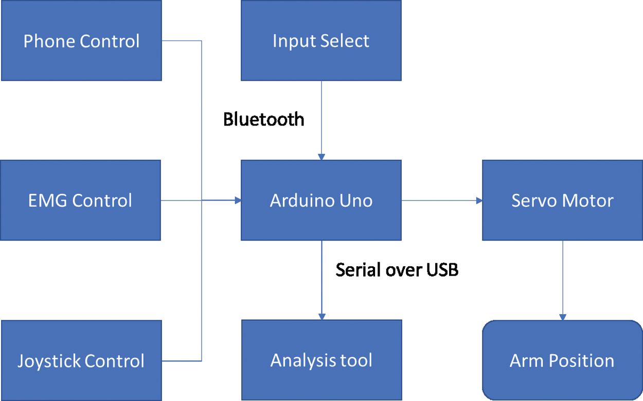
Figure 1: Block diagram of the entire system
The complete circuit diagram for the system is shown in Fig. 2. The system consists of an Arduino Uno R3 microcontroller, an EMG sensor, a joystick module, a servo motor, and an HC-05 Bluetooth module. The EMG sensor and joystick module are connected to the analog pins of the Uno. The servo motor and Bluetooth Module are connected to the digital pins of the microcontroller. The microcontroller and motor are powered by two 3.7 V batteries connected in series. The remaining components are connected to the 5 V power supply on the Arduino board. We elaborate on various input methods of the system in the following subsections.
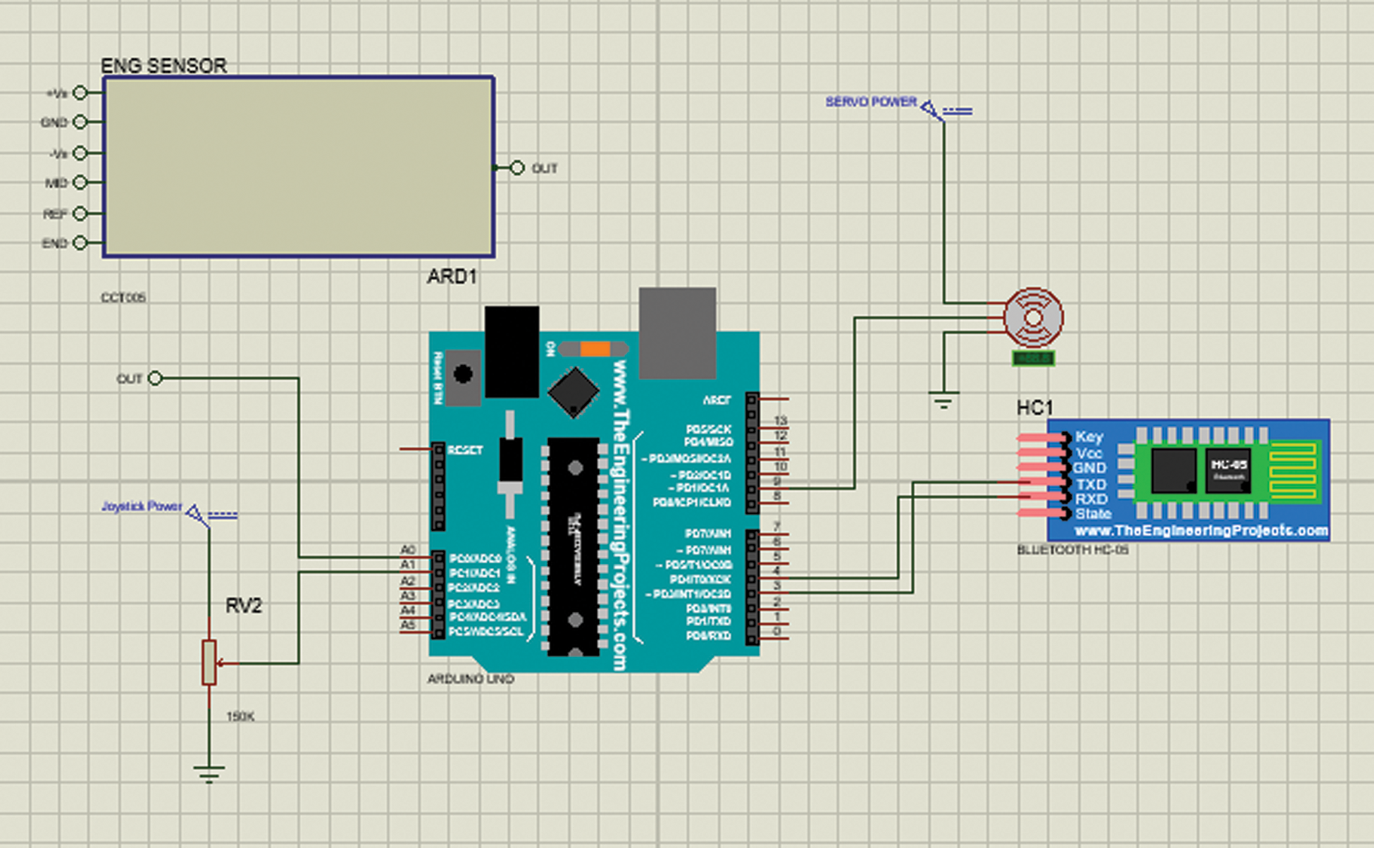
Figure 2: Circuit diagram
A surface electromyography sensor for the biometric input has been used. We decide to use this method instead of other methods such as under surface EMG, where electrodes are placed directly under the skin, or EEG. Here many electrodes are placed on top of the head. These alternative methods offer greater accuracy than EMG. However, they are significantly more expensive and invasive, making them contrary to our goal of creating an affordable system that can be used daily. The sensor circuit is illustrated in Fig. 3.
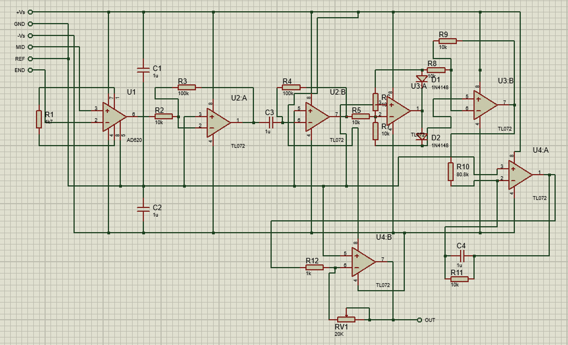
Figure 3: EMG sensor circuit
The working principle for the EMG sensing circuit is shown in Fig. 4. First, the sensor acquires the EMG signal and then amplifies the signal. The alternating current signal is then rectified and filtered to generate a root mean squared value for the signal. The analog signal is then converted to a digital signal using the following formulation:
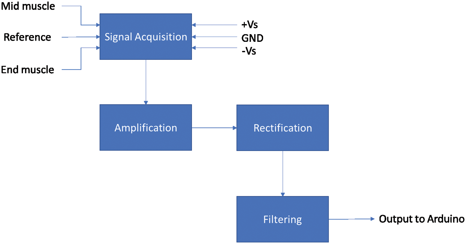
Figure 4: EMG sensor block diagram
The microcontroller does the analog to digital conversion. The work accomplished by the operational amplifiers is shown in Fig. 4. Signal acquisition is performed via an AD620 instrumentation amplifier, which amplifies the difference between the mid and end muscle reading compared to the reference voltage. This gain for AD620 is 10. Then, the signal is passed through two inverting amplifiers to amplify the signal by 100. Two operational amplifiers form a precision full-wave rectifier that converts the alternating current signal to a direct current signal. The signal then passes through an active low pass filter that cuts unwanted noise from the system and amplifies the desired signal to have a smoothing effect. Finally, the signal terminates at the final op-amp that is configured as an inverting amplifier. The feedback is then provided via a variable resistor so that the signal’s amplification can be controlled. All of the op-amps used in this system, apart from the first one, are TL072 op-amps.
We add the joystick control to the system as an alternative for the user to control the system if the EMG sensor malfunctions or proves to be inaccurate. A joystick module is essentially two variable resistors placed perpendicularly to one another. As our system only controls a single degree of freedom, we will only be using one of the resistors. The mathematical calculation for the system’s output value is performed like the EMG sensor.
The control application is designed to control the device and is connected to the exoskeleton over Bluetooth. It must be used to choose the mode of operation for the device from the following options:
• EMG signal control: the amplitude of the EMG signal actuates the system.
• Joystick control: the position of the joystick sets the rotational position of the servo motor.
• Phone Control: the rotational direction and speed of the device are controlled by the phone.
• Analysis mode: the device is connected to a Personal Computer (PC), and the analysis application is used to measure the EMG signal and extract features of the signal.
In phone control mode, the user can control the exoskeleton’s rotation and speed directly from their phone. Comprehensive functionalities of the control application are shown in Fig. 5. When the application starts up, we enter into the device selection activity phase. Once a device is selected, we enter into the control activity phase. At this point, we can choose between the modes of the device. The relevant command is then sent to the microcontroller on the exoskeleton. If phone control mode is selected, the user can control the arm’s speed and position from the phone itself.
Flowchart for the analysis tool is provided in Fig. 6. A medical expert uses the analysis application to investigate the results and give an informed medical evaluation. The application will display the real-time EMG value while running, and upon completion, the features extracted from the data plot are displayed, giving valuable information to a medical professional. The input for the application is received over serial communication via the Universal Serial Bus (USB) port connected to the exoskeleton.
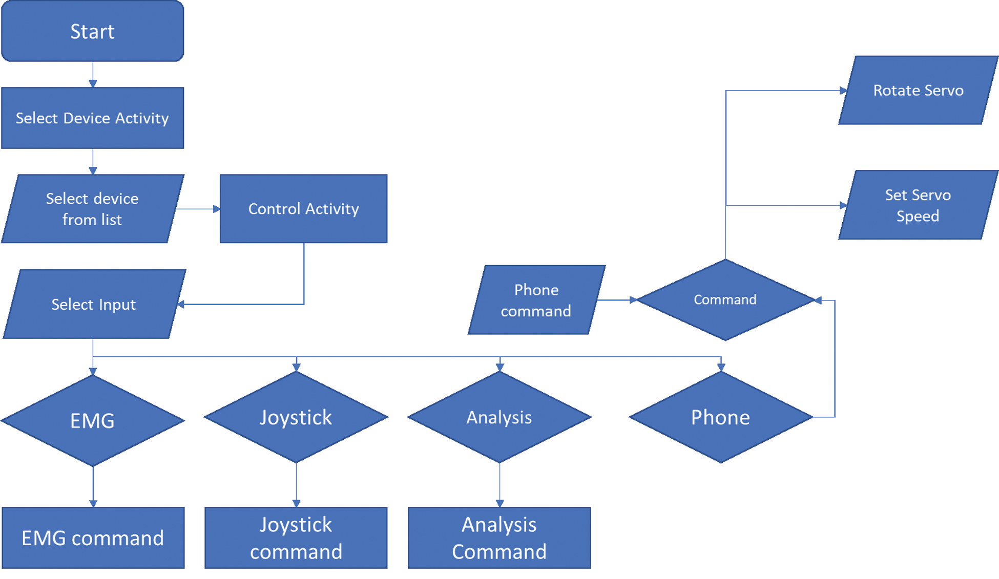
Figure 5: Functionality of control application
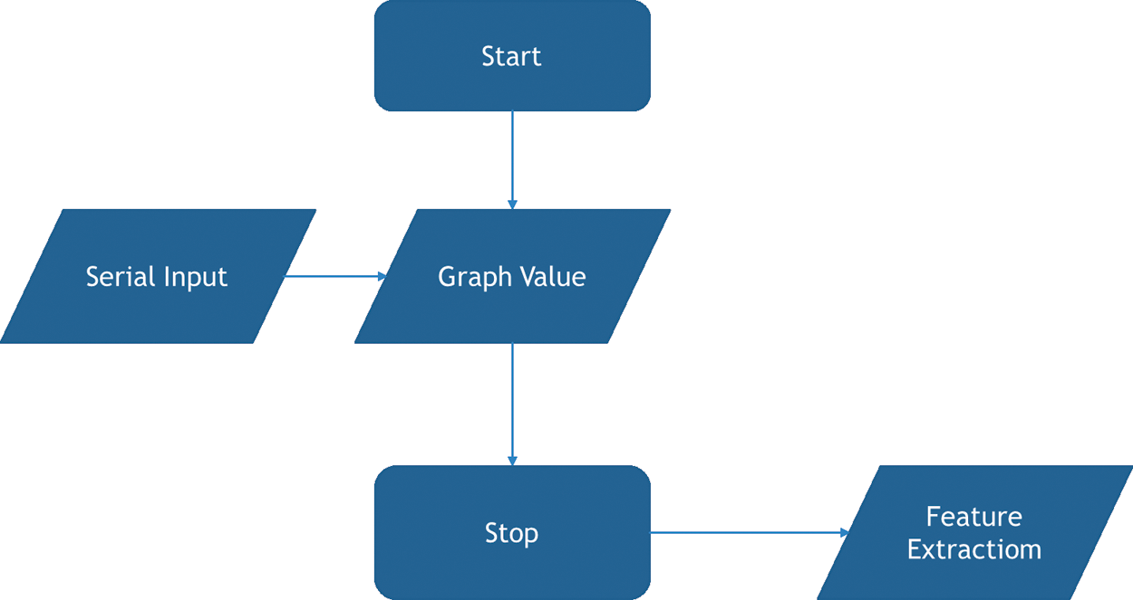
Figure 6: Flowchart for analysis tool
The code flowchart for the application is shown in Fig. 7. Firmware refers to the code that is permanently written onto the device. Upon startup, the device will wait for a command that comes over Bluetooth from the control device. The controller’s command will enter a switch case where the device’s input will be selected based on the command. The function of each control scheme is now explained below:
• EMG control: In this model, the RMS EMG voltage is taken directly from the EMG sensor’s output. The analog input is converted to digital values by the Arduino, which are between 0 and 1023. These numbers are mapped directly onto the servo rotation range of 0 to 170 degrees. Thus, servo rotation becomes proportional to the EMG signal amplitude.
• Joystick Control: In joystick control mode, the output of the device is controlled by the joystick. In the neutral position of the joystick, the servo does not rotate. When the joystick is pushed up, the joystick value becomes more significant than the neutral value, and the servo incrementally rotates to a greater degree. This process is reversed when the joystick is pulled back towards the user.
• Phone control: In this mode, the device waits for commands from the phone. The phone can control both the speed and rotation of device.
Upon completion of any mode, the device loops back to the selection stage, and if the command is changed, we move to another mode, or else we stay in the same mode.
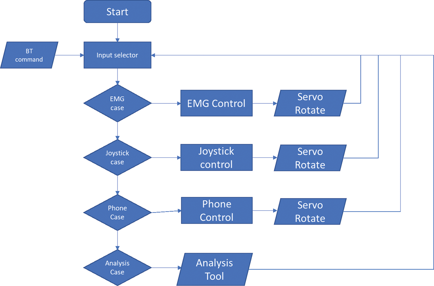
Figure 7: Firmware code flowchart
This section presents the system implementation, including the software interface for the control and analysis application and mechanical arm. A detailed analysis of the experimental results also have been provided. Finally, a performance comparison of our system with other existing works has been presented to establish the fact that this proposed system conforms to the requirements of the niche we sought to fulfill. That is to deliver a system catered to the Bangladeshi paralysis patient.
3.1 Control Application Implementation
The control application designed for this system is shown in Fig. 8. The application interface consists of only two pages: the connectivity page and the controller page. The connectivity page allows users to connect to the arm via Bluetooth by selecting from a list of available devices. The application’s control side enables users to connect or disconnect from the exoskeleton and switch between modes. The application also controls the speed and position of the arm when in phone control mode. The application’s switching capability allows users to control the device with their un paralyzed hand and has the added benefit of moving fine controls to the device rather than adding them to the physical system.
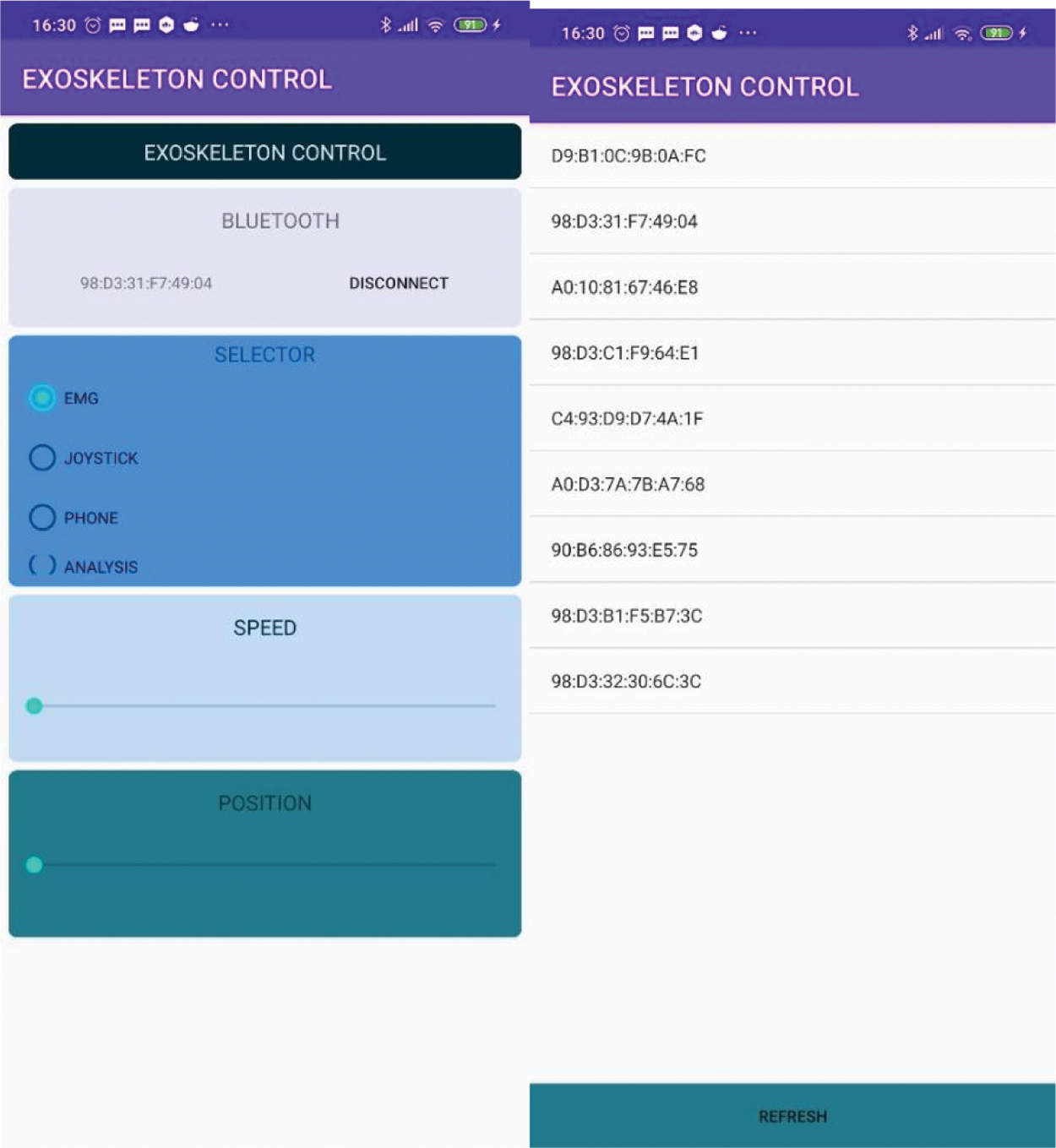
Figure 8: Control Application
3.2 Analytical Application Implementation
Fig. 9 demonstrates the control analytical application, which consists of a graphing area that shows the signal that is being fed by the EMG sensor. The application has two buttons, namely, ‘start’ and ‘stop.’ Below the graph, there are 18 total labels that display relevant data points for the system. When the start button is pressed, the application begins mapping the EMG signal. Upon pressing the stop button, the following features of the signal are extracted:
• Mean Absolute Value (MAV): average distance between the signal’s mean and the points on the graph.
• Enhanced Mean Absolute Value (EMAV): mean absolute value where the value is raised to the power of 0.75 for the inter quartile range or else the power of half.
• Enhanced Wavelength (EWL): value for wavelength is enhanced similar to how it is enhanced for mean absolute value to get EMAV.
• Slope Sign Change (SSC): a measure of the number of times the signal gradient goes from positive to negative or otherwise.
• Zero-Crossing (ZC): a measure of the number of times the EMG value is zero.
• Waveform Length (WL): distance between two mirrored points on a graph.
• Root Mean Square (RMS): the RMS value for the signal is calculated by the square root of the signal’s mean.
• Average Amplitude Change (AAC): average value of the amplitude of the signal during the wave-cycle.
• Difference Absolute Standard Deviation Value (DASDV):
• Log Detector (LD): base 10 absolute value of the ratio between the absolute value of amplitudes of the signal by total time.
• Modified Mean Absolute Value (MMAV)
• Modified Mean Absolute Value 2 (MMAV2)
• Myopulse Percentage Rate (MYOP): ratio of signal greater than the threshold value set by the user.
• Simple Square Integral (SSI): integral of the square of the signal for all values
• Variance of EMG (VAR): the expectation of a random variable’s squared deviation from its mean.
• Willison Amplitude (WA): a measure of the number of instances where the signal’s amplitude increases by a value greater than the threshold value.
• Maximum Fractal Length (MFL)
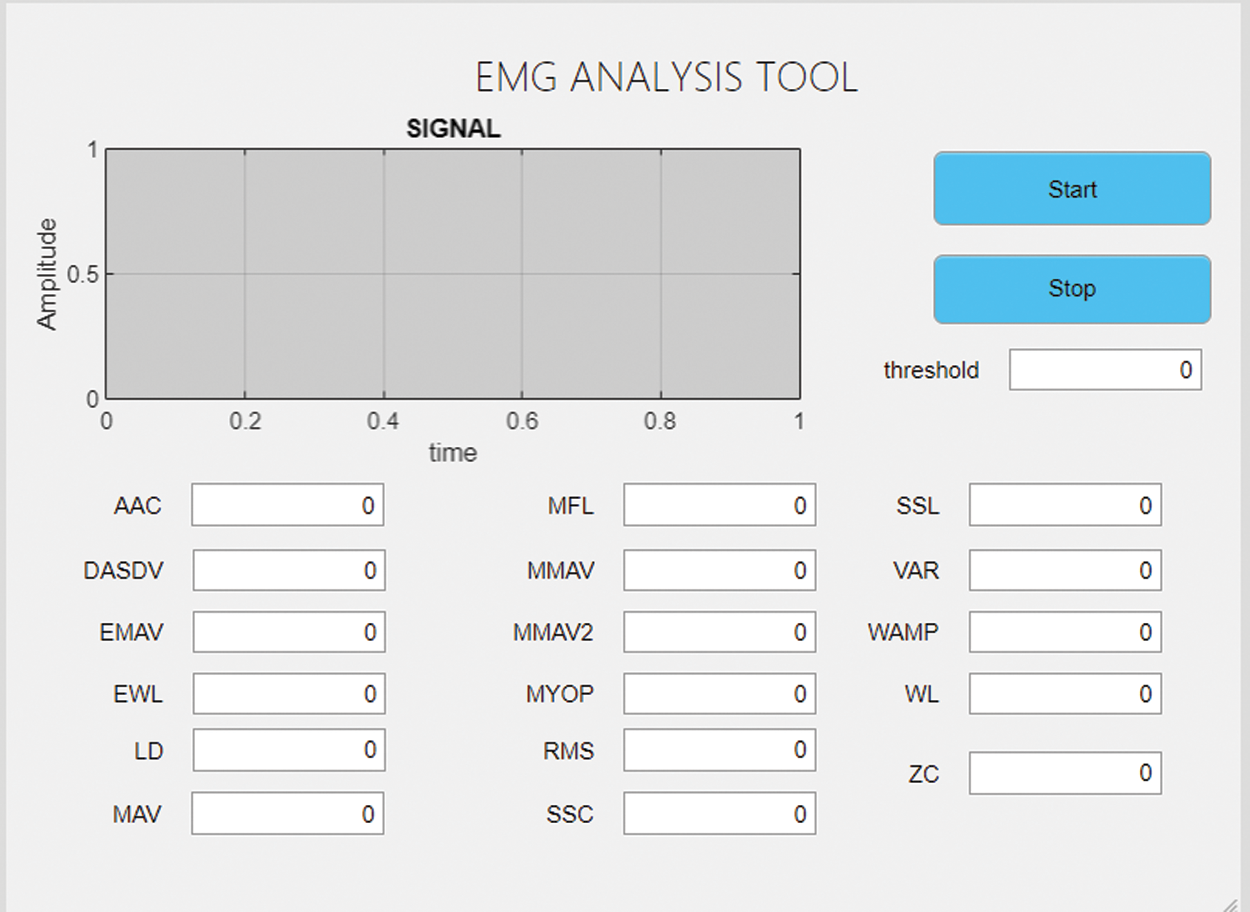
Figure 9: Analytical application
The mechanical implementation of the system is shown in Fig. 10(a). The system can be seen mounted onto the body of the wearer. Two Velcro straps are placed above and below the arm. The circuit implementation is moved to the waist to remove the weight from the user’s already paralyzed arm to minimize the load, which could cause pain and further risks. The circuit is mounted onto the back of the wearer, as shown in Fig. 10(b). Finally, electrodes are placed on the bicep and the elbow, as illustrated in Figs. 10(c) and 10(d), respectively.
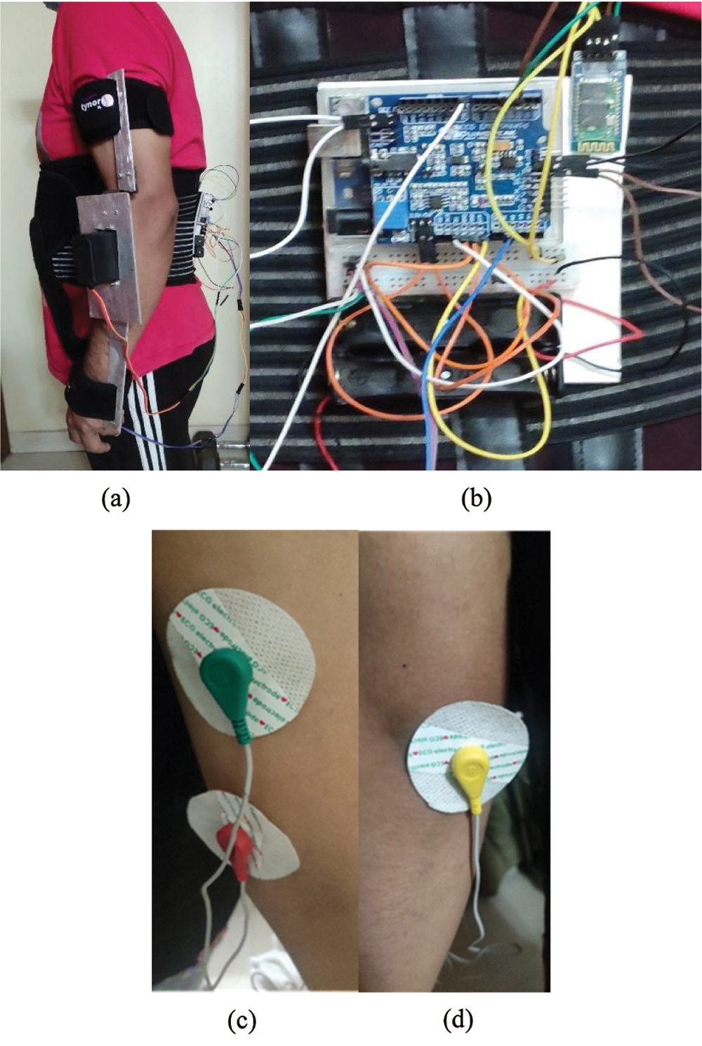
Figure 10: (a) View of mechanical arm mounting; (b) Circuit mounted onto the back; (c) electrode positioned on the bicep; (d) electrode placed on the elbow for reference
3.4 Analysis of Results and Testing
After the construction and coding of the entire system, we tested the system to determine its success. The system is designed to be used by Bangladeshi sufferers of paralysis. So, the cost of the system must be within the budget of the users. The prices for various components are shown in Tab. 1.
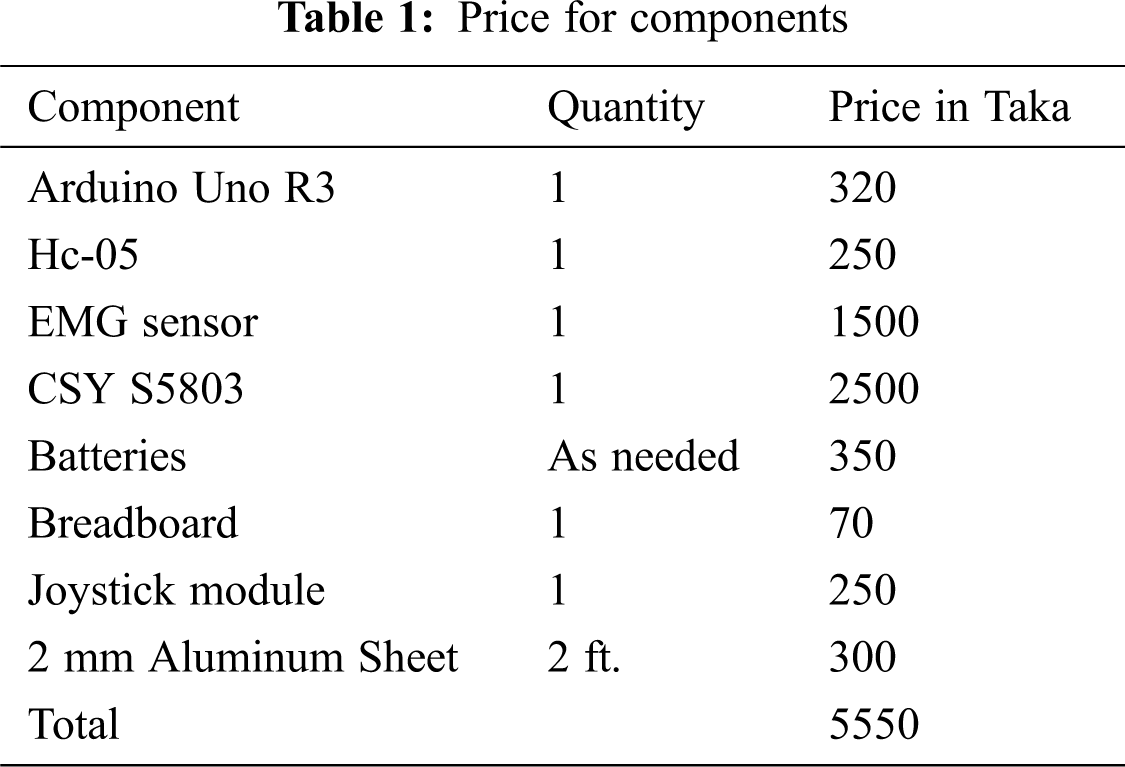
The cost for building the whole system comes out to Bangladeshi Taka 5500, which is equivalent to approximately 70 USD. The system is affordable for the average Bangladeshi citizen even when labor cost is considered.
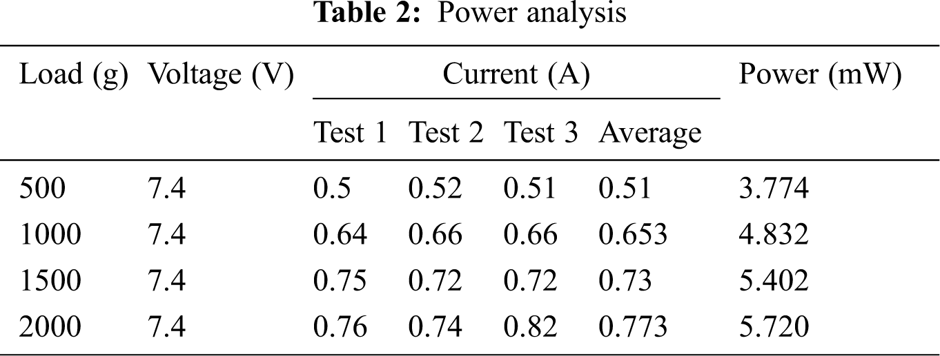
Secondly, the battery life of the system has been considered. So, we need to calculate the system’s load-power characteristics as the system’s final output is the torque applied by the arm. The characteristics are computed by fully actuating the arm with various load configurations, as shown in Tab. 2. The exoskeleton was attached to an arm and controlled using a joystick. The wearer of the exoskeleton did not apply any force while the experiment was being carried out. We observed that power consumption increases with the load, but we could not find such a trend for the current consumption.
Next, the system’s operability testing has been performed thoroughly using each of the input options. To do that, we needed to actuate the system using each input option. We carried out the test as follows:
• An input option was selected using the Android application.
• The arm was actuated 90 degrees.
• This was repeated three times for 90 degrees.
• The above two steps were repeated for 90, 120, 150 degrees.
• If the arm can be successfully actuated with a maximum error of 5 degrees, the corresponding attempt is considered a success, or else it is marked a failure.
Test results are shown in Tab. 3. It has been observed that the system is controllable using all three of the input methods. We did not notice any unsuccessful cases. This proves that the system can be used with any of the input options. A successful testing event is depicted in Fig. 11.
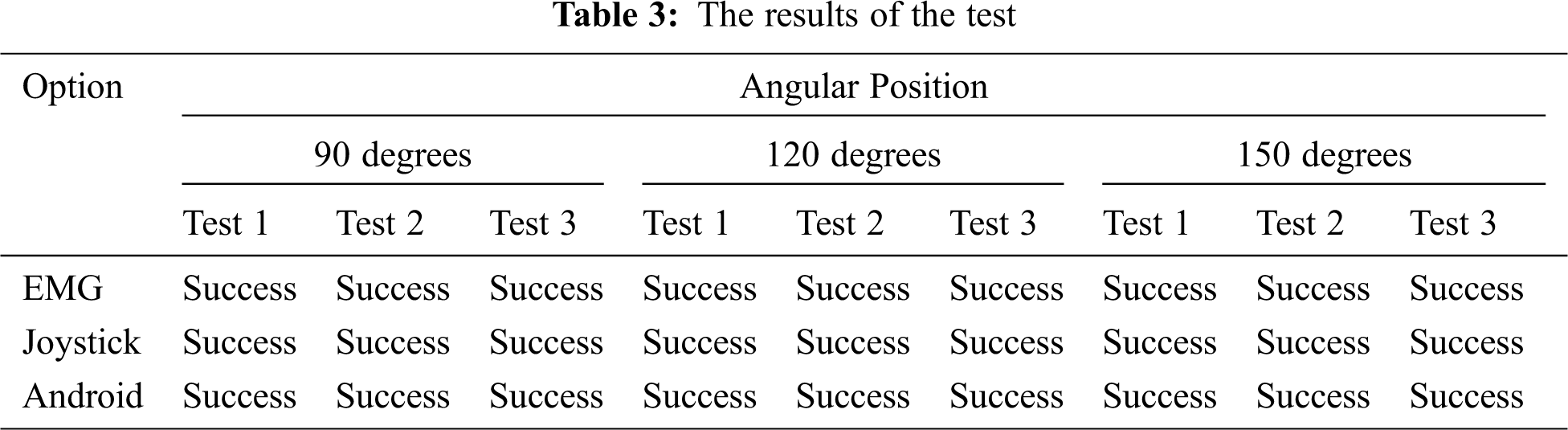
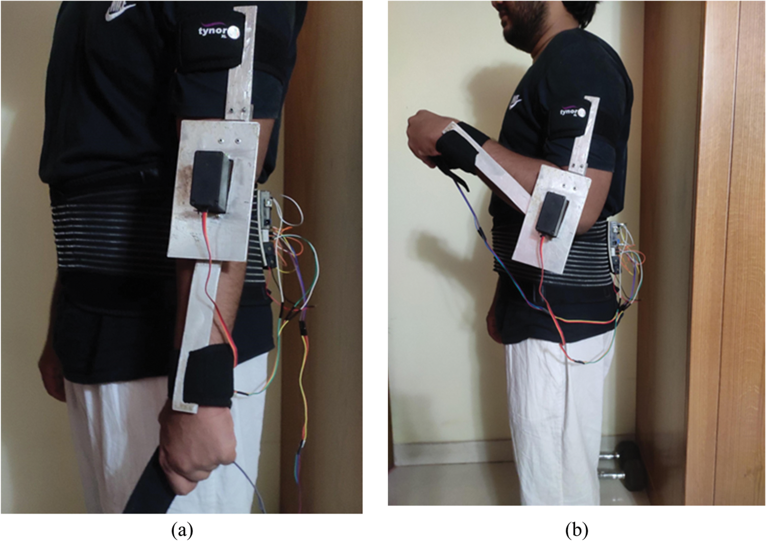
Figure 11: (a) Arm in resting position as the initial position of the test; (b) Arm position at 90 degrees
Finally, to demonstrate this system’s novelty and effectiveness, method of this system has been compared with several previous works done in the field. The comparison is shown in Tab. 4. The systems were compared based on our system’s primary design considerations, including the system’s usability for analytical purposes, rehabilitative purposes, cost-effectiveness, range of motion, degree of freedom, and portability.
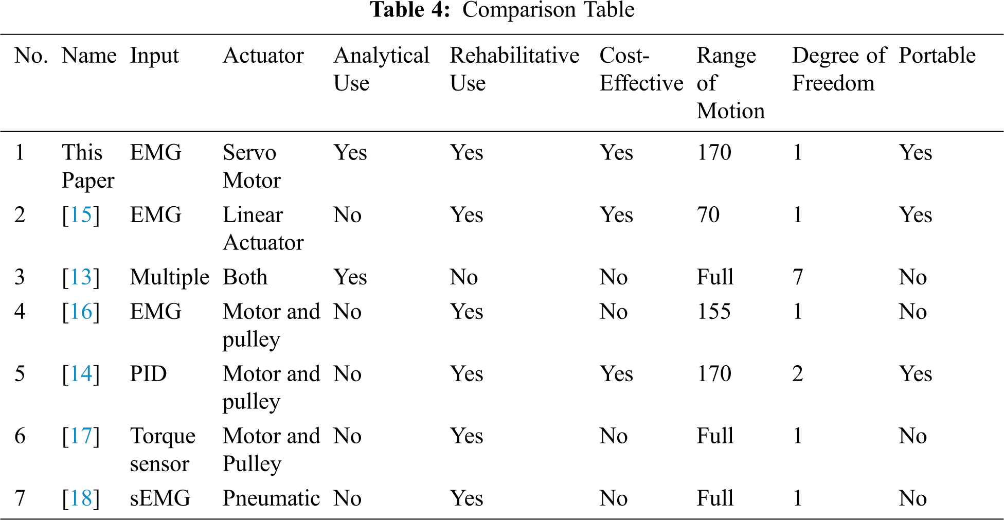
The proposed study constructed an arm with a singular degree of freedom as it can actuate a single joint. Most of the other systems that have been compared also had singular degrees of freedom except for [13] and [14], which had two and seven degrees, respectively. We chose to build a device that actuates a single joint for cost-effectiveness. Even though some other systems are cost-effective, we attempted to produce a cheap enough system for Bangladeshi use. Our system is the only one that can be used both for rehabilitative and analytical purposes as it contains both biometric measurement and an analysis tool.
Therefore, this developed system conforms to the goals that we had laid out when we began the study. All three input options can actuate the system, which is demonstrated by Tab. 3. Furthermore, our system’s power consumption reflects the relationship between power and load, determining the system’s battery size. The system can also be used for the rehabilitative and analytical uses of the exoskeleton, which further keeps the costs down. The system is also portable and lightweight enough for users to keep wearing it without causing significant discomfort.
We can conclude that our prototype accomplishes the goals set out initially in this study through testing our system. The system maintains a low price of less than $70. If this design was polished to the production-ready level, the price is unlikely to be so high that it becomes unviable for people having paralysis in Bangladesh. Moreover, the device is multifunctional as it allows users to go about their day-to-day activities and become an aid for the rehabilitative process via the use of the MATLAB analytical application.
However, it is imperative to highlight some of our system’s limitations that need to be addressed. Firstly, the system is designed only to actuate the elbow with one degree of freedom, limiting its application merely to that joint. Secondly, the system’s EMG threshold is preset to keep costs low so that the biometric control method may be unusable for some users. Thirdly, surface EMG sensors are inherently less accurate than other biometric measurement systems such as under-skin EMG or electroencephalography (EEG). With these limitations of the system in mind, there are several ways to improve the system. The system can be modified to increase its degree of freedom by adding more actuators for other joints like the shoulder and wrist. Secondly, more biometric sensors can be added to the system to increase its usability as an analysis tool. Moreover, the aluminum rails can be replaced by fabric to improve weight distribution for the system.
Acknowledgement: Authors would like to thank the Department of Electrical and Computer Engineering of North South University and Taif University Researchers Supporting Project number (TURSP-2020/79), Taif University, Taif, Saudi Arabia.
Funding Statement: Taif University Researchers Supporting Project number (TURSP-2020/79), Taif University, Taif, Saudi Arabia.
Conflicts of Interest: The authors declare that they have no conflicts of interest to report regarding the present study.
 | This work is licensed under a Creative Commons Attribution 4.0 International License, which permits unrestricted use, distribution, and reproduction in any medium, provided the original work is properly cited. |