
 Submit a Paper
 Propose a Special lssue
 Open Access
ARTICLE

Analysis and Design of Surgical Instrument Localization Algorithm
1 School of Automation, University of Electronic Science and Technology of China, Chengdu, 610054, China
2 College of Resource and Environment Engineering, Guizhou University, Guiyang, 550025, China
3 School of Data Science and Artificial Intelligence, Wenzhou University of Technology, Wenzhou, 325000, China
4 Department of Geography and Anthropology, Louisiana State University, Baton Rouge, 70803, USA
* Corresponding Authors: Mingzhe Liu. Email: ; Wenfeng Zheng. Email:
(This article belongs to the Special Issue: Smart and Secure Solutions for Medical Industry)
Computer Modeling in Engineering & Sciences 2023, 137(1), 669-685. https://doi.org/10.32604/cmes.2023.027417
Received 28 October 2022; Accepted 05 January 2023; Issue published 23 April 2023
 View Full Text
 Download PDF
Abstract
With the help of surgical navigation system, doctors can operate on patients more intuitively and accurately. The positioning accuracy and real-time performance of surgical instruments are very important to the whole system. In this paper, we analyze and design the detection algorithm of surgical instrument location mark, and estimate the posture of surgical instrument. In addition, we optimized the pose by remapping. Finally, the algorithm of location mark detection proposed in this paper and the posture analysis data of surgical instruments are verified and analyzed through experiments. The final result shows a high accuracy.Keywords
With the development of the global economy, people's demand for health care is increasing, and countries have invested considerable funds in the medical field. At the same time, thanks to the development of computer technology and image processing technology, more and more technical means are used in the medical field [1,2], and medical technology has also ushered in revolutionary change. Among them, the surgical navigation system is one of the most representative inventions in the medical field. The surgery navigation system originated in the early 20th century. And until the 20th century, computer tomography (CT) and magnetic resonance (MRI) technology improved the clear degree of medical imaging. Combined with CT and MRI and positioning technology, it can be used in patients with lesion locations. This greatly improves the doctor’s operation difficulty, the operation safety, accuracy, and also reduces wound trauma, potentially reducing the risk of wound infection and multiple surgeries. Therefore, the surgical navigation system was formally born [3].
Surgical navigation system technology has the advantages of high precision, high safety, low pain and minimally invasive, which makes the traditional surgical treatment schemes relying on doctors’ experience gradually eliminated. Its application field has gradually expanded and is widely used in orthopedic surgery [4,5]. The common ones are spinal surgery, orthognathic repair and dental surgery [6–10]. The surgical navigation system was also used to locate the organ lesion site for resection [11–15]. The beauty industry uses the assisted function of navigation technology to remove part of the skin, mainly for the precise removal of skin cancer [16]. In order to make the operation process more operable for doctors, the R & D personnel introduced augmented reality (AR) technology [17–21], mixed reality (MR) technology [22,23] and visualization technology [24,25] to make the operation process more visible. These technologies are also widely used in the fields of preoperative planning and medical teaching. With the development of machine learning, the combination of machine learning and surgical navigation system also gives the system higher performance and accuracy than traditional systems [26–28].
Scholars have also done a lot of research on the localization algorithm of surgical navigation systems. Zhou et al. [29] proposed an optical surgical instrument tracking system based on the basic principles of stereovision, which used the region growth algorithm to extract marker pixels’ coordinates and the gray centroid algorithm to optimize the pixel coordinates of positioning markers. The main contribution of the algorithm is to propose a new precise sub-pixel positioning method, so as to improve the positioning accuracy of the surgical instrument. Jiang et al. [30] proposed an optical positioning technology based on binocular vision. They used markers mounted on the skin to precisely locate puncture instruments, improving the accuracy of puncture positioning and reducing the time of surgery.
Besides, Wang et al. [31] proposed a stereo-matching network that could efficiently learn characteristic information between stereo vision based on deep learning. Wang et al. [32] proposed a method of matching line segments in redundant images according to the polar geometric constraints between matching pairs. This method avoids redundancy line before matching detection, has good accuracy and high efficiency.
In addition, Chen et al. [33] proposed an unsupervised stereo matching algorithm based on sparse representation. This method does not rely on actual parallax data, can avoid the influence of illumination and exposure changes, and is very beneficial to the calculation of similarity between pixels in image matching. Zhong et al. [34] proposed a stereo matching algorithm that uses the relation of visual stereo correction and visual homograph transformation to search the relationship between left and right images. The proposed method makes the search process of stereo matching simpler, and reduces the influence of shape change caused by DOP on the stereo matching process.
Furthermore, Zhang et al. [35] proposed a new stereo matching algorithm on the basis of weighted guided filtering. The algorithm first uses the particularity of complementary technologies (absolute difference algorithm, census algorithm and gradient algorithm) to solve the matching cost. Then, the adaptive weighted guided image filtering method is used to obtain the total cost function, and the gradient operator Canny algorithm is used to adjust the regularization parameters automatically. Finally, the compacting method is used to optimize the parallax graph preliminarily to reduce the error.
The checkerboard is a frequently used pattern in camera calibration, an essential process to get intrinsic parameters for more accurate information from images. Yan et al. [36] proposed an automatic method to detect multiple checkerboards in a single image. It contains a corner extraction approach using self-correlation and a structure recovery solution using constraints related to adjacent corners and checkerboard block edges. The method utilizes the central symmetric feature of the checkerboard crossings, the spatial relationship of neighboring checkerboard corners, and the grayscale distribution of their neighboring pixels. Harris corner detection in checkerboard images for camera calibration often suffers from uneven illumination. The key to camera calibration is robustly detecting corners from degraded images. To this end, Yang et al. [37] proposed an image processing method to deal with non-uniform illumination problems and improve the stabilities of Harris corner detection under uneven illumination. Wang et al. [38] proposed a robust checkerboard corner detection method for camera calibration based on an improved YOLOX deep learning network and Harris algorithm, whose purpose is to get high checkerboard corner detection robustness against the images with poor quality (i.e., degradation, including focal blur, heavy noise, extreme poses, and large lens distortions). The proposed method is not only more accurate than the existing methods but also robust against the types of degradation.
At present, the accuracy of surgical instrument posture positioning is required more and more in the field of surgical application. It is of great significance to study the factors affecting the accuracy of surgical instrument posture positioning, any lack of accuracy may have a huge impact on the surgical results. Therefore, the positioning accuracy in the current research still has room for further improvement.
This paper proposes a detection algorithm for surgical instrument position marking basedon the above analysis. We first design and analyze the markers, and then selects the markers that meet the accuracy and robustness for tracking and positioning. Then a detection algorithm suitable for the system is proposed and the experimental data is analyzed. Then the matching algorithm of surgical instruments is analyzed and designed, mainly consists of the matching algorithm of feature points and the matching algorithm of surgical instruments. Then, the gesture analysis algorithm of surgical instruments is analyzed and designed, mainly using the rigid body characteristics of surgical instruments to solve its gesture, and the algorithm of surgical instruments gesture optimization is studied. Finally, experimental data analysis, mainly black and white corner detection, surgical instrument positioning accuracy of experimental data analysis and comparison.
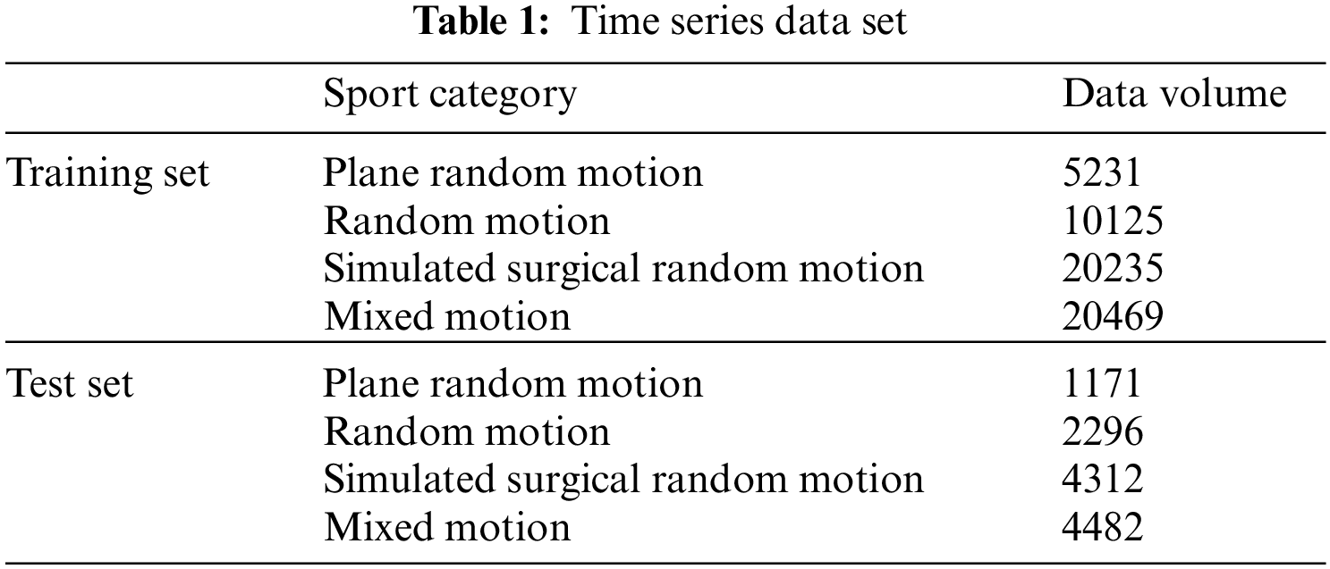
The data set selected in this paper is obtained by processing the time series data. Multiple data can be obtained for the same data series according to different time steps and mean square parameters. The data is classified according to the motion category of the time series. The sequence data is shown in the Table 1.
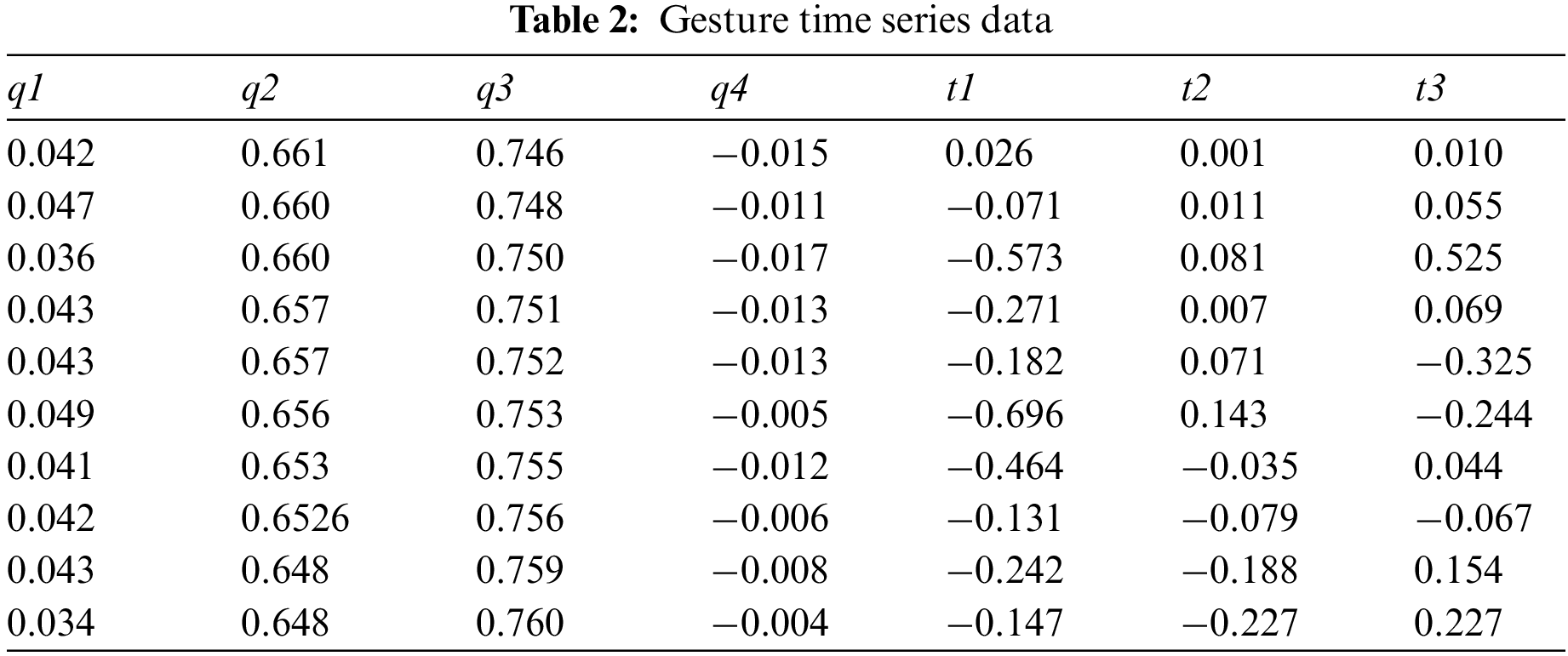
In the specific experiment, the above data are sliced according to different demand steps, and the training data can be obtained by sampling. The plane random motion data in the training data is used to preliminarily train the model, and select the step size and sampling period, to find the preliminary parameter range suitable for the model. Some of the processed data in the above time series data are shown in Table 2.
3.1 Surgical Instrument Matching Algorithm
In the process of surgical instrument matching, there are mainly two kinds of problems, that is, single surgical instrument matching and multi-surgical instrument matching. During the operation, doctors often need to use a variety of puncture tools, and there are situations where the surgeon has to cross surgical instruments between surgeries, which can lead to the problems of staggered positioning and disordered sequence of positioning markers. Therefore, this paper analyzes and studies the actual situation encountered in the process of manipulator matching, and puts forward a multi-surgical instrument matching algorithm suitable for this paper. The positioning mark points on multiple surgical instruments are imaged in one of the cameras, as shown in Fig. 1.
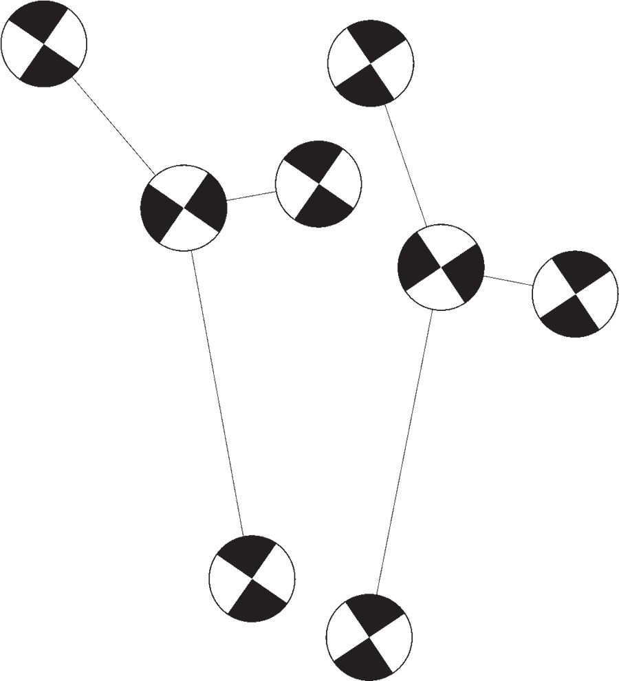
Figure 1: Schematic diagram of multiple surgical instruments
Bouguet stereo correction is to make the baseline of the two cameras parallel to the camera’s imaging plane after correction, so that the poles are at infinity. At the same time, the optical axes of the left and right cameras are parallel, and the ordinates of the imaging points on the imaging plane of the left and right cameras are the same. After correction, feature point matching can be carried out only in the small range image area consistent with the ordinate of the point to be matched, which can greatly reduce the matching time, reduce the target matching error rate, and avoid the complex situation of multi-point corresponding pole line crossing in the opposite pole geometry. In this paper, Bouguet stereo correction method [39] is used to make the corresponding matching points on a straight line, simplify the matching process, reduce the matching error rate.
The principle of Bouguet stereo correction is to transform the whole transformation matrix of left and right cameras
Then, according to the spatial positioning principle [40], the three-dimensional coordinate set
In addition, this paper regularly sets the angle of the black-and-white grid on the surgical instrument. Among the four black-and-white grids, the angle directions of the three black-and-white grids except the origin are the same and perpendicular to the angle direction of the black edge grid at the origin. Therefore, some points in the set that may be matched into surgical instruments can be quickly screened, so as to avoid the direct violent matching between all points in the set and make the matching algorithm more efficient. The matching diagram of multiple surgical instruments obtained by the above method is shown in Fig. 2.
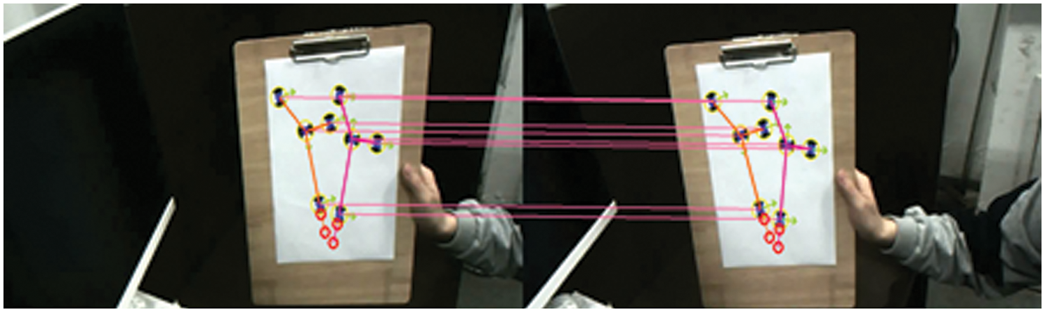
Figure 2: Matching diagram of multiple surgical instruments
3.2 Gesture Analysis Based on Rigid Body Characteristics
The specific process of surgical instrument gesture resolution is to use the four positioning markers on the surgical instrument to obtain the known information of point set
Singular value decomposition (SVD) and quaternion method are often used to solve such problems [41]. Compared with the rotation matrix, quaternion has the advantages of convenient storage and concise representation. At the same time, it avoids the problem of coplanar deadlock in the rotation of the current Euler angle representation. At the same time, quaternion has more advantages in inversion and other operations than the matrix. Therefore, this paper uses the quaternion solution to solve the quaternion representation of the surgical instrument conversion matrix
Let the quaternion be
Quaternion conversion to rotation matrix:
Use the above method to analyze the posture of surgical instruments, as shown in the Fig. 3 below.
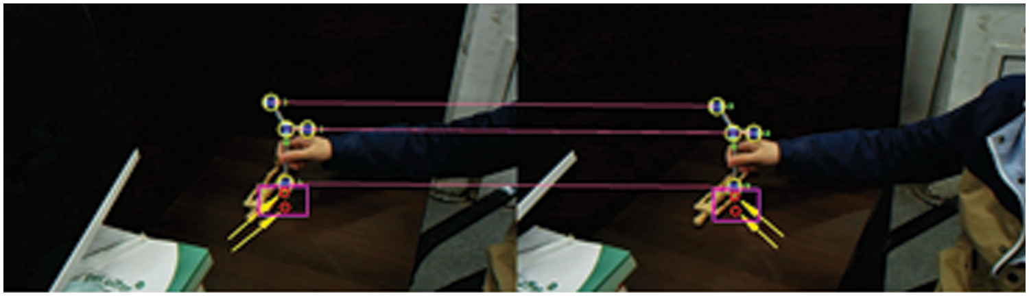
Figure 3: Posture analysis of surgical instruments
3.3 Gesture Optimization Based on Remapping
SVD is used to solve the transformation matrix between the coordinates of the camera and the surgical instrument in the coordinate system, which is the preliminary solution calculated by using the rigid body information of the surgical instrument during calibration. In order to obtain the optimal solution of the posture of the surgical instrument, this paper remaps the positioning mark points on the surgical instrument back to the left and right camera imaging planes and takes the preliminary posture solution of the surgical instrument as the starting point, The sum of the squares of the distance between the location marks projected on the left and right cameras and the detected location marks is a loss function, which is continuously optimized and iterated. The schematic diagram of reprojection optimization is shown in Fig. 4. The optimized position will be closer to the actual position.
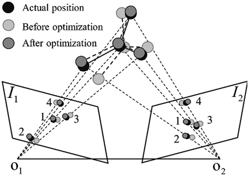
Figure 4: Optimization of surgical instruments
Then the optimization problem can be described as:
4.1 Black and White Lattice Detection Algorithm Test
In this paper, for some pictures intercepted in the experiment of real-time recognition of black-and-white lattice corner detection in the video stream, the central blue point is the recognition positioning point, and the arrow represents the direction of black-and-white lattice corner defined in the way described in this paper. The image resolution in the experiment is 1280 × 960. A round piece with a black-and-white grid corner diameter of 25 mm is pasted on the surgical instrument. The identification picture is shown in Fig. 5 below.
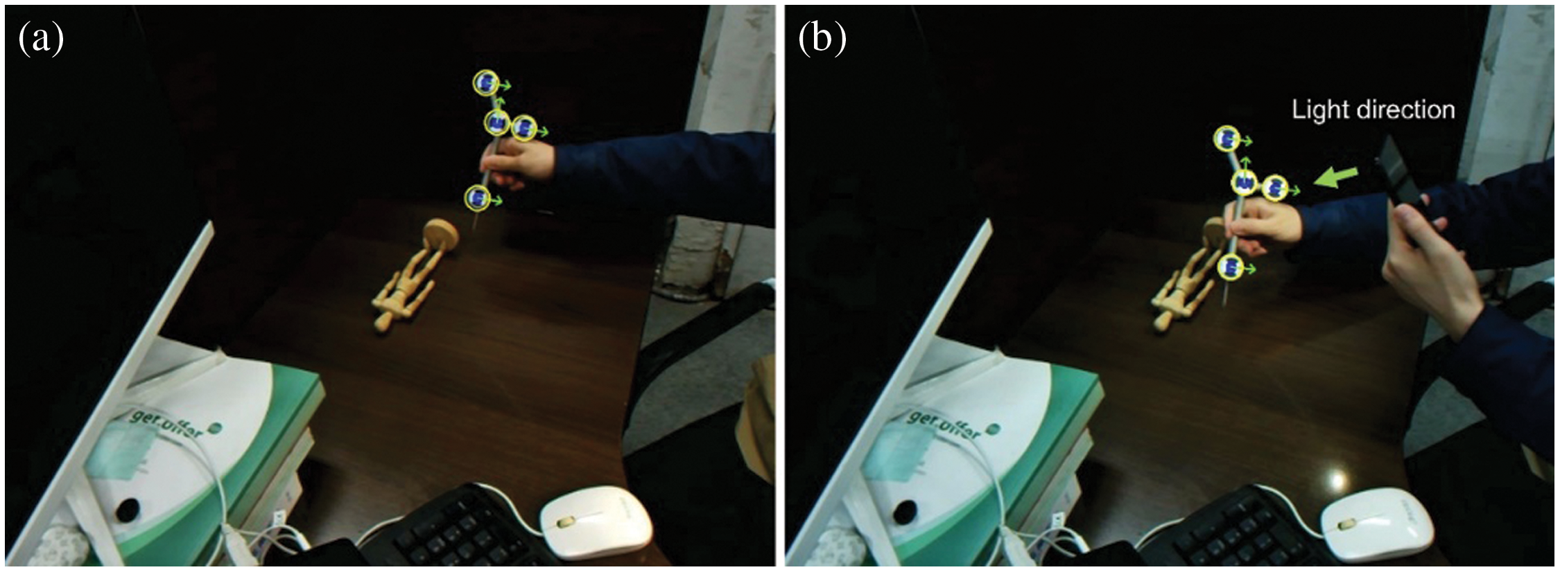
Figure 5: Experimental diagrams of black and white lattice detection. (a) Normal black-and-white grid identification diagram; (b) Complementary light black-and-white lattice recognition diagram
Fig. 5a shows the schematic diagram of normal black-and-white grid recognition, which recognizes the whole image. In conventional checkerboard recognition, many points in the recognition process of a single checkerboard, such as the proximity of two fingers, are easy to form points similar to the checkerboard. In this paper, corner screening is carried out according to the maximum regional score. As shown in the image area, the recognition is relatively stable. Fig. 5b shows the corner recognition under strong light. It can be seen from the figure that the algorithm can still identify the positioning marks robustly under a certain light intensity, indicating that the algorithm has strong robustness.
In feature point screening based on symmetry, the corner point score
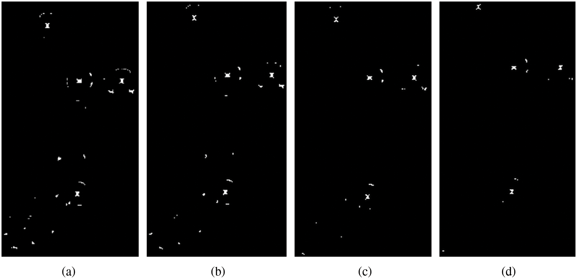
Figure 6: Screening diagram of the original algorithm. (a) thre = 50 (b) thre = 100 (c) thre = 150(d) thre = 200
The fracture diagram of cross area is shown in Fig. 7.
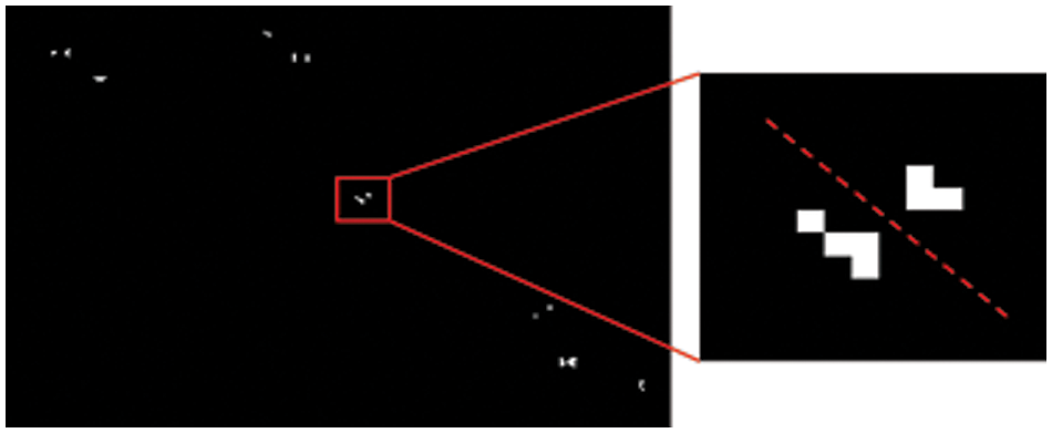
Figure 7: Fracture diagram of cross area
The effect diagram of the improved algorithm after different
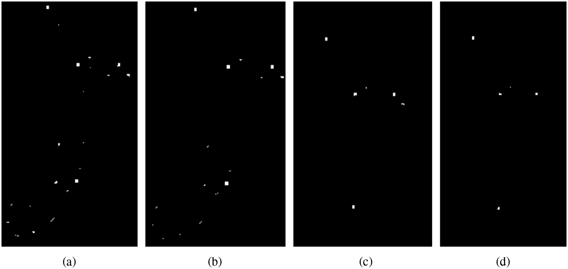
Figure 8: Schematic diagram of improved algorithm score screening (a) thre = 50 (b) thre = 100(c) thre = 150 (d) thre = 200
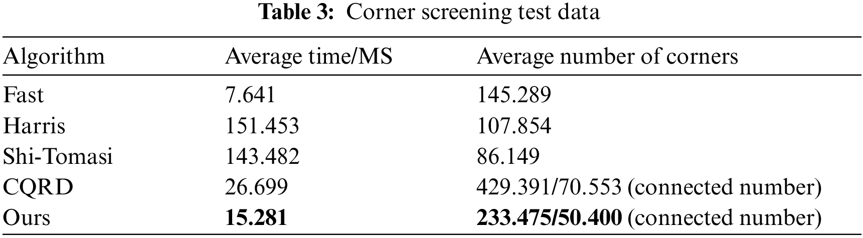
Compared with the common Fast, Harris and Shi-Tomasi corner detection algorithms, this paper tests and makes statistical analysis on 10 pictures in the calibrated pictures, and shows part of the screenshot area of one picture. The detection effect pictures are as follows in Fig. 9.
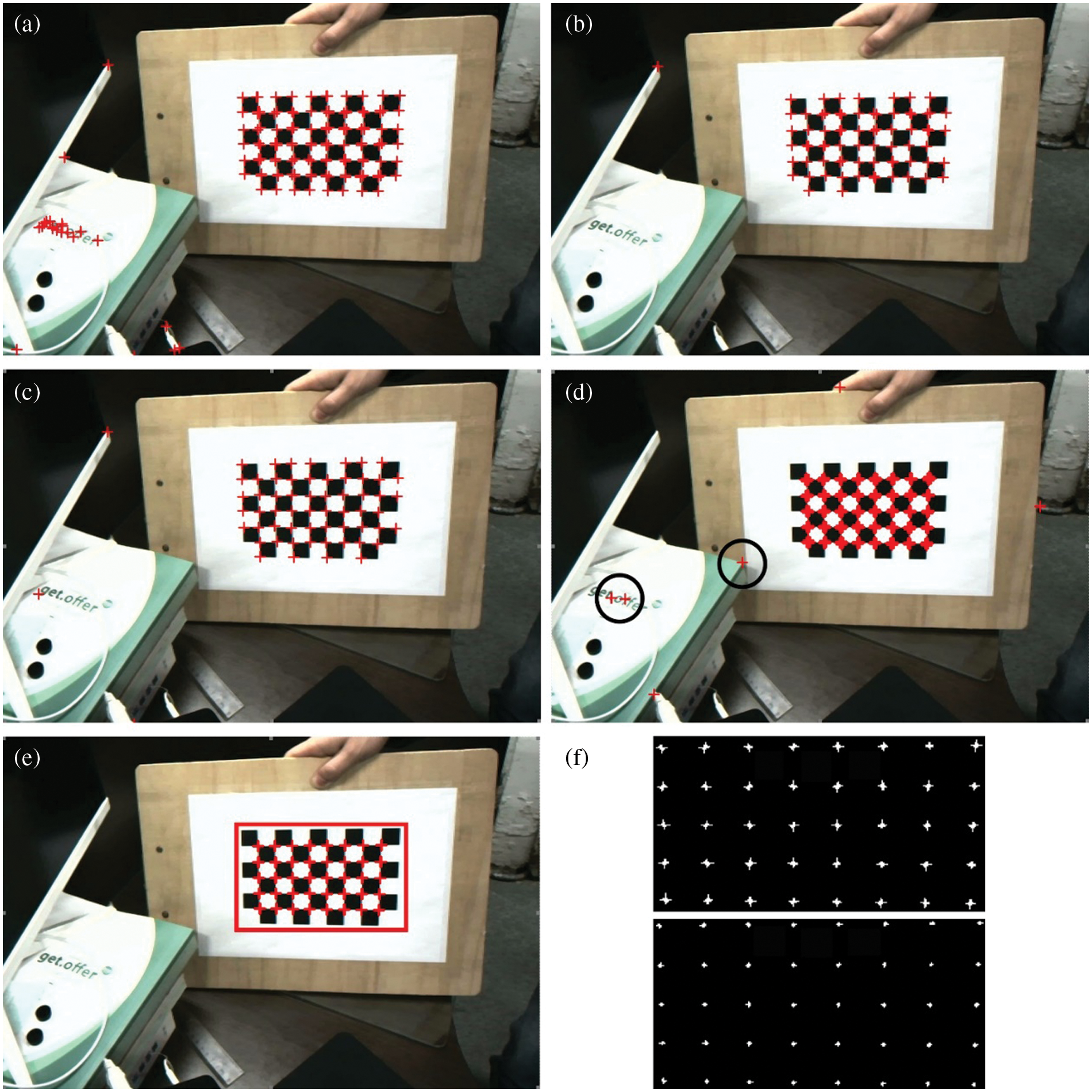
Figure 9: Corner screening diagram. (a) Fast; (b) Harris; (c) Shi-Tomasi; (d) Original algorithm; (e) The algorithm of this paper; (f) Regional distribution map of checkerboard corner points
In order to avoid the value of various algorithm thresholds, which can affect the experimental comparison, in the process of this experiment, when adjusting the threshold, the original algorithm is set to be equivalent to the threshold of this algorithm in proportion for comparison. And the other algorithms adjust the threshold from small to large intervals until the critical threshold of black-and-white grid corners can be fully identified, and fine tune around the critical threshold. It can be seen from the figure that the distribution near the corners in the Fast corner detection diagram is extremely uneven, and many non-intersecting corners will be identified. Compared with fast, Harris corner detection map is more evenly distributed near corners and can identify some non-intersecting corners. In the Shi-Tomasi corner detection diagram, the corner recognition is relatively uniform, and the number of recognitions at each position is relatively stable. Still, some non-intersecting corners can also be recognized.
The image resolution adopted in this experiment is
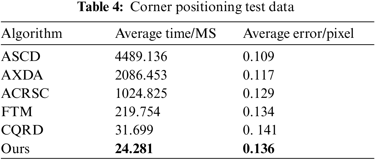
After corner screening, it is compared with the existing positioning algorithms including black-and-white lattice to further verify the certainty of corner points of black-and-white lattice. The comparison algorithms include ASCD algorithm proposed by Da et al. [42], AXDA algorithm proposed by Zhao et al. [43], ACRSC algorithm proposed by Andreas Geiger, fast template matching FTM algorithm proposed by Cheng et al. [44] and CQRD algorithm of the original text, elect 10 pictures in the corner screening test for corner positioning test, and the results are shown in Table 4.
4.2 Surgical Instrument Positioning Test
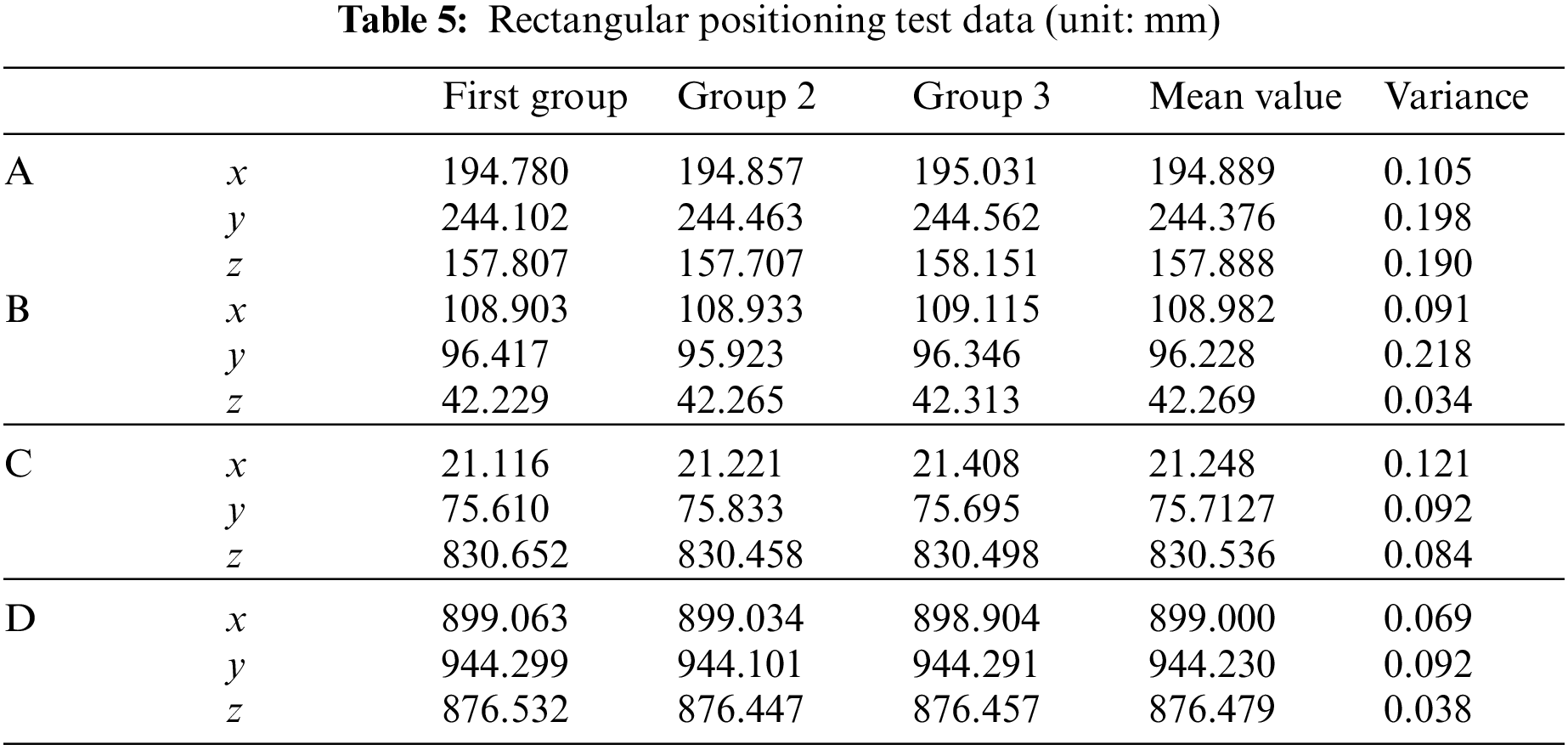
We perform feature matching on the corner points of the surgical instrument, calculate the spatial coordinates, and then calculate the surgical instrument tip according to the rigid relationship of the surgical instrument. Print the square ABCD with the side length of 100 mm on the paper, stick it to the glass plate, and place the glass plate on the stable plane, with the needle tip at the four vertices of the square for the positioning test. Table 5 shows the coordinates of measuring points A, B, C, and D.
The distance between adjacent points is shown in Table 6.
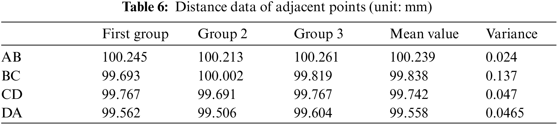
It can be seen from the table that compared with the experimental side length of 100 mm, the maximum error does not exceed 0.5 mm. In order to avoid the problem of printing accuracy, the maximum error between the calculated data with the same side length does not exceed 0.755 mm, which fully meets the system requirements.
Let the tip of the surgical instrument move in a straight line about 20 cm away against the edge of the ruler on the plane of the glass plate, and fit the motion data of the tip of the surgical instrument with MATLAB to obtain the spatial straight-line equation as:
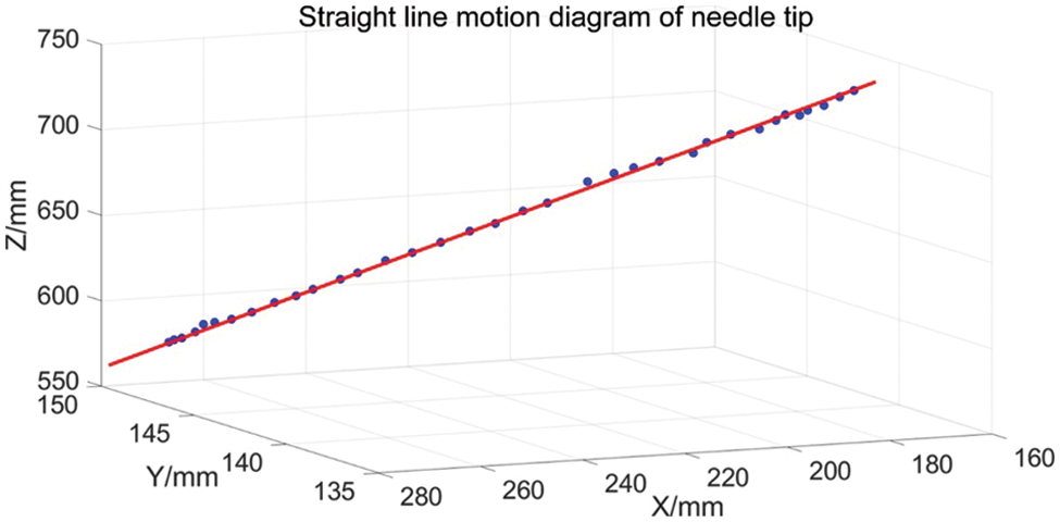
Figure 10: Linear motion of needle tip
According to the analysis of the score and screening graph of the above original text algorithm, when
According to the scoring and screening graph of the original text algorithm, it is appropriate to select
To sum up, the improved algorithm not only requires relatively few candidate points for subsequent processing but also greatly improves the robustness of the improved algorithm, especially for light and tilt.
It can be seen from Table 3 that Fast has the lowest calculation cost, but the recognition effect is the worst. Harris and Shi-Tomasi are effective, but the recognition time is the longest, which cannot meet the real-time requirements. At the same time, in the calibration picture, because the chessboard picture has good imaging, Fast, Harris and Shi-Tomasi detection algorithms can identify corners. However, there will be missed detection in the actual detection process, and the number of missed detections is high under the above threshold conditions. Reducing the threshold will rapidly increase the number of detected disordered corners, which will seriously affect the subsequent corner processing effect. This paper adopts the idea of Fast, filters most non-corner points in advance, speeds up the speed of finding corner points in the smooth area, and uses the low-resolution image to extract seed points, which can double the amount of calculation, significantly reducing the total calculation time, and the corner extraction quality is good. In addition, it can be seen that the corner extraction algorithm in this paper is also more accurate.
It can be seen from Table 4 that the accuracy of ASCD, AXDA and ACRSC is relatively high, but the running time is far greater than the real-time requirements. Among them, ASCD has the highest accuracy, and the accuracy described in the original text can reach 0.09 pixels. Due to the equipment limitation, the test data is not ideal in this experiment as described in this paper. The error of the CQRD algorithm is similar to that in this paper, but its corner area is scattered, so it is slightly lower than in this paper. Although the speed of the FTM algorithm has been improved a lot, it still needs to meet the real-time requirements, and the effect of tilt corner detection could be better. The accuracy of this paper is slightly higher than that of the original text, and the other algorithms are slightly lower, and the average running time is about 24.281 ms. Due to the slow movement of the surgical instruments, the posture estimation of the surgical instruments in the later stage only needs to scan the full image on the low-resolution image at a fixed interval, and only the left and right image surgical instrument areas are processed in the rest of the time, and the average time can achieve real-time. It meets system requirements.
This paper studies the selection of surgical instruments, the recognition algorithm of black-and-white grid position marks and its influencing factors on the positioning accuracy of surgical instruments, and makes an experimental analysis. An improved black-and-white lattice detection algorithm based on symmetry is proposed. The symmetry operator is used for initial extraction, and then the corners are further extracted according to the regional and marginal diagonal points. Experiments show the stability and robustness of the improved algorithm. The matching method of feature points and the matching algorithm of surgical instruments are proposed. In addition, according to the rigid body characteristics of surgical instruments, the gesture parameters of surgical instruments are solved, and the estimated gesture accuracy is optimized by the remapping method. The experiment verifies the accuracy of the final results.
However, there are also imperfections in this article that can be improved, for example: In this paper, only the direction information of the corners of the black-and-white lattice is considered, and the size problem is not considered. At the same time, the surgical instruments designed in this paper can not rotate. Therefore, it is still necessary to further study the three-dimensional structure design of positioning marks of surgical instruments and the positioning algorithm with stable accuracy.
Funding Statement: This work was supported by the Sichuan Science and Technology Program (2021YFQ0003).
Conflicts of Interest: The authors declare that they have no conflicts of interest to report regarding the present study.
References
1. Bhuvaneshwari, S., Roshan, F., Anisha, R., Rajeswari, C., Sweta, B. et al. (2022). Skin lesion classification of dermoscopic images using machine learning and convolutional neural network. Scientific Reports, 12(1), 18134. [Google Scholar]
2. Vinod, K., Lalotra, G. S., Sasikala, P., Rajput, D. S., Kaluri, R. et al. (2022). Addressing binary classification over class imbalanced clinical datasets using computationally intelligent techniques. Healthcare, 10(7), 1293. [Google Scholar]
3. Chen, X., Zhao, Z., Li, W., Li, H., Li, J. et al. (2019). Application of an image-guidance system in otolaryngology head and neck surgery. International Journal of Otolaryngology Head & Neck Surgery, 43(3), 181–186. [Google Scholar]
4. Wang, M., Li, D., Shang, X., Wang, J. (2020). A review of computer-assisted orthopedic surgery systems. International Journal of Medical Robotics and Computer Assisted Surgery, 16(5), 1–28. [Google Scholar]
5. Zheng, G., Nolte, L. P. (2015). Computer-assisted orthopedic surgery: Current state and future perspective. Frontiers in Surgery, 2(10), 66. https://doi.org/10.3389/fsurg.2015.00066 [Google Scholar] [PubMed] [CrossRef]
6. Chen, K. J., Lo, W. F., Chen, I., Chen, M. Y. C. (2021). Clinical application of a surgical navigation system for fractured dental needle retrieval. British Journal of Oral and Maxillofacial Surgery, 59(2), 256–257. https://doi.org/10.1016/j.bjoms.2020.12.002 [Google Scholar] [PubMed] [CrossRef]
7. Lucidi, G. A., Grassi, A., Paolo, S. D., Agostinone, P., Zaffagnini, S. (2021). The lateral femoral notch sign is correlated with increased rotatory laxity after anterior cruciate ligament injury: Pivot shift quantification with a surgical navigation system. The American Journal of Sports Medicine, 49(3), 649–655. https://doi.org/10.1177/0363546520982002 [Google Scholar] [PubMed] [CrossRef]
8. Erik, E., Gustav, B., Rami, N., Paul, G., Adrian, E. T. (2018). A novel augmented-reality-based surgical navigation system for spine surgery in a hybrid operating room: Design, workflow, and clinical applications. Operative Neurosurgery, 18(5), 496–502. [Google Scholar]
9. Chen, X., Li, Y., Xu, L., Sun, Y., Jiang, X. (2021). A real time image-guided reposition system for the loosed bone graft in orthognathic surgery. Computer Assisted Surgery, 26(1), 1–8. https://doi.org/10.1080/24699322.2021.1874535 [Google Scholar] [PubMed] [CrossRef]
10. Retana, A., Emery, R. W., Keir, V. (2019). Removal of impacted supernumerary teeth using a dynamic surgical navigation system: A case report. Journal of Oral and Maxillofacial Surgery, 77(6), 1130–1134. https://doi.org/10.1016/j.joms.2019.01.012 [Google Scholar] [PubMed] [CrossRef]
11. Cornella, K. N., Palafox, B. A., Razavi, M. K., Loh, C. T., Markle, K. M. et al. (2019). Savi scout as a novel localization and surgical navigation system for more accurate localization and resection of pulmonary modules. Surgical Innovation, 26(4), 469–472. [Google Scholar] [PubMed]
12. Nakamura, S., Hayashi, Y., Kawaguchi, K., Fukui, T., Hakiri, S. et al. (2020). Clinical application of a surgical navigation system based on virtual thoracoscopy for lung cancer patients: Real time visualization of area of lung cancer before induction therapy and optimal resection line for obtaining a safe surgical margin during surgery. Journal of Thoracic Disease, 12(3), 672–679. [Google Scholar] [PubMed]
13. Satoshi, K., Byunghyun, C., Jun, M., Junichi, I., Katsunori, T. et al. (2020). Surgical navigation improves renal parenchyma volume preservation in robot-assisted partial nephrectomy: A propensity score matched comparative analysis. The Journal of Urology, 204(1), 149–156. [Google Scholar]
14. He, K., Chi, C., Li, D., Zhang, J., Chen, X. et al. (2020). Resection and survival data from a clinical trial of glioblastoma multiforme-specific IRDye800-BBN fluorescence-guided surgery. Bioengineering & Translational Medicine, 6(1), 256–267. [Google Scholar]
15. Levin, A. A., Klimov, D. D., Nechunaev, A. A., Vorotnikov, A. A., Prokhorenko, L. S. et al. (2020). The comparison of the process of manual and robotic positioning of the electrode performing radiofrequency ablation under the control of a surgical navigation system. Scientific Reports, 10(1), 1–11. [Google Scholar]
16. Janssen, N., Kaufmann, M., Santilli, A., Jamzad, A., Fichtinger, G. (2020). Navigated tissue characterization during skin cancer surgery. International Journal of Computer Assisted Radiology and Surgery, 15(10), 1665–1672. https://doi.org/10.1007/s11548-020-02200-4 [Google Scholar] [PubMed] [CrossRef]
17. Ma, C., Chen, G., Zhang, X., Ning, G., Liao, H. (2019). Moving-tolerant augmented reality surgical navigation system using autostereoscopic three-dimensional image overlay. IEEE Journal of Biomedical and Health Informatics, 23(6), 248493. https://doi.org/10.1109/JBHI.2018.2885378 [Google Scholar] [PubMed] [CrossRef]
18. Chen, L., Zhang, F., Zhan, W., Gan, M., Sun, L. (2020). Optimization of virtual and real registration technology based on augmented reality in a surgical navigation system. Biomedical Engineering Online, 19(1), 477–496. https://doi.org/10.1186/s12938-019-0745-z [Google Scholar] [PubMed] [CrossRef]
19. Lai, M., Skyrman, S., Shan, C., Babic, D., Homan, R. et al. (2020). Fusion of augmented reality imaging with the endoscopic view for endonasal skull base surgery; a novel application for surgical navigation based on intraoperative cone beam computed tomography and optical tracking. PLoS One, 15(1), 229–234. [Google Scholar]
20. Akira, T., Toru, K. (2020). Advanced surgical navigation system using augmented reality technology. Clinical Oral Implants Research, 31(S20), 154. https://doi.org/10.1111/clr.96_13644 [Google Scholar] [CrossRef]
21. Xu, B., Yang, Z., Jiang, S., Zhou, Z., Yin, S. (2020). Design and validation of a spinal surgical navigation system based on spatial augmented reality. SPINE, 45(23), E1627–E1632. https://doi.org/10.1097/BRS.0000000000003666 [Google Scholar] [PubMed] [CrossRef]
22. Zuo, Y., Jiang, T., Dou, J., Yu, D., Huang, G. (2020). A novel evaluation model for a mixed-reality surgical navigation system: Where Microsoft HoloLens meets the operating room. Surgical Innovation, 27(2), 704–705. https://doi.org/10.1177/1553350620985324 [Google Scholar] [PubMed] [CrossRef]
23. Siemionow, K., Katchko, K., Lewicki, P., Luciano, C. (2020). Augmented reality and artificial intelligence-assisted surgical navigation: Technique and cadaveric feasibility study. Journal of Craniovertebral Junction and Spine, 11(2), 81–85. https://doi.org/10.4103/jcvjs.JCVJS_48_20 [Google Scholar] [PubMed] [CrossRef]
24. Seidl, M., Weinhold, B., Jacobsen, L., Rasmussen, O. F., Werner, M. et al. (2020). Critical assessment of staining properties of a new visualization technology: A novel, rapid and powerful immunohistochemical detection approach. Histochemistry and Cell Biology, 154(6), 663–669. https://doi.org/10.1007/s00418-020-01906-5 [Google Scholar] [PubMed] [CrossRef]
25. Yang, J., Chen, R., Zhu, W., Fang, C. (2020). Digital intelligent technology assisted three-dimensional laparoscopic extended left hepatectomy with resection of the middle hepatic vein (Video). Surgical Oncology, 35(8), 426–427. https://doi.org/10.1016/j.suronc.2020.09.006 [Google Scholar] [PubMed] [CrossRef]
26. Tai, Y. H., Wei, L., Zhou, H. L., Li, Q., Huang, X. Q. et al. (2019). Machine learning-based haptic-enabled surgical navigation with security awareness. Concurrency and Computation: Practice and Experience, 31(19), 490–498. https://doi.org/10.1002/cpe.4908 [Google Scholar] [CrossRef]
27. Pfeiffer, M., Riediger, C., Weitz, J., Speidel, S. (2019). Learning soft tissue behavior of organs for surgical navigation with convolutional neural networks. International Journal of Computer Assisted Radiology and Surgery, 14(7), 1147–1155. https://doi.org/10.1007/s11548-019-01965-7 [Google Scholar] [PubMed] [CrossRef]
28. Atzigen, M. V., Liebmann, F., Hoch, A., Bauer, D. E., Snedeker, J. G. et al. (2020). Holoyolo: A proof of concept study for marker less surgical navigation of spinal rod implants with augmented reality and on device machine learning. The International Journal of Medical Robotics and Computer Assisted Surgery, 17(1), 2184–2195. [Google Scholar]
29. Zhou, Z., Wu, B., Duan, J., Zhang, X., Liang, Z. (2017). Optical surgical instrument tracking system based on the principle of stereo vision. Journal of Biomedical Optics, 22(6), 65–75. https://doi.org/10.1117/1.JBO.22.6.065005 [Google Scholar] [PubMed] [CrossRef]
30. Jiang, G. W., Luo, M. Z., Bai, K. Q. (2019). Optical positioning technology of an assisted puncture robot based on binocular vision. International Journal of Imaging Systems and Technology, 29(2), 180–190. https://doi.org/10.1002/ima.22303 [Google Scholar] [CrossRef]
31. Wang, J., Zhang, S., Wang, Y., Zhu, Z. (2021). Learning efficient multi-task stereo matching network with richer feature information. Neurocomputing, 421, 151–160. [Google Scholar]
32. Wang, J. X., Zhu, Q., Liu, S. Y., Wang, W. (2021). Robust line feature matching based on pair-wise geometric constraints and matching redundancy. ISPRS Journal of Photogrammetry and Remote Sensing, 172(9), 41–58. https://doi.org/10.1016/j.isprsjprs.2020.09.021 [Google Scholar] [CrossRef]
33. Chen, C. B., Li, H., Zhang, L. M. (2021). An unsupervised stereo matching cost based on sparse representation. International Journal of Wavelets, Multiresolution and Information Processing, 19(1), 205–216. [Google Scholar]
34. Zhong, F. Q., Quan, C. G. (2021). Stereo-rectification and homography-transform-based stereo matching methods for stereo digital image correlation. Measurement, 173(8), 163–175. https://doi.org/10.1016/j.measurement.2020.108635 [Google Scholar] [CrossRef]
35. Zhang, B., Zhu, D. L. (2021). Local stereo matching: An adaptive weighted guided image filtering-based approach. International Journal of Pattern Recognition and Artificial Intelligence, 35(3), 215–228. https://doi.org/10.1142/S0218001421540100 [Google Scholar] [CrossRef]
36. Yan, Y. Z., Yang, P., Yan, L., Wan, J., Sun, Y. B. et al. (2018). Automatic checkerboard detection for camera calibration using self-correlation. Journal of Electronic Imaging, 27(3), 033014. https://doi.org/10.1117/1.JEI.27.3.033014 [Google Scholar] [CrossRef]
37. Yang, Z., Liu, J., Hong, H., Fang, T. (2018). Checkerboard image processing under uneven illumination for robust Harris corner detection in camera calibration. Tenth International Conference on Digital Image Processing (ICDIP 2018), 1080664. China Normal University, Shanghai, China. https://doi.org/10.1117/12.2503575 [Google Scholar] [CrossRef]
38. Wang, G., Zheng, H., Zhang, X. (2022). A robust checkerboard corner detection method for camera calibration based on improved YOLOX. Frontiers in Physics, 9, 819019. https://doi.org/10.3389/fphy.2021.819019 [Google Scholar] [CrossRef]
39. Wang, S., Yang, J. (2019). Parking robot obstacle detection system based on binocular vision. Intelligent Computer and Applications, 9(4), 79–81+86. [Google Scholar]
40. Chen, X., Wang, Y., Zhu, G., Zhang, W., Zhou, G. et al. (2020). Influence of multi-angle input of intraoperative fluoroscopic images on the spatial positioning accuracy of the C-arm calibration-based algorithm of a CAOS system. Medical & Biological Engineering & Computing, 58(3), 559–572. https://doi.org/10.1007/s11517-019-02112-9 [Google Scholar] [PubMed] [CrossRef]
41. Eggert, D. W., Lorusso, A., Fisher, R. B. (1997). Estimating 3-D rigid body transformations: A comparison of four major algorithms. Machine Vision and Applications, 9(5–6), 272–290. https://doi.org/10.1007/s001380050048 [Google Scholar] [CrossRef]
42. Da, S. T., Paulo, J., Vaz, M. A. (2007). Accurate subpixel corner detection on planar camera calibration targets. Optical Engineering, 46(10), 107–116. [Google Scholar]
43. Zhao, F. Q., Wei, C. M., Wang, J. Z., Tang, J. (2011). An automated X-corner detection algorithm (AXDA). Journal of Software, 6(5), 791–797. https://doi.org/10.4304/jsw.6.5.791-797 [Google Scholar] [CrossRef]
44. Cheng, X., Zhang, Y., Tian, J. (2020). Fast corner detection method based on template matching. Computer Engineering, 46(7), 222–227. [Google Scholar]
Cite This Article
 Copyright © 2023 The Author(s). Published by Tech Science Press.
This work is licensed under a Creative Commons Attribution 4.0 International License , which permits unrestricted use, distribution, and reproduction in any medium, provided the original work is properly cited.
 Downloads
 Citation Tools