
 Submit a Paper
 Propose a Special lssue
 Open Access
ARTICLE

Analysing Various Control Technics for Manipulator Robotic System (Robogymnast)
1 School of Engineering, Cardiff University, Cardiff, CF24 3AA, UK
2 Faculty of Engineering, University of Zawia, Zawia, 16418, Libya
3 Electrical and Electronic Department, Azahra Higher Institution of Sciences and Technology, Azahra, Libya
4 Department of Electrical and Electronics Engineering, Nisantasi University, Istanbul, 34398, Turkey
* Corresponding Authors: Mahmoud Mohamed. Emails: ,
Computers, Materials & Continua 2023, 75(3), 4681-4696. https://doi.org/10.32604/cmc.2023.035312
Received 16 August 2022; Accepted 04 November 2022; Issue published 29 April 2023
 View Full Text
 Download PDF
Abstract
The Robogymnast is a highly complex, three-link system based on the triple-inverted pendulum and is modelled on the human example of a gymnast suspended by their hands from the high bar and executing larger and larger upswings to eventually rotate fully. The links of the Robogymnast correspond respectively to the arms, trunk, and lower limbs of the gymnast, and from its three joints, one is under passive operation, while the remaining two are powered. The passive top joint poses severe challenges in attaining the smooth movement control needed to operate the Robogymnast effectively. This study assesses four types of controllers used for systems operation and identifies how far response stabilisation is achieved with each. The system is simulated using MATLAB Simulink, with findings generated regarding rising and settling time, as well as overshoot. The research primarily seeks to examine the application of a linear quadratic regulator controller, proportionalintegral-derivative controller, fuzzy linear quadratic regulator controller and linear quadratic regulator- proportional-integral-derivative controller for this type of system and comparisons between the different controllers to demonstrate successful performance, which highlights the claimed advantages of the proposed system.Keywords
An inverted pendulum is an ideal tool for the experimental study of control theories and an effective model for testing control policies in control engineering. There is strong non-linearity in the triple inverted pendulum, and the system is unstable. As a result of the multivariable of such systems, it is difficult to model and control their stabilizing action and swing-up. Furthermore, due to the dynamic nature of the structural components of this highly complex underactuated system, this model is particularly useful in simulations, comparative evaluations, and optimization of different control approaches, such as linear quadratic regulators (LQRs), proportional-integral-derivative (PID) controllers, or ACO algorithms, as an example [1,2].
As part of the present study, problems related to controlling the movement of a manipulator robot featuring under-actuation are addressed. Several different task types can be addressed by the multi-link robotic system, which has been extensively investigated within AI studies but represents significant scope for further investigation. In this study, the primary objective was to investigate swinging for a triple-link Robogymnast mechanism consisting of two active-power links and an overhead non-powered link [3].
This article will first describe the multilink robotic system studied, followed by a discussion of the mathematical modelling applied to the multilink robotic system. Afterwards, the robot’s behaviour is regulated through the fusion of state variables and control methods based on LQR, FLQR, PID, and LQR-PID. Modelling is done through MATLAB and is utilised for the simulation and implementation of this system, with the results then being provided and comparisons made. The paper assesses how robustly the developed controller performs, as well as its capacity to respond to unanticipated disturbance from outside the system and compares this to the other controller types applied.
This study is based on previous studies of inverted pendulum systems with multiple links focusing on a variety of applications, including:
• Examining motion problems for individuals who have issues with limb function due to disability or injury [3–6].
• Effectively controlling such systems through the exploitation of their intrinsic dynamic parameters to facilitate more energy-efficient design for machines by attaining smooth motions more similar to naturally occurring mechanisms for movement [3–6].
• Developing modelling, simulations and control of underactuated systems to lead to a more in-depth understanding of currently available control applications and optimising their applications to benefit industry and society more generally [5].
This study contributes to the literature by proposing 4 controller types for stabilizing multiple-link robots, in addition to analysing and comparing the performance of each multi-control unit. Considering the limitations of previous work, simplicity, applicability, and clarity of model controls are emphasized. The simulation findings indicate that the FLQR controller provides effective performance.
Following this introduction, Section 2 of this paper describes the system applied in the study, firstly outlining the system’s physical components before going on to present the mathematical model used. The third section sets out the design for the controllers considered in the study, and in Section 4, the results for the different cases are given using graph format. The fifth section provides a summary of the major findings and makes recommendations for further work in this area.
The Robogymnast, as a triple-link underactuated pendulum system, is illustrated in Fig. 1. This mechanism was designed and built at the School of Engineering at Cardiff University and features aluminium jointing and a frame based on SLS tubing. The system contains three linked components to represent major segments found in human anatomy, in which the first link represents the arms, link 2 the head and torso, and link 3 the lower limbs. The gymnast is linked through the first joint to a steel bar mounted using ball bearings [1]. The angle of rotation for this joint is measured using a rotary encoding device installed at a single end of the steel bar. Joint 2 connects link 1 to link 2, while joint 3 is between links 2 and 3. Joint 2 and joint 3 each have stepper motors/gearboxes through which the movement of these joints is powered, in addition to installing a potentiometer at each of the 2 joints. The STM Microcontroller controlling the robot is connected to a PC and extends out from the other side. It has a motor driver.
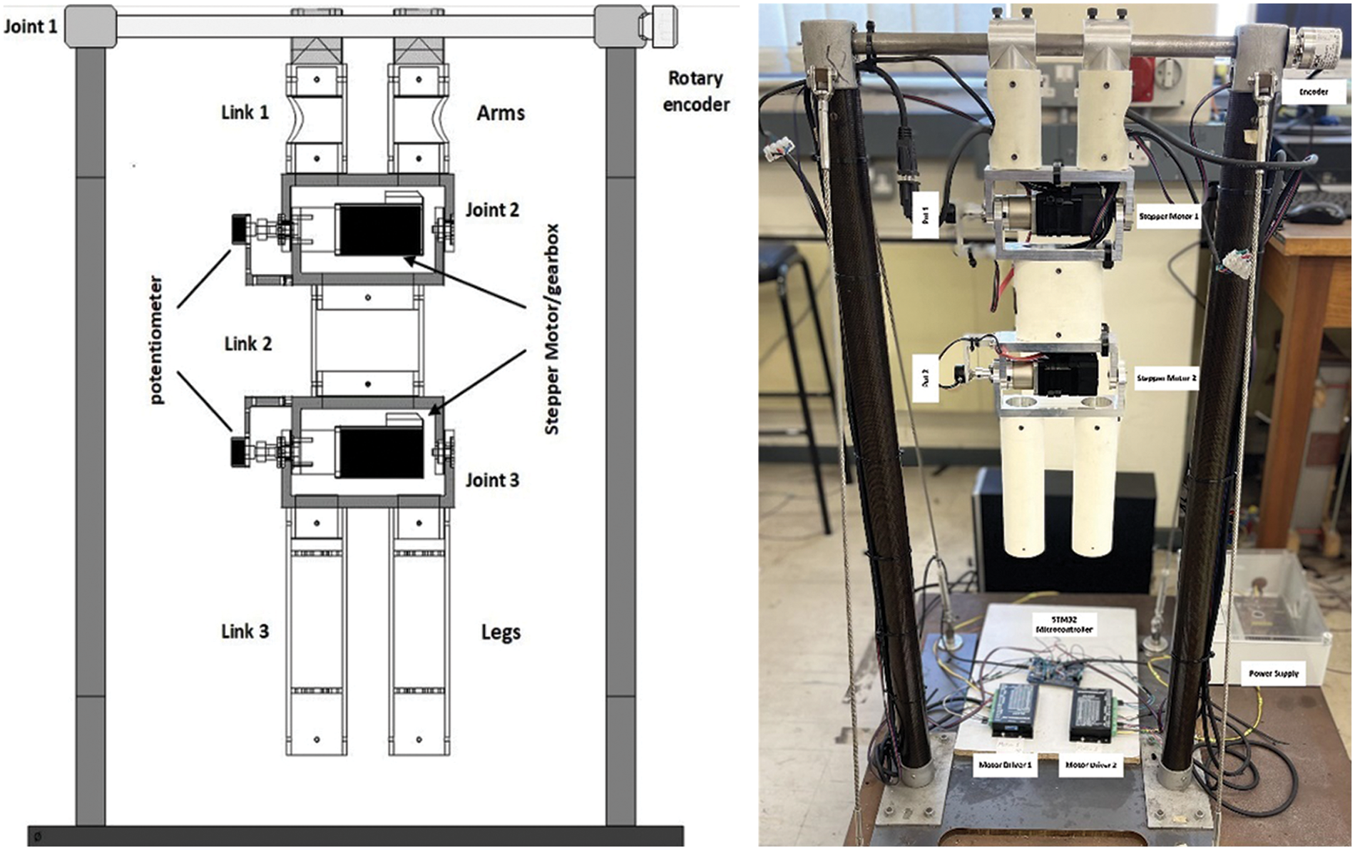
Figure 1: Robogymnast
As illustrated in the block diagram below Fig. 2, the Robogymnast is powered by 2 stepper motors, under the control of a stepper driver, which acts to achieve smooth motion. Moreover, the control system is programmed via an STM32 microcontroller, using C++ as a programming language to translate commands passed between the control unit and the Robogymnast [4,5].
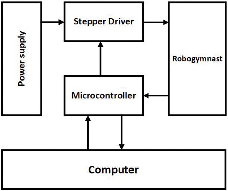
Figure 2: Illustrates the Robogymnast overall system
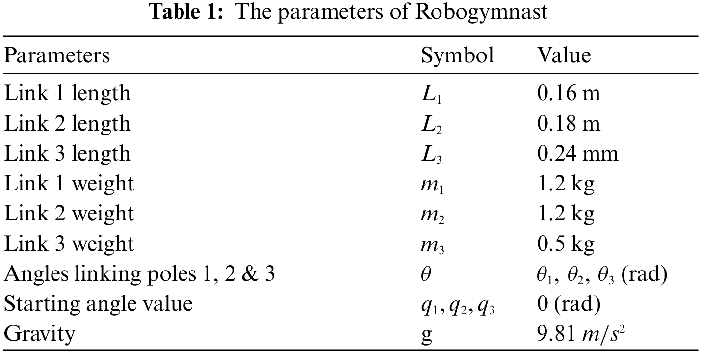
The motion equations for the Robogymnast are shown as a schematic diagram in Fig. 1, in which the derivations of the equations use Lagrange equations [7–10]. MATLAB and its relevant toolboxes are applied. The values and terms linked to each parameter are given in Table 1. Matrices for modelling are given as A, B, C, and D, while the aim of the controller is the reduction of vibration and stabilization of the pendulum’s joints as they align vertically from the top down. θ1 = θ2 = θ3 = 0 gives points of stable equilibrium related to the state of the links [4]. The system’s state space is modelled below:
The Robogymnast state vector is represented by x, with the output vector represented by y. Numerical modelling for the robot was conducted in MATLAB/toolbox, in which A, B and C were calculated:
where,
Robogymnast state-space matrices of (A, B, C, & D) are shown as:
Simulation of the Robogymnast in discrete time takes place through discretisation of Eqs. (1) and (2) before simulating them via the MATLAB command window to implement each of the matrices for mathematical modelling within the simulation and produce findings.
Controller design entails the construction and evaluation of mathematical models which are representative of physical systems and their dynamic characteristics before a controller is designed which achieves these features. The control system, which in this study refers to controllers, drivers, sensors, and motors, is responsible for the direction, command and regulation of the physical system or plant [5].
Employed-feedback proportional integral derivative (PID) controllers are frequently applied in industry and in different situations in which control must be continuously modulated [5]. In a PID controller, analysis and measurement of error occur based on the target set-point (SP) differential and process variable (PV), with real-time adaptations based on proportional (P), integral (I), and derivative (D). Practically, this leads to control functions being adjusted automatically with a high degree of accuracy and responsiveness. The PID algorithm of the controller increases system capacity, returning measured outputs to targeted inputs while minimizing deferral error [11]. PID controllers have the distinct feature that they utilize three control types, with proportional, integral, and derivative effects on their outputs, to optimize control and ensure it is as efficient as possible. Calculation and measurement of PID controller outputs use proportional, integral, and derivative terms [12,13]. With the output u(t), the following describes the PID controller:
The simulation of movements similar to those in gymnastics was conducted, and the results of this process were compared with results using other controllers. The PID controller can be shown through the equation which follows:
wherein
For the current study, MATLAB/Simulink is used to implement the PID controller (shown Fig. 3).
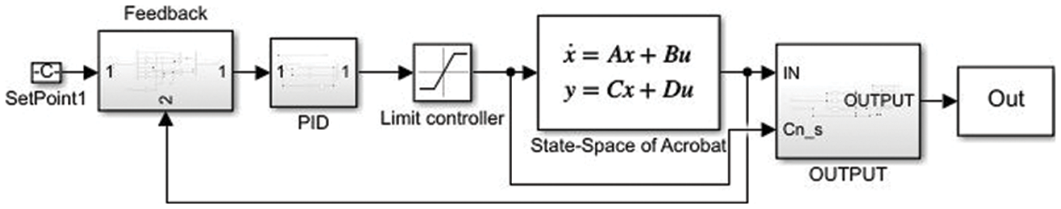
Figure 3: PID controller simulation model
The linear quadratic (LQR) controller has long been applied for high-performance, high-stability closed-loop systems, being used for effective control of feedback gain. The multivariate nature of LQR allows for simultaneous control of displacement angles across the 3-link inverted pendulum [3]. LQR was chosen based on its capacity to deal with significant disturbance events and keep systems stable with no reductions in operational performance [14–17].
In state feedback control (SFC), simplifications are made for equations for poles of the system, placed relative to K as the gain matrix, as well as state variables. Through this approach, the poles of closed-loop systems can be placed anywhere that is desired. On the other hand, in approaches to feedback control in outputs, after multiplying feedback components using the state feedback gain matrix, a comparison is made with reference values for inputs. SFC is principally applied for gain matrix calculations [4]. Applied with the LQR controller, K variables = 0.
Here, Q represents a constant symmetry positive matrix, with matrix R representing a matrix. Optimization of control is achieved through the application of the following equation to calculate P and K:
The algebraic Riccati equation is used to determine K and P values.
The current study applies the LQR controller through the MATLAB/Simulink toolbox, and this is shown in Fig. 4.
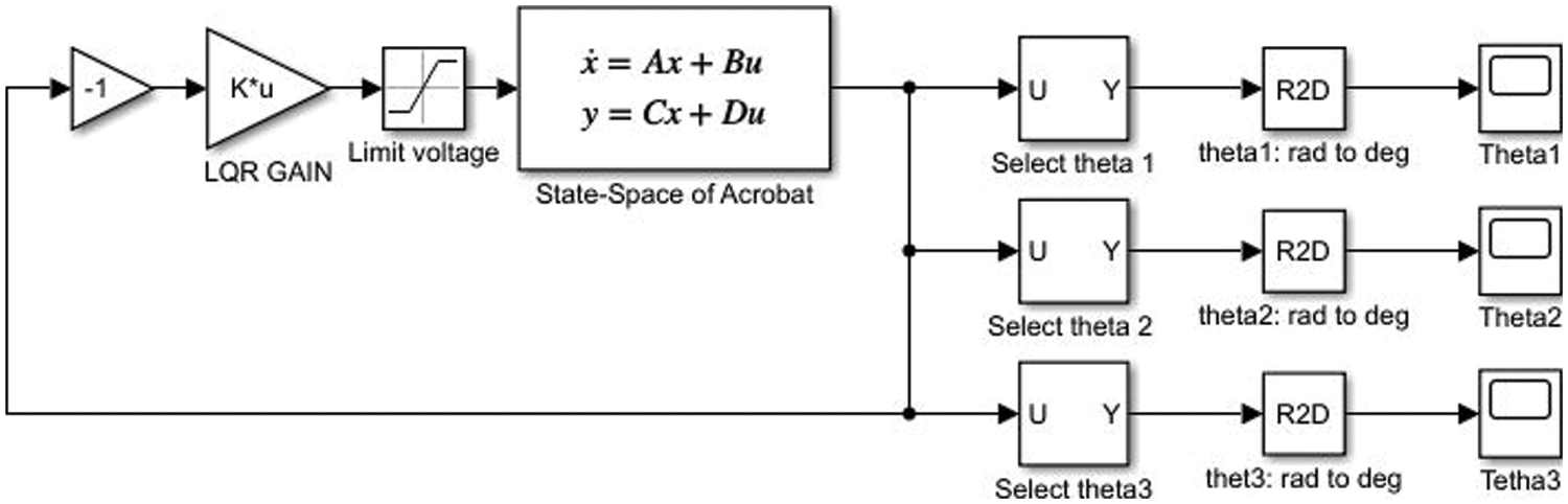
Figure 4: LQR controller simulation model
4.3 Fuzzy Linear Quadratic Regulator
The fuzzy linear quadratic regulator (FLQR) [6] controller brings together approaches of optimal control as in the linear quadratic regulator (LQR) and a rules-based fuzzy control approach. The fuzzy logic controller (FLC) utilises sets of Fuzzy Control Rules (FCRs), with fuzzy implications connecting the rules, as well as the compositional rule of inference [17–19]. FLC here supplements the use of a pre-existing controller, acting if a condition is altered. Fuzzy logic has a range of uses in manufacturing processes and systems, with FLC being applied to enhance the intelligence of the system [20,21].
Applying the Mamdani method, the fuzzy model was developed to enable modification of closed-loop controller feedback gain. Variables based on language were created by transforming the input control-signal E and EC, as well as the U output variable, resulting in: NB, meaning negative big; NM, denoting negative medium; NM, indicating negative small; Z, representing zero; PS, meaning positive small; PM for positive medium; and PB for positive big. Graphic inference was performed for the inputs and output through triangular membership functions. Inputs are error (E) and error change (EC) as shown in Fig. 5, and the output range is illustrated in Fig. 6. The FCRs applicable to the controller for the Robogymnast are described in Table 2. Fig. 8 shows a possible implementation of the Robogymnast with the FLQR controller, through Simulink [17,22].
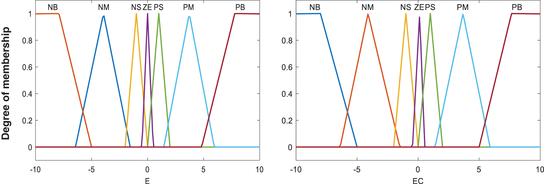
Figure 5: Membership function of fuzzy input variable (Error and Error Change)

Figure 6: Membership function of fuzzy output variable (u)
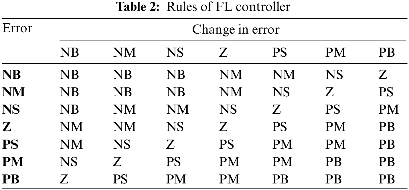
FLCs’ performance is significantly affected by the way the linguistic fuzzy rules base is structured. The current study examines these rules through assessing the robot’s dynamic behaviours.
MATLAB Simulink was used to investigate the FLQR condition as shown Fig. 7.
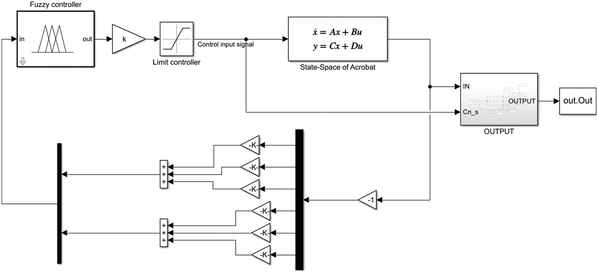
Figure 7: Implementation of FLQR on Simulink

Figure 8: LQR-PID controller simulation model
The linear quadratic regulator - proportional-integral-derivative (LQR-PID) controller utilises both LQR and PID control techniques for stabilization of the Acrobat Robot system, and findings from this system were compared to the different controller systems, with every controller type having specific benefits. PID and LQR controllers are structured differently, leading to distinct performance tuning and modelling for the closed-loop system. LQR gives a reduced rising/settling duration in comparison to PID, while PID reduces overshoot and error, as well as being simpler to implement. The two types of controllers show differences in outcomes due to their differing strategies for feedback gain matrix calculation [17,23,24]. Fig. 9 shows the PID system response for Theta 1, 2 and 3.
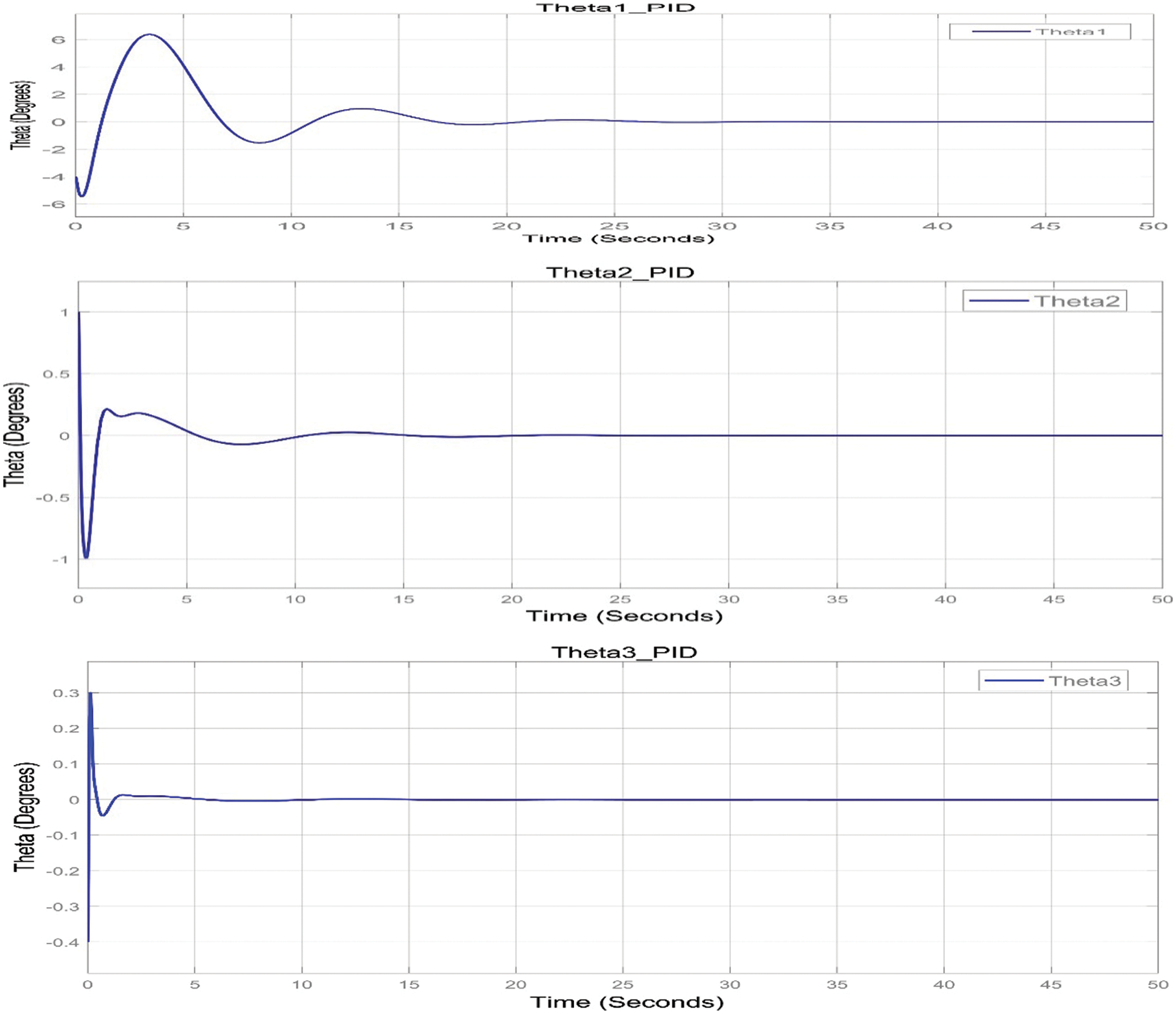
Figure 9: The step response of the system (PID)
MATLAB Simulink was utilised to determine system response for the Robogymnast, to improve controller design and assess the function of the controllers within a closed loop system. This involved investigating step responses of the system while using the various controllers [5,6]. Modelling and simulation were conducted with linear and non-linear FLQR, LQR, LQR-PID and PID controllers via the MATLAB Simulink toolbox, for stabilization of the Robogymnast as a 3-link system. Fig. 10 provides data on output responses. The findings show improvement in variables, including overshoot and rising time, for the PID controller in terms of the system’s step responses.
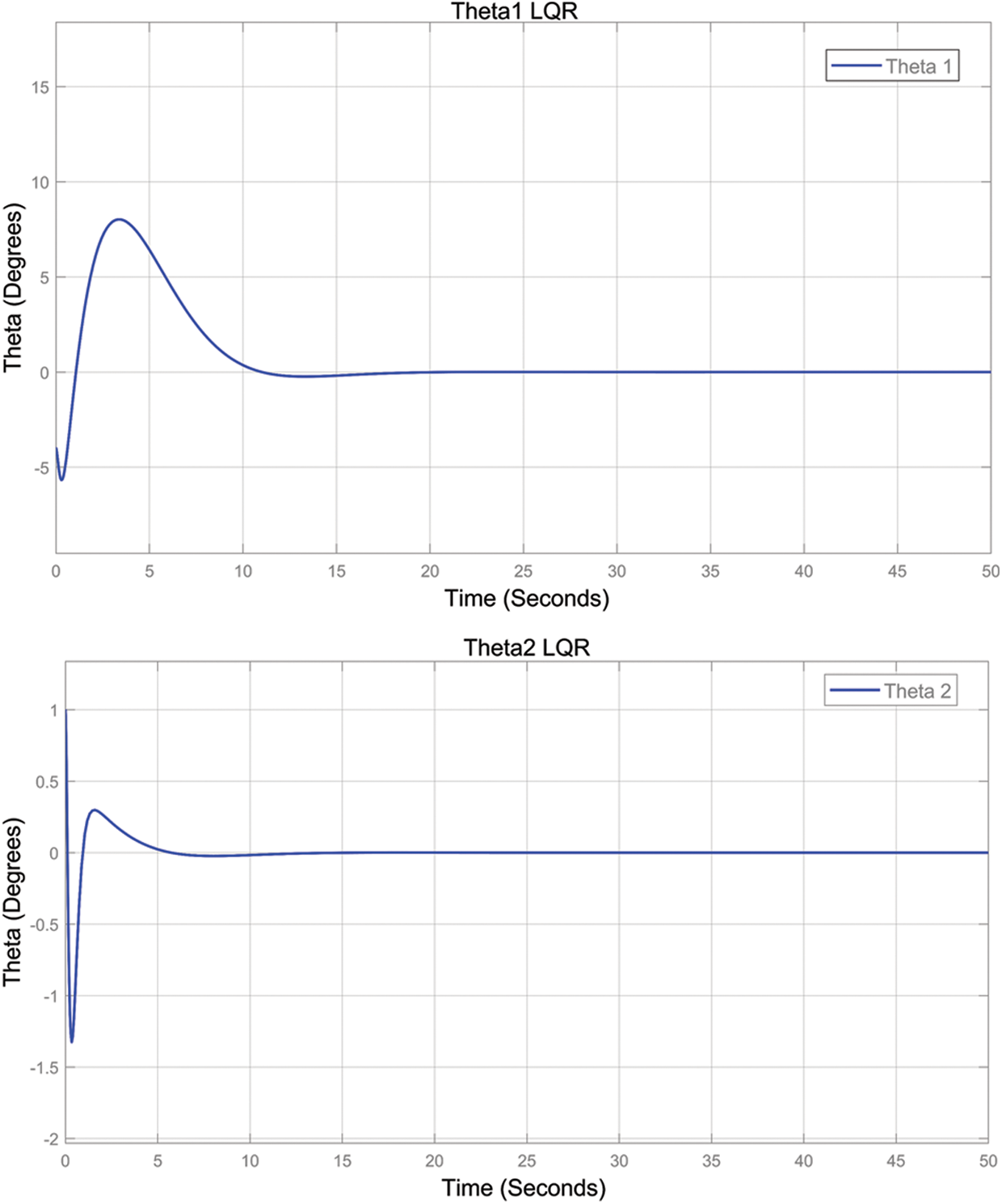
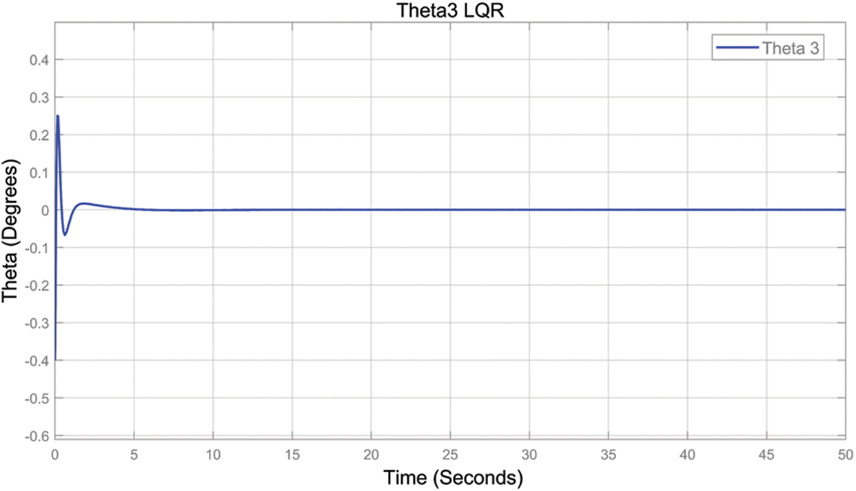
Figure 10: The step response of the system (LQR)
As shown in Fig. 11 the response of FLQR controller for the three joints displayed.
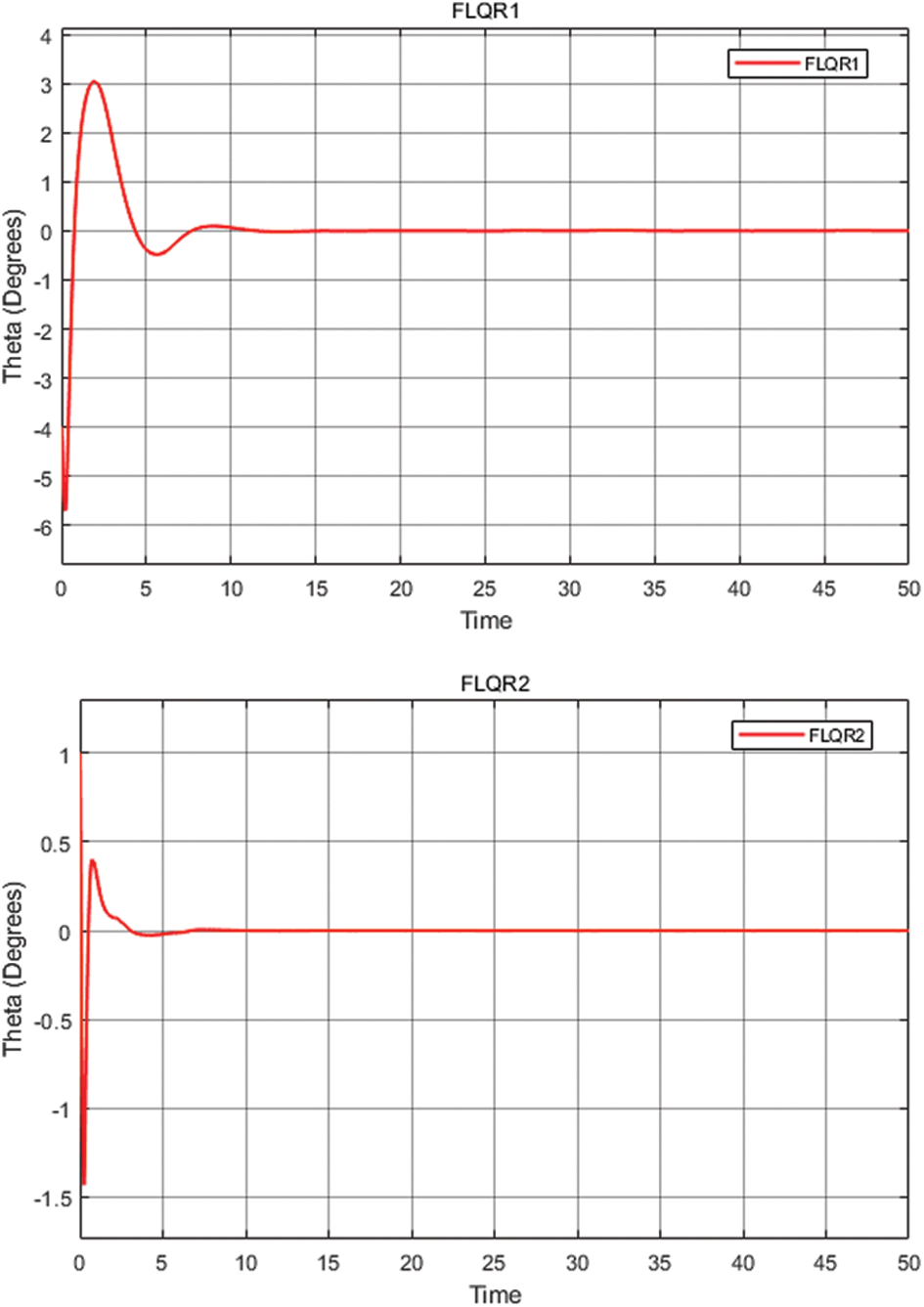
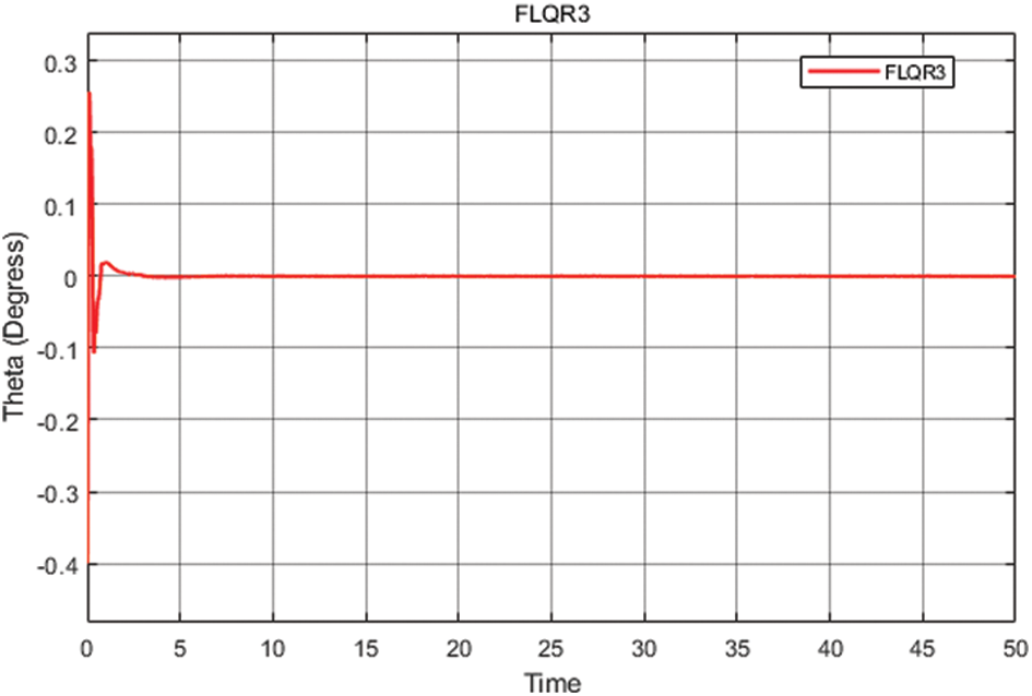
Figure 11: The step response of the system (FLQR)
A comparison is made of step-response system outputs. The controllers were applied in turn, with comparisons of overshoot (
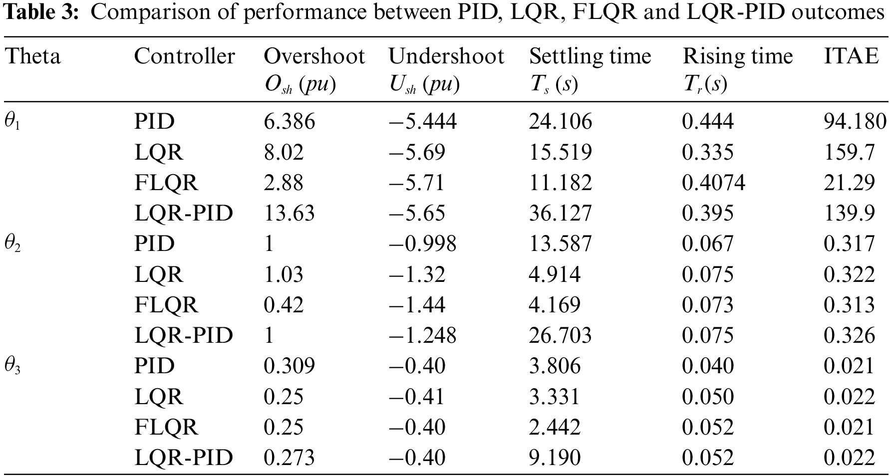
As shown in Table 3, results related to the stability of the multi-link system in three cases: upper, middle, and lower links are presented sequentially for the 4 controllers used. The comparison of responses across the 4 controllers simulated indicates that the system is stable in each case, with different outcomes, as discussed below.
In the first scenario, which examines θ1, the outcomes of overshoot (
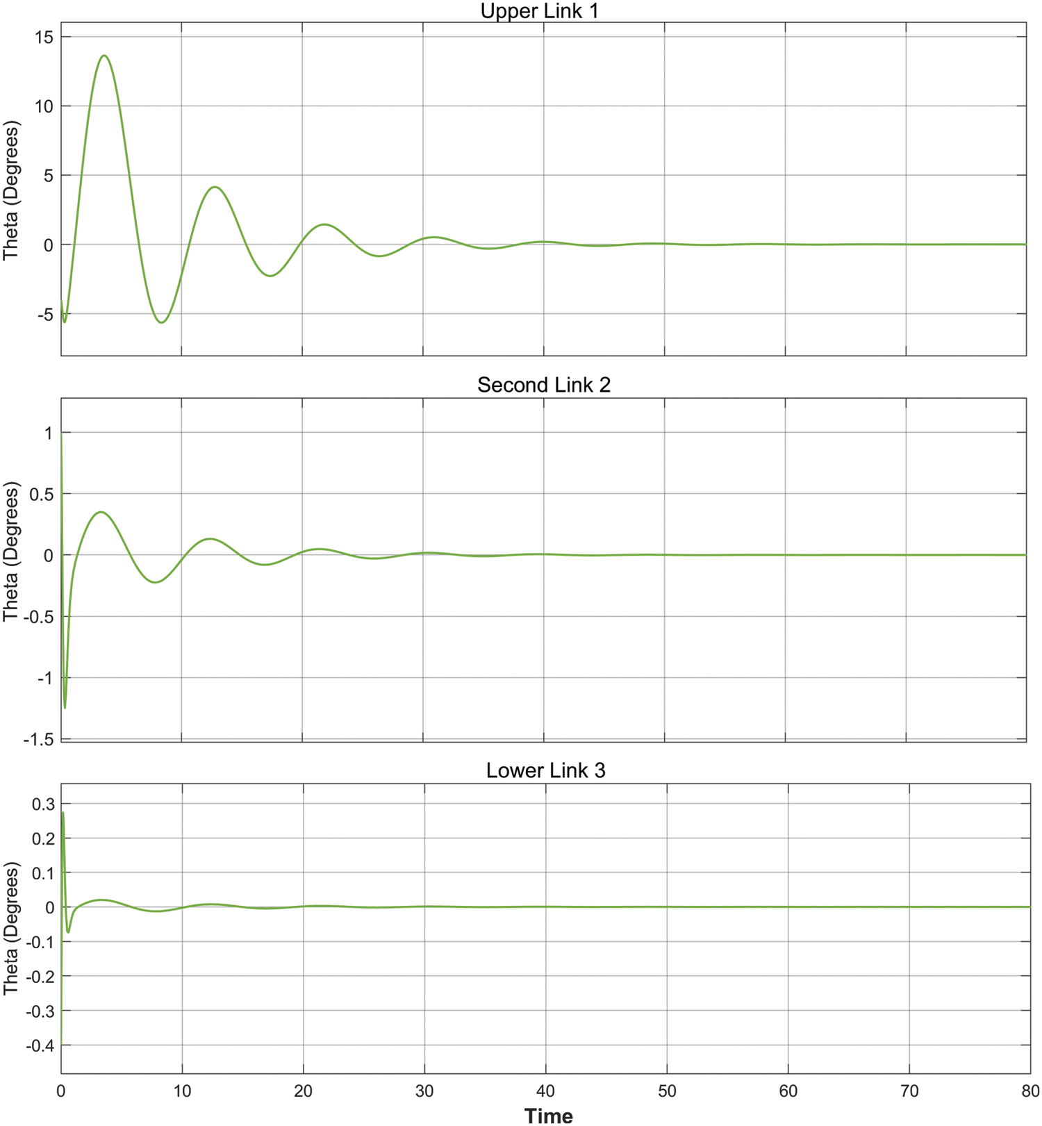
Figure 12: The step response of the system (LQR-PID)
Secondly, θ2 represent the middle link of the system in the multi-controller, and for this link, FLQR performs best for both overshoot (
Lastly, for the lower link θ3, overshoot is identical for the FLQR and LQR controllers, and undershoot differs only slightly between controllers. In addition, the shortest settling time is provided by the FLQR controller at 2.44 s, while PID provides the shortest amount in rising time at 0.04 s. IATE displays similar values for all controllers.
The findings generally show that FLQR impacts system response optimisation in a significant manner and settling times for each link are better with the FLQR than with other controllers. ITAE is also reduced across all stages with FLQR. Future investigations will consider a wider range of controller types.
This paper has reported on model creation and simulations in MATLAB Simulink for 4 controller types as applied to the Robogymnast. This work involved the development and assessment of implementation for LQR, FLQR, LQR-PID and PID controllers and assessing their relative performances against conventional controls. The initial work involved modelling the multi-link pendulum system in mathematical terms and then producing a model for simulations with a robotics manipulation using the specified controllers across different cases. The most significant systems factors: namely, under and overshoot, settling and rise time, were calculated, and the findings were compared to consider which controller was most effective. The FLQR controller showed the greatest suitability for the Robogymnast against generally used controllers, with PID being the next most effective. Further work will consider methods for optimizing results with this system.
Acknowledgement: The authors would like to thank Cardiff University/School of Engineering for accepting to pay the APC towards publishing this paper.
Funding Statement: This paper is part of the research of the corresponding author, Mahmoud Mohamed, who is sponsored by the Ministry of Higher Education and Scientific Research, Zawia University in Libya.
Conflicts of Interest: The authors declare that they have no conflicts of interest to report regarding the present study.
References
1. H. A. Ismail, M. S. Packianather, R. I. Grosvenor and E. E. Eldhukri, “The application of IWO in LQR controller design for the Robogymnast,” in 2015 SAI Intelligent Systems Conf. (IntelliSys), London, UK, pp. 274–279, 2015. [Google Scholar]
2. N. S. Bhangal, “Design and performance of LQR and LQR based fuzzy controller for double inverted pendulum system,” Journal of Image and Graphics, vol. 1, no. 3, pp. 143–146, 2013. [Google Scholar]
3. H. A. Ismail, “Intelligent model-based control of complex multi-link mechanisms,” A Ph.D. Thesis Submitted to Cardiff University, UK, 2016. [Google Scholar]
4. B. A. Samad, F. Anayi, Y. Melikhov, M. Mohamed and E. Altayef, “Modelling of LQR and fuzzy-LQR controllers for stabilisation of multi-link robotic system (Robogymnast),” in 2022 8th Int. Conf. on Automation, Robotics and Applications (ICARA), Prague, Czech Republic, pp. 33–38, 2022. [Google Scholar]
5. M. Mohamed, F. Anayi, M. Packianather, B. A. Samad and K. Yahya, “Simulating LQR and PID controllers to stabilise a three-link robotic system,” in 2022 2nd Int. Conf. on Advance Computing and Innovative Technologies in Engineering (ICACITE), Greater Noida, India, pp. 2033–2036, 2022. [Google Scholar]
6. B. Abdul Samad, M. Mohamed, F. Anayi and Y. Melikhov, “An investigation of various controller designs for multi-link robotic system (Robogymnast),” Knowledge, vol. 2, no. 3, pp. 465–486, 2022. [Google Scholar]
7. E. E. Eldukhri and D. T. Pham, “Autonomous swing-up control of a three-link robot gymnast,” Proceedings of the Institution of Mechanical Engineers, Part I: Journal of Systems and Control Engineering, vol. 224, no. 7, pp. 825–833, 2010. [Google Scholar]
8. K. G. Eltohamy and C. Y. Kuo, “Nonlinear optimal control of a triple link inverted pendulum with single control input,” International Journal of Control, vol. 69, no. 2, pp. 239–256, 1998. [Google Scholar]
9. C. Sun, H. Gao, W. He and Y. Yu, “Fuzzy neural network control of a flexible robotic manipulator using assumed mode method,” IEEE Transactions on Neural Networks and Learning Systems, vol. 29, no. 11, pp. 5214–5227, 2018. [Google Scholar] [PubMed]
10. P. Nordfeldt and T. Hägglund, “Decoupler and PID controller design of TITO systems,” Journal of Process Control, vol. 16, no. 9, pp. 923–936, 2006. [Google Scholar]
11. H. Purnawan, M. Mardlijah and E. B. Purwanto, “Design of linear quadratic regulator (LQR) control system for flight stability of LSU-05,” Journal of Physics: Conference Series, vol. 890, no. 1, pp. 1–6, 2017. [Google Scholar]
12. H. G. Kamil, “Intelligent model-based control of complex three-link mechanisms,” A Ph.D. Thesis Submitted to Cardiff University, UK, 2015. [Google Scholar]
13. V. Bakircioǧlu, M. Arif Sen and M. Kalyoncu, “Optimization of PID controller based on the Bees Algorithm for one leg of a quadruped robot,” MATEC Web of Conferences, vol. 42, pp. 3–6, 2016. [Google Scholar]
14. R. A. Paz, “The design of the PID controller,” Computer Engineering, vol. 8, pp. 1–23, 2001. https://www.researchgate.net/publication/237528809_The_Design_of_the_PID_Controller [Google Scholar]
15. P. Boscariol, L. Scalera and A. Gasparetto, “Nonlinear control of multibody flexible mechanisms: A model-free approach,” Applied Sciences, vol. 11, no. 3, pp. 1–14, 2021. [Google Scholar]
16. R. Mohammadi Asl, A. Mahdoudi, E. Pourabdollah and G. Klančar, “Combined PID and LQR controller using optimized fuzzy rules,” Soft Computing, vol. 23, no. 13, pp. 5143–5155, 2019. [Google Scholar]
17. B. A. Samad, M. Mohamed, F. Anayi and Y. Melikhov, “A hybrid Fuzzy approach of different controllers to stabilize a 3-link swinging robotic (Robogymnast),” in 2022 2nd Int. Conf. on Advance Computing and Innovative Technologies in Engineering (ICACITE), Greater Noida, India, pp. 2432–2437, 2022. [Google Scholar]
18. K. K. Yit, P. Rajendran and L. K. Wee, “Proportional-derivative linear quadratic regulator controller design for improved longitudinal motion control of unmanned aerial vehicles,” International Journal of Micro Air Vehicles, vol. 8, no. 1, pp. 41–50, 2016. [Google Scholar]
19. E. S. Varghese, A. K. Vincent and V. Bagyaveereswaran, “Optimal control of inverted pendulum system using PID controller, LQR and MPC,” in IOP Conf. Ser. Materials Science and Engineering, Vellore, India, pp. 1–15, 2017. [Google Scholar]
20. E. Vinodh Kumar and J. Jerome, “LQR based optimal tuning of PID controller for trajectory tracking of magnetic levitation system,” Procedia Engineering, vol. 64, no. 4, pp. 254–264, 2013. [Google Scholar]
21. S. Das, I. Pan, K. Halder, S. Das and A. Gupta, “LQR based improved discrete PID controller design via optimum selection of weighting matrices using fractional order integral performance index,” Applied Mathematical Modelling, vol. 37, no. 6, pp. 4253–4268, 2013. [Google Scholar]
22. C. Choubey and J. Ohri, “Optimized LQR-PID controller using squirrel search algorithm for trajectory tracking of a 6-DOF parallel manipulator,” preprint (Version 1) available at Research Square, 2021. [Google Scholar]
23. E. A. Alandoli, M. Z. A. Rashid and M. Sulaiman, “A comparison of PID and LQR controllers for position tracking and vibration suppression of flexible link manipulator,” Journal of Theoretical and Applied Information Technology, vol. 95, no. 13, pp. 2949–2955, 2017. [Google Scholar]
24. H. A. Ismail, E. E. Eldhukhri and M. S. Packianather, “Invasive weed optimization of swing-up control parameters for robot gymnast,” in 2014 IEEE/ASME Int. Conf. on Advanced Intelligent Mechatronics, Besançon, France, pp. 88–93, 2014. [Google Scholar]
Cite This Article
 Copyright © 2023 The Author(s). Published by Tech Science Press.
This work is licensed under a Creative Commons Attribution 4.0 International License , which permits unrestricted use, distribution, and reproduction in any medium, provided the original work is properly cited.
 Downloads
 Citation Tools