
 Submit a Paper
 Propose a Special lssue
 Open Access
ARTICLE
Explicit Topology Optimization Design of Stiffened Plate Structures Based on the Moving Morphable Component (MMC) Method
1 Department of Engineering Mechanics, State Key Laboratory of Structural Analysis for Industrial Equipment, International Research Center for Computational Mechanics, Dalian University of Technology, Dalian, 116023, China
2 Ningbo Institute of Dalian University of Technology, Ningbo, 315016, China
3 Beijing Institute of Spacecraft System Engineering, Beijing, 100094, China
* Corresponding Authors: Chang Liu. Email: ; Xu Guo. Email:
(This article belongs to the Special Issue: New Trends in Structural Optimization)
Computer Modeling in Engineering & Sciences 2023, 135(2), 809-838. https://doi.org/10.32604/cmes.2023.023561
Received 02 May 2022; Accepted 21 July 2022; Issue published 27 October 2022
 View Full Text
 Download PDF
Abstract
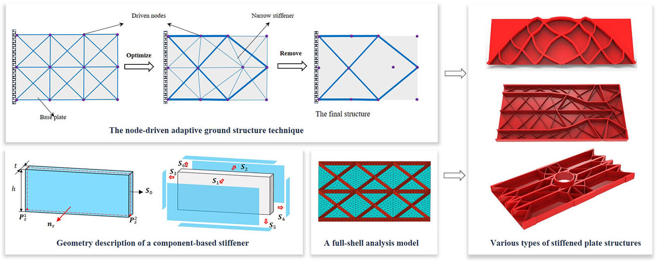
This paper proposes an explicit method for topology optimization of stiffened plate structures. The present work is devoted to simultaneously optimizing stiffeners’ shape, size and layout by seeking the optimal geometry parameters of a series of moving morphable components (MMC). The stiffeners with straight skeletons and the stiffeners with curved skeletons are considered to enhance the modeling and optimization capability of the current approach. All the stiffeners are represented under the Lagrangian-description framework in a fully explicit way, and the adaptive ground structure method, as well as dynamically updated plate/shell elements, is used to obtain optimized designs with more accurate analysis results. Compared with existing works, the proposed approach provides an explicit description of the structure. Thus, a stiffened plate structure with clear stiffener distribution and smooth geometric boundary can be obtained. Several numerical examples provided, including straight and curved stiffeners, hierarchical stiffeners, and a stiffened plate with a cutout, validate the effectiveness and applicability of the proposed approach.Graphic Abstract
Keywords
Plate structures have played an essential role in aerospace, automotive, marine and civil engineering due to their high load-bearing efficiency, lightweight construction and other excellent traits [1,2]. These structures, however, are susceptible to deformation, strength, vibration and buckling under use since their thicknesses are much smaller compared to their other dimensions. To improve the load bearing capacity of plate structures, in the past few decades, many methods have been developed to analyze and enhance their strength, stiffness, stability, dynamic performance [3–6], etc., among which the use of stiffener is one of the most efficient and cost-effective methods. This accordingly arouses great interest of researchers in the investigations of optimal design of stiffened plate structures.
As an advanced design methodology, structural optimization [7–13], including size, shape and topology optimization, is widely used to solve material distribution problems of stiffened plate structures. For example, Lagaros et al. [14] investigated the optimization design of stiffened shell structures with straight stiffening beams by using evolutionary algorithms. In [15–18], a set of thickness parameters or spacing parameters are chosen as design variables to optimize the size and shape of stiffeners, while the topological form of the stiffeners remains constant during the optimization process. Pavlovčič et al. [19,20] studied the shear strength of the steel plate with trapezoidal stiffeners from numerical and experimental aspects. Kapania et al. [21] studied the optimization results of curvilinear stiffened panels. They found that curvilinear stiffeners may lead to lighter-weight designs than straight stiffeners for certain design cases. After that, Mulani et al. [22,23] proposed a new framework to design curvilinear stiffened panels considering complex, multifunctional and aircraft structural concepts. Wang et al. [24] and Hao et al. [25] developed a novel bilevel optimization strategy based on the hybrid model to optimize the size and layout of stiffened panels with reinforced cutouts. Liu et al. [26,27] suggested a non-parametric shape optimization method for designing the stiffeners on shell structures, in which the stiffness and eigenvalue maximization problems are considered. Moreover, Wang et al. [28,29] introduced an interesting bio-inspired approach for stiffener optimization, where the optimized shape and location of non-uniform curved grid stiffeners can be found in an adaptively evolutionary way. Besides size and shape optimization applied to the stiffener design of plate structures, topology optimization, which can provide more design space and flexibility, is also extensively carried out to optimize stiffened plate structures. Lam et al. [30] suggested an automated optimization method for determining the location of stiffeners from a variable thickness plate iteratively. By introducing a second-ranked microstructure, Ansola et al. [31] introduced a second-ranked microstructure in the stiffened optimization framework and simultaneously optimized the shell’s geometry and the stiffener layout. Afonso et al. [32] developed an integrated computational tool to find the optimal material distribution of variable thickness plates and free form shells, in which topology optimization is performed using both a hybrid algorithm and a homogenization approach. Similarly, Ma et al. [33] established a generative design method based on the homogenization method and an equivalent model to optimize stiffened plates. Sigmund and his co-authors [34] successfully applied the SIMP method combined with a novel computational morphogenesis tool to full-scale aircraft wing design, where the intricate details that appeared spontaneously in the optimization process (e.g., curved spars and local plate structures) could be observed clearly. Recently, Zhang et al. [35] proposed a novel B-spline-based method for structural topology optimization. Based on this framework, Feng et al. [36] effectively utilized B-spline control parameters to characterize the stiffener distribution reinforcing the plate/shell structures. Some other latest investigations conducted on the stiffener optimization of plate structures can be referred to [37–42].
Most of the stiffened structure optimization approaches mentioned above are based on classical implicit solution frameworks that the optimized stiffeners are identified from a black-and-white pixel image, which cannot guarantee that the optimized results are clear stiffeners rather than block-like patterns. Furthermore, the implicit bitmap-like geometric representation may result in a large number of design variables and ambiguous stiffener boundaries. In order to address these problems, some new design methods for stiffened structures based on bionic inspirations and growth simulation have been developed. Mattheck et al. [43] proposed a novel technique based on the swelling function of a commercial finite-element code. Ding et al. [44] developed a growing and branching tree model to generate stiffener layout patterns inspired by natural branching systems. Ji et al. [45] employed a bionic growth approach, which combines a bionic branch model and optimization criteria, to optimize the stiffener layout of the plate/shell structures. Li et al. [46–48] proposed a novel explicit approach to perform topology optimization of stiffened structures via a biologically inspired algorithm and then used it to discover the optimal internal cooling geometries in the heat conduction system. Dong et al. [49] used an adaptive growth method to improve the buckling resistance performance of plate/shell structures by optimizing the stiffener pattern. Unlike implicit topology optimization approaches, these natural growth-based algorithms can obtain explicit stiffener layouts rather than block-like material distributions, making the optimized results more conducive to practical applications. Nevertheless, most of these methods employ smear-out technology/equivalent stiffness technology for structural response analysis, which is difficult to accurately predict the local mechanical behavior (e.g., local buckling and local stress) of stiffened plate structures. Furthermore, some of these methods are based on pre-defined criteria and lack rigorous sensitivity analysis.
To summarize, although numerous approaches have been proposed to optimize stiffened plate structures, there is still some room for further improvement. In the present work, a more effective and practical approach is developed under the moving morphable components (MMC)-based solution framework [50] to solve the problem of explicit topology optimization of stiffened plate structures. In this method, each stiffener is regarded as a structural component with explicit geometric parameters, and the optimal stiffened structure can be obtained by optimizing the shape, size, and layout of these components. Both straight and curved stiffeners are considered in this paper to enhance the geometry modeling and optimization capability. In the present work, the Lagrangian description combined with the adaptive ground structure and dynamically updated plate/shell elements is used for the optimization process, which makes the proposed method capable of obtaining more accurate analysis results and clear stiffened structures. Thanks to the explicit geometric description, the optimized stiffener structure can be directly imported into the CAD/CAE system without resorting to additional post-processing processes. Furthermore, the feature sizes of the stiffeners can also be easily controlled.
The remainder of this paper is organized as follows. The topology optimization model of stiffened plate structures based on the MMC method is introduced in Section 2. Then, problem formulation and sensitivity analysis are provided in Section 3. In Section 4, some typical examples are studied to illustrate the effectiveness of the proposed approach. Finally, the main concluding remarks are given in the last section of the paper.
2 Topology Optimization Model of Stiffened Plate Structures Based on the MMC Method
2.1 Geometry Description of Stiffened Plate Structures
With the aim of doing topology optimization explicitly and geometrically, the MMC-based solution framework was first proposed by Guo et al. [50]. In the MMC method, some moving morphable components are adopted as the basic structural building blocks for topology optimization, and each component is allowed to move, deform, merge and overlap in the design domain freely. The explicit parameters that describe each component’s geometry and position are used as the topology design variables. In the MMC-based framework, the topology description of structural components can be constructed in both Lagrangian [51] and Eulerian description-based frameworks [52]. In order to achieve high accuracy numerical analysis at relatively low computational efforts, in the present work, both the optimization model and analysis model of stiffened plate structures are described in a pure Lagrangian way. The Lagrangian description can be seamlessly integrated with the adaptive ground structure and adaptive re-meshing technology, which provides a natural advantage for using body-fitted FE meshes to simulate the stiffened plate structures. Detailed aspects will be reported in the following.
For a typical stiffened plate structure shown in Fig. 1, the stiffeners and the base plate can be regarded as being made up of a set of stiffener components and a plate component, where the stiffeners perfectly adhere to the base plate. Based on the Lagrangian description way, the profile of each component can be explicitly determined by its geometric parameters. Here we consider the stiffeners with a straight skeleton and a curved skeleton, respectively. Note that both types of components are of constant thickness in the present work. For a cuboid stiffener component (see Fig. 2) defined by the thickness t, the height h and a straight skeleton
and
where
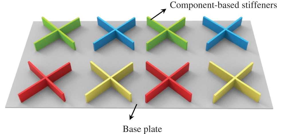
Figure 1: A typical stiffened plate structure constructed by some structural components

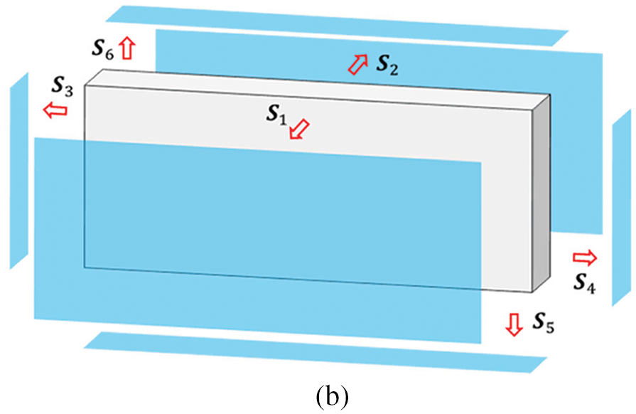
Figure 2: The geometry description of a stiffener component with the straight skeleton: (a) Geometric model of the straight stiffener (b) The outer boundaries of the straight stiffener
For a curved component with constant thickness as shown in Fig. 3, we can use a quadratic Bezier equation to define the coordinates of an arbitrary point on the curved skeleton
where
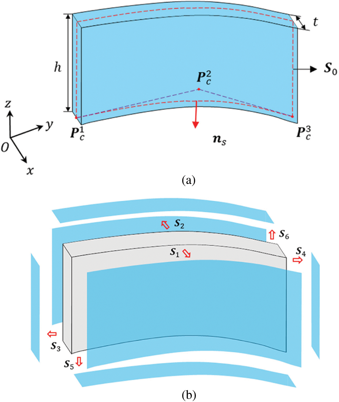
Figure 3: The geometry description of a stiffener component with the curved skeleton: (a) Geometric model of the curved stiffener (b) The outer boundaries of the curved stiffener
Based on Eqs. (2) and (4), the profile of the outer boundaries of a component-based stiffener can be described in the following way:
where
In the MMC-based topology optimization approach, although the boundary of a single thin-walled component is smooth, the boundary of the region occupied by multiple overlapped components may not be smooth any more. This issue can be alleviated in the Eulerian description and fixed 2D/3D FE mesh-based MMC approach by introducing the so-called ersatz material model [52], where the equivalent stiffness of an element is determined by the values of the global topology description function on its four nodes. In the present work, since Lagrangian description is used for representing the geometry of a component as well as the layout of the structure, it is quite important to avoid the intersection of components during the process of optimization. Besides, the intersection or overlap of these stiffeners is also generally to be avoided in the design process of stiffened plate structures. In the present work, to prevent the stiffeners from intersecting with each other during the optimization process, the component-connection mechanism based on a so-called adaptive ground structure method is employed [53]. As illustrated in Fig. 4, a ground structure is composed of the base plate and component-based stiffeners, where the stiffeners are connected to each other by a series of driven nodes and the entire structure is updated iteratively by moving a series of driven nodes and varying some size parameters of the components. Correspondingly, the optimal shape and size of the stiffeners can be obtained by optimizing the coordinates of these movable nodes and other control points of the skeletons (

Figure 4: A schematic illustration of the node-driven adaptive ground structure method
2.2 Minimum Thickness Control of Stiffeners
In practical applications, constraining feature sizes of the structural members is very meaningful to improving the design manufacturability [54]. This, fortunately, can be easily achieved in the explicit optimization framework by directly setting bound limits on relevant geometry parameters. In the present work, benefiting from the explicit geometric description of the stiffeners, it is also easy to control the sizes of stiffeners, such as the height h and the length l
In the present work, for a stiffener optimization problem with feature size constraint
where
where

Figure 5: The stiffener thickness penalization by the Heaviside function
2.3 Numerical Analysis Model of Stiffened Plate Structures Based on the MMC Method
In the present work, classical stress/displacement shell elements with three or four nodes constructed from a refined shell theory [55] are adopted for structural response analysis. As the geometry of the stiffened plate is described explicitly in a pure Lagrangian way, a clean and clear geometry model with smooth boundaries can be generated; therefore, it is quite convenient to discretize both the base plate and the stiffeners into an adaptive body-fitted mesh through the adaptive re-meshing technique (see Fig. 6 for reference). Compared with the 3D solid or equivalent stiffness model with a fixed finite element (FE) mesh commonly used in previous works, the shell-element-based numerical analysis model adopted in the present work has a relatively low computational cost and is undoubtedly more suitable for the simulation of stiffened plate structures. Furthermore, since the FE model is built on exact geometry and a refined local FE mesh can be constructed in the regions of special interest (e.g., along the boundary of inner holes and the interfaces between the stiffeners and the base plate, see Fig. 28a for reference), more accurate analysis results can be obtained at each iteration step of optimization.

Figure 6: A schematic illustration of the numerical analysis model of a stiffened plate structure
3 Problem Formulation and Sensitivity Analysis
Based on the above discussions, it can be concluded that the design variables of a stiffened plate structure topology optimization problem in the proposed MMC-based framework can be summarized as
With the above result bearing in mind, the optimal design problem for stiffened plate structures can be formulated as
where I is the objective function,
In the present study, with the purpose of enhancing the global stiffness of the stiffened plate structures, the considered optimization problem is to minimize the structural compliance under the available volume constraint and the corresponding problem formulation can be formulated as
S.t.
where
The proposed solution framework is essentially based on the explicit boundary evolution, and therefore shape sensitivity analysis approach can be performed to obtain the sensitivities of an objective or constraint functional for numerical optimization. According to [56,57], the shape sensitivity of a general objective/constraint functional can be written as a volume integral
where
Actually, for a typical component shown in Figs. 2 and 3, only the contributions of outer boundary
In Eq. (11), the outward normal velocity field
where
3.2.1 Sensitivity Analysis of the Straight Component
For a typical cuboid component with a straight skeleton as shown in Fig. 2, taking the boundary
and
where
Accordingly, the normal velocity field along
In Eq. (16), the normal outward vector
Therefore, we have
Based on the above results, the normal velocity field along
Similarly, the normal velocity field along
Based on the above equations, the variation of I with respect to the
where the expressions of
where
3.2.2 Sensitivity Analysis of the Curved Component
For a curved component as shown in Fig. 3, the variation of the mid-surface
The tangential vector
Accordingly, we have
Based on the above equations, it yields that the normal velocity field along
Similarly,
Finally, we have
where the expressions of
In this section, four numerical examples, including straight and curved stiffeners, hierarchical stiffeners, and a stiffened plate with a cutout, are tested to validate the effectiveness of the proposed approach. Without loss of generality, all involved quantities are assumed to be dimensionless. The Young’s modulus of the base plate and the stiffeners are set as
4.1 A Plate Example with Straight Stiffeners
In the first example, the optimization problem of a stiffened plate structure with straight stiffeners is tested. The corresponding problem setting is shown in Fig. 7. The height of all stiffeners is set as

Figure 7: The problem setting of the plate example with straight stiffeners

Figure 8: Three different initial designs of the plate example with straight stiffeners: (a) 315 components (b) 450 components (c) 609 components
The corresponding optimized results obtained from the different initial layouts with compliance values of 305.40, 303.84 and 303.06, respectively, are displayed in Fig. 9 (note that those narrow components with a thickness less than the threshold

Figure 9: The optimized results of the plate example with straight stiffeners obtained from different initial designs: (a)
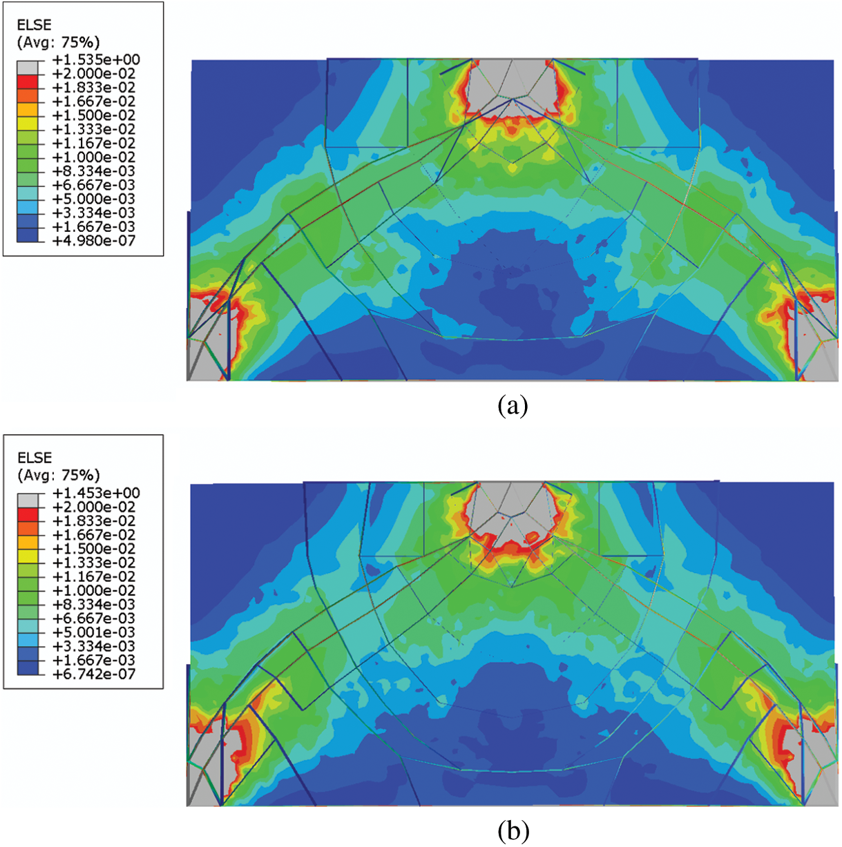
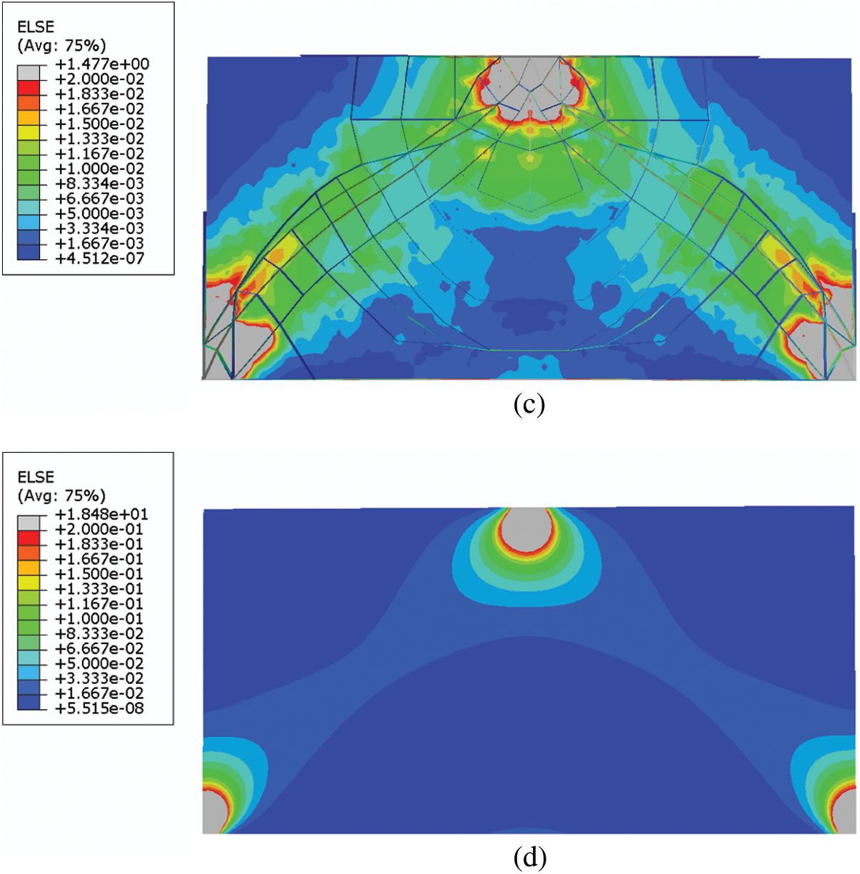
Figure 10: The strain energy distributions of the plate example with straight stiffeners: (a) Optimized design (315 components) (b) Optimized design (450 components) (c) Optimized design (609 components) (d) Base panel

Figure 11: Iteration histories of the objective and constraint values of the three cases of the plate example with straight stiffeners: (a) 315 components (b) 450 components (c) 609 components
Next, to examine the validity of the proposed penalization mechanism in addressing minimum thickness control of stiffeners, the lower bound
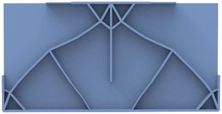
Figure 12: The optimized result with the stiffener thickness penalization mechanism of the plate example with straight stiffeners (

4.2 A Plate Example with Curved Stiffeners
In this example, the curved stiffener optimization problem is considered. The problem setting of this example is shown in Fig. 13. The thickness of the base panel is

Figure 13: The problem setting of the plate example with curved stiffeners

Figure 14: The initial design of the plate example with curved stiffeners
Fig. 15 depicts the final optimized result and the corresponding iteration history for the optimization process is shown in Fig. 16. As can be seen from the optimized result, some curved stiffeners appear in the optimized structure and form several strong structural members to transfer the point load. Some intermediate designs in the optimization process are presented in Fig. 17, which shows the shape and size evolutions of curved stiffeners during the optimization iterations. In the proposed optimization framework, since the profile of the curved stiffeners is described explicitly through a series of geometry parameters, the optimized design can be directly imported into CAD systems, as shown in Fig. 18.

Figure 15: The optimized result of the plate example with curved stiffeners (

Figure 16: Iteration history of the objective and constraint values of the plate example with curved stiffeners

Figure 17: Some intermediate designs of the plate example with curved stiffeners

Figure 18: The CAD model of the optimized structure of the plate example with curved stiffeners
4.3 A Hierarchical Stiffened Plate Example
Hierarchical stiffened configuration, as an advanced design form, is widely used in large industrial equipment. In this subsection, we try to apply the proposed method to the optimization design of a hierarchical stiffened structure. The problem setting of the considered hierarchical stiffened plate example is shown in Fig. 19. The thickness of the base plate is

Figure 19: The problem setting of the hierarchical stiffened plate example
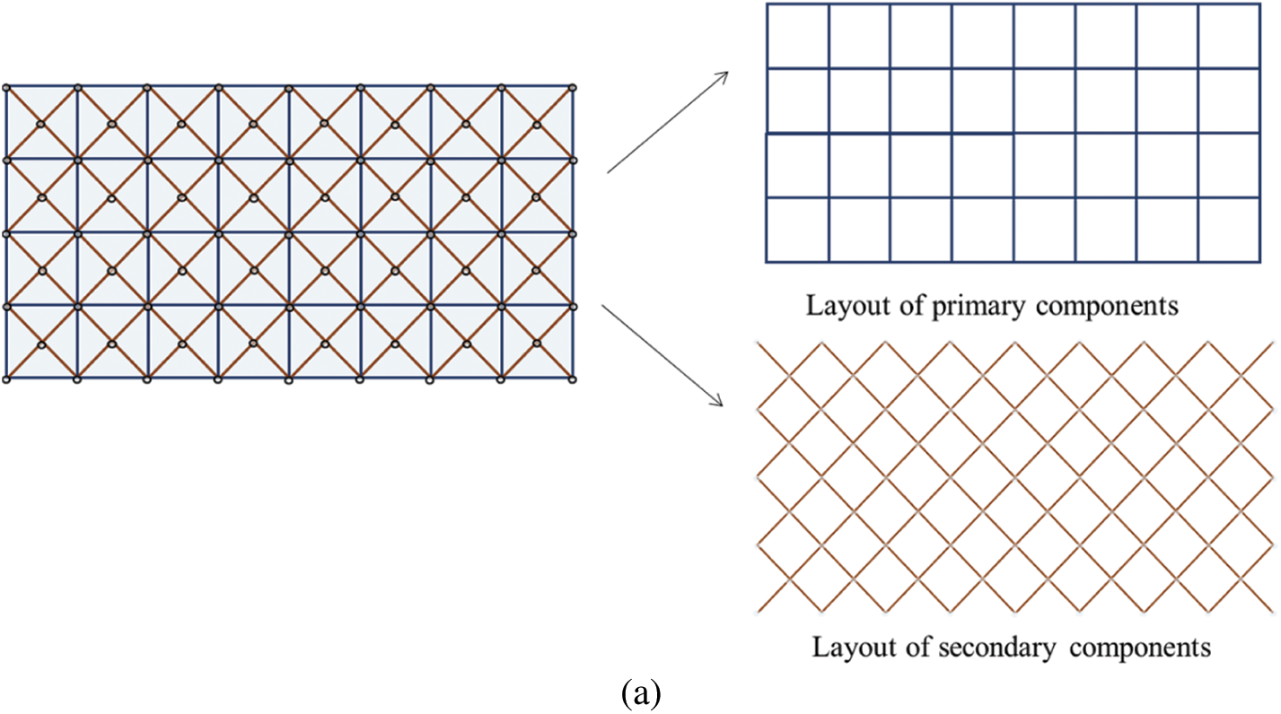
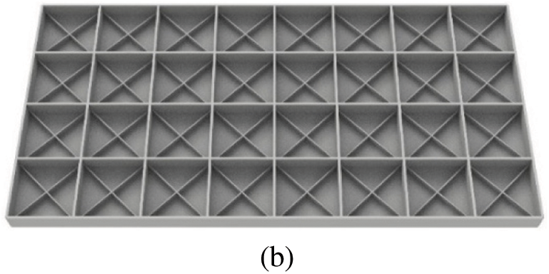
Figure 20: The initial design of the hierarchical stiffened plate example: (a) A top view (b) An overall view
The final optimized hierarchical stiffened plate with a compliance value of 123.14 is shown in Fig. 21. As can be seen from the figure, several main force transmission paths composed of the primary stiffeners are generated to effectively resist the in-plane bending moment and tensile forces. Meanwhile, the cross-distributed secondary stiffeners in the plate can well resist shear deformation. In addition, by arranging the primary stiffeners and secondary stiffeners, both the global and local stiffness of the plate structure can be enhanced greatly from a mechanical point of view. Fig. 22 shows the iteration history for the optimization process of this example and the corresponding CAD model of the optimized structure is shown in Fig. 23.

Figure 21: The optimized result of the hierarchical stiffened plate example (

Figure 22: Iteration history of the objective and constraint values of the hierarchical stiffened plate example

Figure 23: The CAD model of the optimized structure of the hierarchical stiffened plate example
4.4 A Rectangular Stiffened Plate with an Inner Hole Example
In the last example, the stiffener optimization problem of a rectangular plate with an inner hole is considered and the relevant geometry data, boundary conditions and external loads are shown in Fig. 24. The thickness of the base panel is

Figure 24: The problem setting of the rectangular stiffened plate with an inner hole example

Figure 25: The initial design of the rectangular stiffened plate with an inner hole example: (a) A top view (b) An overall view
The corresponding optimized result with structural compliance of

Figure 26: The optimized result of the rectangular stiffened plate with an inner hole example (

Figure 27: The strain energy distribution in the optimized design of the rectangular stiffened plate with an inner hole example

Figure 28: Locally refined mesh and the stress distribution in the optimized design of the rectangular stiffened plate with an inner hole example: (a) Locally refined mesh along the boundary of the hole (b) The stress distribution in the optimized design

Figure 29: Iteration history of the objective and constraint values of the rectangular stiffened plate with an inner hole example

Figure 30: The CAD model of the optimized structure of the rectangular stiffened plate with an inner hole example
In this study, a novel approach based on the MMC solution framework for topology optimization of stiffened plate structures is proposed. In this method, all the stiffeners are treated as a set of structural components and the optimal design of stiffened plate structures can be obtained by optimizing the explicit geometry parameters of these components. By adopting Lagrangian type description for geometry representation, an adaptive ground structure method is utilized to regularize the optimization process, while dynamically updated shell elements obtained from an adaptive re-meshing technique are adopted for structural response analysis. Under this treatment, not only highly accurate analysis results with relatively low computational efforts can be achieved, but also a clear and clean optimized stiffened structure without extra processing can be obtained. Compared with previous methods, the proposed method has a smaller number of design variables and can accomplish feature size control of the stiffeners easily. Furthermore, various types of stiffened plate structures optimization problems, including straight and curved stiffeners, hierarchical stiffeners, and stiffened plates with cutouts, can be solved uniformly in the proposed explicit topology optimization framework, and numerical examples demonstrate the effectiveness and efficiency of the proposed approach. Last but not least, the generated optimized structures can be seamlessly transferred to CAD/CAE systems, which has a great prospect in industrial applications. As a preliminary attempt, only the minimum compliance optimization problem is considered in the present work and it can be expected that the proposed method has the potential to be applied to other stiffener optimization designs considering complex multi-physics fields, such as acoustic, thermal, etc. Another promising investigation direction is to extend the present work to the stiffener optimization of arbitrary surfaces. Corresponding research results will be reported elsewhere.
Funding Statement: This work is supported by the National Key Research and Development Plan (2020YFB1709401), the National Natural Science Foundation (11821202, 11732004, 12002077, 12002073), the Fundamental Research Funds for Central Universities (DUT21RC(3)076, DUT20RC(3)020), Doctoral Scientific Research Foundation of Liaoning Province (2021-BS-063) and 111 Project (B14013).
Conflicts of Interest: The authors declare that they have no conflicts of interest to report regarding the present study.
References
1. Wang, L., Basu, P. K., Leiva, J. P. (2004). Automobile body reinforcement by finite element optimization. Finite Elements in Analysis and Design, 40(8), 879–893. DOI 10.1016/S0168-874X(03)00118-5. [Google Scholar] [CrossRef]
2. Loughlan, J. (2018). Thin-walled structures: Advances in research, design and manufacturing technology. USA: CRC Press. [Google Scholar]
3. Noor, A. K. (1973). Free vibrations of multilayered composite plates. AIAA Journal, 11(7), 1038–1039. DOI 10.2514/3.6868. [Google Scholar] [CrossRef]
4. Qatu, M. S., Sullivan, R. W., Wang, W. (2010). Recent research advances on the dynamic analysis of composite shells: 2000–2009. Composite Structures, 93(1), 14–31. DOI 10.1016/j.compstruct.2010.05.014. [Google Scholar] [CrossRef]
5. Viola, E., Tornabene, F., Fantuzzi, N. (2013). General higher-order shear deformation theories for the free vibration analysis of completely doubly-curved laminated shells and panels. Composite Structures, 95, 639–666. DOI 10.1016/j.compstruct.2012.08.005. [Google Scholar] [CrossRef]
6. Shroff, S., Acar, E., Kassapoglou, C. (2017). Design, analysis, fabrication, and testing of composite grid-stiffened panels for aircraft structures. Thin-Walled Structures, 119, 235–246. DOI 10.1016/j.tws.2017.06.006. [Google Scholar] [CrossRef]
7. Bendsøe, M. P., Kikuchi, N. (1988). Generating optimal topologies in structural design using a homogenization method. Computer Methods in Applied Mechanics and Engineering, 71(2), 197–224. DOI 10.1016/0045-7825(88)90086-2. [Google Scholar] [CrossRef]
8. Bendsøe, M. P. (1989). Optimal shape design as a material distribution problem. Structural Optimization, 1(4), 193–202. DOI 10.1007/BF01650949. [Google Scholar] [CrossRef]
9. Zhou, M., Rozvany, G. (1991). The COC algorithm, part II: Topological, geometrical and generalized shape optimization. Computer Methods in Applied Mechanics and Engineering, 89(1–3), 309–336. DOI 10.1016/0045-7825(91)90046-9. [Google Scholar] [CrossRef]
10. Wang, M. Y., Wang, X. M., Guo, D. M. (2003). A level set method for structural topology optimization. Computer Methods in Applied Mechanics and Engineering, 192(1–2), 227–246. DOI 10.1016/S0045-7825(02)00559-5. [Google Scholar] [CrossRef]
11. Honda, M., Kawamura, C., Kizaki, I., Miyajima, Y., Takezawa, A. et al. (2021). Construction of design guidelines for optimal automotive frame shape based on statistical approach and mechanical analysis. Computer Modeling in Engineering & Sciences, 128(2), 731–742. DOI 10.32604/cmes.2021.016181. [Google Scholar] [CrossRef]
12. Yan, J., Sui, Q. Q., Fan, Z. R., Duan, Z. Y. (2022). Multi-material and multiscale topology design optimization of thermoelastic lattice structures. Computer Modeling in Engineering & Sciences, 130(2), 967–986. DOI 10.32604/cmes.2022.017708. [Google Scholar] [CrossRef]
13. Zou, J., Mou, H. L. (2022). Topology optimization of self-supporting structures for additive manufacturing with adaptive explicit continuous constraint. Computer Modeling in Engineering & Sciences, 131(1), 1–19. DOI 10.32604/cmes.2022.020111. [Google Scholar] [CrossRef]
14. Lagaros, N. D., Fragiadakis, M., Papadrakakis, M. (2004). Optimum design of shell structures with stiffening beams. AIAA Journal, 42(1), 175–184. DOI 10.2514/1.9041. [Google Scholar] [CrossRef]
15. Wu, B. C., Young, G. S., Huang, T. Y. (2000). Application of a two-level optimization process to conceptual structural design of a machine tool. International Journal of Machine Tools and Manufacture, 40(6), 783–794. DOI 10.1016/S0890-6955(99)00113-3. [Google Scholar] [CrossRef]
16. Higgins, P. J., Wegner, P., Viisoreanu, A., Sanford, G. (2004). Design and testing of the minotaur advanced grid-stiffened fairing. Composite Structures, 66(1–4), 339–349. DOI 10.1016/j.compstruct.2004.04.055. [Google Scholar] [CrossRef]
17. Gosowski, B. (2007). Non-uniform torsion of stiffened open thin-walled members of steel structures. Journal of Constructional Steel Research, 63(6), 849–865. DOI 10.1016/j.jcsr.2006.02.006. [Google Scholar] [CrossRef]
18. Jármai, K., Farkas, J. (2001). Optimum cost design of welded box beams with longitudinal stiffeners using advanced backtrack method. Structural and Multidisciplinary Optimization, 21(1), 52–59. DOI 10.1007/s001580050167. [Google Scholar] [CrossRef]
19. Pavlovčič, L., Detzel, A., Kuhlmann, U., Beg, D. (2007). Shear resistance of longitudinally stiffened panels—Part 1: Tests and numerical analysis of imperfections. Journal of Constructional Steel Research, 63(3), 337–350. DOI 10.1016/j.jcsr.2006.05.008. [Google Scholar] [CrossRef]
20. Pavlovčič, L., Beg, D., Kuhlmann, U. (2007). Shear resistance of longitudinally stiffened panels—Part 2: Numerical parametric study. Journal of Constructional Steel Research, 63(3), 351–364. DOI 10.1016/j.jcsr.2006.05.009. [Google Scholar] [CrossRef]
21. Kapania, R., Li, J., Kapoor, H. (2005). Optimal design of unitized panels with curvilinear stiffeners. Proceedings of the AIAA 5th ATIO and 16th Lighter-than-Air Sys Tech. and Balloon Systems Conferences, pp. 7482–7511. Virginia. [Google Scholar]
22. Mulani, S. B., Slemp, W. C., Kapania, R. (2010). EBF3PanelOpt: A framework for curvilinear stiffened panels optimization under multiple load cases. Proceedings of the 13th AIAA/ISSMO Multidisciplinary Analysis Optimization Conference, pp. 9238–9254. Texas. [Google Scholar]
23. Mulani, S. B., Slemp, W. C. H., Kapania, R. K. (2013). EBF3PanelOpt: An optimization framework for curvilinear blade-stiffened panels. Thin-Walled Structures, 63, 13–26. DOI 10.1016/j.tws.2012.09.008. [Google Scholar] [CrossRef]
24. Wang, B., Hao, P., Li, G., Tian, K., Du, K. F. et al. (2014). Two-stage size-layout optimization of axially compressed stiffened panels. Structural and Multidisciplinary Optimization, 50(2), 313–327. DOI 10.1007/s00158-014-1046-6. [Google Scholar] [CrossRef]
25. Hao, P., Wang, B., Tian, K., Li, G., Du, K. F. et al. (2016). Efficient optimization of cylindrical stiffened shells with reinforced cutouts by curvilinear stiffeners. AIAA Journal, 54(4), 1350–1363. DOI 10.2514/1.J054445. [Google Scholar] [CrossRef]
26. Liu, Y., Shimoda, M. (2015). Non-parametric shape optimization method for natural vibration design of stiffened shells. Computers & Structures, 146, 20–31. DOI 10.1016/j.compstruc.2014.08.003. [Google Scholar] [CrossRef]
27. Liu, Y., Shimoda, M. (2013). Parameter-free optimum design method of stiffeners on thin-walled structures. Structural and Multidisciplinary Optimization, 49(1), 39–47. DOI 10.1007/s00158-013-0954-1. [Google Scholar] [CrossRef]
28. Wang, D., Abdalla, M. M., Wang, Z. P., Su, Z. (2019). Streamline stiffener path optimization (SSPO) for embedded stiffener layout design of non-uniform curved grid-stiffened composite (NCGC) structures. Computer Methods in Applied Mechanics and Engineering, 344, 1021–1050. DOI 10.1016/j.cma.2018.09.013. [Google Scholar] [CrossRef]
29. Wang, D., Abdalla, M. M., Zhang, W. H. (2018). Sensitivity analysis for optimization design of non-uniform curved grid-stiffened composite (NCGC) structures. Composite Structures, 193, 224–236. DOI 10.1016/j.compstruct.2018.03.077. [Google Scholar] [CrossRef]
30. Lam, Y. C., Santhikumar, S. (2003). Automated rib location and optimization for plate structures. Structural and Multidisciplinary Optimization, 25(1), 35–45. DOI 10.1007/s00158-002-0270-7. [Google Scholar] [CrossRef]
31. Ansola, R., Canales, J., Tarrago, J. A., Rasmussen, J. (2004). Combined shape and reinforcement layout optimization of shell structures. Structural and Multidisciplinary Optimization, 27(4), 219–227. DOI 10.1007/s00158-004-0399-7. [Google Scholar] [CrossRef]
32. Afonso, S. M. B., Sienz, J., Belblidia, F. (2005). Structural optimization strategies for simple and integrally stiffened plates and shells. Engineering Computations, 22(4), 429–452. DOI 10.1108/02644400510598769. [Google Scholar] [CrossRef]
33. Ma, X. T., Wang, F. Y., Aage, N., Tian, K., Hao, P. et al. (2021). Generative design of stiffened plates based on homogenization method. Structural and Multidisciplinary Optimization, 64, 3951–3969. DOI 10.1007/s00158-021-03070-3. [Google Scholar] [CrossRef]
34. Aage, N., Andreassen, E., Lazarov, B. S., Sigmund, O. (2017). Giga-voxel computational morphogenesis for structural design. Nature, 550(7674), 84–86. DOI 10.1038/nature23911. [Google Scholar] [CrossRef]
35. Zhang, W. H., Zhao, L. Y., Gao, T., Cai, S. Y. (2017). Topology optimization with closed B-splines and Boolean operations. Computer Methods in Applied Mechanics and Engineering, 315, 652–670. DOI 10.1016/j.cma.2016.11.015. [Google Scholar] [CrossRef]
36. Feng, S. Q., Zhang, W. H., Meng, L., Xu, Z., Chen, L. (2021). Stiffener layout optimization of shell structures with B-spline parameterization method. Structural and Multidisciplinary Optimization, 63(6), 2637–2651. DOI 10.1007/s00158-021-02873-8. [Google Scholar] [CrossRef]
37. Bakker, C., Zhang, L., Higginson, K., Keulen, F. V. (2021). Simultaneous optimization of topology and layout of modular stiffeners on shells and plates. Structural and Multidisciplinary Optimization, 64(5), 3147–3161. DOI 10.1007/s00158-021-03081-0. [Google Scholar] [CrossRef]
38. Chu, S., Townsend, S., Featherston, C., Kim, H. A. (2021). Simultaneous layout and topology optimization of curved stiffened panels. AIAA Journal, 59(7), 2768–2783. DOI 10.2514/1.J060015. [Google Scholar] [CrossRef]
39. Li, Q. H., Qu, Y. X., Luo, Y. F., Liu, S. T. (2021). Concurrent topology optimization design of stiffener layout and cross-section for thin-walled structures. Acta Mechanica Sinica, 37(3), 472–481. DOI 10.1007/s10409-020-01034-2. [Google Scholar] [CrossRef]
40. Qin, X. C., Dong, C. Y. (2021). NURBS-based isogeometric shape and material optimization of curvilinearly stiffened plates with FGMs. Thin-Walled Structures, 162, 107601. DOI 10.1016/j.tws.2021.107601. [Google Scholar] [CrossRef]
41. Singh, K., Kapania, R. K. (2021). Accelerated optimization of curvilinearly stiffened panels using deep learning. Thin-Walled Structures, 161, 107418. DOI 10.1016/j.tws.2020.107418. [Google Scholar] [CrossRef]
42. Xu, K., Li, T., Guan, G. F., Qu, J. L., Zhao, Z. et al. (2022). Optimization design of an embedded multi-cell thin-walled energy absorption structures with local surface nanocrystallization. Computer Modeling in Engineering & Sciences, 130(2), 987–1002. DOI 10.32604/cmes.2022.018128. [Google Scholar] [CrossRef]
43. Mattheck, C., Burkhardt, S. (1990). A new method of structural shape optimization based on biological growth. International Journal of Fatigue, 12(3), 185–190. DOI 10.1016/0142-1123(90)90094-U. [Google Scholar] [CrossRef]
44. Ding, X. H., Yamazaki, K. (2004). Stiffener layout design for plate structures by growing and branching tree model (application to vibration-proof design). Structural and Multidisciplinary Optimization, 26(1–2), 99–110. DOI 10.1007/s00158-003-0309-4. [Google Scholar] [CrossRef]
45. Ji, J., Ding, X. H., Xiong, M. (2014). Optimal stiffener layout of plate/shell structures by bionic growth method. Computers & Structures, 135, 88–99. DOI 10.1016/j.compstruc.2014.01.022. [Google Scholar] [CrossRef]
46. Li, B. T., Hong, J., Liu, Z. F. (2014). Stiffness design of machine tool structures by a biologically inspired topology optimization method. International Journal of Machine Tools and Manufacture, 84, 33–44. DOI 10.1016/j.ijmachtools.2014.03.005. [Google Scholar] [CrossRef]
47. Li, B. T., Xuan, C. B., Tang, W. H., Zhu, Y. S., Yan, K. (2018). Topology optimization of plate/shell structures with respect to eigenfrequencies using a biologically inspired algorithm. Engineering Optimization, 51(11), 1829–1844. DOI 10.1080/0305215X.2018.1552952. [Google Scholar] [CrossRef]
48. Li, B. T., Huang, C. J., Xuan, C. B., Liu, X. (2019). Dynamic stiffness design of plate/shell structures using explicit topology optimization. Thin-Walled Structures, 140, 542–564. DOI 10.1016/j.tws.2019.03.053. [Google Scholar] [CrossRef]
49. Dong, X. H., Ding, X. H., Li, G. J., Lewis, G. P. (2019). Stiffener layout optimization of plate and shell structures for buckling problem by adaptive growth method. Structural and Multidisciplinary Optimization, 61, 301–318. DOI 10.1007/s00158-019-02361-0. [Google Scholar] [CrossRef]
50. Guo, X., Zhang, W. S., Zhong, W. L. (2014). Doing topology optimization explicitly and geometrically—A new moving morphable components based framework. Journal of Applied Mechanics, 81(8), 081009. DOI 10.1115/1.4027609. [Google Scholar] [CrossRef]
51. Zhang, W. S., Zhang, J., Guo, X. (2016). Lagrangian description based topology optimization—A revival of shape optimization. Journal of Applied Mechanics, 83(4), 041010. DOI 10.1115/1.4032432. [Google Scholar] [CrossRef]
52. Zhang, W. S., Yuan, J., Zhang, J., Guo, X. (2015). A new topology optimization approach based on moving morphable components (MMC) and the ersatz material model. Structural and Multidisciplinary Optimization, 53(6), 1243–1260. DOI 10.1007/s00158-015-1372-3. [Google Scholar] [CrossRef]
53. Miao, Y. H. (2021). Topology optimization of multiphase material structure based on joint connection (Master Thesis). Dalian University of Technology, China. [Google Scholar]
54. Lazarov, B. S., Wang, F. W. (2017). Maximum length scale in density based topology optimization. Computer Methods in Applied Mechanics and Engineering, 318, 826–844. DOI 10.1016/j.cma.2017.02.018. [Google Scholar] [CrossRef]
55. Chapelle, D., Bathe, K. J. (2010). The finite element analysis of shells-fundamentals. USA: Springer Science & Business Media. [Google Scholar]
56. Laporte, E., Le Tallec, P. (2002). Numerical methods in sensitivity analysis and shape optimization. USA: Springer Science & Business Media. [Google Scholar]
57. Komkov, V., Choi, K. K., Haug, E. J. (1986). Design sensitivity analysis of structural systems. USA: Academic Press. [Google Scholar]
58. Svanberg, K. (1987). The method of moving asymptotes—A new method for structural optimization. International Journal for Numerical Methods in Engineering, 24(2), 359–373. DOI 10.1002/(ISSN)1097-0207. [Google Scholar] [CrossRef]
Appendix A. Some terms in the expressions of sensitivity analysis
Cite This Article
 Copyright © 2023 The Author(s). Published by Tech Science Press.
This work is licensed under a Creative Commons Attribution 4.0 International License , which permits unrestricted use, distribution, and reproduction in any medium, provided the original work is properly cited.
 Downloads
 Citation Tools