
 Submit a Paper
 Propose a Special lssue
 Open Access
ARTICLE

Intelligent Sensing and Control of Road Construction Robot Scenes Based on Road Construction
School of Instrument Science and Engineering, Southeast University, Nanjing, 210096, China
* Corresponding Author: Weigong Zhang. Email:
Structural Durability & Health Monitoring 2024, 18(2), 111-124. https://doi.org/10.32604/sdhm.2023.043563
Received 06 July 2023; Accepted 18 September 2023; Issue published 22 March 2024
 View Full Text
 Download PDF
Abstract
Automatic control technology is the basis of road robot improvement, according to the characteristics of construction equipment and functions, the research will be input type perception from positioning acquisition, real-world monitoring, the process will use RTK-GNSS positional perception technology, by projecting the left side of the earth from Gauss-Krueger projection method, and then carry out the Cartesian conversion based on the characteristics of drawing; steering control system is the core of the electric drive unmanned module, on the basis of the analysis of the composition of the steering system of unmanned engineering vehicles, the steering system key components such as direction, torque sensor, drive motor and other models are established, the joint simulation model of unmanned engineering vehicles is established, the steering controller is designed using the PID method, the simulation results show that the control method can meet the construction path demand for automatic steering. The path planning will first formulate the construction area with preset values and realize the steering angle correction during driving by PID algorithm, and never realize the construction-based path planning, and the results show that the method can control the straight path within the error of 10 cm and the curve error within 20 cm. With the collaboration of various modules, the automatic construction simulation results of this robot show that the design path and control method is effective.Keywords
With the development of engineering technology, vehicle operation tends to be automatic. However, at present, construction vehicles are still mainly operated by hand, and there are some problems in manpower, such as work efficiency needs to be improved, high employment cost and harsh working environment. Therefore, unmanned driving has become a necessary technology in project operations [1]. In the research on unmanned driving of construction vehicles, steering control, scene perception, and path planning are the three key technologies [2]. This study integrates machine intelligence technology to upgrade the equipment [3]. The upgraded equipment has the ability of autonomous operation, which can meet the growing construction demand [4]. However, this process is accomplished with the cooperation of various modules, of which scene perception, remote control implementation, and path planning are the main parts. In conventional automatic driving, there are some problems, such as blurred visual angle of scene perception and difficult positioning of remote driving. And in order to separately engineer these problems, the study will be designed while maintaining the construction parameters, adding advanced positioning technology and unmanned autopilot technology to the design, and transforming the road construction robot through modular settings to finally meet the construction needs and provide road construction as well as civil engineering to provide new ideas. The practical contribution of this research is to provide an optimization method of automatic driving in engineering construction by improving the positioning module and adjusting the parameters. The purpose is to use automation equipment instead of manpower to protect the safety of construction personnel.
Namazi et al. used intelligent perception systems for traffic management, solving the vehicle localization problem through deep learning and image processing methods to achieve coordinate estimation in the presence of mounted cameras, and demonstrated the dynamic perception of vehicles through real data measurements [5]. Guindel et al. also used scenario-aware technology for transportation, building a deep learning framework to simulate traffic scenarios, and the results demonstrated that the perception system can cope with various scenarios and provide an effective basis for traffic decisions [6]. Xia’s experimental team used scenario-aware technology for carbon emission optimization in the energy industry, where grid state information was The results of the deep perception provide reference for grid load demand to optimize the flexibility and control of the grid, and the simulation results of the linear system prove the effectiveness of the method [7]. Fu et al. optimized the scene perception technique itself, and in order to reduce the influence of distractors such as smoke on the scene perception, deblurring was achieved through the mathematical inversion of the atmospheric scattering model [8], combining optical and Soni et al. considered text detection and localization to be important in scene perception, for which they proposed a new text perception model and detection method, and established an algorithm that removes mixed pixels from the edges of blurred images to distinguish associated characters, and the results of data simulation of natural scenes showed that the method achieved optimization of results such as accuracy and recall [9]. Scholars such as Fu et al. assembled scene perception by augmented reality and optimized automatically triggered commands by understanding the context to reduce the cognitive load on the operator, and the results showed that their proposed method improved the performance of the assembly and reduced errors [10].
The development of technology applications in road construction is also very broad, and various aspects of road construction have been optimized to some extent with the improvement of the level of intelligent control technology and sensor technology. In terms of cost control, the scarcity of natural resources in Skp A and Gb B has a great impact on pavement construction, and they first assessed the feasibility of pavement material optimization schemes as a basis for aggregate replacement, and in order to get the best mixing ratio, they conducted experiments on various ratios of optimization schemes, and the results proved that a certain percentage of recycled asphalt pavement materials have good performance [11]. Sung and other scholars believe that Drone technology has made significant progress and has a wide range of applications in various fields, but it has failed to be involved in road construction, so they investigated the use of drones in Korean road construction and made recommendations on the use of drones at construction sites to promote the application of drone technology in civil engineering and construction [12]. Jung et al. used a variety of visual techniques with three-dimensional technology to assess road roughness and construct the road surface in three dimensions through UAV photography and LIDAR, their results show that LIDAR performance is close to the real situation, while they believe that the accuracy of related measurements will improve with the growth of UAV technology [13]. Gebretekle’s experimental team used digital technology in project management of road construction, they proposed a framework that can support decision makers in construction organizations, which integrates fuzzy mathematics and linguistic assessment to quantify the assessment of experts for subsequent construction management [14]. Kavitha et al. studied pavement landslides during road construction, they used remote sensing and GIS to plan landslide prone areas, the process starts with the determination of visible physical and chemical properties of the pavement. The factors were then assigned weights and integrated through data techniques to obtain the susceptible zone rating, and the results were validated by simulations of the actual data collected, which showed that the method is suitable for landslide hazard mapping and planning [15].
In the driving of automatic construction equipment, the scene perception technology of the existing model is still insufficient, and the positioning problem of the equipment also urgently needs to be solved. Scene perception technology has been widely used in various fields, and scholars are optimizing the technology itself. There is sufficient space for the application of scene perception in the road construction process, which not only can avoid the danger and complexity of manual work, but also the intelligent data analysis results have the advantage of accuracy unmatched by manual decision making. Therefore, the application of scene perception technology to road construction is of positive significance to cost control and construction requirements. The study will design and optimize road construction robots to support road construction according to the actual situation of road construction.
3 Scene Perception Realization Path and Control Design of Road Construction Robot
3.1 Scene Perception-Based Control Scheme for Construction Robots
In addition to having key control technologies, construction robots replacing manual labor also need to drive in real scenarios. Despite the technological breakthroughs in driving, most of them are based on a single driving task, and they still need to be planned to fit the construction needs in construction scenarios. The research will upgrade and modify the existing pavement construction equipment to include various modules for automatic control, and for this purpose, the compacting road roller will be selected as the basis for the automatic robot. The original roller setup has a good design for engineering applications, so the upgrade focuses on realistic perception and decision control, reducing changes to its own construction modules. Designed according to the division of labor, the control scheme for scene perception consists of real-world measurement and remote management, where the main purpose of real-world measurement is to obtain the location information of the construction robot as well as the road condition information. The positioning system will use PTK combined with GNSS to obtain high-precision positioning. In the process of PTK positioning, a positioning base station will be used to differentially process the position information received from the base station and the phase information of the satellite signal to obtain more accurate positioning information. The position of a single GNSS antenna is obtained by linking more than four groups of satellite signals. The accuracy of positioning base station is generally higher than that of the mobile base station, and the accuracy of positioning can be improved by eliminating the interference of the signal from the atmosphere. The two high-precision positioning settings make the differential computing performance improved and the operation speed accelerated to meet the positioning requirements.
The automated robot will make decisions when the live measurement signal completes processing, and the operational implementation of this process will rely on a remote control solution. The overall logic of the control module is to connect the operator’s control device to the wireless network at the construction site [16]. The signal commands from the control device will be relayed through the industrial router, and if the distance is too long the router will be added to bridge the signal. When the construction robot receives the signal, it will be converted and processed, and the command will be sent to the sub-controller through the bus, and then the whole vehicle will be finally controlled through a parsing process. The network equipment of remote control needs to consider the environmental factors of road construction interference and should choose the equipment model suitable for the industrial environment, and the bridging routers need to be evenly distributed to ensure the signal quality. The signal conversion process for the industrial robot will establish a serial transmission for fast access, so a serial device with a specific protocol format will be selected as the signal conversion hardware solution. The control device that provides decision making and emits control will be selected as a touchable tablet computer with sufficient performance [17]. The communication protocol of this module is the network basis for ensuring accurate and reliable hardware sending and receiving signals. The study will use hexadecimal bytes to design the communication protocol data string format by bit, and the test signal for smooth serial communication will be used as the data header as a partition to detect the status, and the subsequent bytes will be arranged according to the functional partition. The partition corresponding to each byte signal will single map the functional area of the construction robot, and this design will classify the signals into whole vehicle control signals, braking, construction, and emergency braking. The network state response of the construction robot includes two-dimensional spatial information, heading, speed, working condition, construction scene serial number, and necessary time stamps.
In the real-world measurement and network control module built on the basis of the entire vehicle will be built on the control scheme, the control module is through the embedded controller instead of the original interactive signal box and steering control, the process still follows by as little change as possible to the construction module and the implementation of the control transfer, so the original circuit parameters will be used as the initial settings of the new control equipment. The engineering vehicle steering system consists of several inertial elements and springs and damping, mainly including the steering wheel, upper steering column, power motor, lower steering column, rack and pinion, and controller six components, the steering system principle model is shown in Fig. 1.
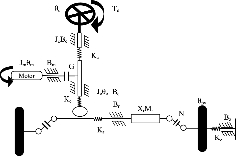
Figure 1: Steering system model
The steering wheel as in Fig. 1 is the main tool for the driver to steer the vehicle, and the driver applies torque to the steering wheel and steering control to the steering gear through the steering column [18]. According to the force of the steering wheel and the mechanical equations, the steering wheel moment balance equation is obtained as shown in Eq. (1).
In (1),
In Eq. (2),
In Eq. (3),
The constructed steering model will be connected to the motor, and the process will be mediated by the embedded controller to realize remote control. The unmanned steering motor adopts the mainstream brushed DC motor, and the mathematical model is shown in Fig. 2.
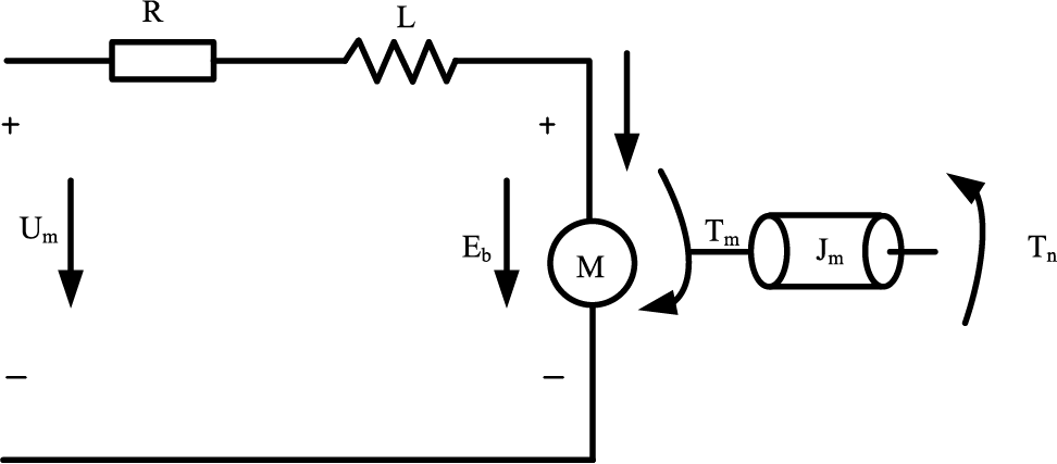
Figure 2: Mathematical model of steering motor
The motor and the steering shaft are connected by a turbine worm gear reduction mechanism. In which the turbine engages with a helical gear fixed on the steering output shaft to decelerate the rotational motion of the motor and then output it from the output shaft. The control model is shown in Eq. (6).
In Eq. (6),
The overall control of the robot is carried out under the sub-control of the above measurement module and network control module, while the details of the control are realized by the embedded controller, and the whole control logic is shown in Fig. 3.
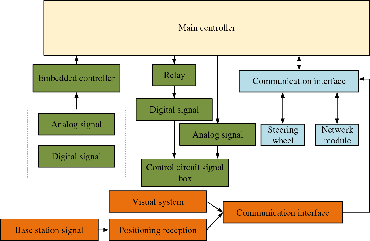
Figure 3: Overall control logic of pavement construction robot
The core controller in the control module of Fig. 3 is the module that implements the overall management of the system, and its role is to allow each controller to cooperate with the division of labor, so the corresponding I/O will be selected to connect with it. The purpose of the signal input and output module is to signal control all the control mechanisms except the steering device, while the total communication line interface takes over the signal control of the steering device and the measurement signals such as live view information.
3.2 Design Path of Construction Robot Based on Decision Control
Based on the clear overall framework, the decision control based on perception information will be carried out, and the control method and path will be the focus of the design, which is roughly divided into the analysis decision, remote control, and execution part. The remote control part is operated by human in the interaction interface, the analysis decision means to collect and analyze the information of the controller and interaction layer, and the execution part is the implementation of the driven operation. The sensing unit needs to obtain visual information and 3D spatial position, where the positional information will be realized by RTK-GNSS module, and the distributed position information is shown in Fig. 4.
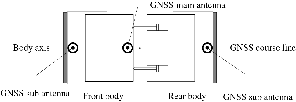
Figure 4: GNSS antenna deployment information
In Fig. 4, the roller is an articulated structure, and the direction of rolling has certain characteristics, so the GNSS main antenna is deployed in the middle of the axis line of the whole roller, and the secondary antenna is deployed in the front and rear vehicle axis lines. The direction setting of the heading line needs to consider the positioning role of the route where the main and secondary antennas are located, and the purpose of setting them parallel to the axis body of the robot is to facilitate the calculation of the heading angle. Setting the primary antenna at the geometric center of the robot and the secondary antenna at the ends is to facilitate the positioning of the robot and thus provides assistance for attitude angle determination. For the measurement system, the RTK-GNSS positioning module used in the study is a 3D coordinate system based on geodetic latitude
The geometric analysis of coordinates under Gauss-Krueger projection projects the coordinates of WGS-84
The omitted part of Eq. (7) is the higher-order term expanded to the inner part above the accuracy, which is omitted due to the actual accuracy requirements of the construction. Where
The a of Eq. (8) is the long radius of the ellipsoid, e is the first eccentricity,
The projection coordinates are transformed from a Gauss-Krueger coordinate system to a Cartesian coordinate system in accordance with Eq. (10) for the actual drawing. After the construction positioning system and method is constructed will be constructed for the path planning, the process operator runs the planning based on the positioning information on the interactive device. The specific process requires first obtaining each boundary of the construction area, and after setting the speed according to the data, the computing process uses linear regression fitting combined with circular arc fitting to identify the boundary and obtain the good line contour of the construction area. The obtained contour will be used as the outer path of roller rolling, and uniformly set the acquisition points as the planning result of the embedded controller. The path planning based on the relative coordinate system will be saved to be used as a basis for remote control. The linear fit involved in this process will be used to calculate the analytic equation for the outer long edge of the straight road area, if there are
The
The fitted long and short edges are coupled after completing the above lapping process to find the four vertex positions, and the number of path strips can be calculated based on the short edge length and overlap width as in Eq. (14).
The
4 Simulation and Testing of Control Performance of Pavement Construction Robot
The simulation experiment of this study is carried out in CarSim and Simulink platforms. The experimental contents include the steering system, path planning ability, and practical application in the construction of automatic robots. Before the experiment, the simulation interface needs to be adjusted to meet the experimental requirements, as shown in Fig. 5.
Figure 5: Digital analog interface
After adjusting the system parameters required by the experiment according to Fig. 5, the simulation experiment of steering automation for the whole vehicle model is studied. During the experiment, in order to ensure the real-time performance of the tracking control process, the researchers followed closely with a stopwatch. The scene design in the experiment includes forest and garden. In these two scenes, the steering angle of the car and the trajectory of the whole car are shown in Fig. 6.
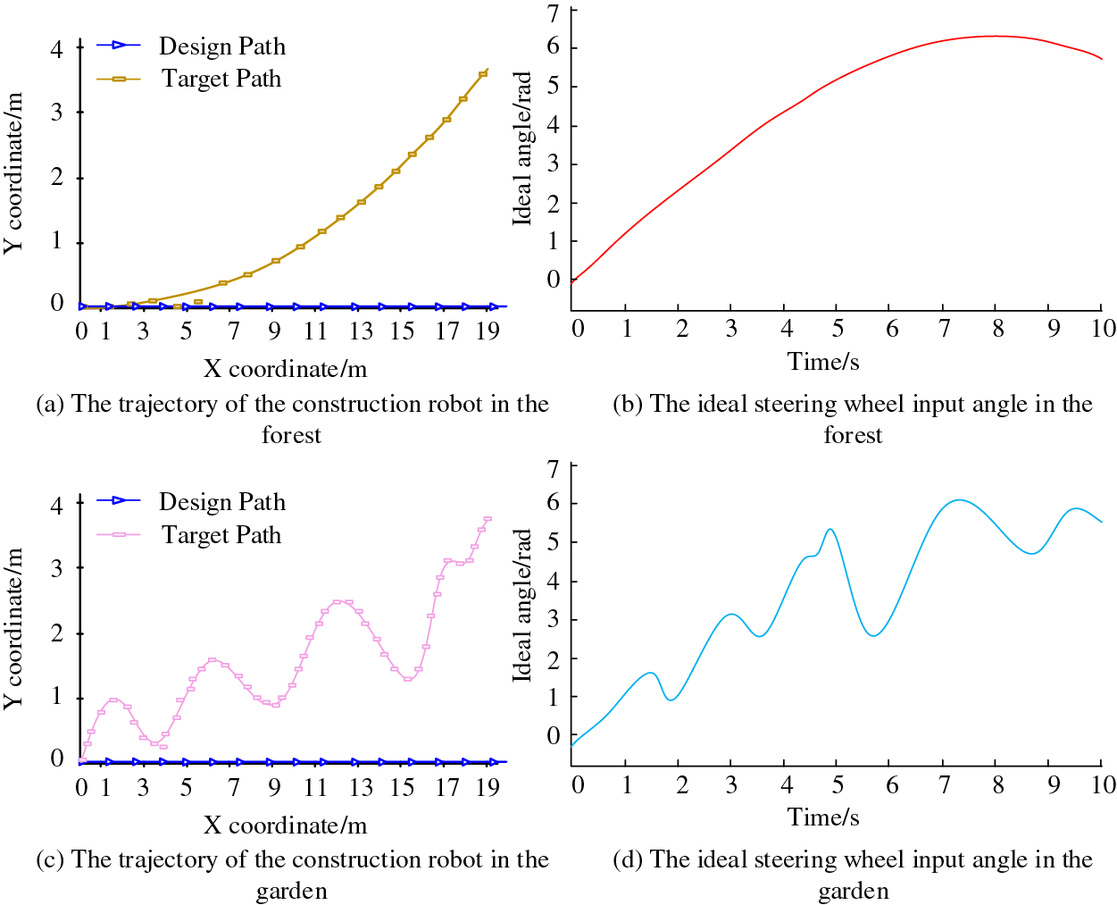
Figure 6: Steering control simulation results
According to the simulation results in Fig. 6, the actual steering wheel turning angle meets the ideal turning angle under the target path and the design path, which indicates that the PI controller meets the control accuracy requirements and the vehicle can steer according to the predetermined trajectory. The simulation of path planning will be carried out under the normal control of the steering wheel. The simulation also needs real-time data from the live monitoring module of the automatic construction robot, so the practicality of the relevant module will be tested in this session. The steel wheel width of the roller used in the study is 2130 mm and three rounds of road compaction are implemented, where the compaction of the straight path is shown in Fig. 7.
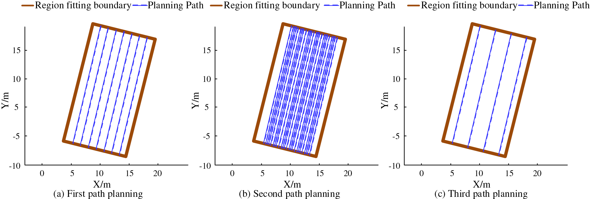
Figure 7: Straight path planning results
According to the simulation results reflected in Fig. 7, the path planning results used in the study are always within the boundary of the zone fit, and all three sets of multiple compaction results are within the zone with 100% compaction, which indicates that the path planning method and the optimized path are effective, and the linear fitting approach works well for straight path planning. Simulation of curved paths in the same environment, the results are shown in Fig. 8.
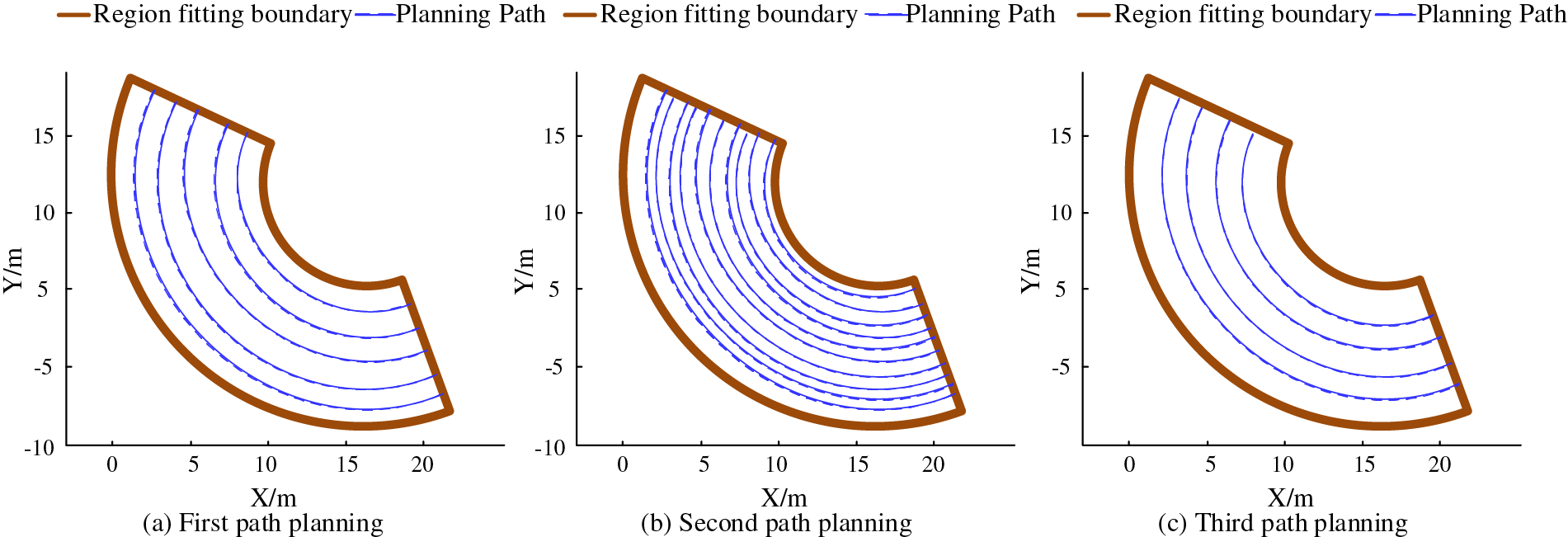
Figure 8: Curve path planning results
According to the simulation results in Fig. 8, the path planning process and demand of the curved road are more complex and non-linear fitting, but still shows good performance under the processing of circle fitting, and the results of path planning still do not exceed the fitting limits of the zone, and the three groups of multiple compaction still reach 100%. After testing the good path planning performance, the compaction of straight and curved roads will be analyzed in gradient according to the color shades, respectively, and the process index will be presented in this way, and the results are shown in Fig. 9.
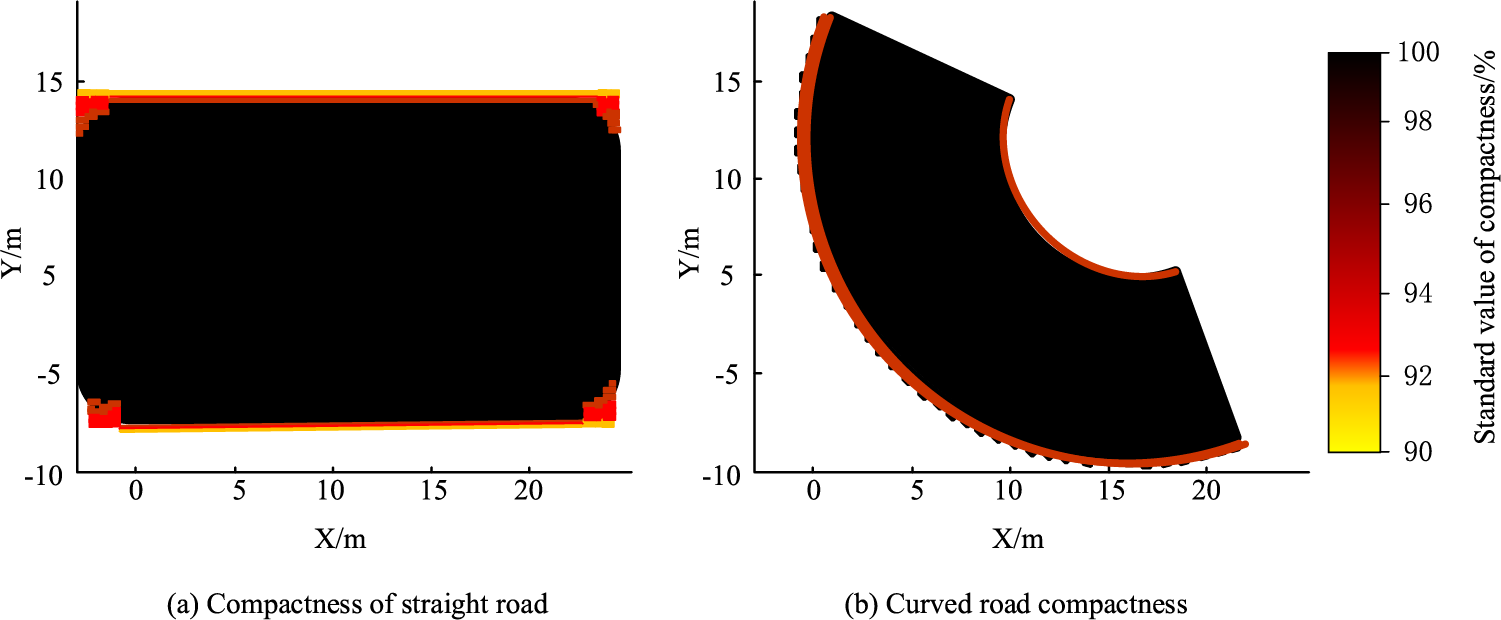
Figure 9: Compaction test results
As shown in the compaction test in Fig. 9, the compaction degree of both straight line and curved areas is better, and most of the area is in complete compaction, and both of the areas that are not completely compacted appear at the edges. From the data, the straight line area had the best compaction with an average compaction rate of 92.11%, and more than 95% of the area was above 96%, while 85.49% of the curved area had 100% compaction. This result fully illustrates that the route planning taken in the study can meet the compaction working condition requirements, and for road construction can be driven with the construction operation, and the best path during construction will be obtained according to the actual situation and planning method in the correct driving process. The path planning test will be followed by the analysis of the path error of the actual construction conditions to obtain the deviation value between the actual work and the preset heading. In practical experiments, the Random Forest (RF) algorithm, Extreme Gradient Boosting (XGBoost) algorithm, and Spotted Hyena (SH) algorithm are studied and compared with the algorithms proposed in the study. And the error will be calculated iteratively according to the PID control technique mentioned above, and the lateral error is shown in Fig. 10.
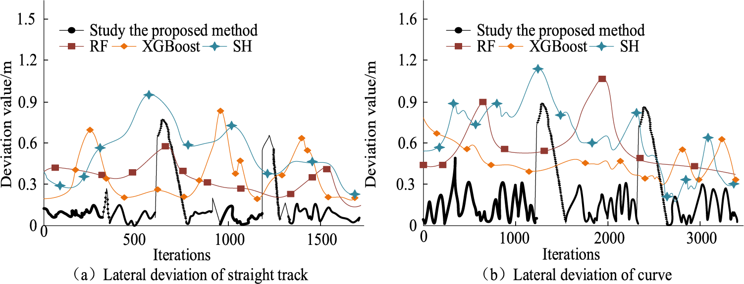
Figure 10: Results of path deviation in the working phase
According to the path tracking error results in Fig. 10, it can be seen that both straight and curved paths the robot has a periodic error change, the error is larger in the region just at the moment of steering, but soon the error falls from the peak to the usual error, except for the peak of the error are not more than 0.6, the average lateral error throughout the process is always maintained within 20 cm, of which the straight path can be maintained within 10 cm. This data has the best performance among the four algorithms. The data of RF, XGBoost, and SH algorithms are 0.9, 0.75, and 1.28, respectively, and their errors are all above 50 cm. For road construction, the road error should be controlled within 40 cm. The number of error iterations fluctuates periodically under PID control for the straight road compared to the curved section, which is probably due to the fact that the driving speed of the curved road is affected when the time is taken into account for steering measurement and the time per generation is increased, but this error magnitude can fully meet the road construction needs, so this design is feasible.
In the era of intelligent technology development, driverless technology is becoming more and more mature, and using this technology for road construction can not only reduce human cost and construction risk but also get more accurate decisions based on intelligent calculation. The intelligent construction robot proposed in the study is based on a road roller, using remote control technology to take over the steering control, and setting a reasonable automatic steering control module through mechanical modeling and mathematical analysis; meanwhile, the environment monitoring module is divided into positioning perception and real-world measurement, and this module is to provide a basis for decision making and control; in terms of path control and setting, it is divided into straight and curved paths according to road characteristics, and linear and circular fitting are used respectively the over-path calculation is performed. The simulation results show that the turning angle of the steering controller can meet the path setting requirements; the fitting degree of path planning for straight and curved roads reaches 100%, and in the actual compaction process, the compaction degree of more than 95% of the straight road part is above 96%, while 85.49% of the curved road area reaches 100%; the simulation of path tracking shows that the heading error based on environmental data is within 20 cm The simulation of path tracking shows that it can fully meet the current road construction requirements. In the follow-up work, we will develop automatic technology for different functions of mechanical equipment to help road construction. However, in the experiments carried out in the forest and garden terrain, the weather is sunny. For the field construction site, the weather conditions are complex and changeable, so it is equally important to study the automatic driving in various weather conditions. In addition, the path selection is only for straight lines and circles. For the field construction site, the road conditions are complex and changeable. Therefore, it is also important to study the automatic driving of various curvature paths, which will continue in future research.
Acknowledgement: None.
Funding Statement: The authors received no specific funding for this study.
Author Contributions: The authors confirm contribution to the paper as follows: study conception and design: Zhongping Chen, Weigong Zhang; data collection: Zhongping Chen; analysis and interpretation of results: Zhongping Chen, Weigong Zhang; draft manuscript preparation: Zhongping Chen. All authors reviewed the results and approved the final version of the manuscript.
Availability of Data and Materials: The data that support the findings of this study are available from the corresponding author upon reasonable request.
Conflicts of Interest: The authors declare that they have no conflicts of interest to report regarding the present study.
References
1. Muench, S. (2020). The road to sustainable highway construction practices. TR News: Transportation Research, 26, 33–37. [Google Scholar]
2. Tian, Y., Zhao, Y., Shi, Y., Cao, X., Yu, D. L. (2020). The indirect shared steering control under double loop structure of driver and automation. IEEE/CAA Journal of Automatica Sinica, 7(5), 1403–1416. [Google Scholar]
3. Rahimi Moghadam, K., Banigan, C., Ragan, E. D. (2020). Scene transitions and teleportation in virtual reality and the implications for spatial awareness and sickness. IEEE Transactions on Visualization and Computer Graphics, 26(6), 2273–2287. [Google Scholar]
4. Shao, S., Peng, Y., He, C. L., Du, Y. (2020). Efficient path planning for UAV formation via comprehensively improved particle swarm optimization. ISA Transactions, 97, 415–430. [Google Scholar] [PubMed]
5. Namazi, E., Mester, R., Lu, C., Li, J. Y. (2022). Geolocation estimation of target vehicles using image processing and geometric computation. Neurocomputing, 499, 35–46. [Google Scholar]
6. Guindel, C., Martin, D., Armingol, J. M. (2019). Traffic scene awareness for intelligent vehicles using ConvNets and stereo vision. Robotics and Autonomous Systems, 112, 109–122. [Google Scholar]
7. Xia, Y., Zhang, X., Ge, H., Hao, S., Zou, W. (2021). Optimal dispatching technology of distributed power generation based on situation awareness. American Journal of Electrical and Electronic Engineering, 9(1), 7–11. [Google Scholar]
8. Fu, H., Wu, B., Shao, Y. H., Zhang, H. Y. (2018). Scene-awareness based single image dehazing technique via automatic estimation of sky area. IEEE Access, 7, 1829–1839. [Google Scholar]
9. Soni, R., Kumar, B., Chand, S. (2019). Text detection and localization in natural scene images based on text awareness score. Applied Intelligence, 49(4), 1376–1405. [Google Scholar]
10. Fu, M. Y., Fang, W., Gao, S., Hong, J. H., Chen, Y. Z. (2022). Edge computing-driven scene-aware intelligent augmented reality assembly. The International Journal of Advanced Manufacturing Technology, 119(11), 7369–7381. [Google Scholar]
11. Kumar, S. P., Biswal, G. (2022). Utilization of reclaimed asphalt pavement (RAP) as granular sub-base material in road construction. Materials Today: Proceedings, 60(1), 288–293. [Google Scholar]
12. Sung, S. M., Yun, B. Y., Song, M. H., Cho, J. S. (2020). Drone operation plan at road construction site. Journal of The Korean Society of Industry Convergence, 23(5), 709–716. [Google Scholar]
13. Jung, K. Y., Park, J. K. (2021). Roughness analysis of paved road using drone LiDAR and images. Journal of the Korean Society of Surveying Geodesy Photogrammetry & Cartography, 39(1), 55–63. [Google Scholar]
14. Gebretekle, Y. T., Kamau, D. W., Raoufi, M. (2022). Digitalization opportunities road mapping tool (DORMT©A framework to assess digitalization opportunities in construction organizations. Canadian Journal of Civil Engineering, 49(2), 171–182. [Google Scholar]
15. Kavitha, G., Anbazhagan, S., Mani, S. (2021). Geospatial technology for landslide susceptibility mapping along the Vathalmalai Ghat road section, South India. Journal of Geology, Geography and Geoecology, 30(4), 683–691. [Google Scholar]
16. Lucas-Estañ, M. D. C., Coll-Perales, B., Gozalvez, J. (2020). Redundancy and diversity in wireless networks to support mobile industrial applications in Industry 4.0. IEEE Transactions on Industrial Informatics, 17(1), 311–320. [Google Scholar]
17. Su, Y. H., Young, K. Y. (2018). Effective manipulation for industrial robot manipulators based on tablet PC. Journal of the Chinese Institute of Engineers, 41(4), 286–296. [Google Scholar]
18. He, Y. B., Chen, J. J. (2019). Compound control and parameter self-tuning of permanent magnet synchronous motor. Journal of Mechanical & Electrical Engineering, 36(9), 995–1000. [Google Scholar]
19. Kim, G. B., Jeong, G. H., Jeon, J. B. (2019). Problems and improvement measures for the transformation of world geodetic system. Journal of Cadastre & Land Informatix, 49(2), 123–134. [Google Scholar]
20. Valiev, R. R., Cherepanov, V. N., Nasibullin, R. T., Stepanova, E. V., Faiskanova, K. M. et al. (2019). Calculating rate constants for intersystem crossing and internal conversion in the Franck-Condon and Herzberg-Teller approximations. Physical Chemistry Chemical Physics, 21(34), 18495–18500. [Google Scholar] [PubMed]
Cite This Article
 Copyright © 2024 The Author(s). Published by Tech Science Press.
This work is licensed under a Creative Commons Attribution 4.0 International License , which permits unrestricted use, distribution, and reproduction in any medium, provided the original work is properly cited.
 Downloads
 Citation Tools