
 Submit a Paper
 Propose a Special lssue
 Open Access
ARTICLE
A Fractional Order Fast Repetitive Control Paradigm of Vienna Rectifier for Power Quality Improvement
1
School of Electrical and Control Engineering, Shaanxi University of Science and Technology, Xi’an, China
2
School of Automation, Northwestern Polytechnical University, Xi’an, China
3
Electronics Engineering Department, University of Engineering and Technology Peshawar, Khyber, PakhtunKhwa, Pakistan
* Corresponding Author: Xintao Luo. Email:
(This article belongs to the Special Issue: Artificial Intelligence in Renewable Energy and Storage Systems)
Computer Modeling in Engineering & Sciences 2023, 134(2), 1159-1176. https://doi.org/10.32604/cmes.2022.021850
Received 08 February 2022; Accepted 29 March 2022; Issue published 31 August 2022
 View Full Text
 Download PDF
Abstract
Due to attractive features, including high efficiency, low device stress, and ability to boost voltage, a Vienna rectifier is commonly employed as a battery charger in an electric vehicle (EV). However, the 6k ± 1 harmonics in the acside current of the Vienna rectifier deteriorate the THD of the ac current, thus lowering the power factor. Therefore, the current closed-loop for suppressing 6k ± 1 harmonics is essential to meet the desired total harmonic distortion (THD). Fast repetitive control (FRC) is generally adopted; however, the deviation of power grid frequency causes delay link in the six frequency fast repetitive control to become non-integer and the tracking performance to deteriorate. This paper presents the detailed parameter design and calculation of fractional order fast repetitive controller (FOFRC) for the non-integer delay link. The finite polynomial approximates the non-integer delay link through the Lagrange interpolation method. By comparing the frequency characteristics of traditional repetitive control, the effectiveness of the FOFRC strategy is verified. Finally, simulation and experiment validate the steadystate performance and harmonics suppression ability of FOFRC.Keywords
Industrialization requires a lot of energy consumption [1], and the pollution problem caused by the consumption of fossil energy [2] is becoming more and more serious. Therefore, new energy can flourish, and electric vehicle [3] is one of the hotspots. Supercapacitor [4] as an energy storage technology to provide energy for electric vehicles [5] has been widely concerned by scholars. Literature [6–8] has done research on the characteristics of new materials for capacitors. With the continuous expansion of the market scale of electric vehicles [9], the high-power DC charging technology of fast charging has developed rapidly, that is, the common DC charging pile in the market [10]. The main power of the DC charging pile is cascaded by the front stage rectifier and the rear stage DC/DC converter [11]. The front stage rectifier mainly includes traditional bridge PWM rectifier and Vienna rectifier. Compared with the traditional bridge PWM rectifier, Vienna rectifier has fewer switching devices, and the voltage stress borne by the switch devices is half of the bus voltage on the DC side. There is no need to consider the direct connection of the upper and lower bridge arms and the dead band setting of the switch devices [9]. Therefore, Vienna rectifier is generally used as the front stage circuit. At the same time, as the interface converter between power grid and load, rectifier plays an important role in restraining current harmonics [12].
The key to restraining current harmonics, reducing total harmonic distortion (THD) and improving power quality lies in the control of AC current [13]. The literature [14] adopted the current control strategy based on PI control, which is widely used, but the control of AC harmonic by PI controller is not ideal. In order to control AC current harmonics, the control strategy based on internal model principle has been widely studied by scholars. The literature [15] used resonance control to suppress periodic current harmonics, but it can only be controlled for a specific harmonic.
Repetitive control (RC) can effectively realize the accurate tracking of harmonic signal by accumulating and tracking the error cycle by cycle [16], but there is an inherent delay of fundamental wave period [17]. In literature [18], a steady-state compensator is designed using H∞ theory for RC based on internal model principle. However, the computational complexity of the algorithm in a complex grid connected environment is a little complex, especially considering the nonlinear and unbalanced load. The literature [19,20] proposed a multi-rate RC control strategy and applied it in a PWM inverter. However, with nonlinear loads, the peak tracking error may become larger. The literature [21] proposed a filter that can estimate the unknown input of the system and effectively suppress the noise. The literature [22] used an auxiliary function based on linear interpolation to improve RC to shorten cycle delay. However, it does not take into account the situation when the grid frequency is offset. The literature [23] proposed a fast repetitive control (FRC), whose control period is only half of that of traditional RC, but when the RC frequency is further improved, the number of periodic delay points may be non-integers, which will affect the tracking accuracy. Moreover, the FRC cannot work normally when the frequency fluctuates. When the grid frequency shifts, its resonant frequency will deviate from the actual harmonic frequency of the grid [24], resulting in large control error. The literature [25] proposed two FRC methods to adapt to frequency fluctuation. One is to reduce the sensitivity to frequency fluctuation by reducing the internal model coefficient Q, but it will affect the gain; One is to change the traditional RC structure, so that the RC link becomes the sum of multiple resonant terms, so as to achieve frequency adaptation. However, due to the large resonant bandwidth, the rapidity of response is affected.
In order to solve the problem that the delay link of fast repetitive control becomes non-integer when the power grid frequency fluctuates, a fractional order fast repetitive control (FOFRC) strategy is proposed. The Vienna rectifier system is modeled, the Lagrange interpolation method is used, and the Lagrange interpolation method is used to replace the non-integer delay link with polynomial, which shortens the periodic delay of the traditional RC and makes the controller to accurately track the expected output. From the perspective of frequency characteristics, it is analyzed and compared with traditional RC and FRC. At the same time, a zero phase shift filter is designed to improve the stability and anti-interference of the system. The simulation and experimental results show that the FOFRC strategy has better steady-state performance, suppresses the THD of AC current at the grid side and has less AC harmonic component.
The rest chapters are arranged as follows: The second part introduces the topology and control strategy of Vienna rectifier; The third part analyzes the problems of rapid repetitive control; In the fourth part, a fractional order fast repetitive control strategy based on Lagrange interpolation polynomial is proposed, and its stability is proved. In the fifth part, the proposed control strategy is verified by simulation and experiment. The sixth part summarizes the full paper.
2 Topology and Control Strategy of Vienna Rectifier
This article takes the Vienna rectifier as the research object. The topological of Vienna rectifier is shown in Fig. 1. ea, eb, ec are the voltages of AC side, L is input side inductor, R is the equivalent resistance, ia, ib, ic are the three-phase AC grid current, D1~D6 are uncontrollable diodes, ip and in are the current flowing through the DC bus respectively, and io is the neutral point current at the DC side, C1 and C2 are series equivalent capacitors on the output side, ic1 and ic2 are the currents flowing through capacitors C1 and C2, respectively, RL is DC side resistive load, iL is the load current, Sa, Sb, Sc are bidirectional switches, and each bidirectional switch is composed of two IGBT power devices in series.

Figure 1: Three phase Vienna rectifier topology
The double closed-loop control strategy for Vienna rectifier is shown in Fig. 2. The current inner loop adopts the composite control strategy to effectively control the fundamental wave and 6k harmonics, reduce the THD of AC input current and improve power quality.

Figure 2: Droop control block diagram
3.1 Traditional RC and Its Rapidity
The current inner loop control [14] block diagram of traditional repetitive control is shown in Fig. 3. In Fig. 3, block diagram of traditional repetitive control, N is the number of samples in a cycle, that is, the ratio of sampling frequency to grid frequency. kr is the gain coefficient, Q(z) is the internal model coefficient, S(z) is the correction link,zk is the phase lead link, P(z)is the controlled object.

Figure 3: Current control block diagram of traditional repetitive control
The transfer function of traditional repetitive control is shown in Eq. (1).
If the grid frequency is defined as f0, there is a delay time T0(T0=1/f0), which just corresponds to a periodic sampling point N. Therefore, repetitive control does not work in the first cycle of dynamic response, resulting in poor dynamic response ability. Moreover, when N (periodic sampling points) is relatively large, it occupies a large memory.
Aiming at the problem of traditional RC, the sampling frequency is increased to reduce the number of periodic delay points and improve the dynamic performance. The dynamic performance of RC with different sampling frequencies is shown in Fig. 4. It can be seen that the delay time decreases with the increase of sampling frequency, and the occupied memory unit also decreases.

Figure 4: Dynamic performance curve of RC with different sampling frequencies
In practice, according to the requirements of the controlled object, only the harmonics at a specific frequency need to be suppressed. The harmonic of the three-phase Vienna rectifier AC side current in this paper is mainly 6k ± 1 harmonic [22], which changes into 6k harmonic in dq rotating coordinate system after coordinate transformation. According to the characteristics of 6k harmonics, six times frequency FRC strategy is adopted. The current inner loop control block diagram of six octave FRC strategy is shown in Fig. 5.
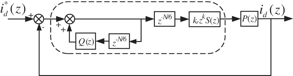
Figure 5: Current control block diagram of FRC
The transfer function of the FRC strategy in Fig. 5 is shown in Eq. (2).
Although FRC strategy improves the dynamic performance of the system and reduces the use of memory in digital implementation, when the designed sampling frequency is unreasonable, N/6 is not an integer and can only be approximately rounded in discrete, resulting in large deviation between discrete form

Figure 6: Comparison of Bode diagram of fast repetitive control in continuous domain and discrete domain
Even if the sampling frequency has been reasonably designed, because the actual grid frequency f0 will offset, N/6 will not be an integer, resulting in attenuation of control gain and degradation of tracking performance. Assuming that the grid frequency offset is 0.6 Hz, the Bode diagram of FRC strategy near the 5th harmonic is shown in Fig. 7. At this time, the 5th harmonic frequency is shifted by 3 Hz, the corresponding gain is attenuated to 10.7 dB, and the control effect is obviously weakened.

Figure 7: Fast repetitive control Bode diagram of power grid frequency offset ±0.6 Hz
4 Proposed Fractional-Order Fast Repetitive Control Strategy
4.1 Fractional Order Based Fast Repetitive Control
In this paper, a fractional order fast repetitive control strategy is proposed to solve the non-integer delay caused by power grid frequency offset. Firstly, Lagrange interpolation polynomial is used to replace the fractional part of non-integer delay link. Secondly, zero phase shift filter is used to design internal model link to improve the stability and gain of the system. Finally, good steady-state performance is achieved, the THD of AC current at the grid side is reduced, the harmonic suppression ability is improved, and the stable operation of the system is realized.
In order to approximate the non-integer part, fractional order fast repetitive control is introduced, and the delay points are divided into two parts [24], as shown in Eq. (3):
where Ni is an integer and d is a non-integer. According to the Lagrange interpolation method, the approximate function expression of
where h(n) is the polynomial coefficient, and M is the order of the interpolation polynomial. The direct form implementation based on Lagrange interpolation polynomial is shown in Fig. 8.

Figure 8: Direct form implementation of Lagrange interpolation
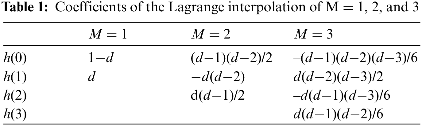
According to h(n) from (4), the coefficients for M = 1, 2, and 3 are given, in Table 1.
The control block diagram of FOFRC strategy is shown in Fig. 9.

Figure 9: Block diagram of the proposed FOFRC
In order to realize the good control of fundamental and harmonic, the compound control strategy of PI control and fractional order fast repetitive control in parallel is adopted. The transfer function of the controlled object P(s) is 1/(Ls+R), and P(z) is discretized by bilinear transformation.
According to Fig. 10, the transfer function of the current inner loop is in Eq. (5):

Figure 10: Current inner loop control block diagram based on FOFRC
where
then
When the characteristic roots of the system are in the unit circle, the discrete system is stable. According to Eq. (6), the stability of the current inner loop needs to meet the following two conditions:
1) The roots of H0 are inside the unit circle;
2)
Condition 1) shows that the proportional control is stable when the root of H0 is in the unit circle; Condition 2) shows that the FRC is stable.
FOFRC is improved from the basis of the traditional RC, so the FOFRC controller can be designed using the method of the traditional controller.
The internal mode coefficient Q(z) is usually a constant less than 1 or a low-pass filter. When Q(z) is a constant less than 1, the closer the constant is to 1, the greater the gain of the system, but the easier it is to be unstable; When Q(z) is in the form of low-pass filter, its amplitude gain is higher at low frequency, but there is a problem of phase lag. In order to ensure the control effect, the zero-phase shift filter is selected [26–28]. The general expression of zero phase shift filter is as Eq. (7):
where M is the order of the filter, a0, ai is the coefficient. In practical application, M is usually taken as 1. The expression is as Eq. (8):
Convert it to frequency domain, the expression is as Eq. (9):
In order to ensure the stability of fast repetitive controller,
From Eq. (10), the following expression in Eq. (11) is obtained:
Since the zero phase shift filter has high amplitude gain at low frequency and attenuation at high frequency, therefore, when ωTs = 0, let
its expression in Eq. (12) is given
As shown in Fig. 10, the current inner loop is a parallel form of proportional control and fractional order fast repetitive control. The compensator S(z) is designed according to the expected function correction method, and can be expressed as Eq. (13):
The sampling frequency of the controller is 20 kHz, so the cut-off frequency of the compensator is selected as f = 1 kHz, ω = 2000π, the damping coefficient is selected as 0.707, and the expression of the compensator in the discrete domain can be obtained as Eq. (14):
After adding the compensator, the phase of the controlled object lags, as shown in Fig. 11. At this time, the lead link zk is needed for compensation.

Figure 11: The compensation effect of S(z)
The order of the lead link is determined according to the effect of the lead link. The phase frequency characteristics of zkS(z)P(z) under different lead orders are shown in Fig. 12. It can be seen that when k = 3, the compensation for phase lag is the best. In this paper, k = 3.

Figure 12: zk compensation effect of different orders
In order to make the system have better stability and dynamic performance, according to the stability condition of the current inner loop, the root of H0 should be in the right half plane of the unit circle and close to the coordinate origin, and the Nyquist curve of H1 should approach the center of the unit circle. Considering the situation of H0 and H1, kp = 20 is taken in this paper. Generally, kr is a constant less than 1. The smaller the value of kr, the better the stability of the system. In this paper, the repetitive control gain kr is selected as 0.2.
Assuming that the sampling frequency of the system is 20 kHz, the number of periodic delay points of fast repetitive control is

Figure 13: Comparison of Bode diagram of different repetitive control
Since N/6 is not an integer, when the FRC is realized by discrete digitization, the resonant frequency shifts to 298 Hz at 300 Hz and 896 Hz at 900 Hz. This effect is more obvious at higher frequencies, and the deviation of resonant frequency reaches 10 Hz, as shown in Figs. 13a–13c, respectively. After optimizing the sampling frequency of the system to 20.7 kHz, it can be seen that the FRC after optimizing the sampling frequency can achieve the effect of traditional RC, so as to ensure the accurate tracking of harmonics.
If the sampling frequency of the optimized system is 20.7 kHz, N/6 = 69. If the grid frequency does not shift, the control effect of FRC can be guaranteed. Assuming that the grid frequency offset is +0.6 Hz, the number of periodic delay points of FRC
If the sampling frequency of the optimized system is 20.7 kHz, N/6 = 69. If the grid frequency does not shift, the control effect of FRC can be guaranteed. Assuming that the grid frequency offset is +0.6 Hz, the number of periodic delay points of FRC.
When non-integer d is close to M/2, the interpolation effect is the best [17]. d = 1.2, closest to 1, so M/2 = 1, M = 2.
According to the calculation formula when M = 2 in Table 1, bring in the value of d to calculate h(0), h(1) and h(2). Fractional delay is obtained Eqs. (15) and (16):
Bode diagrams of traditional RC, FRC and FOFRC are shown in Fig. 14. After the grid frequency is offset, the actual frequency of 5th and 7th harmonics in dq coordinate system shall be 50.6 × 6 = 303.6 Hz. Because the traditional RC has no frequency adaptive ability, its fifth harmonic frequency is still 300 Hz; FRC causes the resonant frequency to shift to 314 Hz due to approximate rounding; The FOFRC resonant frequency is finally fitted to 304 Hz. This difference in frequency tracking accuracy is more obvious at higher harmonics. As shown in Fig. 14b, the theoretical offset value of 17th and 19th harmonics in dq coordinate system is 0.6 × 18 = 10.8 Hz, the actual offset of FRC is 41 Hz, and the actual offset of FOFRC method is 11 Hz. The tracking effect of frequency offset is obviously better than FRC.

Figure 14: Comparison of Bode diagram of different repetitive control in power grid frequency offset
5 Simulation and Experimental Verification
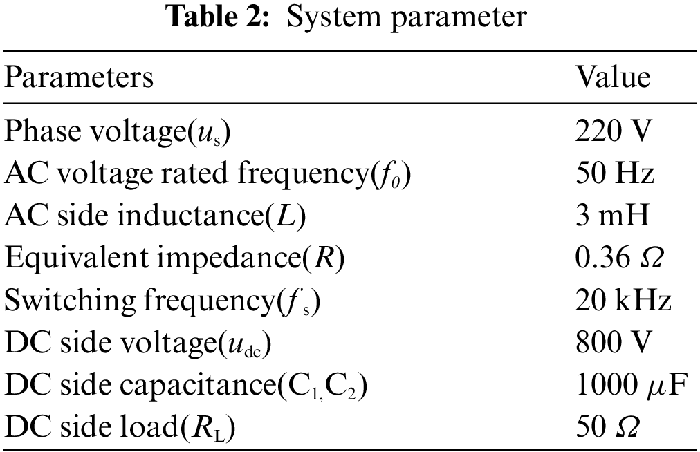
In order to verify the effectiveness of the method proposed in this paper, the simulation model of the Vienna rectifier control system is built in MATLAB, and the simulation parameters are shown in Table 2.
5.1 Simulation Verification of Fractional Order Fast Repetitive Control Strategy
The simulation waveform diagrams in Fig. 15 are steady state AC current waveforms from traditional RC, FRC and FOFRC strategies. When the grid frequency offset is +0.6 Hz, because the traditional repetitive control has no frequency adaptive ability, the power grid current waveform distortion is serious, and the THD is as high as 8.19%. The FRC strategy has a certain frequency adaptive ability, and the THD is improved to 5.87%, but the discrete approximate rounding still leads to a large THD. The FOFRC strategy has good adaptability to frequency offset, the grid current waveform is significantly improved, the THD is further reduced to 1.84%, and high steady-state accuracy is realized.

Figure 15: Steady state AC current waveforms with grid frequency offset of 0.6 Hz (a) traditional RC; (b) fast repetitive control; (c) FOFRC
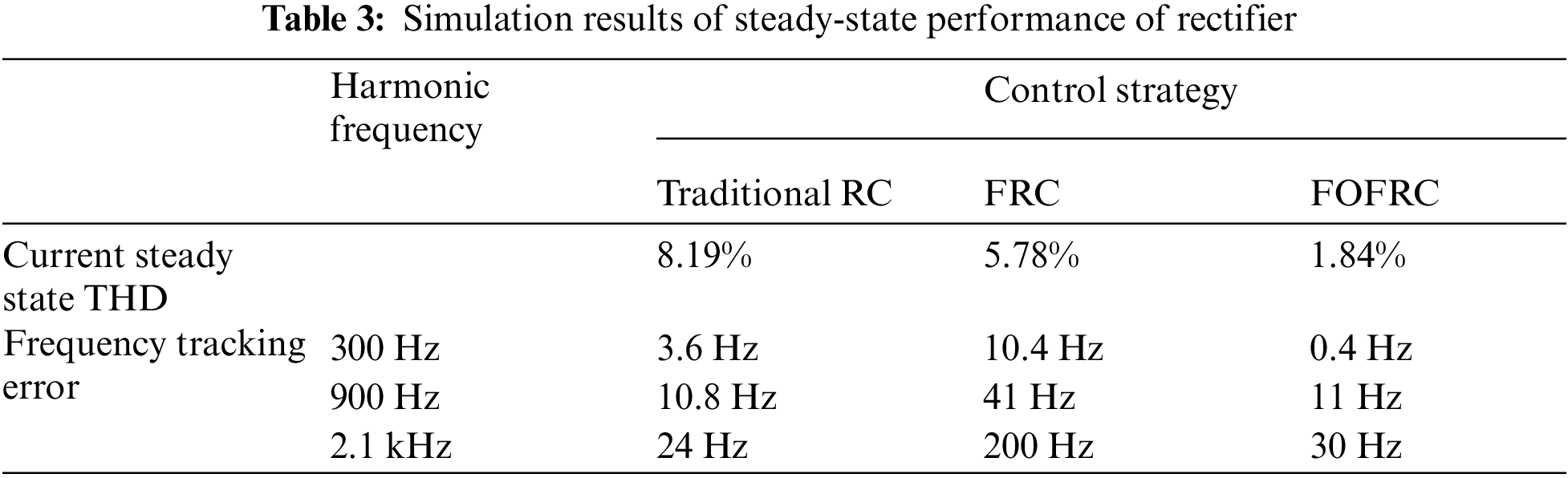
In order to further compare and analyze the steady-state performance of rectifier, THD of steady-state input current and tracking error, the results are shown in Table 3. It can be seen from Table 3 that the fractional order fast repetitive control strategy proposed in this paper can greatly reduce the frequency tracking error, significantly reduce the current steady-state THD, and significantly improve the steady-state characteristics of the rectifier, so as to suppress the influence of harmonics on the current waveform distortion. The current waveform distortion can be observed in the simulation. The control method proposed in this paper has good waveform.
5.2 Experimental Verification of Fractional Order Fast Repetitive Control Strategy
According to the theoretical analysis and simulation above, an experimental prototype of Vienna rectifier based on TMS320F28335 is built as shown in Fig. 16. The experimental parameters are the same as those in Table 2. Tektronix P5200A different probe is used to measure the voltage signal, Tektronix TCPA300 probe is used to measure the current signal. The Tektronix MDO 3034 mixed domain oscilloscope is used to capture and analyze the signals. The total harmonic distortion is measured by Fluke 43B Power Quality Analyzer.

Figure 16: Experimental prototype
The grid frequency offset is 0.6 Hz, the THD diagrams of the traditional RC, FRC and FOFRC strategies captured by the Fluke 43B Power Quality Analyzer are shown in Fig. 17. The THD of 2.6% from the FOFRC strategy is obviously less than the THD of 6.8% from the FRC strategy and the THD of 8.5% from the traditional RC strategy. These results illustrate that the FOFRC strategy can track the expected value more accurately than the traditional RC and FRC strategies. The harmonic compensation performance of the system is improved and has better performance harmonic suppression capability.

Figure 17: THD diagrams with grid frequency offset of 0.6 Hz: (a) traditional RC; (b) fast repetitive control; (c) FOFRC
The grid frequency offset is 0.6 Hz, the steady-state AC current waveforms of traditional RC, FRC and FOFRC strategies are shown in Fig. 18. The AC current of power grid is seriously distorted in the waveform of traditional RC, the current waveform is improved in the waveform of FRC strategy, but some distortion can still be seen. The power grid current waveform is significantly improved in the waveform of FOFRC, and the current waveform is smoother and sinusoidal.
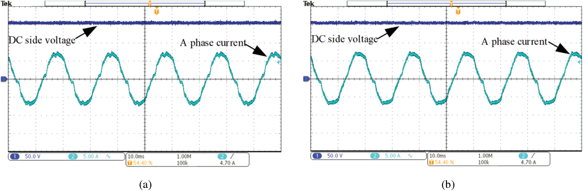

Figure 18: Steady state AC current waveforms with grid frequency offset of 0.6 Hz: (a) traditional RC; (b) fast repetitive control; (c) FOFRC
After the current THD data is derived by the power quality analyzer, the results are shown in Table 4. By observing the data in Table 4, the proposed strategy in this paper reduces the THD of current from 8.5% to 2.6%, which verifies the effectiveness of this method in improving the steady-state characteristics of rectifier. Due to the influence of noise and sensor accuracy in the hardware experiment, the THD of the experimental current waveform is higher than that of the simulated waveform current. However, compared with the THD under each control method in the experiment, the method proposed in this paper greatly reduces the current THD without obvious distortion.

Aiming at the widely concerned interaction technology between electric vehicle and power grid, this paper analyzes the typical topology Vienna rectifier suitable for electric vehicle DC charging pile. On this basis, considering the problem that the traditional repetitive control has poor steady-state accuracy and cannot accurately track the expected output in the case of power grid frequency offset, a fractional order fast repetitive control is proposed, the combination of fractional order fast repetitive control and proportional control is applied to the current inner loop.
Firstly, the reason why the repetitive control delay link in power grid frequency offset is non-integer is analyzed. Secondly, the non-integer delay link that cannot be realized by discrete system is approximated by Lagrange interpolation polynomial, and the fractional delay element is used to overcome the influence of non-integer periodic delay, which effectively improves the fitting accuracy. The simulation and experimental results show that the FOFRC controller effectively improves the frequency characteristics of repetitive control, ensures the steady-state accuracy of repetitive control in the case of grid frequency offset, and reduces the current THD of repetitive control in the case of grid frequency offset. Compared with traditional RC and FRC, the steady-state sinusoidal AC current under FOFRC is smoother, and the THD is only 2.6%. Therefore, Vienna rectifier with FOFRC has better steady-state performance and harmonic suppression ability.
However, the parallel combined control has coupling to the control effect. In the next step, the coupling analysis of the combined control to the control effect will be carried out. In addition, the engineering application and popularization of control strategy is also a problem worthy of discussion.
Acknowledgement: The authors would like to thank the editor and the reviewers for their constructive comments which improve the quality of the paper.
Funding Statement: This research was funded by the Xi’an Science and Technology Plan Project, Grant No. 2020KJRC001 and the Xi’an Science and Technology Plan Project, Grant No. 21XJZZ0003.
Conflicts of Interest: The authors declare that they have no conflicts of interest to report regarding the present study.
References
1. Feng, X., Li, Q., Wang, K. (2021). Waste plastic triboelectric nanogenerators using recycled plastic bags for power generation. ACS Applied Materials & Interfaces, 13(1), 400–410. DOI 10.1021/acsami.0c16489. [Google Scholar] [CrossRef]
2. Xu, H., Du, H., Kang, L., Cheng, Q., Feng, D. et al. (2021). Constructing straight pores and improving mechanical properties of gangue-based porous ceramics. Journal of Renewable Materials, 9(12), 2129–2141. DOI 10.32604/jrm.2021.016090. [Google Scholar] [CrossRef]
3. Wang, K., Liu, C. L., Sun, J. R., Zhao, K., Wang, L. C. et al. (2021). State of charge estimation of composite energy storage systems with supercapacitors and lithium batteries. Complexity, 2021, 8816250. DOI 10.1155/2021/8816250. [Google Scholar] [CrossRef]
4. Liu, C., Li, Q., Wang, K. (2021). State-of-charge estimation and remaining useful life prediction of supercapacitors. Renewable and Sustainable Energy Reviews, 150(2), 111408. DOI 10.1016/j.rser.2021.111408. [Google Scholar] [CrossRef]
5. Feng, X., Zhang, Y., Kang, L., Wang, L., Duan, C. et al. (2021). Integrated energy storage system based on triboelectric nanogenerator in electronic devices. Frontiers of Chemical Science and Engineering, 15(2), 238–250. DOI 10.1007/s11705-020-1956-3. [Google Scholar] [CrossRef]
6. Ran, H., Du, H., Ma, C., Zhao, Y., Feng, D. et al. (2021). Effects of A/B-site Co-doping on microstructure and dielectric thermal stability of AgNbO3 ceramics. Science of Advanced Materials, 13(5), 741–747. DOI 10.1166/sam.2021.3943. [Google Scholar] [CrossRef]
7. Ma, C., Du, H., Liu, J., Kang, L., Du, X. et al. (2021). High-temperature stability of dielectric and energy-storage properties of weakly-coupled relaxor (1-x) BaTiO3-xBi (Y1/3Ti1/2) O3 ceramics. Ceramics International, 47(17), 25029–25036. DOI 10.1016/j.ceramint.2021.05.231. [Google Scholar] [CrossRef]
8. Kang, L., Du, H., Deng, J., Jing, X., Zhang, S. et al. (2021). Synthesis and catalytic performance of a new V-doped CeO2-supported alkali-activated-steel-slag-based photocatalyst. Journal of Wuhan University of Technology-Materials Science Edition, 36(2), 209–214. DOI 10.1007/s11595-021-2396-8. [Google Scholar] [CrossRef]
9. Chen, W., Liu, C., Lee, C. H., Shan, Z. (2016). Cost-effectiveness comparison of coupler designs of wireless power transfer for electric vehicle dynamic charging. Energies, 9(11), 906. DOI 10.3390/en9110906. [Google Scholar] [CrossRef]
10. Kuperman, A., Levy, U., Goren, J., Zafransky, A., Savernin, A. (2012). Battery charger for electric vehicle traction battery switch station. IEEE Transactions on Industrial Electronics, 60(12), 5391–5399. DOI 10.1109/TIE.2012.2233695. [Google Scholar] [CrossRef]
11. Chen, L., Nagendra, G. R., Boys, J. T., Covic, G. A. (2014). Double-coupled systems for IPT roadway applications. IEEE Journal of Emerging and Selected Topics in Power Electronics, 3(1), 37–49. DOI 10.1109/JESTPE.2014.2325943. [Google Scholar] [CrossRef]
12. Tan, K. H., Lin, F. J., Chen, J. H. (2017). A three-phase four-leg inverter-based active power filter for unbalanced current compensation using a Petri probabilistic fuzzy neural network. Energies, 10(12), 2005. DOI 10.3390/en10122005. [Google Scholar] [CrossRef]
13. Riaz, S., Lin, H., Waqas, M., Afzal, F., Wang, K. et al. (2021). An accelerated error convergence design criterion and implementation of Lebesgue-p norm ILC control topology for linear position control systems. Mathematical Problems in Engineering, 2021(8), 1–12. DOI 10.1155/2021/5975158. [Google Scholar] [CrossRef]
14. Khurram, A., Rehman, H., Mukhopadhyay, S., Ali, D. (2018). Comparative analysis of integer-order and fractional-order proportional integral speed controllers for induction motor drive systems. Journal of Power Electronics, 18(3), 723–735. [Google Scholar]
15. Adhikari, J., Prasanna, I. V., Panda, S. K. (2016). Reduction of input current harmonic distortions and balancing of output voltages of the Vienna rectifier under supply voltage disturbances. IEEE Transactions on Power Electronics, 32(7), 5802–5812. DOI 10.1109/TPEL.2016.2611059. [Google Scholar] [CrossRef]
16. Sun, B., Xie, Y., Ma, H., Cheng, L. (2016). Analysis and application of repetitive control scheme for three-phase active power filter with frequency adaptive capability. Journal of Electrical Engineering and Technology, 11(3), 618–628. DOI 10.5370/JEET.2016.11.3.618. [Google Scholar] [CrossRef]
17. Riaz, S., Lin, H., Mahsud, M., Afzal, D., Alsinai, A. et al. (2021). An improved fast error convergence topology for PD α-type fractional-order ILC. Journal of Interdisciplinary Mathematics, 24(7), 2005–2019. DOI 10.1080/09720502.2021.1984567. [Google Scholar] [CrossRef]
18. Hornik, T., Zhong, Q. C. (2010). A current-control strategy for voltage-source inverters in microgrids based on H∞ and repetitive control. IEEE Transactions on Power Electronics, 26(3), 943–952. DOI 10.1109/TPEL.2010.2089471. [Google Scholar] [CrossRef]
19. Liu, Z., Zhang, B., Zhou, K. (2016). Fractional-order phase lead compensation for multi-rate repetitive control on three-phase PWM DC/AC inverter. 2016 IEEE Applied Power Electronics Conference and Exposition (APEC), pp. 1155–1162. Long Beach. [Google Scholar]
20. Zhang, B., Zhou, K., Wang, D. (2013). Multirate repetitive control for PWM DC/AC converters. IEEE Transactions on Industrial Electronics, 61(6), 2883–2890. DOI 10.1109/TIE.2013.2274423. [Google Scholar] [CrossRef]
21. Hua, Y., Wang, N., Zhao, K. Y. (2021). Simultaneous unknown input and state estimation for the linear system with a rank-deficient distribution matrix. Mathematical Problems in Engineering, 2021(12), 1–11. DOI 10.1155/2021/6693690. [Google Scholar] [CrossRef]
22. Chen, D., Zhang, J., Qian, Z. (2013). Research on fast transient and 6n±1 harmonics suppressing repetitive control scheme for three-phase grid-connected inverters. IET Power Electronics, 6(3), 601–610. DOI 10.1049/iet-pel.2012.0348. [Google Scholar] [CrossRef]
23. Yang, S., Wang, P., Tang, Y., Zagrodnik, M., Hu, X. et al. (2017). Circulating current suppression in modular multilevel converters with even-harmonic repetitive control. IEEE Transactions on Industry Applications, 54(1), 298–309. DOI 10.1109/TIA.2017.2749257. [Google Scholar] [CrossRef]
24. Yang, Y., Zhou, K., Blaabjerg, F. (2017). Frequency adaptability of harmonics controllers for grid-interfaced converters. International Journal of Control, 90(1), 3–14. DOI 10.1080/00207179.2015.1022957. [Google Scholar] [CrossRef]
25. Chen, J., Shao, H., Liu, C. (2021). An improved deadbeat control strategy based on repetitive prediction against grid frequency fluctuation for active power filter. IEEE Access, 9, 24646–24657. DOI 10.1109/ACCESS.2021.3057386. [Google Scholar] [CrossRef]
26. Laakso, T. I., Valimaki, V., Karjalainen, M., Laine, U. K. (1996). Splitting the unit delay [FIR/all pass filters design]. IEEE Signal Processing Magazine, 13(1), 30–60. DOI 10.1109/79.482137. [Google Scholar] [CrossRef]
27. Riaz, S., Lin, H., Afzal, F., Maqbool, A. (2021). Design and implementation of novel LMI-based iterative learning robust nonlinear controller. Complexity, 2021(1), 1–13. DOI 10.1155/2021/5577241. [Google Scholar] [CrossRef]
28. Zhao, Q., Chen, S., Wen, S., Qu, B., Ye, Y. (2018). A frequency adaptive PIMR-type repetitive control for a grid-tied inverter. IEEE Access, 6, 65418–65428. DOI 10.1109/ACCESS.2018.2878416. [Google Scholar] [CrossRef]
Cite This Article
 Copyright © 2023 The Author(s). Published by Tech Science Press.
This work is licensed under a Creative Commons Attribution 4.0 International License , which permits unrestricted use, distribution, and reproduction in any medium, provided the original work is properly cited.
 Downloads
 Citation Tools