
 Submit a Paper
 Propose a Special lssue
 Open Access
ARTICLE
Computer Modelling of Compact 28/38 GHz Dual-Band Antenna for Millimeter-Wave 5G Applications
1
Department of Electronics and Communication Engineering, Chandubhai S Patel Institute of Technology (CSPIT), Charotar
University of Science and Technology (CHARUSAT), Changa, 388421, India
2
The Instituto de Telecomunicações, Campus Universitário de Santiago, Aveiro, 3810-193, Portugal
3
School of Engineering and Informatics, University of Bradford, Bradford, BD7 1DP, UK
4
Electrical Engineering Department, Prince Mohammad Bin Fahd University, Al Khobar, 31952, Saudi Arabia
5
Department of Electronics, Laboratoire d’Electronique de puissance et commande industrielle (LEPCI), University of Ferhat
Abbas, Sétif, 19000, Algeria
* Corresponding Author: Issa Elfergani. Email:
Computer Modeling in Engineering & Sciences 2023, 137(3), 2867-2879. https://doi.org/10.32604/cmes.2023.026200
Received 23 August 2022; Accepted 13 January 2023; Issue published 03 August 2023
 View Full Text
 Download PDF
Abstract
A four-element compact dual-band patch antenna having a common ground plane operating at 28/38 GHz is proposed for millimeter-wave communication systems in this paper. The multiple-input-multiple-output (MIMO) antenna geometry consists of a slotted ellipse enclosed within a hollow circle which is orthogonally rotated with a connected partial ground at the back. The overall size of the four elements MIMO antenna is 2.24λ × 2.24λ (at 27.12 GHz). The prototype of four-element MIMO resonator is designed and printed using Rogers RT Duroid 5880 with εr = 2.2 and loss tangent = 0.0009 and having a thickness of 0.8 mm. It covers dual-band having a fractional bandwidth of 15.7% (27.12–31.34 GHz) and 4.2% (37.21–38.81 GHz) for millimeter-wave applications with a gain of more than 4 dBi at both bands. The proposed antenna analysis in terms of MIMO diversity parameters (Envelope Correlation Coefficient (ECC) and Diversity Gain (DG)) is also carried out. The experimental result in terms of reflection coefficient, radiation pattern, gain and MIMO diversity parameter correlates very well with the simulated ones that show the potential of the proposed design for MIMO applications at millimeter-wave frequencies.Keywords
Nowadays, a modern wireless mobile communication system needs wider bandwidth with large data rates [1–3]. This is due to the increasing number of users and bandwidth demands [4] which creates a challenge for the wireless operator to find an alternate spectrum for meeting the requirements [5,6]. There are mainly four frequency bands allocated to the 5G NR spectrum which are 28, 38, 60, and 73 GHz [7]. Many countries have declared various frequencies for 5G communications for instance 31–35.50 GHz/37–42 GHz, 27.5–28.8 GHz for Japan, 24.25–27.5 GHz/37–43.5 GHz for China, and 28 GHz for Korea [8].
There are several single-band, dual-band, and wideband MIMO antennas proposed in [9–13]. To achieve a wide bandwidth with a compact size, researchers have proposed antennas with partial ground, defected ground structure (DGS), and defected microstrip structure (DMS) [2,3,8]. It is observed from [2,3] that an antenna with partial ground gives better bandwidth compared to other methods. The main challenges of printed antenna design for millimeter wave frequency bands are smaller sizes, fabrication cost, lower gain, and bandwidth augmentation. Moreover, the design of MIMO antennas needs a common ground [14]. Various dual-band MIMO antennas working at millimeter-wave with connected ground are proposed in the literature [8,11,12,15,16]. However, the size of the antennas is more than 13 mm and their lower operating bandwidth. Also, no complex decoupling structures are used in the current design unlike the one used in [17].
In this paper, a compact dual-band patch antenna is proposed for mmWave applications. Integration of a hollow circular ring and slotted ellipse with partial ground helps the antenna to achieve dual-band characteristics resonating at 28 and 38 GHz. The four-port MIMO is realized by orthogonally rotating the single antenna.
2 Proposed Antenna Design and Geometry
In this part, the proposed geometries of a single unit element followed by a four-element MIMO antenna with and without a connected ground profile are discussed. The design and evaluation at every stage have been explained with the help of current distribution and S-parameters. For the design and simulation, Computer Simulation Technology (CST) Microwave Studio software has been used.
The proposed design of a single-element unit-cell is shown in Fig. 1, which is used later to realize the four-element MIMO antenna design. The antenna uses Rogers RT 5880 Duroid as the substrate having a thickness of 0.8 mm and dielectric constant of 2.2 and a loss tangent of 0.0009. The total volume of the proposed antenna is 12 mm3 × 10 mm3 × 0.8 mm3. Fig. 1a shows the top view of the proposed antenna, it is observed that it consists of a hollow circular ring housing the slotted ellipse attached to the feed line. Fig. 1b shows the back view of the antenna, where the ground plane is etched to achieve partial ground for performance improvement in terms of bandwidth.
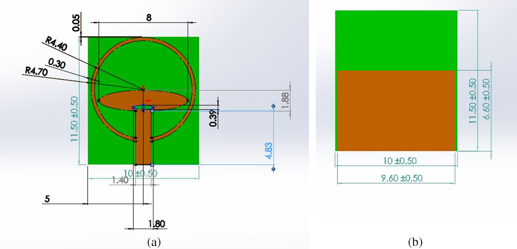
Figure 1: Proposed single element unit cell (a) top view (b) back view
The evolution of the antenna is shown in Fig. 2. The stages shown have a partial ground at the back. The corresponding reflection coefficient is illustrated in Fig. 3. In step 1, an ellipse shaped patch is designed along with the feed line. The structure resonated at 26 GHz with a reflection coefficient better than 15 dB.
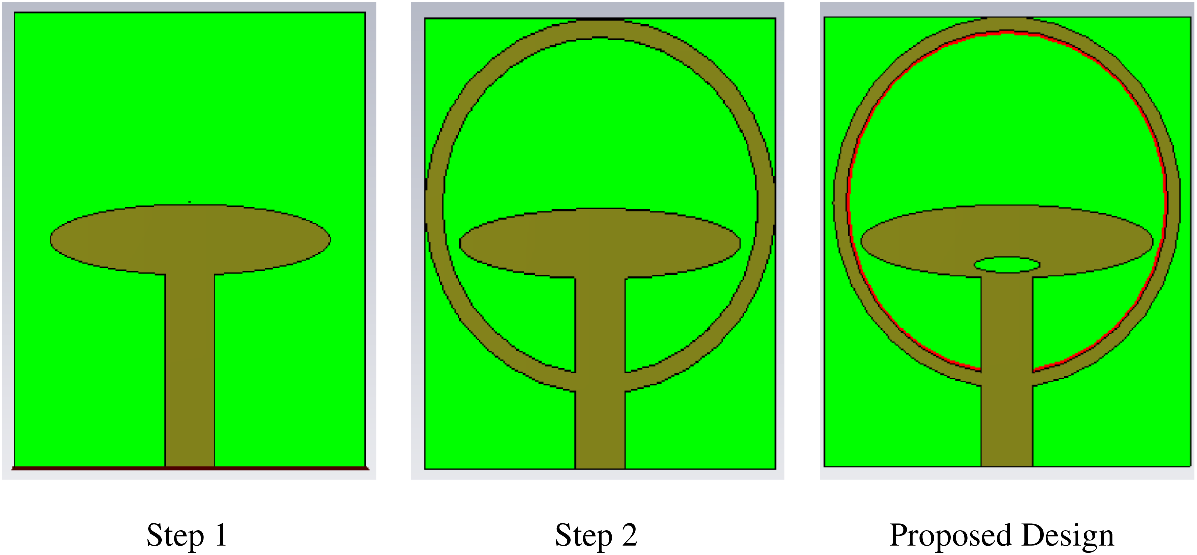
Figure 2: Evolution of the antenna
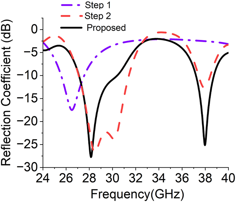
Figure 3: Reflection coefficient comparison at the different stages of the antenna design
To achieve the desired goal for the proposed model, a hollow circle is created housing the ellipse and feed line that leads to dual-band performance (step 2).
From Fig. 3, it is visualized that the proposed antenna resonates at 28 GHz with fractional bandwidth of 15.2% (27.15.12–31.42 GHz) and 38 GHz with fractional bandwidth of 2.7% (37.48–38.51 GHz) having a return loss of 37 and 13 dB, respectively. However, the return loss is very low at 38 GHz. However, the return loss is very low at 38 GHz hence, to improve it, there is a center oval patch truncated by the other small oval as shown in Fig. 3 that generates the capacitive reactance. The creation of an oval slot improves the performance of S11 at 38 GHz which is shown in Fig. 3. It was ensured that performance at 28 GHz does not deteriorate. The proposed antenna now effectively radiates at dual resonant bands with better than 20 dB return loss.
Fig. 4 shows the surface current distribution on the proposed antenna at dual bands. From Figs. 4a and 4b, the current distribution indicates that the proposed geometry effectively radiates at 28 and 38 GHz.
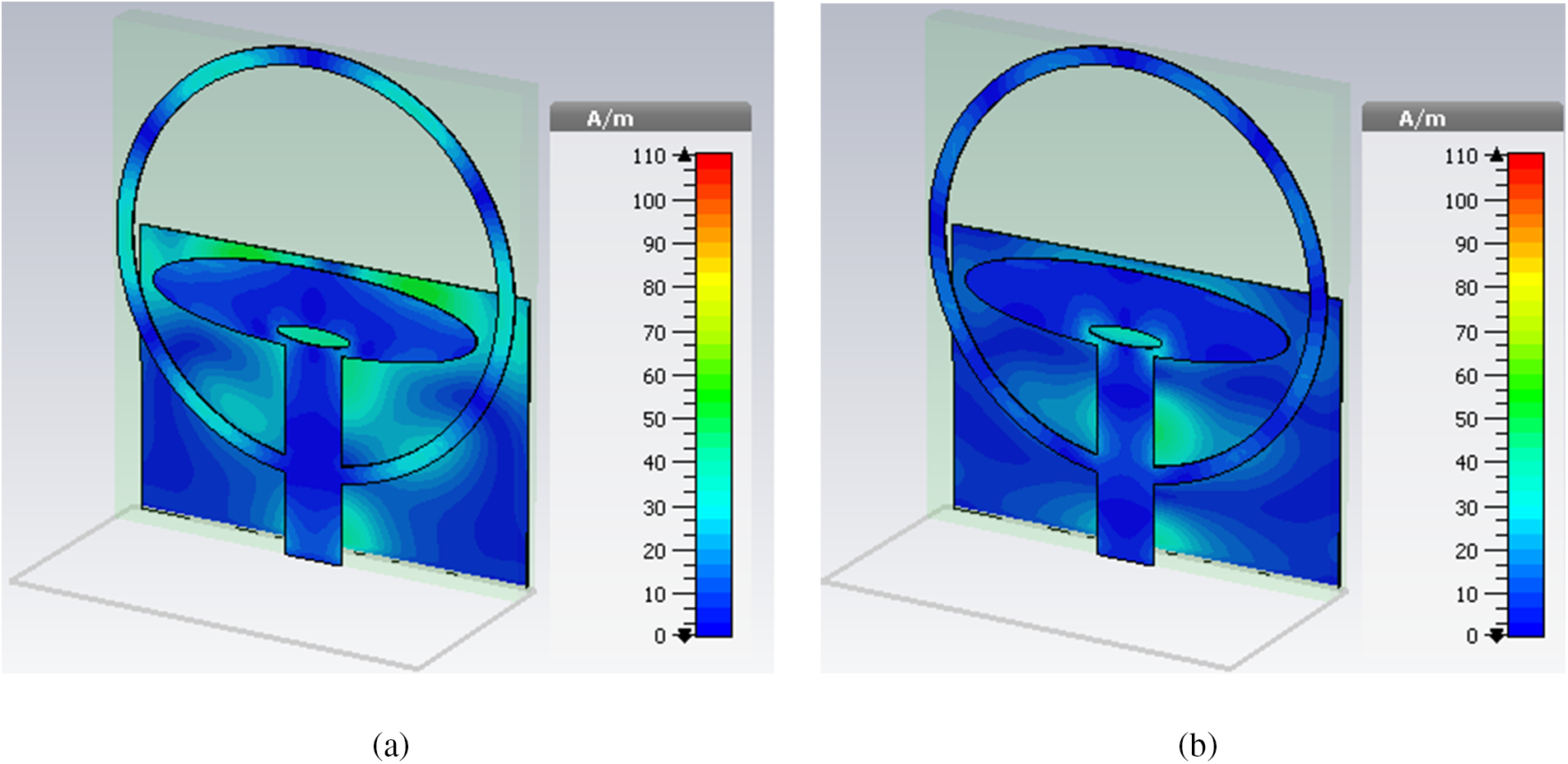
Figure 4: Surface current distribution at (a) 28 GHz and (b) 38 GHz
2.2 Four-Element MIMO Antenna System (without Common Ground)
To configure the unit element for the MIMO applications, it is desired to keep all the elements of the array in the same plane. Here, a MIMO resonator is attained by orthogonal rotation of the single element in the clockwise direction as illustrated in Fig. 5. The top view and the bottom view of the proposed antenna with separate ground are shown in Figs. 5a and 5b, respectively.
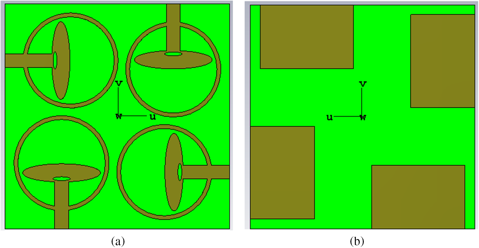
Figure 5: 2 × 2 array antenna (a) top view (b) bottom view
To get minimum coupling between inter-elements, it is recommended to keep a distance between elements of at least λ/2. The current flow on the surface of the array antenna is shown in Fig. 6 for the operating frequencies 28 and 38 GHz where very less coupling is observed amid the elements. The S-parameters of the resonator are shown in Fig. 6. It indicates that the isolation between the elements is better than 15 dB. However, to integrate the devices, it is desired to have a common ground between all the elements [14].
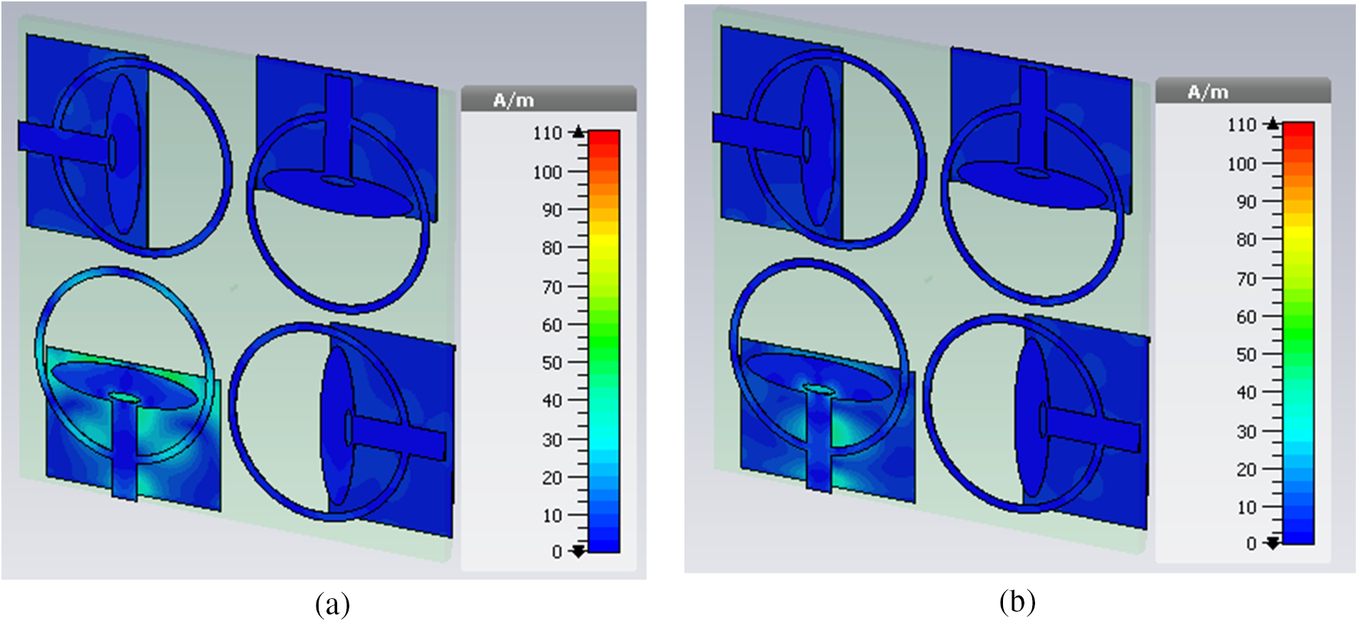
Figure 6: Surface current distribution on 2 × 2 proposed antenna at (a) 28 GHz and (b) 38 GHz
2.3 Four-Element MIMO Antenna System (Common Ground)
From the previous section, it is observed that separate ground antenna helps in achieving higher isolation however as discussed previously, the connected ground antennas are the more preferred choice for MIMO applications. So, in Fig. 7, the 4-port MIMO antenna system’s front view, bottom view, and perspective view are shown. To give common ground, square-shaped stubs are added to connect the partial ground plane.
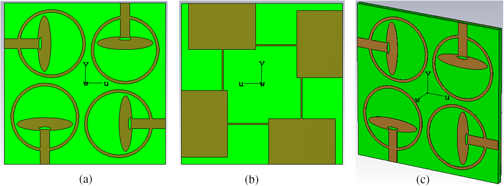
Figure 7: (a) Front view (b) Bottom view (c) Perspective view
Fig. 8 shows the current flow on the proposed antenna at 28 and 38 GHz while exciting port 1. It represents that the proposed antenna effectively radiates the power at both the bands and also the coupling current is very less although the ground is common in the design, which is a prime requirement in several applications.

Figure 8: The surface current flow of a four-element antenna system with the common ground at (a) 28 GHz and (b) 38 GHz
The transmission parameters for the 4-port antenna system are shown in Fig. 9. It indicates that the isolation amongst the elements at both the operating bands is better than 15 dB while the impedance bandwidth of the antenna is unaffected. Hence, it has strong isolation between the elements, and decent IBW for both the bands and individual elements can operate independently without affecting the performance of each other.
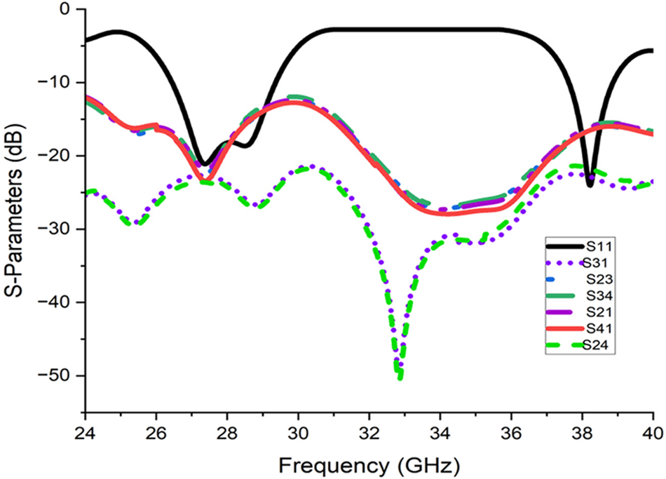
Figure 9: S-parameters of the proposed 4-element antenna with common ground plane
The proposed 4-element MIMO antenna has been fabricated on the RT duroid 5880 having a thickness of 0.8 mm. The top view and bottom view of the fabricated structure are shown in Figs. 10a and 10b, respectively. ZVA50 Vector network analyzer (VNA) is used to measure the reflection coefficient of the proposed antenna. The experimental results are shown in Fig. 11 which is compared with the simulated ones. A small deviation in the measured result is observed which could be due to fabrication tolerances and the soldering of the connector that may change the impedance since at millimeter wavelength high accuracy is required.
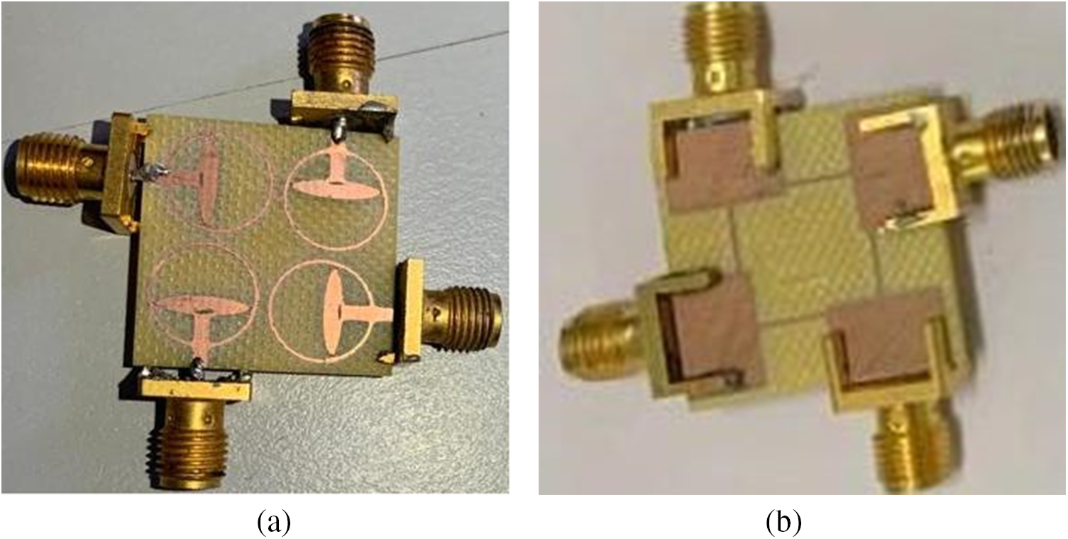
Figure 10: Fabricated four-element MIMO antenna (a) front view and (b) back view
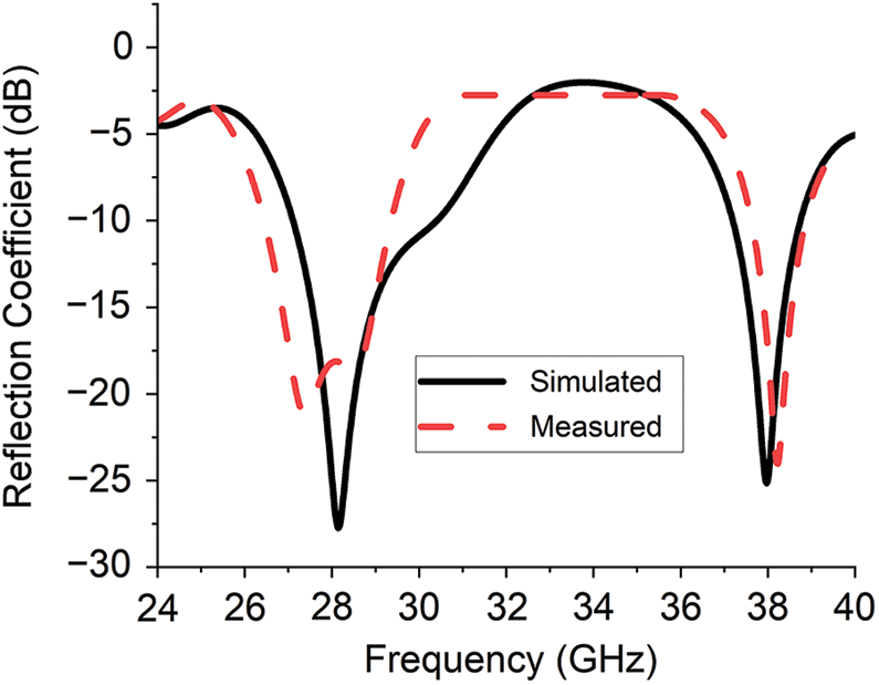
Figure 11: Simulated and measured reflection coefficient of the proposed antenna
The co/cross-pol radiation pattern (in E-plane and H-plane) of the proposed antenna is measured using the setup shown in Fig. 12. The single element of a 4-port MIMO is excited with a source and terminating other elements with matched load, the radiation pattern of the antenna has been measured in both planes. From Fig. 13, it is clear that the proposed antenna gives good isolation between Co-pol and Cross-pol components at both bands.
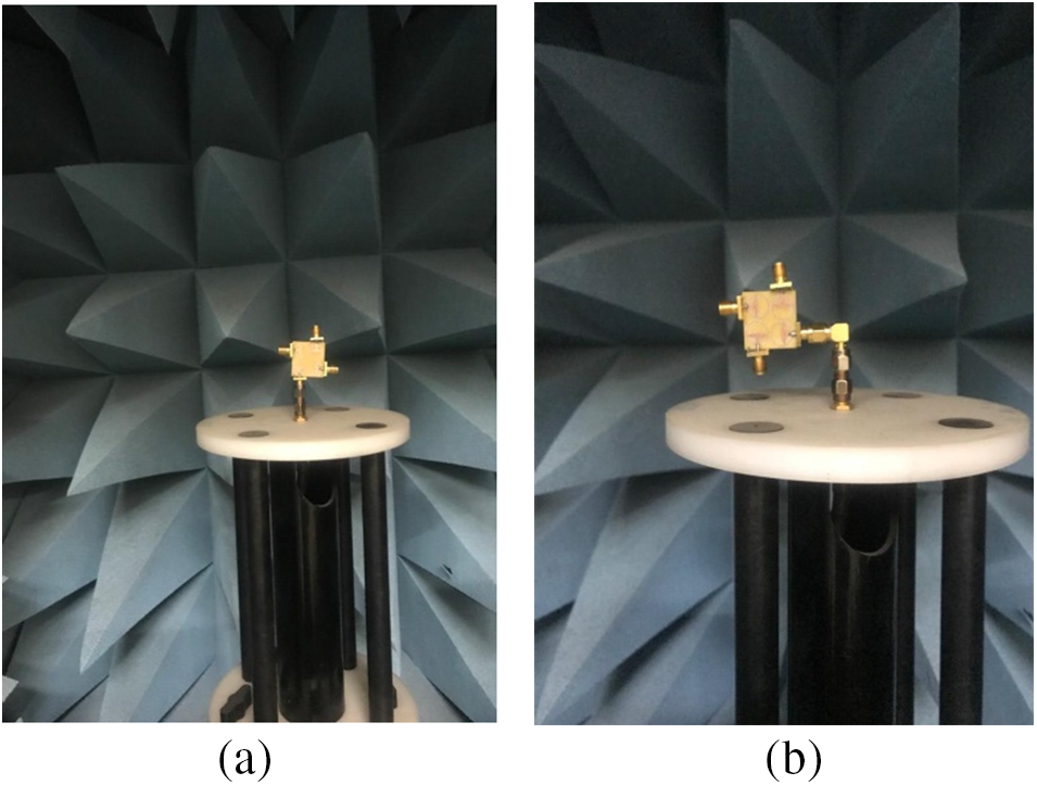
Figure 12: Set-up for radiation pattern measurement in (a) E-plane and (b) H-plane
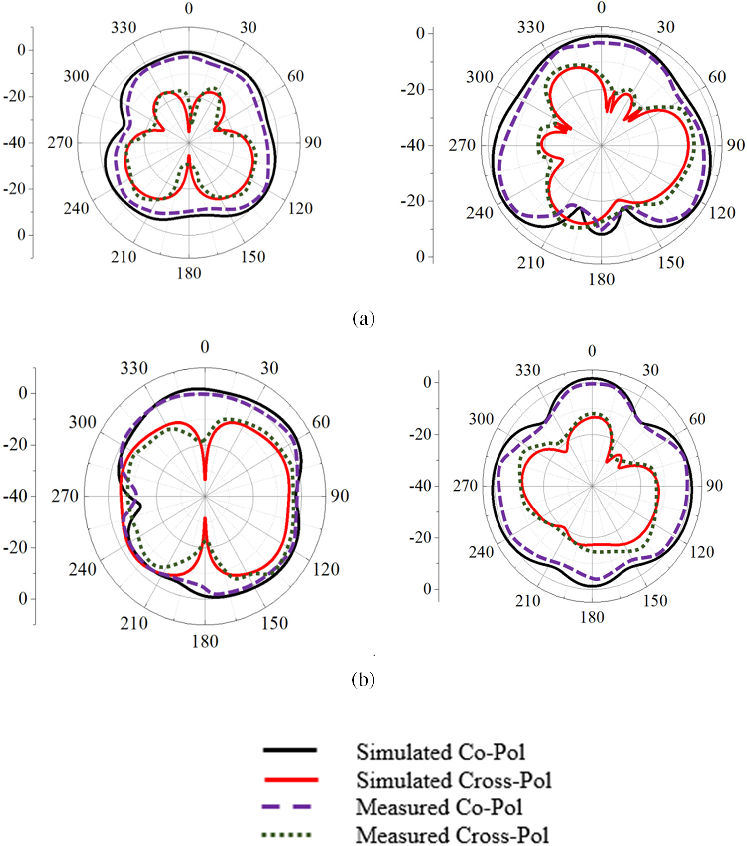
Figure 13: Simulated and measured results of co-pol and cross-pol at (a) 28 GHz and (b) 38 GHz
To find the correlation between the elements in the 2 × 2 array antenna, the proposed antenna is evaluated using key factors known as the ECC and DG. The role of ECC is to quantify the channel quality in a wireless medium where lower ECC gives a guarantee for higher isolation. The ECC of the antenna is calculated from the far-field parameter equation referring to Eq. (1) [17,18].
In the Eq. (1), E1 and E2 are the radiated field (3D) of antennas. Both the measured and simulated results of the ECC are shown in Fig. 14. It shows that the ECC is well below 0.04, which is desired. Another important factor is DG and it is represented by using the Eq. (2). It is derived from the ECC, therefore it is shown with ECC in the same figure.
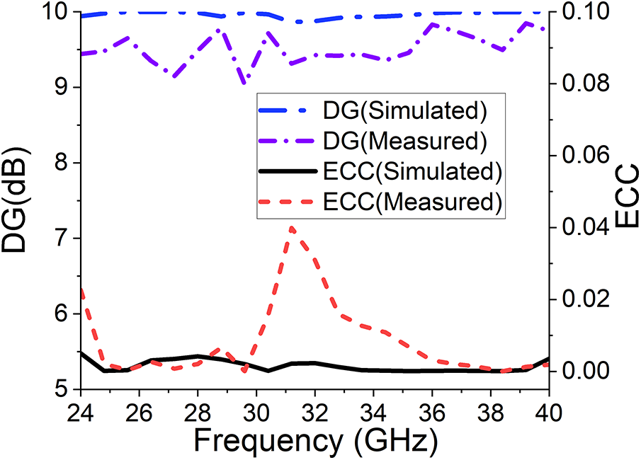
Figure 14: ECC and diversity gain performance over the operating band
The diversity gain is greater than 9.5 dB over the dual bands (28 and 38 GHz). Based on both ECC and DG values, it is ensured that the proposed model of a 2 × 2 array antenna can be used in MIMO applications.
Fig. 15 shows the simulated and measured results of the gain with the simulated efficiency of the proposed antenna. The antenna depicted more than 5.6 dBi gain and over 85% radiation efficiency in the desired band proving the utilization of the antenna for MIMO applications.
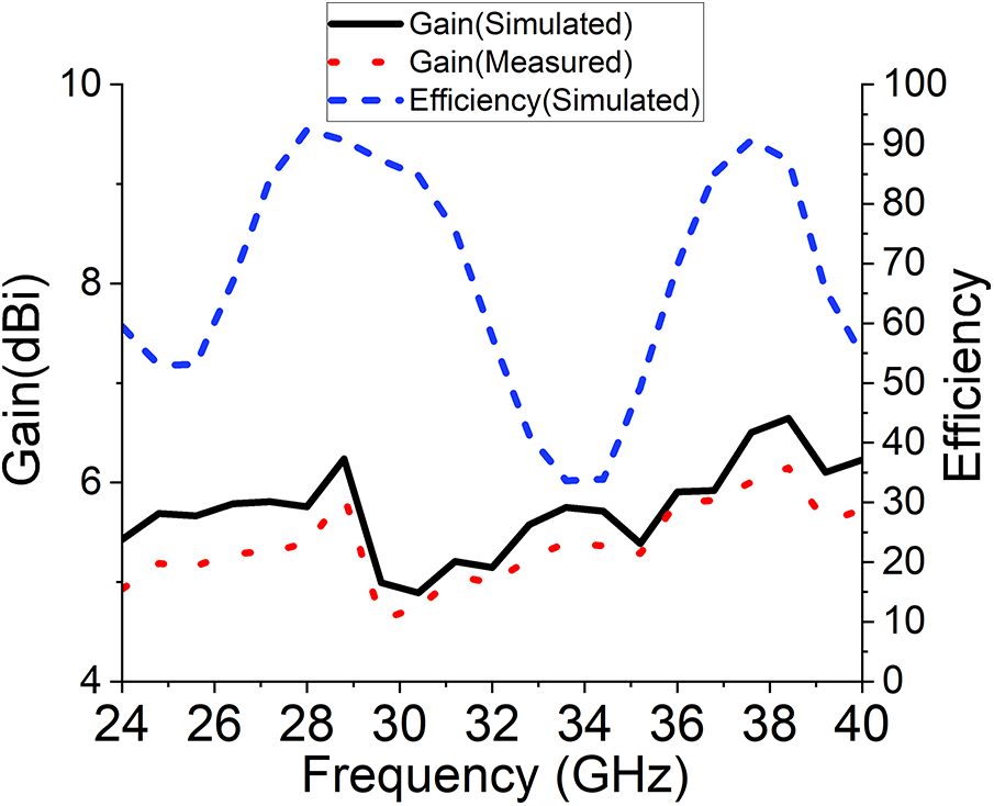
Figure 15: Gain and efficiency plot over the frequency band
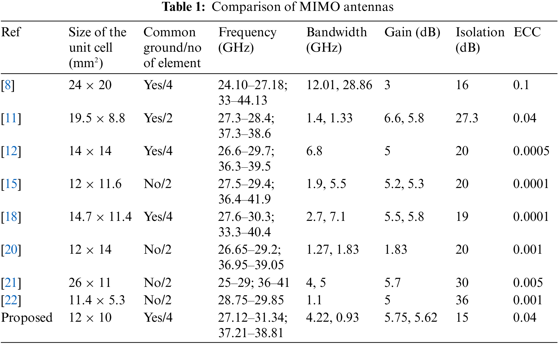
Here, some of the MIMO antennas [8,11,12,14,15,18–20] based on the physical dimensions and electrical parameters (like area of the antenna, operating bandwidth, gain, isolation, and radiation efficiency) have been chosen for comparison with the proposed antenna which are mentioned in Table 1. From Table 1, it is established that the proposed antenna is smaller in size and has a better operating bandwidth in the bands, with higher gain. The antenna in [20] has a lower size however it is only proposed for 2-element MIMO and a single operating band.
A compact (2.24λ × 2.24λ) 4-port MIMO antenna having a slotted ellipse and feed line enclosed within a hollow circular structure is proposed. The proposed antenna is radiating at 28 and 38 GHz bands with reflection coefficient and gain better than 25 and 6 dB, respectively. Moreover, the isolation between individual elements with the common ground is better than 15 dB. The simulated and measured results matched well with each other except for a small variation due to fabrication tolerance that proves the suitability of the proposed antenna for millimeter-wave 5G applications.
Funding Statement: This work is supported by the Moore4Medical Project, funded within ECSEL JU in collaboration with the EU H2020 Framework Programme (H2020/2014-2020) under Grant Agreement H2020-ECSEL-2019-IA-876190, and Fundação para a Ciência e Tecnologia (ECSEL/0006/2019). This work is also funded by the FCT/MEC through national funds and when applicable co-financed by the ERDF, under the PT2020 Partnership Agreement under the UID/EEA/50008/2020 Project.
Conflicts of Interest: The authors declare that they have no conflicts of interest to report regarding the present study.
References
1. Muhammad, S., Yaro, A. S., Yaâ, I., Salawudeen, A. T. (2019). Design of 5G mobile millimeter wave antenna. ATBU Journal of Science, Technology and Education, 7(2), 178–184. [Google Scholar]
2. Patel, A., Vala, A., Desai, A., Elfergani, I., Mewada, H. et al. (2022). Inverted-L shaped wideband MIMO antenna for millimeter-wave 5G applications. Electronics, 11(9), 1387. https://doi.org/10.3390/electronics11091387 [Google Scholar] [CrossRef]
3. Patel, A., Desai, A., Elfergani, I., Vala, A., Mewada, H. et al. (2022). UWB CPW fed 4-port connected ground MIMO antenna for sub-millimeter-wave 5G applications. Alexandria Engineering Journal, 61(9), 6645–6658. https://doi.org/10.1016/j.aej.2021.12.015 [Google Scholar] [CrossRef]
4. Abirami, M. (2017). A review of patch antenna design for 5G. 2017 IEEE International Conference on Electrical, Instrumentation and Communication Engineering, pp. 1–3. Karur, India. https://doi.org/10.1109/ICEICE.2017.8191842 [Google Scholar] [CrossRef]
5. Haraz, O. M. (2016). Broadband and 28/38-GHz dual-band printed monopole/elliptical slot ring antennas for the future 5G cellular communications. Journal of Infrared, Millimeter, and Terahertz Waves, 37(4), 308–317. https://doi.org/10.1007/s10762-016-0252-2 [Google Scholar] [CrossRef]
6. Dzagbletey, P. A., Jung, Y. B. (2018). Stacked microstrip linear array for millimeter-wave 5G baseband communication. IEEE Antennas and Wireless Propagation Letters, 17(5), 780–783. https://doi.org/10.1109/LAWP.2018.2816258 [Google Scholar] [CrossRef]
7. Ancans, G., Bobrovs, V., Ancans, A., Kalibatiene, D. (2017). Spectrum considerations for 5G mobile communication systems. Procedia Computer Science, 104(3), 509–516. https://doi.org/10.1016/j.procs.2017.01.166 [Google Scholar] [CrossRef]
8. Desai, A., Bui, C. D., Patel, J., Upadhyaya, T., Byun, G. et al. (2020). Compact wideband four element optically transparent MIMO antenna for mm-wave 5G applications. IEEE Access, 8, 194206–194217. https://doi.org/10.1109/ACCESS.2020.3033314 [Google Scholar] [CrossRef]
9. Kornprobst, J., Wang, K., Hamberger, G., Eibert, T. F. (2017). A mm-wave patch antenna with broad bandwidth and a wide angular range. IEEE Transactions on Antennas and Propagation, 65(8), 4293–4298. https://doi.org/10.1109/TAP.2017.2710261 [Google Scholar] [CrossRef]
10. Mahmoud, K. R., Montaser, A. M. (2018). Performance of tri-band multi-polarized array antenna for 5G mobile base station adopting polarization and directivity control. IEEE Access, 6, 8682–8694. https://doi.org/10.1109/ACCESS.2018.2805802 [Google Scholar] [CrossRef]
11. Farahat, A. E., Hussein, K. F. (2022). Dual-band (28/38 GHz) wideband MIMO antenna for 5G mobile applications. IEEE Access, 10, 32213–32223. https://doi.org/10.1109/ACCESS.2022.3160724 [Google Scholar] [CrossRef]
12. Khabba, A., Amadid, J., Ibnyaich, S., Zeroual, A. (2022). Pretty-small four-port dual-wideband 28/38 GHz MIMO antenna with robust isolation and high diversity performance for millimeter-wave 5G wireless systems. Analog Integrated Circuits and Signal Processing, 112(1), 83–102. https://doi.org/10.1007/s10470-022-02045-8 [Google Scholar] [CrossRef]
13. Liu, F., Guo, J., Zhao, L., Huang, G. L., Li, Y. et al. (2020). Ceramic superstrate-based decoupling method for two closely packed antennas with cross-polarization suppression. IEEE Transactions on Antennas and Propagation, 69(3), 1751–1756. [Google Scholar]
14. Sharawi, M. S. (2017). Current misuses and future prospects for printed multiple-input, multiple-output antenna systems [wireless corner]. IEEE Antennas and Propagation Magazine, 59(2), 162–170. https://doi.org/10.1109/MAP.2017.2658346 [Google Scholar] [CrossRef]
15. Sabek, A. R., Ali, W. A. E., Ibrahim, A. A. (2022). Minimally coupled two-element MIMO antenna with dual band (28/38 GHz) for 5G wireless communications. Journal of Infrared, Millimeter, and Terahertz Waves, 43, 335–348. https://doi.org/10.1007/s10762-022-00857-3 [Google Scholar] [CrossRef]
16. Tsao, Y. F., Desai, A., Hsu, H. T. (2022). Dual-band and dual-polarization CPW Fed MIMO antenna for fifth-generation mobile communications technology at 28 and 38 GHz. IEEE Access, 10, 46853–46863. https://doi.org/10.1109/ACCESS.2022.3171248 [Google Scholar] [CrossRef]
17. Liu, F., Guo, J., Zhao, L., Huang, G. L., Li, Y. et al. (2019). Dual-band metasurface-based decoupling method for two closely packed dual-band antennas. IEEE Transactions on Antennas and Propagation, 68(1), 552–557. [Google Scholar]
18. Sharawi, M. S. (2013). Printed multi-band MIMO antenna systems and their performance metrics [wireless corner]. IEEE Antennas and Propagation Magazine, 55(5), 218–232. https://doi.org/10.1109/MAP.2013.6735522 [Google Scholar] [CrossRef]
19. Addepalli, T., Desai, A., Elfergani, I., Anveshkumar, N., Kulkarni, J. et al. (2021). 8-port semi-circular arc MIMO antenna with an inverted L-strip loaded connected ground for UWB applications. Electronics, 10(12), 1476. https://doi.org/10.3390/electronics10121476 [Google Scholar] [CrossRef]
20. Hasan, M. N., Bashir, S., Chu, S. (2019). Dual band omnidirectional millimeter wave antenna for 5G communications. Journal of Electromagnetic Waves and Applications, 33(12), 1581–1590. https://doi.org/10.1080/09205071.2019.1617790 [Google Scholar] [CrossRef]
21. Ali, W., Das, S., Medkour, H., Lakrit, S. (2021). Planar dual-band 27/39 GHz millimeter-wave MIMO antenna for 5G applications. Microsystem Technologies, 27(1), 283–292. https://doi.org/10.1007/s00542-020-04951-1 [Google Scholar] [CrossRef]
22. Ahmad, A., Choi, D. Y., Ullah, S. (2022). A compact two elements MIMO antenna for 5G communication. Scientific Reports, 12(1), 1–8. https://doi.org/10.1038/s41598-022-07579-5 [Google Scholar] [PubMed] [CrossRef]
Cite This Article
 Copyright © 2023 The Author(s). Published by Tech Science Press.
This work is licensed under a Creative Commons Attribution 4.0 International License , which permits unrestricted use, distribution, and reproduction in any medium, provided the original work is properly cited.
 Downloads
 Citation Tools