
 Submit a Paper
 Propose a Special lssue
 Open Access
ARTICLE
A Stroke-Limitation AMD Control System with Variable Gain and Limited Area for High-Rise Buildings
1 School of Civil and Environmental Engineering, Harbin Institute of Technology (Shenzhen), Shenzhen, 518055, China
2 Department of Civil and Environmental Engineering, The Hong Kong Polytechnic University, Hong Kong, 100872, China
* Corresponding Authors: Qing-Gui Wu. Email: ; Jun Teng. Email:
(This article belongs to the Special Issue: Computer-Aided Uncertainty Modeling and Reliability Evaluation for Complex Engineering Structures)
Computer Modeling in Engineering & Sciences 2024, 138(1), 865-884. https://doi.org/10.32604/cmes.2023.029927
Received 15 March 2023; Accepted 26 April 2023; Issue published 22 September 2023
 View Full Text
 Download PDF
Abstract
Collisions between a moving mass and an anti-collision device increase structural responses and threaten structural safety. An active mass damper (AMD) with stroke limitations is often used to avoid collisions. However, a stroke-limited AMD control system with a fixed limited area shortens the available AMD stroke and leads to significant control power. To solve this problem, the design approach with variable gain and limited area (VGLA) is proposed in this study. First, the boundary of variable-limited areas is calculated based on the real-time status of the moving mass. The variable gain (VG) expression at the variable limited area is deduced by considering the saturation of AMD stroke. Then, numerical simulations of a stroke-limited AMD control system with VGLA are conducted on a high-rise building structure. These numerical simulations show that the proposed approach has superior stroke-limitation performance compared with a stroke-limited AMD control system with a fixed limited area. Finally, the proposed approach is validated through experiments on a four-story steel frame.Keywords
Tuned mass dampers (TMDs) [1–9], semi-actively tuned mass dampers (SATMDs) [10–15], active tuned mass dampers (ATMDs), and active mass dampers (AMDs) are often used for engineering vibration control [16–22]. In theory, the control effect of AMD is better than that of the other control systems. However, AMD’s moving mass can experience high speeds during operations, resulting in excessive strokes. In particular, when the moving mass moves rapidly and runs close to the maximum permitted stroke, it may collide with the anti-collision device, thus increasing the structural response and even endangering the safety of the AMD control system and structure. Therefore, it is important to limit moving mass stroke and improve the reliability of AMD control systems.
A vibration control system should exhibit robust performance. For continuous systems, a robust H∞ control method based on linear matrix inequalities (LIM) was proposed [23]. By combining H∞ and H2 control, the active control system of a single-story frame structure is established by considering the interaction between the irregularly controlled structure and foundation. The simulation results illustrate that the control system exhibits robust performance [24]. A pole assignment control algorithm is applied to the vibration control of high-rise structures to ensure the robust performance of the control system [25,26]. Because the gain can determine the control effects and parameters of a control system, some scholars have proposed the saturating control and variable gain (VG) method to improve the control performance effectively. For example, applying a saturating control algorithm based on linear quadratics to an AMD control system can limit the moving mass stroke [27]. To improve the control performance of the control system for high-rise buildings, an optimal design considering the saturation of actuators and stroke limitations was proposed [28]. A control system with a VG was established using linear control theory, and the optimal gain was selected by solving inequality problems to achieve the optimal control force [29]. An active vibration control method with variable gain (VG) control was proposed for high-rise buildings under wind load or earthquake action [30]. Variable gain-based structural control was used to control civil engineering structures in the case of earthquakes [31]. The AMD control method of VG was proposed, and the gain matrix was calculated using a linear quadratic regulator (LQR) control algorithm. The relative optimal weight matrix within the specified range was selected based on the magnitude of external excitation to obtain the optimal feedback gain matrix [32]. An algorithm of VG for the stroke-limitation control system was designed, and the design was verified by conducting an experiment [33]. The algorithm of VG with a fixed and limited area requires a large external energy supply. Its limit mechanism still needs improvement to enhance the stroke-limited performance and further avoid the collisions of AMD, ensuring the safe operation of AMD.
To reduce the influence of stroke limitations on the performance of AMD control systems, a stroke-limited AMD control system with variable gain and limited area (VGLA) was proposed in this study. The running states of the VGLA control system are divided into unlimited and variable-limited areas, and the control gain is calculated using an algorithm with H∞/H2 and pole assignment constraints. The deceleration mechanism of the moving mass is determined based on the control force and maximum stroke. Then, based on the real-time states of the moving mass, the gain expression in the variable limited area was deduced considering the saturation of the AMD stroke. Furthermore, numerical simulations were conducted using a stroke-limited AMD control system. Finally, the effectiveness of the proposed methodology was verified by conducting an experiment with a four-story steel frame structure.
2 The Stroke-Limitation Principle of AMD with VGLA
The main objective of structural control is to reduce the acceleration response of buildings to a comfortable level. An AMD device is commonly installed on the structure, as shown in Fig. 1. Under control force u, the building structure vibrations caused by external forces W can be significantly reduced.
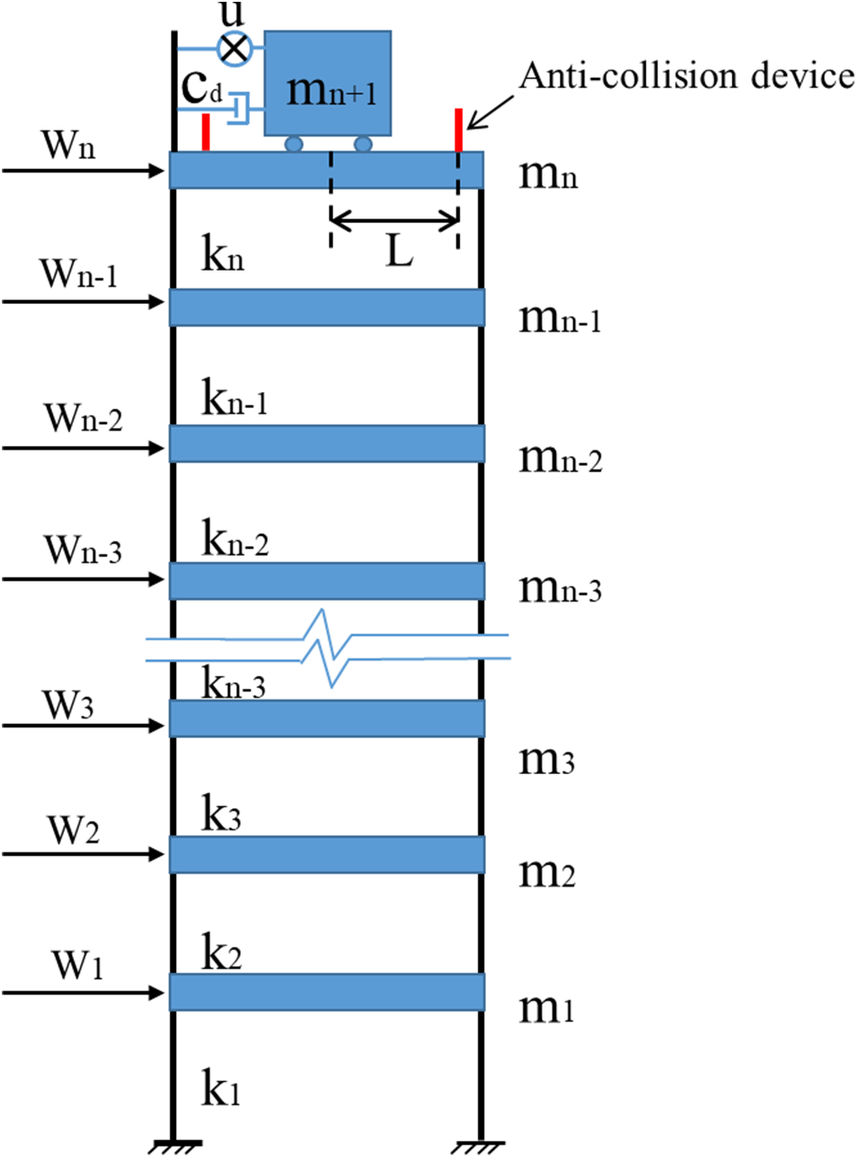
Figure 1: Building structure equipped with AMD
The running states of AMD are divided into eight states, as shown in Fig. 2; the AMD can run freely during running states 1, 4, 5, and 8. When the moving mass is in a limited area and moves toward the equilibrium position (running states 3 and 7, as illustrated in Fig. 2), there is no need to limit the stroke. However, the moving mass may collide with the anti-collision device during running states 2 and 6, thus reducing the control performance and even endangering the safety of AMD. Therefore, to ensure AMD’s safety and high control performance, it is critical to optimize the stroke-limitation strategy during running states 2 and 6.
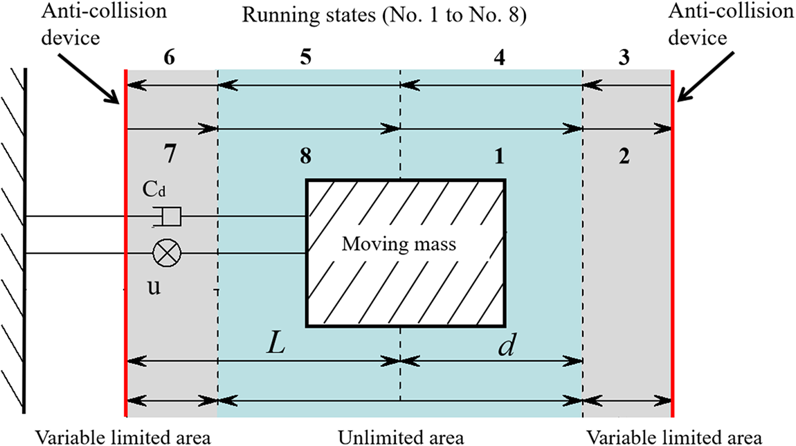
Figure 2: The AMD operation diagram
The force equilibrium of an AMD model (Fig. 1) with uncertain mass and stiffness is
where M, C, and K represent the nominal mass, damping, and stiffness matrices of the system, respectively; ∆M and ∆K represent the uncertain quantities of the mass and stiffness matrices, respectively; X(t) represents the displacement vector; Bs and Bw represent the position matrices of the control forces and excitations, respectively; and u(t) and w(t) represent the control force vector and external excitation vector, respectively.
Matrices ∆K, ∆M, Bs, and Bw are described as follows:
Matrices M, C, K, and X(t) are described as follows:
Assuming that the state vectors are
Matrices C1, C2, D11, D12, D21, and D22 are described as follows:
Based on reference [34], the AMD control force is obtained using the following equation:
where ui(t) denotes the component of the force and G denotes the feedback gain of the AMD.
It is assumed that the matrix of uncertain parameters of structural parameters is
Substituting Eqs. (6) and (7) into Eq. (4), the AMD control system is expressed as follows:
Based on reference [35], the H2 control law with state feedback can be expressed as follows:
Based on reference [36], the H∞ control law with state feedback can be expressed as follows:
Based on reference [37], the performance requirements for regional pole placement can be expressed as follows:
This problem can be solved by finding a common Lyapunov matrix, denoted as X, that satisfies a set of linear matrix inequalities (9)–(11):
To solve this multi-objective control problem, the following convex optimization problem is required:
where
The state feedback controller design method has H2/H∞ performance requirements and closed-loop region pole constraints, which are solved using LMI techniques. Let
The gain of the AMD control system is expressed as follows:
where ga, gn, and gn+1 denote the gains based on the displacement of the floor in which the AMD is installed, the top floor, and AMD, respectively.
When AMD runs into a variable-limited area, as shown in Fig. 3, the displacement of the floor with AMD and moving mass must be calculated in real time to determine the gains and control forces. Because the building structure has many degrees of freedom, the displacement of the other floors is not considered when calculating the control force, which reduces the computation. Then, the control forces are expressed as follows:
where za denotes the displacement of the floor where the AMD is installed and zn+1 denotes the displacement of the AMD.

Figure 3: The curve of the stroke-limitation mechanism
Assuming that ga = −gn+1, then
where x(t) is the stroke of the moving mass and x(t) > 0.
Based on Eq. (17), we have
From Eq. (17), if gn+1 > 0, the control force at the variable-limited area has the opposite sign to x(t). When the AMD runs into a variable limited-area, the moving mass is subjected to braking force
Based on Eqs. (15)–(18), the gain of the AMD control system is expressed as follows:
When the AMD runs into the variable limited area (the shadow area shown in Fig. 3), the gain at the variable-limited area is calculated by considering the maximum allowable stroke L and the real-time velocity of moving mass Vd. If AMD is not in a variable-limited area, the gain of the AMD control system is calculated using the regional pole-assignment algorithm.
In the variable-limited area, the velocity of the moving mass decreases. When the stroke of the moving mass reaches L, its velocity is zero (Fig. 3). The moving mass’s velocity in a variable limited area is
where x(t), L, and Fmax denote the stroke of the moving mass, the maximum allowable stroke, and the control force of the AMD control system, respectively. Vd denotes the real-time velocity of the moving mass at the boundaries of a variable-limited area. The accelerations can be determined by differentiating the velocity of the moving mass as follows:
The expected control forces are
Substituting Eq. (19)–(22) into Eq. (18), the gain is based on the displacement of the floor where AMD is installed and the moving mass is
3 Numerical Simulation of an AMD Control System Using VGLA
3.1 Modeling of the AMD Control System Using VGLA
The high-rise building named KingKey Financial Center in Shenzhen, shown in Fig. 4a, has 100 floors above the ground and four floors underground. The height above the ground is 441.8 m, and their structural modal parameters are listed in Table 1. The AMD control system depicted in Figs. 4b and 4c includes two AMD control systems. The AMD’s control parameters are listed in Table 2. When the moving mass is in an unlimited area. The control forces can be represented by Eq. (14). The VGLA control system with stroke limitations is illustrated using a Simulink block diagram (Fig. 5).
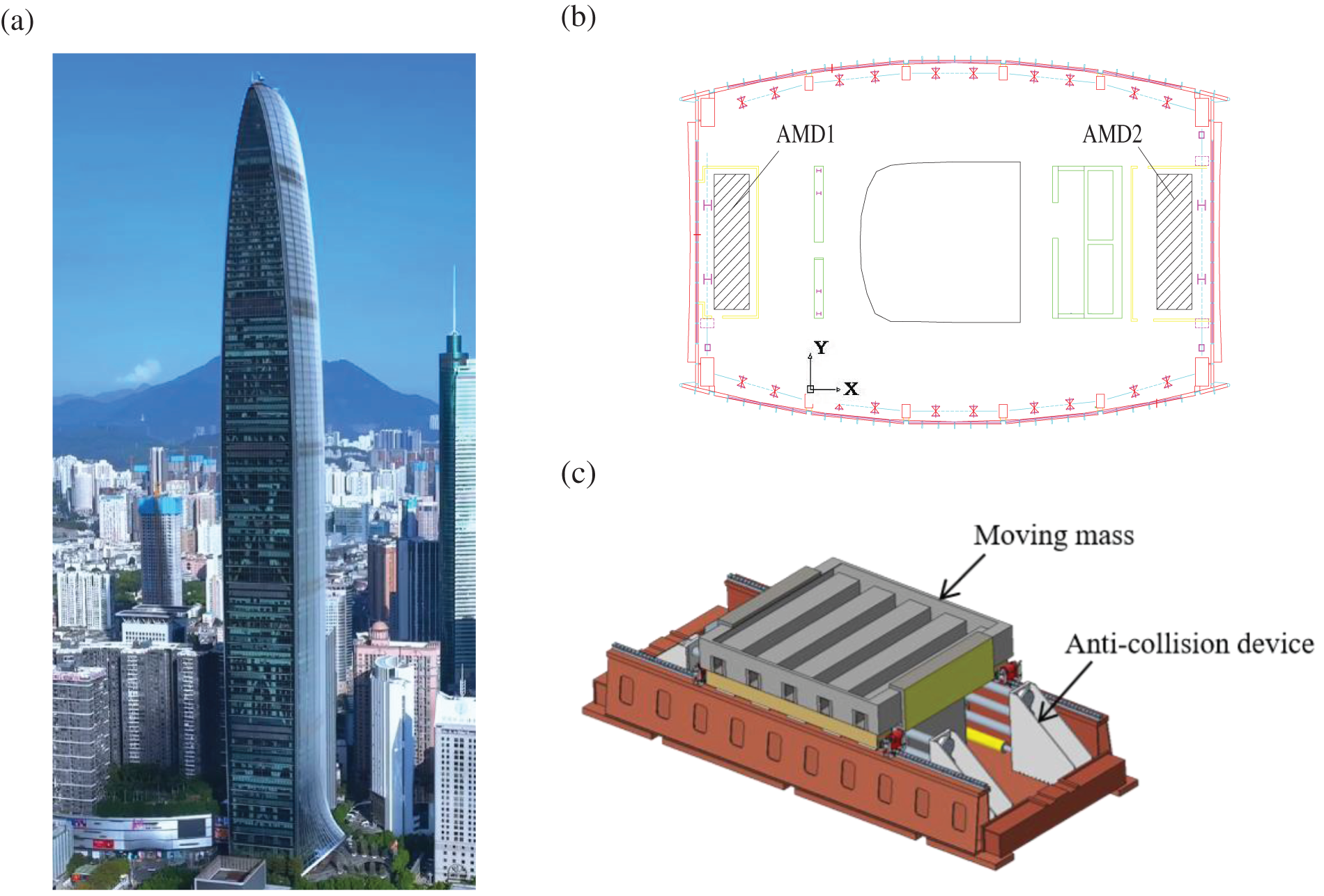
Figure 4: The high-rise building and AMD control system. (a) The high-rise building; (b) The installation position of AMD; (c) AMD control system
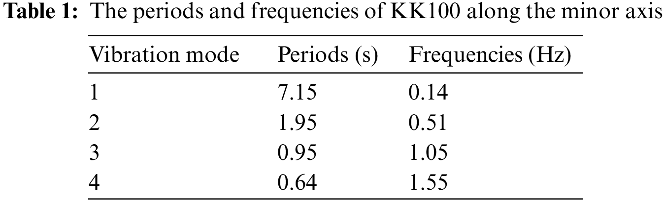
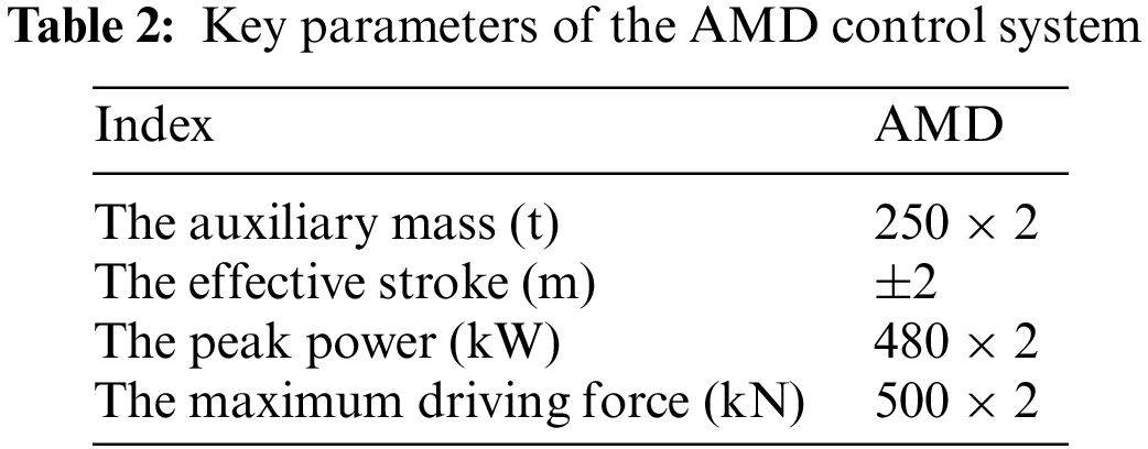

Figure 5: Simulink module of the stroke-limitation control system of VGLA
The Simulink block diagram shown in Fig. 5 can be used to depict a VGLA system with stroke limitations. The 10-year return period fluctuating wind speed is based on the Davenport spectrum, and a mixed auto-regressive moving average model is used to simulate its stochastic process [38]. The fluctuating wind load of the ith floor is calculated using the following equation [33]:
To verify and compare the control performance of the VGLA, the method of stroke-limited AMD control system with VG in reference [33] is analyzed. The VG velocities of the moving mass in a fixed limited area are calculated using Eq. (25) (Fig. 6). The VG gain of the moving mass in a fixed limited area is calculated using Eq. (26). Its fixed boundary of fixed limited area, d is 1.5 m.

Figure 6: The curve of the stroke-limitation mechanism of the VG control system
3.2 Simulation Results for VG and VGLA
Fig. 7 and Table 3 show that AMD without stroke limitations can effectively suppress the dynamic response of the structure. The VG, VGLA, and AMD control systems without stroke limitations have the same displacement and acceleration control effects. When the stroke of the moving mass exceeds 1.5 m, the control force and power of the VG increase rapidly (Figs. 7e, 7f, 7i, and 7j). In particular, as demonstrated in Fig. 7i, when the moving mass of the VG control system enters a fixed limited area, it moves rapidly. It is subjected to a large braking force, resulting in a sudden increase in power to 1459 kW.


Figure 7: The top floor’s responses and the AMD parameters
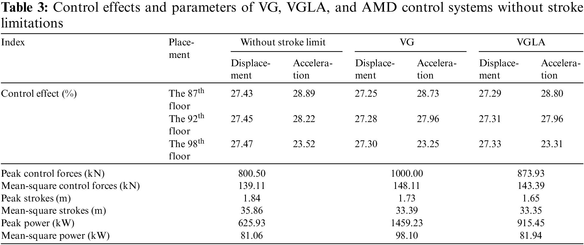
Furthermore, the peak stroke of the VG is 1.73 m, and the peak stroke of VGLA is 1.65 m. The peak stroke of VG is 5.98% lower than that of the AMD system without stroke limitations. The peak stroke of VGLA is 10.33% lower than that of AMD without stroke limitation. However, the peak control force and power of the VGLA are 12.6% and 37.27% lower than those of the VG, respectively. The mean-square control force and power of the VGLA are 3.20% and 16.47% lower than those of the VG, respectively. Therefore, the control performance of VGLA is significantly better than that of VG.
As shown in Fig. 8, the experimental system comprises a single-span four-story steel frame structure and its control system. The AMD control system mainly comprises a servo driver, control motor, DSPACE of board model DS1103, Ethernet for Control Automation Technology (EtherCAT) bus, and microcomputer. The system is equipped with an EtherCAT bus system composed of an LMCF210201 linear control motor produced by Shenzhen Dazu Laser Company, Guangdong Province, EL3008 input terminal, EL4034 output terminal, and EK1100 coupling terminal; an AX5000 servo driver produced by Beckhoff Company, Germany.


Figure 8: Picture of the AMD experimental system and its schematic diagram
The weak axial displacement and acceleration of the four-floor steel frame structure can be measured by applying the measurement system. The force balance acceleration sensor is used in the system, and the micro-epsilon series laser displacement sensor is used in the system. The structural mass matrix can be obtained using the concentrated mass method. That is, the mass of each floor of the structure is obtained by calculating the geometric size, density, and other parameters of the controlled structure as well as the related parameters of the equipment; the mass matrix is finally combined. The structural stiffness matrix is obtained by utilizing FEM software. The aforementioned components of the AMD control system are shown in Fig. 8.
Table 4 shows that the first two modes of the structure mainly contribute to the dynamic response of the structure because the mass participation coefficient of the first two modes is 0.946, which is approximately 1. The loading frequency of the loading system is 1 Hz. The corresponding peak value of the excitation force is 45.89 N. Under this excitation, the maximum stroke is 0.4 m. Under the action of excitation load, the time-history comparison of the measured displacement and acceleration responses of each floor of the structure is shown in Fig. 9, and the control effects are shown in Table 5.
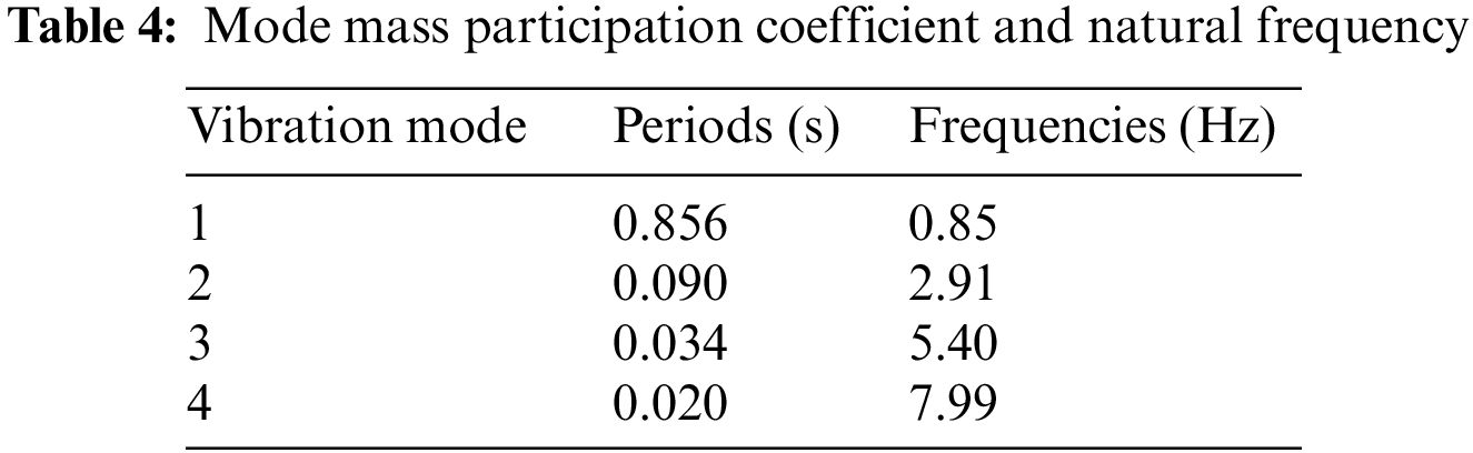
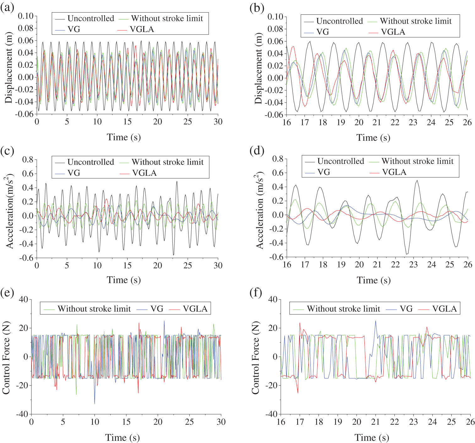

Figure 9: Experimental responses and AMD parameters
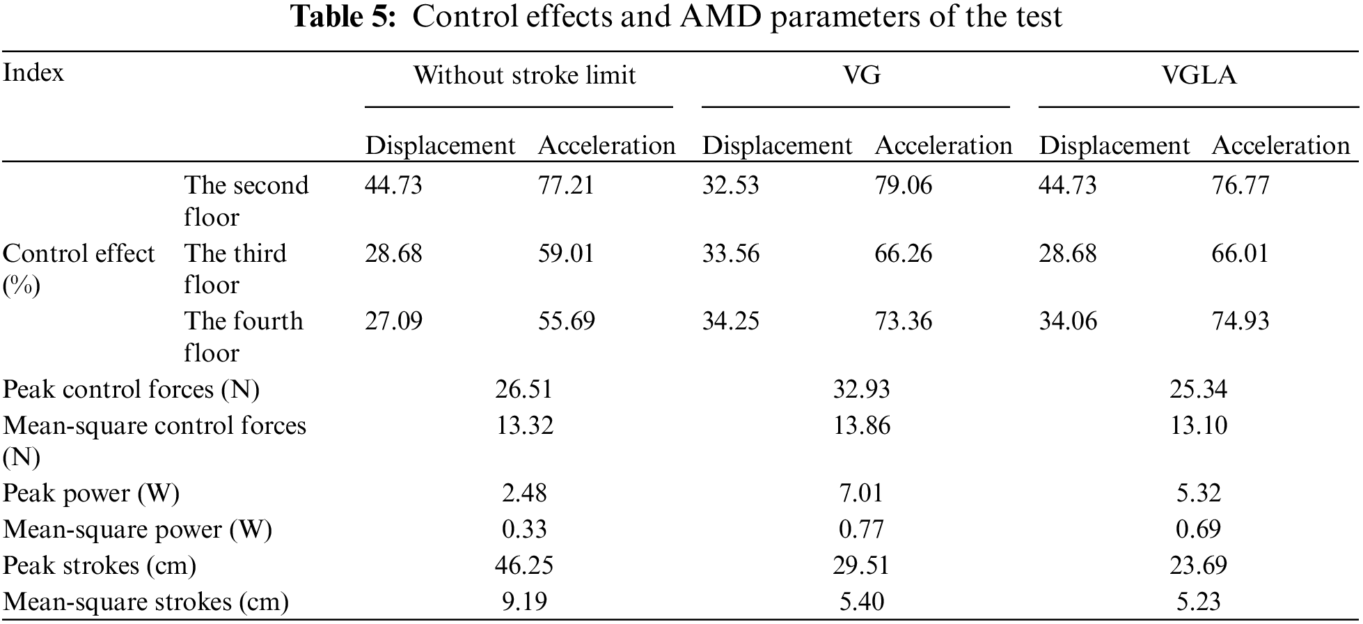
Table 5 and Fig. 9 show that the structural response does not completely obey the sinusoidal variation law because of the interaction between the AMD control system and the structure and the coupling of the horizontal and vertical vibrations of the structure. The control effects of VG and VGLA are higher than that of an AMD without stroke limitations. The reason for this phenomenon is that the stroke of AMD without stroke limitation exceeds the permitted stroke of the control system, and the collision with the anti-collision device reduces its control effects.
The peak stroke of VGLA is 19.72% less than that of VG, but the peak control force and power of VGLA are 23.05% and 24.11% lower than those of VG, respectively. The mean-square stroke of VGLA is 3.15% less than that of VG. However, the mean-square control power of VGLA is 10.40% lower than that of VG. The experimental results agree with the numerical simulation results (Section 3). Therefore, the control performance of VGLA is better than that of the traditional stroke-limitation control method VG. The proposed VGLA method exhibits a good control effect and can significantly decrease the stroke to guarantee the safe operation of the AMD control system.
In order to limit the stroke of the moving mass in the AMD control system, the relation between the stroke and the corresponding feedback gain was established, and the design method of a stroke-limitation system with variable limited area and gain was proposed. Finally, the numerical model of an actual building structure and the experimental model of the four-story frame were taken to verify the necessity and effectiveness of the stroke-limitation system with VGLA. The main conclusions are drawn as follows:
(1) The stroke-limited AMD control system of the VGLA exhibits a good control effect. In a situation where no collision of the control system without stroke limitation occurred, the control effect of the VGLA is approximately equal to that of the control system without stroke limitation. In a situation where a collision of the control system without stroke limitation occurred, the control effects of the VGLA are better than those of the control system without stroke limitation.
(2) The maximum force and stroke of the AMD are considered in the stroke-limitation principle, which can limit the control force and power of the VGLA to permissible ranges.
(3) Considering the variable limited area, the stroke limit effect of VGLA is better than that of VG; however, the control force and power of VGLA are lower than those of VG.
(4) The numerical simulation results agree with the experimental results. The stroke-limitation system with VGLA proposed in this study can effectively limit the stroke to a reasonable range, thus ensuring the control effects and safety of the AMD system.
Based on the variable gain feedback control method, the VGLA method proposed in this paper achieves a stroke limitation control method for building structures with variable-limit areas. The application results show that the proposed method has a short stroke and requires low control power, indicating its potential for effectively controlling structural vibrations in high-rise buildings.
Acknowledgement: The authors would like to thank Houbing Xing for advice on experimental design.
Funding Statement: This research was founded by the Funds for Creative Research Groups of National Natural Science Foundation of China (Grant No. 51921006), the National Natural Science Foundations of China (Grant No. 51978224), the National Major Scientific Research Instrument Development Program of China (Grant No. 51827811), the National Natural Science Foundation of China, (Grant No. 52008141) and the Shenzhen Technology Innovation Program (Grant Nos. JCYJ20170811160003571, JCYJ20180508152238111 and JCYJ20200109112803851).
Author Contributions: Zuohua Li and Qinggui Wu contributed equally to this work. Qinggui Wu wrote the paper and summarized the results. Zuohua Li and Jun Teng participated in the data analysis and conceived the study. Chaojun Chen reviewed the study plan.
Availability of Data and Materials: All data generated and analyzed during this study are included in this published article.
Conflicts of Interest: The authors declare that they have no conflicts of interest to report regarding the present study.
References
1. Kaveh, A., Javadi, S. M., Mahdipour, R. (2020). Optimal structural control of tall buildings using tuned mass dampers via chaotic optimization algorithm. Structures, 28, 2704–2713. [Google Scholar]
2. Fatollahpour, A., Tafakori, E., Ali Asghar Arjmandi, S. (2023). The effects of structure-soil-structure interaction on seismic response of high-rise buildings equipped with optimized tuned mass damper. Structures, 50, 998–1010. [Google Scholar]
3. Saha, A., Mishra, S. K. (2019). Adaptive negative stiffness device based nonconventional tuned mass damper for seismic vibration control of tall buildings. Soil Dynamics and Earthquake Engineering, 126(11), 105767.1–105767.21. [Google Scholar]
4. He, H., Tan, P., Hao, L. (2022). Acceleration-based effective damping ratio of tuned mass damper under seismic excitations. The Structural Design of Tall and Special Buildings, 31(4), e1910.1–e1910.16. [Google Scholar]
5. He, H., Wang, W., Xu, H. (2017). Multidimensional seismic control by tuned mass damper with poles and torsional pendulums. Shock and Vibration, 2017, 1–14. [Google Scholar]
6. Cao, L., Li, C., Chen, X. (2020). Performance of multiple tuned mass dampers-inerters for structures under harmonic ground acceleration. Smart Structures and Systems, 26(1), 49–61. [Google Scholar]
7. Wang, Q., Tiwari, N. D., Hazra, B., Lei, W., Zhu, Z. (2021). Mtmdi for mitigating wind-induced responses of linked high-rise buildings. Journal of Structural Engineering, 147(4), 1–8. [Google Scholar]
8. Kwok, K. C. S. (1984). Damping increase in building with tuned mass damper. Journal of Engineering Mechanics, 110(11), 1645–1649. [Google Scholar]
9. Ok, S. Y. (2020). Tuned mass damper asymmetric coupling system for vibration control of adjacent twin buildings. Advances in Structural Engineering, 23(5), 954–968. [Google Scholar]
10. Demetriou, D., Nikitas, N., Tsavdaridis, K. D. (2015). Semi active tuned mass dampers of buildings: A simple control option. American Journal of Engineering and Applied Sciences, 8(4), 620–632. [Google Scholar]
11. Ferreira, F., Moutinho, C., Cunha, Á., Caetano, E. (2019). Use of semi-active tuned mass dampers to control footbridges subjected to synchronous lateral excitation. Journal of Sound and Vibration, 446, 176–194. [Google Scholar]
12. Chung, L. L., Lai, Y. A., Yang, C. W., Lien, K. H., Wu, L. Y. (2013). Semi-active tuned mass dampers with phase control. Journal of Sound & Vibration, 332(15), 3610–3625. [Google Scholar]
13. Weber, F., Maślanka, M. (2013). Precise stiffness and damping emulation with MR dampers and its application to semi-active tuned mass dampers of Wolgograd Bridge. Smart Materials and Structures, 23(1), 015019. [Google Scholar]
14. Arrigan, J., Pakrashi, V., Basu, B., Nagarajaiah, S. (2011). Control of flapwise vibrations in wind turbine blades using semi-active tuned mass dampers. Structural Control and Health Monitoring, 18(8), 840–851. [Google Scholar]
15. Hrovat, D., Barak, P., Rabins, M. (1983). Semiactive versus passive or active tuned mass dampers for structural control. Journal of Engineering Mechanics, 109(3), 691–705. [Google Scholar]
16. Li, L., Song, G., Ou, J. (2011). Hybrid active mass damper (AMD) vibration suppression of nonlinear high-rise structure using fuzzy logic control algorithm under earthquake excitations. Structural Control and Health Monitoring, 18(6), 698–709. [Google Scholar]
17. Mohammadi, R. K., Ghamari, H., Farsangi, E. N. (2011). Active control of building structures under seis-mic load using a new uniform deformation-based control algorithm. Structures, 33, 593–605. [Google Scholar]
18. Li, Z. H., Chen, C. J., Teng, J. (2019). A multi-time-delay compensation controller using a Takagi-Sugeno fuzzy neural network method for high-rise buildings with an active mass damper/driver system. The Structural Design of Tall and Special Buildings, 28(13), e1631.1–e1631.14. [Google Scholar]
19. Teng, J., Xing, H. B., Xiao, Y. Q., Liu, C. Y., Li, H. et al. (2014). Design and implementation of AMD system for response control in tall buildings. Smart Structures and Systems, 13(2), 235–255. [Google Scholar]
20. Etedali, S., Shahi, M. (2021). A control scheme for AMD in the presence of time-delays and SSI effects for tall buildings. Structural Engineering and Mechanics, 79(2), 267–278. [Google Scholar]
21. Yamamoto, M., Sone, T. (2014). Behavior of active mass damper (AMD) installed in high-rise building during 2011 earthquake off Pacific coast of Tohoku and verification of regenerating system of AMD based on monitoring. Structural Control and Health Monitoring, 21(4), 634–647. [Google Scholar]
22. Lin, S. M. (2010). Vibration suppression of a moving beam subjected to an active-control electrostatic force. Computer Modeling in Engineering & Sciences, 43(1), 73–90. https://doi.org/10.3970/cmes.2009.043.073 [Google Scholar] [CrossRef]
23. Wu, J. C., Chih, H. H., Chen, C. H. (2006). A robust control method for seismic protection of civil frame building. Journal of Sound and Vibration, 294(1–2), 314–328. [Google Scholar]
24. Lin, C. C., Chang, C. C., Wang, J. F. (2010). Active control of irregular buildings considering soil-structure interaction effects. Soil Dynamics & Earthquake Engineering, 30(3), 98–109. [Google Scholar]
25. Amini, F., Samani, M. Z. (2014). A wavelet-based adaptive pole assignment method for structural control. Computer-Aided Civil and Infrastructure Engineering, 29(6), 464–477. [Google Scholar]
26. Teng, J., Xing, H. B., Lu, W., Li, Z. H., Chen, C. J. (2016). Influence analysis of time delay to active mass damper control system using pole assignment method. Mechanical Systems & Signal Processing, 80(3), 99–116. [Google Scholar]
27. Yoshida, K., Matsumoto, I. (2009). Vibration suppression control for a multi-degree-of-freedom structural system using an AMD with restricted stroke. International Conference on Networking, Sensing and Control (ICNSC), pp. 1237–1243. Matsue, Japan, IEEE. [Google Scholar]
28. Venanzi, I., Ubertini, F., Materazzi, A. L. (2013). Optimal design of an array of active tuned mass dampers for wind-exposed high-rise buildings. Structural Control and Health Monitoring, 20(6), 903–917. [Google Scholar]
29. Yoshida, K. (1986). Variable gain feedback control for linear sampled-data systems with bounded control. Control-Theory and Advanced Technology, 2(2), 313–323.25. [Google Scholar]
30. Fujita, T., Kamada, T., Masaki, N. (1992). Fundamental study of active mass damper using multistage rubber bearing and hydraulic actuator for vibration control of tall buildings. 1st report. Study of control law for the active mass damper. Transactions of the Japan Society of Mechanical Engineers, 58(545), 87–91. [Google Scholar]
31. Nishitani, A., Nitta, Y. (1998). Variable gain-based structural control accounting for the limit of AMD movement. Journal of Structural and Construction Engineering, 63(503), 61–68. [Google Scholar]
32. Li, Z., Adeli, H. (2018). Control methodologies for vibration control of smart civil and mechanical structures. Expert Systems, 35(3), e12354. [Google Scholar]
33. Chen, C. J., Li, Z. H., Teng, J., Wu, Q. G., Lin, B. C. (2021). A variable gain state-feedback technique for an AMD control system with stroke limit and its application to a high-rise building. The Structural Design of Tall and Special Buildings, 30(1), e1816. [Google Scholar]
34. Ou, J. P. (2003). Active, semi-active and intelligent control in civil engineering structure. Beijing, China: Science Press. [Google Scholar]
35. Ge, J. H., Frank, P. M., Lin, C. F. (1996). Robust H∞ state feedback control for linear systems with state delay and parameter uncertainty. Automatica, 32(8), 1183–1185. [Google Scholar]
36. Furuya, S., Irisawa, J. (2005). LMI-based robust H2 control design with regional pole constraints for damping power system oscillations. European Transactions on Electrical Power, 15(1), 13–29. [Google Scholar]
37. Chilali, M., Gahinet, P. (1996). H∞ design with pole placement constraints: An LMI approach. IEEE Transactions on Automatic Control, 41(3), 358–367. [Google Scholar]
38. Zhang, J., Roschke, P. N. (1999). Active control of a tall structure excited by wind. Journal of Wind Engineering and Industrial Aerodynamics, 83(1–3), 209–223. [Google Scholar]
Cite This Article
 Copyright © 2024 The Author(s). Published by Tech Science Press.
This work is licensed under a Creative Commons Attribution 4.0 International License , which permits unrestricted use, distribution, and reproduction in any medium, provided the original work is properly cited.
 Downloads
 Citation Tools