
 Submit a Paper
 Propose a Special lssue
 Open Access
ARTICLE
Meter-Scale Thin-Walled Structure with Lattice Infill for Fuel Tank Supporting Component of Satellite: Multiscale Design and Experimental Verification
1
Beijing Key Laboratory of Lightweight Multi-Functional Composite Materials and Structures, Beijing Institute of Technology,
Beijing, 100081, China
2
Beijing Key Laboratory of Intelligent Space Robotic Systems Technology and Applications, Beijing Institute of Spacecraft System
Engineering, China Academy of Space Technology, Beijing, 100094, China
3
Key Laboratory of Metallurgical Equipment and Control Technology, Ministry of Education, Wuhan University of Science
and Technology, Wuhan, 430081, China
4
State Key Laboratory of Digital Manufacturing Equipment and Technology, Huazhong University of Science and Technology,
Wuhan, 430074, China
* Corresponding Authors: Yan Zhang. Email: ; Hao Zhou. Email:
Computer Modeling in Engineering & Sciences 2024, 138(1), 201-220. https://doi.org/10.32604/cmes.2023.029389
Received 15 February 2023; Accepted 31 March 2023; Issue published 22 September 2023
 View Full Text
 Download PDF
Abstract
Lightweight thin-walled structures with lattice infill are widely desired in satellite for their high stiffness-to-weight ratio and superior buckling strength resulting from the sandwich effect. Such structures can be fabricated by metallic additive manufacturing technique, such as selective laser melting (SLM). However, the maximum dimensions of actual structures are usually in a sub-meter scale, which results in restrictions on their appliance in aerospace and other fields. In this work, a meter-scale thin-walled structure with lattice infill is designed for the fuel tank supporting component of the satellite by integrating a self-supporting lattice into the thickness optimization of the thin-wall. The designed structure is fabricated by SLM of AlSi10Mg and cold metal transfer welding technique. Quasi-static mechanical tests and vibration tests are both conducted to verify the mechanical strength of the designed large-scale lattice thin-walled structure. The experimental results indicate that the meter-scale thin-walled structure with lattice infill could meet the dimension and lightweight requirements of most spacecrafts.Keywords
Nomenclature
| Topology description function | |
| Point coordinate | |
| Topology description function of a cylinder | |
| Topology description function of a sphere | |
| Length of a cylinder | |
| Slant angle of a rod-shaped part with respect to the horizontal plane | |
| Diameters of a cylinder and a sphere | |
| Fixed Eulerian domain | |
| A subset of rod-shaped part | |
| Structural boundary | |
| Topology description function of a lattice unit cell | |
| Topology description function of a rod-shaped part | |
| Effective density of a lattice unit cell | |
| Design region of a lattice unit cell | |
| The volume of a lattice unit cell | |
| Heaviside function | |
| Effective elasticity tensors of a lattice unit cell | |
| Elasticity tensor of the solid material | |
| Strain field | |
| Strain field | |
| Given macroscopic strain | |
| Virtual displacement field | |
| Kinematically admissible displacement field | |
| Stiffness matrix of a lattice unit cell | |
| Strain-displacement matric | |
| Thickness design variables | |
| Objective function | |
| Fundamental frequency | |
| Minimum natural frequency required | |
| Maximum stress | |
| Allowable maximum stress | |
| Lower limit of thickness design variables |
Lightweight and high-efficiency structures are highly desired in the fields of aircraft and spacecraft for improving system performance and conserving propulsion energy during launch or in flight [1,2]. In particular, thin-walled structures with lattice infills have attracted numerous attention as an innovative potential structural pattern characterized by improved performance and reduced weights [3,4]. This kind of structures, also termed as infill structures, can effectively combine the advantages of the Lightweight lattice and high load-bearing shell structure. With the remarkable development of additive manufacturing (AM) technology, complex lattice infill structures can be rapidly fabricated. Besides, the infilled lattice can facilitate the AM process by providing support for the thin-walled shell. Recently, lightweight metal lattice structures have been successfully fabricated through the selective laser melting (SLM) technique [1,5–8].
Considering the variation in geometric shape, dimensions and size dependent mechanical properties, the elastic deformation, mechanical strength, energy absorption and vibration isolation properties of lattice structures fabricated through SLM have been studied adequately by means of experiments, calculations and mechanical theory [9–15]. To achieve extreme lightweight property, lattice structures are usually employed in the space domain. On the basis of lattice structures, payloads supporting structures and thermal controllers of satellites have been designed and verified through experiments [2,16]. These secondary structures or thermal functional structures of satellites usually bear relatively small mechanical loads, and their dimensions are usually in the range of approximately 100∼300 mm. For example, the satellite main structure made of lattice sandwich structures was designed, verified [1], and launched into space with the QIANSHENG-1 satellite on August 17, 2019. The dimensions of the prototype structure and the actual structure of the satellite launched into space are 400 mm3 × 400 mm3 × 400 mm3 and 525 mm3 × 480 mm3 × 425 mm3, respectively. However, according to several different mission requirements for the satellites, the dimensions of the fuel tank supporting components are usually in the range of approximately 1∼3 m. Their structure patterns are generally assumed to be a thin-wall stiffened structure, and the most applied manufacturing method is mainly machining or casting. Due to the high stiffness required, the tie rods and other external structures are usually designed on the fuel tank supporting component to further improve its stiffness, which leads to the complex structure and insufficient lightweight. Therefore, the meter-scale thin-walled structure with lattice infill needs to be urgently developed to meet the dimension requirements and lightweight property of most spacecrafts.
In general, a lattice infill structure consists of a solid shell and lattice infill, in which the solid shell acts as an exterior thin surface layer to surround these lattices. It is worth noting that the kind of structure has typical two-scale characteristics. Thus, a multiscale design method, with flexible designability for both macroscopic solid shell and microscopic infilled lattice, would be a highly effective tool to create such a thin-walled structure with lattice infill. Recently, a significant advance in multiscale design methods enables scholars and engineers to pursue lightweight and high-performance infill structures. Wu et al. [17] designed the infill porous structures by introducing local volume constraint into a density-based topology optimization method. Clausen et al. [18] presented a coating approach to topology optimization to design the macroscale layout for both a solid shell and a porous triangular infill. Wadbro et al. [19] proposed a multiscale topology optimization method for an infill structure with a thin skin and uniform optimized lattices. Then, they further extended this method to suppress the undemand vibration of such an infill structure [4]. Zhou et al. [20] presented a concurrent topology optimization method of shells with self-supporting infills, and a precise overhang control was tailored to satisfy the additive manufacturing constraint. Liu et al. [21] developed a hybrid MMC-MMV approach for designing additive manufacturing-oriented shell structures with graded lattice infills. Recently, the authors [22,23] proposed a multiscale topology optimization method for designing geometrically asymmetric sandwich structures with graded or uniform microstructure infills. Later, this method was further extended to design the graded lattice sandwich structure with lightweight lattices as self-supporting infills [24,25]. It can be noted that the multiscale design method for thin-walled structures with lattice infills has been a hot topic. Unexpectedly, its extraordinary potential has not yet been extensively exploited to study satellite components. Therefore, an effective multiscale design method is still in great demand to enhance the innovative design ability of satellite components for better performance and lighter weight.
In presented work, the multiscale design method is further explored for a meter-scale thin-walled structure with lightweight lattice infill as fuel tank supporting component of a satellite. To achieve the goal of better performance and lighter weight while meeting all design requirements, the design procedure is performed to optimize thin-walled structure with lattice infill by integrating the self-supporting lattice into the thickness optimization of thin-wall structure. The maximum dimension of the satellite component is 1.255 m in diameter, and it is fabricated through SLM of AlSi10Mg and cold metal transfer welding technique. To the best of our knowledge, this metal lattice thin-walled structure used as the fuel tank supporting component has the largest dimension. Both quasi-static mechanical tests and vibration tests are conducted to verify the mechanical strength of the designed large-scale lattice thin-walled structure.
AM techniques, such as SLM, have become the first choice of fabricating 3D lattice structures with complex geometry due to its dramatic manufacturing freedoms. However, there are still some geometrical constraints of AM that need to be carefully considered during the design process [26–30], mainly manifesting in the following four aspects: the absence of enclosed voids, the absence of an islet, minimum/maximum dimensions, and an overhang angle that is measured with respect to the horizontal plane. It is worth noting that only the overhang angle affects the configuration design of 3D lattices composed of slender structures. Specifically, the dimensional error and surface roughness of 3D lattices fabricated by SLM increase as the angle between the lattices and the horizontal direction decreases [10,31–33]. Each part of the 3D lattice with an overhang angle of less than 35° must be sufficiently supported to prevent structural material from being distorted or even collapsed during fabrication process. To avoid the supporting material in the fabrication process, self-supporting lattices with overhang angles larger than 35° are designed in this work. Different from traditional lattices composed of struts at any angle, the self-supporting lattices only consist of inclined struts, except for horizontal struts.
3.2 Lattice Geometry Description
Inspired by the multi-fold rotational symmetry of crystallography in solid physics, several classes of self-supporting lattices for AM can be designed by rotating a slant strut around the vertical direction at an angle distance of 120°, 90°, or 60° [34]. In this work, the lattice with four-fold rotational symmetry (i.e., body-centered cubic cell) is employed for its low density and high-efficiency load-bearing, as shown in Fig. 1. For the sake of high-accuracy and free-form geometry design, a topology description function (TDF) based on a level set is used to describe the explicit geometry of rod-shaped parts within lattice unit cell [24,35,36], as expressed in Eq. (1).
where D is a fixed Eulerian domain and
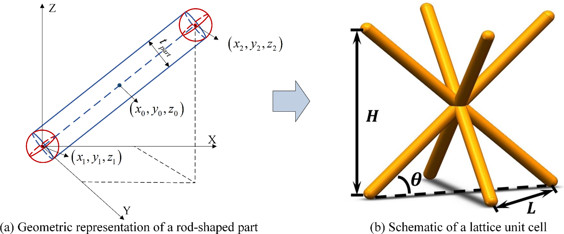
Figure 1: Schematic illustration of a lattice unit cell
And
where
It is observed from Fig. 1b that the lattice unit cell can be viewed as a combination of four rod-shaped parts. Thus, its TDF of a lattice unit cell can be expressed by
where
3.3 Lattice Property Estimation
Benefitting from the explicit geometry description based on a level set function, its effective density of a lattice unit cell can be calculated directly in a numerical integration way [25,37], as follows:
where
With the help of the numerical homogenization method as an effective means of estimating the effective mechanical properties of periodic materials, its effective elasticity tensors of a lattice unit cell can be calculated as follows [24,38,39]:
where i, j, k and l are equal to 1, 2, …, d, and d is the spatial dimension.
where
Based on the effective elasticity tensors of a lattice unit cell, its macroscopic stiffness matrix
where B is the strain-displacement matric. It is noted that the calculated macroscopic stiffness matrix
4 Thickness Optimization of Thin-Walled Structure
The workflow of designing thin-walled structure with lattice infill is shown in Fig. 2. In the structural requirement analysis phase, the design constraints and design objective are determined in accordance with the satellite requirements. In the infill lattice design phase, the structural geometry of the infill lattice is represented by the TDF in accordance with its design parameters. And the equivalent stiffness of infill lattice is calculated through the numerical homogenization method. In the thin-wall thickness optimization phase, the thickness of thin-wall is optimized for the minimum mass with the constraint of sufficient stiffness and fundamental frequency. In the geometry reconstruction phase, the apparent thin-wall is built, and the joint structures for screws are built as solids to improve the local mechanical strength. And the lattice infill is filled in the internal enclosed space of the thin-wall. Finally, the 3D model is outputted to be fabricated through AM.

Figure 2: Workflow of designing thin-walled structure with lattice infill
The connection relationship among the main supporting component, fuel tanks, and other part of satellite is shown in Fig. 3. The main supporting component is firmly connected to the other part of satellite by 16 screws, that is, a cylindrical shell. The diameter of main supporting component is 1255 mm. The weights of both fuel tanks supported by the main supporting component are 71.5 kg. They are fixed to the main supporting component by 16 screws.

Figure 3: Schematic of connection relationship among main supporting component, fuel tanks, and other part of satellite
In the thickness optimization model of thin-wall, the design constraints mainly include the dimension constraints and mechanical properties constrains. The dimension constraint is that the height of the fuel tank supporting component is less than 151 mm, which is limited by the spatial layout of various equipment inside the satellite. What’s more, the fuel tank supporting component is designed with six parts, as shown in Fig. 4. This is mainly because the SLM equipment with the limited fabrication dimension of 600 mm3 × 600 mm3 × 600 mm3 is used in this work.

Figure 4: Finite element model of the fuel tank supporting component
The mechanical properties constraint is that the fundamental frequency of the fuel tank supporting component is larger than 80 Hz, and the maximum stress is less than 100 MPa. The design objective is to minimize the mass of the fuel tank supporting component. The macroscopic shape of the thin-walled structure is a spherical crown with the height of 151 mm. A widely used body-centered cubic cell with dimensions of 5 mm3 × 5 mm3 × 5 mm3, and struts diameter of 0.5 mm is employed as the lattice infill. The finite element model of the thin-walled structure with lattice infill to be optimized is built, as shown in Fig. 4. The thin-wall is simulated with shell elements, and the lattice infill is simulated with homogenized solid elements. The boundary condition is the zero displacement constraint of the 16 screws at the edge of the fuel tank supporting component. Each fuel tank is simplified as a mass element with mass of 71.5 kg and inertia moment of 14.1 kg⋅m2 in three orthogonal directions. The mass element is connected to the fuel tank supporting component via the multipoint constraint element at the 16 screw positions. And thus, the optimization model of thin-walled structure can be formulated as follows:
where
The optimized results show that the variable thickness varies from 0.5 to 1.8 mm, and the mass of the fuel tank supporting component is 12.83 kg. The fundamental frequency is 86.1 Hz, and the maximum stress is 80 MPa, as shown in Figs. 5b and 5c. To sufficiently assess the effectiveness of the proposed design method, the comparison is conducted between the thin-walled structure with lattice infill and its traditional frame-type one. As shown in Figs. 6a and 6b, the mass of the frame-type structure is 15.4 kg. The fundamental frequency is 52.9 Hz, and the maximum stress is 70 MPa. It can be viewed that although the maximum stress of thin-walled structure with lattice infill is larger than that of the frame-type structure, its mass is reduced by 16.7%, and its fundamental frequency is increased nearly over half. The mentioned-above discussions and analysis demonstrate the effectiveness of the proposed method and the ultimate performance of designed thin-walled structure with lattice infill.

Figure 5: Mechanical analysis of thin-walled lattice structure for the fuel tank supporting component

Figure 6: Mechanical analysis of traditional frame-type structure for the fuel tank supporting component
The apparent thin-wall is built with Pro/E software in accordance with the optimized results. The joint structures for screws are built as solids to improve the local mechanical strength. The lattice infill is filled in the internal enclosed space of the thin-wall. The resulting model to be fabricated using AM technique is built by the merging the geometric models obtained in the former two processes as shown in Fig. 7.

Figure 7: Geometric modeling of fuel tank supporting component
5 Fabrication of Fuel Tank Supporting Component
AlSi10Mg alloy powder, with an average particle diameter of 30 μm, is used to fabricate the bracket via the SLM equipment (BLT-S600) supplied by BLT Company. The main process parameters are as follows: laser power 200–300 W, scan speed 1000 mm/s–2000 mm/s, hatch spacing 0.15 mm–0.20 mm, and layer thickness 30 μm. The SLM-fabricated structure is annealed at 200°C–300°C for 3 h to release residual stress and enhance ductility properties. Before welding, the region to be welded is machined to remove the oxide and impurities, in order to improve the welding quality and dimensional precision. Cold metal transfer welding is used in this work because of its superiority in welding aluminum alloy thin-wall structures with excessively small heat input. The width of welding lines ranges from 5 mm to 8 mm, and no sag in welding lines or other visible defects are found by X inspection. After the welding, heat treatment is conducted to release the residual stress. Finally, the integrated structure is machined at the interfaces between the fuel tank supporting component and fuel tanks or cylindrical shell of the satellite to ensure the installation accuracy being superior to 0.1 mm. The SLM fabricated parts before and after welding is shown in Fig. 8.
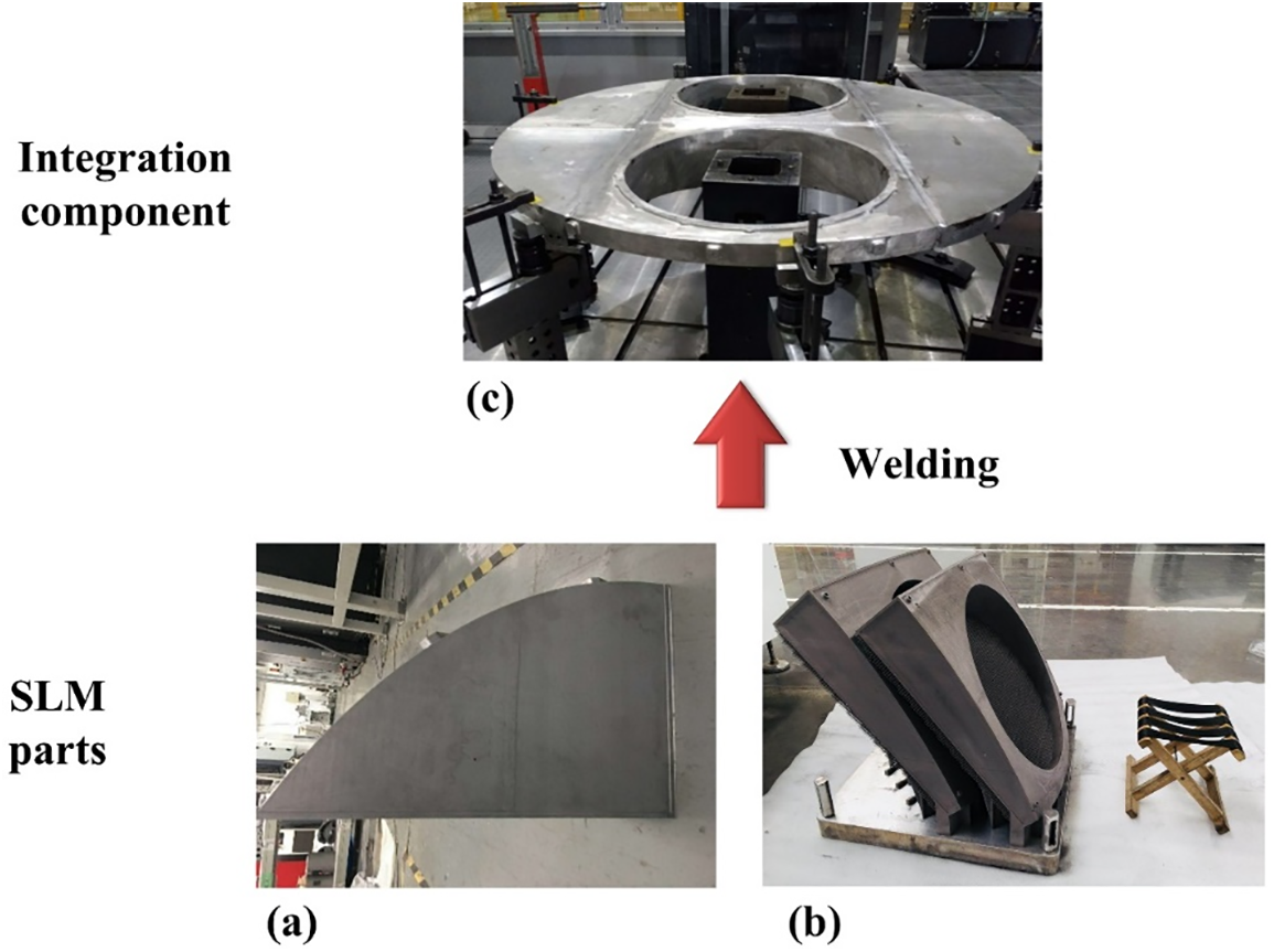
Figure 8: Photos of the SLM fabricated parts before and after welding
6 Quasi-Static Mechanical and Vibration Experiments
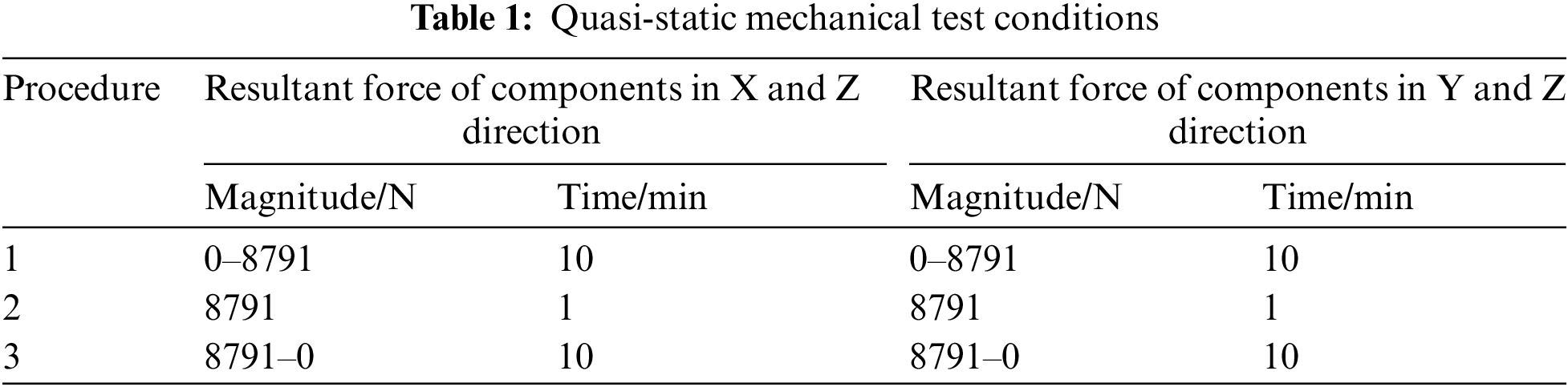
Quasi-static mechanical tests are conducted to examine the mechanical strength of the fuel tank supporting component. The schematic and photo of the test system are illustrated in Figs. 9a and 9b. The fuel tank supporting component is connected to a cylindrical shell, which is an imitation of the principal cylinder of the satellite and is fixed to the ground. Two circular steel disks with diameter of 507 mm are used as the imitation of two fuel tanks. Each circular disk is connected to the fuel tank supporting component by 16 screws. Two loading beams are connected to the circular disks with a hinge joint. Vertical (Z direction) and horizontal forces (X or Y direction) are simultaneously applied to each disk by adjusting the angle between the loading beam and disk. The resultant force applied to each beam is measured using a force sensor. The test procedure is shown in Table 1. The resultant force of components in X and Z directions is loaded from 0 to 8791 N in 10 min. Then, the peak force is held for 1 min. The force is unloaded from 8791 to 0 N in 10 min. The test procedure for the resultant force of components in Y and Z directions is the same as that in X and Z directions. The vertical displacement at the loading points and the internal edge of the fuel tank supporting component are measured with four displacement sensors, as shown in Fig. 9c. The strain at 34 points, especially the positions close to the welding lines and screws, are measured using strain rosettes. The positions of the strain rosettes are shown in Fig. 9d. The strain rosettes on the top surface and that on the lower surface of the fuel tank supporting component are 17.

Figure 9: Experimental setup for uniaxial compressive tests (a) and (b), and schematic of displacement and strain sensing positions (c) and (d)
Besides the quasi-static mechanical tests, vibration experiments are also implemented to verify the rationality of structure design and manufacturing process quality of the SLM and cold metal transfer welding. The fuel tank supporting component is assembled to the principle cylinder of satellite by screws. The entire satellite is exposed to the vibration loads in X (horizontal), Y (horizontal), and Z directions (vertical), respectively. The photo of the vibration test system is illustrated in Fig. 10a. The acceleration of fuel tank supporting component is measured with three acceleration sensors. The positions of three acceleration sensors are shown in Fig. 10b. The conditions of sinusoidal vibration experiments are listed in Table 2.

Figure 10: Photo of the installed fuel tank supporting component (a), and schematic of acceleration monitoring positions for vibration experiments (b)
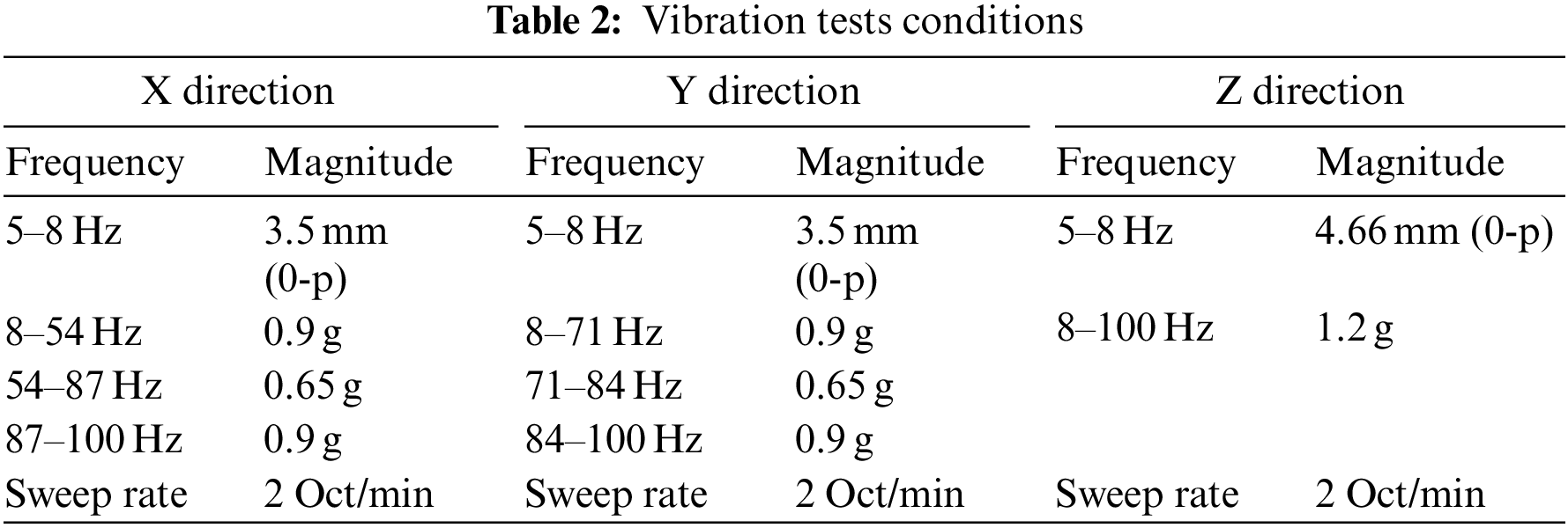
The frequency of the sinusoidal vibration is increased monotonically from 5 to 100 Hz. The maximum magnitudes of the loads are 0.9 g (from 8 to 100 Hz) in the X or Y direction and 1.2 g (from 8 to 100 Hz) in the Z direction. However, the magnitude is decreased to 0.65 g from 54 to 87 Hz in the X direction and from 71 to 84 Hz in the Y direction to avoid the strength failure of other equipment on the satellite caused by local structural resonance, which is larger than the vibration magnitude during real launching. The sweep rate of vibration is 2 Octave per minute, i.e., the frequency of the sinusoidal vibration increased by quadruple in every minute.
The vertical displacements at the monitoring positions are plotted in Fig. 11. It can be seen that the displacement increases as the loading force increases. The maximum displacement is 2.65 mm. The displacement decreases as the unloading force decreases. The residual displacement is 0 mm∼0.15 mm, which is small enough to be neglected for large structures with assembling stress. It should be noted that no “instant displacement/force drop” phenomenon occurs during the loading and unloading process, indicating that no fracture occurs in the fuel tank supporting component.

Figure 11: Displacement results of quasi-static mechanical tests
The strains measured at different positions of the fuel tank supporting component are plotted in Fig. 12. The strain increases when the loading force increases, and decreases when the unloading force decreases. It agrees well with the variation tendency of the displacement. The maximum strain is 390 με, and the residual strain is 0∼45 με. The maximum stress and residual stress can be estimated by the strain multiplied by the elastic modulus of the AlSi10Mg thin-walled structure, i.e., about 60 GPa. The maximum stress and residual stress are estimated to be 23.4 and 2.7 MPa, respectively. The stresses are far below the yield strength of AlSi10Mg, which is approximately 160 MPa. The strain measurement results of quasi-static mechanical tests verify the elastic deformation of the fuel tank supporting component. That is to say, the fuel tank supporting component has not been damaged during the quasi-static mechanical tests.

Figure 12: Strain results of quasi-static mechanical tests
The acceleration response monitored in the X, Y and Z direction are plotted in Fig. 13. It can be seen that the Z directional sinusoidal vibration loads stimulate the first order structural resonance of the fuel tank supporting component at the frequency of 80.8 Hz. The value is smaller than the calculated value 86.1 Hz. This finding is mainly because the real boundary condition of the fuel tank supporting component is unideal clamped boundary due to the flexibility of the cylindrical shell, fuel tanks and other parts of satellite. The maximum acceleration responses in the X, Y and Z direction are 3.5, 3.8, and 5.4 g, respectively.
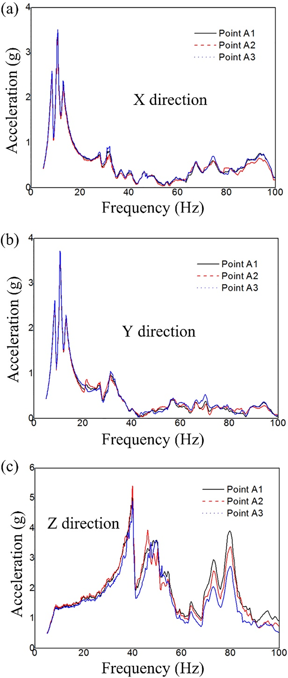
Figure 13: Acceleration response monitored in X direction (a), Y direction (b) and Z direction (c)
Low-magnitude vibration excitation is applied to the satellite before and after vibration experiments to examine whether the resonant frequencies are altered for the structural degradation or not [1,40], considering that the resonant frequencies can be changed as a result of structural failure or damage [41]. The low-magnitude vibration excitation is 0.1 g, which increases from 5 to 100 Hz monotonously at a sweep rate of 4 Oct/min. The acceleration responses monitored by the sensors are plotted in Fig. 14. The acceleration response stimulated by low-magnitude vibration excitation before and after vibration experiments almost overlap with each other, in spite of small discrepancy that usually resulted from the variation in assembly stress of the assembly containing structural parts and connections. Therefore, it is justifiable to conclude that the fuel tank supporting component fabricated through SLM has not been damaged during the high-magnitude vibration tests, and there is no structural fracture or plastic deformation found. That is to say, the fuel tank supporting component made of thin-wall and lattice infill manufactured by the SLM technique could sustain the vibration during the rocket launching.
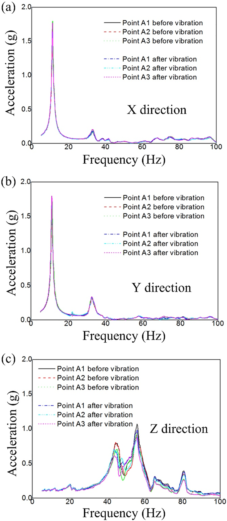
Figure 14: Acceleration response comparison before and after vibration experiments in X direction (a), Y direction (b), and Z direction (c) in response to low-magnitude vibration excitation
To summarize, the largest known thin-walled structure with lattice infill with the diameter of 1.255 m is designed and fabricated through SLM technique and cold metal transfer welding. The structure is used as the fuel tank supporting component of the satellite. Quasi-static mechanical tests and vibration tests verify the strength of the fuel tank supporting component. The recovery deformation in quasi-static mechanical tests and unaltered resonance frequencies in vibration tests confirm that no structural failure occurs during the mechanical experiments. The design and verification approach presented in this work can benefit the application of large scale thin-walled structures with lattice infill used as fuel tank supporting components in the aerospace field and others.
Funding Statement: The authors are grateful for the support by National Key Research and Development Program of China (2021YFF0500300, 2020YFB1708300) and the National Natural Science Foundation of China (52205280, 12172041).
Author Contributions: The authors confirm contribution to the paper as follows: study conception and design: Xiaoyu Zhang, Hao Zhou, Liang Gao; data collection: Huizhong Zeng, Shaohui Zhang, Liping Liu, Hao Zhou; analysis and interpretation of results: Xiaoyu Zhang, Yan Zhang. Mi Xiao, Hongyou Chai, Liang Gao; draft manuscript preparation: Xiaoyu Zhang, Hao Zhou, Yan Zhang. Mi Xiao. All authors reviewed the results and approved the final version of the manuscript.
Availability of Data and Materials: The data that support the findings of this study are available from the first and corresponding authors upon reasonable request.
Conflicts of Interest: The authors declare that they have no conflicts of interest to report regarding the present study.
References
1. Zhang, X., Zhou, H., Shi, W., Zeng, F., Zeng, H. et al. (2018). Vibration tests of 3D printed satellite structure made of lattice sandwich panels. AIAA Journal, 56(10), 4213–4217. https://doi.org/10.2514/1.J057241 [Google Scholar] [CrossRef]
2. Zhou, H., Zhang, X. Y., Zeng, H. Z., Yang, H. N., Lei, H. S. et al. (2019). Lightweight structure of a phase-change thermal controller based on lattice cells manufactured by SLM. Chinese Journal of Aeronautics, 32(7), 1727–1732. https://doi.org/10.1016/j.cja.2018.08.017 [Google Scholar] [CrossRef]
3. Wang, C., Zhu, J. H., Wu, M. Q., Hou, J., Zhou, H. et al. (2021). Multi-scale design and optimization for solid-lattice hybrid structures and their application to aerospace vehicle components. Chinese Journal of Aeronautics, 34(5), 386–398. https://doi.org/10.1016/j.cja.2020.08.015 [Google Scholar] [CrossRef]
4. Niu, B., Wadbro, E. (2021). Multiscale design of coated structures with periodic uniform infill for vibration suppression. Computers & Structures, 255, 106622. https://doi.org/10.1016/j.compstruc.2021.106622 [Google Scholar] [CrossRef]
5. Bai, L., Gong, C., Chen, X., Zheng, J., Yang, J. et al. (2022). Heterogeneous compressive responses of additively manufactured Ti-6Al-4V lattice structures by varying geometric parameters of cells. International Journal of Mechanical Sciences, 214, 106922. https://doi.org/10.1016/j.ijmecsci.2021.106922 [Google Scholar] [CrossRef]
6. Wei, K., Yang, Q., Yang, X., Tao, Y., Xie, H. et al. (2020). Mechanical analysis and modeling of metallic lattice sandwich additively fabricated by selective laser melting. Thin-Walled Structures, 146, 106189. https://doi.org/10.1016/j.tws.2019.106189 [Google Scholar] [CrossRef]
7. Dallago, M., Raghavendra, S., Luchin, V., Zappini, G., Pasini, D. et al. (2021). The role of node fillet, unit-cell size and strut orientation on the fatigue strength of Ti-6Al-4V lattice materials additively manufactured via laser powder bed fusion. International Journal of Fatigue, 142, 105946. https://doi.org/10.1016/j.ijfatigue.2020.105946 [Google Scholar] [CrossRef]
8. Li, P., Ma, Y. E., Sun, W., Qian, X., Zhang, W. et al. (2022). Mechanical behaviors and failure modes of additive manufactured Ti6Al4V lattice structures under compressive load. Thin-Walled Structures, 180, 109778. https://doi.org/10.1016/j.tws.2022.109778 [Google Scholar] [CrossRef]
9. Sing, S., Yeong, W., Wiria, F., Tay, B. (2016). Characterization of titanium lattice structures fabricated by selective laser melting using an adapted compressive test method. Experimental Mechanics, 56(5), 735–748. https://doi.org/10.1007/s11340-015-0117-y [Google Scholar] [CrossRef]
10. Liu, L., Kamm, P., Garcia-Moreno, F., Banhart, J., Pasini, D. (2017). Elastic and failure response of imperfect three-dimensional metallic lattices: The role of geometric defects induced by selective laser melting. Journal of the Mechanics and Physics of Solids, 107, 160–184. https://doi.org/10.1016/j.jmps.2017.07.003 [Google Scholar] [CrossRef]
11. Lei, H., Li, C., Meng, J., Zhou, H., Liu, Y. et al. (2019). Evaluation of compressive properties of SLM-fabricated multi-layer lattice structures by experimental test and μ-CT-based finite element analysis. Materials & Design, 169, 107685. https://doi.org/10.1016/j.matdes.2019.107685 [Google Scholar] [CrossRef]
12. Li, C., Lei, H., Liu, Y., Zhang, X., Xiong, J. et al. (2018). Crushing behavior of multi-layer metal lattice panel fabricated by selective laser melting. International Journal of Mechanical Sciences, 145, 389–399. https://doi.org/10.1016/j.ijmecsci.2018.07.029 [Google Scholar] [CrossRef]
13. Rashed, M. G., Ashraf, M., Mines, R. A. W., Hazell, P. J. (2016). Metallic microlattice materials: A current state of the art on manufacturing, mechanical properties and applications. Materials & Design, 95, 518–533. https://doi.org/10.1016/j.matdes.2016.01.146 [Google Scholar] [CrossRef]
14. Wang, P., Yang, F., Lu, G., Bian, Y., Zhang, S. et al. (2022). Anisotropic compression behaviors of bio-inspired modified body-centered cubic lattices validated by additive manufacturing. Composites Part B: Engineering, 234, 109724. https://doi.org/10.1016/j.compositesb.2022.109724 [Google Scholar] [CrossRef]
15. Bai, L., Gong, C., Chen, X., Zheng, J., Xin, L. et al. (2021). Quasi-static compressive responses and fatigue behaviour of Ti-6Al-4V graded lattice structures fabricated by laser powder bed fusion. Materials & Design, 210, 110110. https://doi.org/10.1016/j.matdes.2021.110110 [Google Scholar] [CrossRef]
16. Bici, M., Brischetto, S., Campana, F., Ferro, C. G., Seclì, C. et al. (2018). Development of a multifunctional panel for aerospace use through SLM additive manufacturing. Procedia Cirp, 67, 215–220. https://doi.org/10.1016/j.procir.2017.12.202 [Google Scholar] [CrossRef]
17. Wu, J., Clausen, A., Sigmund, O. (2017). Minimum compliance topology optimization of shell–infill composites for additive manufacturing. Computer Methods in Applied Mechanics and Engineering, 326, 358–375. https://doi.org/10.1016/j.cma.2017.08.018 [Google Scholar] [CrossRef]
18. Clausen, A., Aage, N., Sigmund, O. (2016). Exploiting additive manufacturing infill in topology optimization for improved buckling load. Engineering, 2(2), 250–257. https://doi.org/10.1016/J.ENG.2016.02.006 [Google Scholar] [CrossRef]
19. Wadbro, E., Niu, B. (2019). Multiscale design for additive manufactured structures with solid coating and periodic infill pattern. Computer Methods in Applied Mechanics and Engineering, 357, 112605. https://doi.org/10.1016/j.cma.2019.112605 [Google Scholar] [CrossRef]
20. Zhou, M., Lu, Y., Liu, Y., Lin, Z. (2022). Concurrent topology optimization of shells with self-supporting infills for additive manufacturing. Computer Methods in Applied Mechanics and Engineering, 390, 114430. https://doi.org/10.1016/j.cma.2021.114430 [Google Scholar] [CrossRef]
21. Liu, C., Du, Z., Zhu, Y., Zhang, W., Zhang, X. et al. (2020). Optimal design of shell-graded-infill structures by a hybrid MMC-MMV approach. Computer Methods in Applied Mechanics and Engineering, 369, 113187. https://doi.org/10.1016/j.cma.2020.113187 [Google Scholar] [CrossRef]
22. Zhang, Y., Xiao, M., Zhang, X., Gao, L. (2020). Topological design of sandwich structures with graded cellular cores by multiscale optimization. Computer Methods in Applied Mechanics and Engineering, 361, 112749. https://doi.org/10.1016/j.cma.2019.112749 [Google Scholar] [CrossRef]
23. Zhang, Y., Zhang, L., Ding, Z., Gao, L., Xiao, M. et al. (2022). A multiscale topological design method of geometrically asymmetric porous sandwich structures for minimizing dynamic compliance. Materials & Design, 214, 110404. https://doi.org/10.1016/j.matdes.2022.110404 [Google Scholar] [CrossRef]
24. Xiao, M., Liu, X., Zhang, Y., Gao, L., Gao, J. et al. (2021). Design of graded lattice sandwich structures by multiscale topology optimization. Computer Methods in Applied Mechanics and Engineering, 384, 113949. https://doi.org/10.1016/j.cma.2021.113949 [Google Scholar] [CrossRef]
25. Liu, X., Gao, L., Xiao, M., Zhang, Y. (2022). Kriging-assisted design of functionally graded cellular structures with smoothly-varying lattice unit cells. Computer Methods in Applied Mechanics and Engineering, 390, 114466. https://doi.org/10.1016/j.cma.2021.114466 [Google Scholar] [CrossRef]
26. Li, S., Yuan, S., Zhu, J., Zhang, W., Zhang, H. et al. (2021). Multidisciplinary topology optimization incorporating process-structure-property-performance relationship of additive manufacturing. Structural and Multidisciplinary Optimization, 63(5), 2141–2157. https://doi.org/10.1007/s00158-021-02856-9 [Google Scholar] [CrossRef]
27. Bi, M., Tran, P., Xie, Y. M. (2020). Topology optimization of 3D continuum structures under geometric self-supporting constraint. Additive Manufacturing, 36, 101422. https://doi.org/10.1016/j.addma.2020.101422 [Google Scholar] [CrossRef]
28. van de Ven, E., Maas, R., Ayas, C., Langelaar, M., van Keulen, F. (2020). Overhang control based on front propagation in 3D topology optimization for additive manufacturing. Computer Methods in Applied Mechanics and Engineering, 369, 113169. https://doi.org/10.1016/j.cma.2020.113169 [Google Scholar] [CrossRef]
29. Xiong, Y., Yao, S., Zhao, Z. L., Xie, Y. M. (2020). A new approach to eliminating enclosed voids in topology optimization for additive manufacturing. Additive Manufacturing, 32, 101006. https://doi.org/10.1016/j.addma.2019.101006 [Google Scholar] [CrossRef]
30. Wang, C., Qian, X. (2020). Simultaneous optimization of build orientation and topology for additive manufacturing. Additive Manufacturing, 34, 101246. https://doi.org/10.1016/j.addma.2020.101246 [Google Scholar] [CrossRef]
31. Wang, D., Yang, Y., Yi, Z., Su, X. (2013). Research on the fabricating quality optimization of the overhanging surface in SLM process. The International Journal of Advanced Manufacturing Technology, 65(9), 1471–1484. https://doi.org/10.1007/s00170-012-4271-4 [Google Scholar] [CrossRef]
32. Dallago, M., Winiarski, B., Zanini, F., Carmignato, S., Benedetti, M. (2019). On the effect of geometrical imperfections and defects on the fatigue strength of cellular lattice structures additively manufactured via selective laser melting. International Journal of Fatigue, 124, 348–360. https://doi.org/10.1016/j.ijfatigue.2019.03.019 [Google Scholar] [CrossRef]
33. Chen, Z., Wu, X., Tomus, D., Davies, C. H. (2018). Surface roughness of selective laser melted Ti-6Al-4V alloy components. Additive Manufacturing, 21, 91–103. https://doi.org/10.1016/j.addma.2018.02.009 [Google Scholar] [CrossRef]
34. Zhou, H., Cao, X., Li, C., Zhang, X., Fan, H. et al. (2021). Design of self-supporting lattices for additive manufacturing. Journal of the Mechanics and Physics of Solids, 148, 104298. https://doi.org/10.1016/j.jmps.2021.104298 [Google Scholar] [CrossRef]
35. Chu, S., Gao, L., Xiao, M., Li, H. (2019). Design of sandwich panels with truss cores using explicit topology optimization. Composite Structures, 210, 892–905. https://doi.org/10.1016/j.compstruct.2018.12.010 [Google Scholar] [CrossRef]
36. Zhang, W., Yuan, J., Zhang, J., Guo, X. (2016). A new topology optimization approach based on moving morphable components (MMC) and the ersatz material model. Structural and Multidisciplinary Optimization, 53(6), 1243–1260. https://doi.org/10.1007/s00158-015-1372-3 [Google Scholar] [CrossRef]
37. Zhang, Y., Xiao, M., Gao, L., Gao, J., Li, H. (2020). Multiscale topology optimization for minimizing frequency responses of cellular composites with connectable graded microstructures. Mechanical Systems and Signal Processing, 135, 106369. https://doi.org/10.1016/j.ymssp.2019.106369 [Google Scholar] [CrossRef]
38. Andreassen, E., Andreasen, C. S. (2014). How to determine composite material properties using numerical homogenization. Computational Materials Science, 83, 488–495. https://doi.org/10.1016/j.commatsci.2013.09.006 [Google Scholar] [CrossRef]
39. Zhang, L., Ding, Z., Sha, W., Zhang, Y., Xiao, M. et al. (2023). Level set-based topological design of multiphase micro-architectured materials using alternating active-phase method. Materials & Design, 225, 111448. https://doi.org/10.1016/j.matdes.2022.111448 [Google Scholar] [CrossRef]
40. Tang, M., Pistorius, P. C. (2017). Anisotropic mechanical behavior of AlSi10Mg parts produced by selective laser melting. JOM, 69(3), 516–522. https://doi.org/10.1007/s11837-016-2230-5 [Google Scholar] [CrossRef]
41. Pearce, M., Lund, J., Lundin, M., Lundquist, J. (2002). Random vibration tests of the anticoincidence system of the PAMELA satellite experiment. Nuclear Instruments and Methods in Physics Research Section A: Accelerators, Spectrometers, Detectors and Associated Equipment, 488(3), 536–542. https://doi.org/10.1016/S0168-9002(02)00562-4 [Google Scholar] [CrossRef]
Cite This Article
 Copyright © 2024 The Author(s). Published by Tech Science Press.
This work is licensed under a Creative Commons Attribution 4.0 International License , which permits unrestricted use, distribution, and reproduction in any medium, provided the original work is properly cited.
 Downloads
 Citation Tools