
 Submit a Paper
 Propose a Special lssue
 Open Access
ARTICLE

An 8-Node Plane Hybrid Element for Structural Mechanics Problems Based on the Hellinger-Reissner Variational Principle
1 School of Rail Transportation, Soochow University, Suzhou, 215131, China
2 Soochow College, Soochow University, Suzhou, 215006, China
* Corresponding Author: Linquan Yao. Email:
Computer Modeling in Engineering & Sciences 2024, 138(2), 1277-1299. https://doi.org/10.32604/cmes.2023.030508
Received 10 April 2023; Accepted 18 July 2023; Issue published 17 November 2023
 View Full Text
 Download PDF
Abstract
The finite element method (FEM) plays a valuable role in computer modeling and is beneficial to the mechanical design of various structural parts. However, the elements produced by conventional FEM are easily inaccurate and unstable when applied. Therefore, developing new elements within the framework of the generalized variational principle is of great significance. In this paper, an 8-node plane hybrid finite element with 15 parameters (PH-Q8-) is developed for structural mechanics problems based on the Hellinger-Reissner variational principle. According to the design principle of Pian, 15 unknown parameters are adopted in the selection of stress modes to avoid the zero energy modes. Meanwhile, the stress functions within each element satisfy both the equilibrium and the compatibility relations of plane stress problems. Subsequently, numerical examples are presented to illustrate the effectiveness and robustness of the proposed finite element. Numerical results show that various common locking behaviors of plane elements can be overcome. The PH-Q8- element has excellent performance in all benchmark problems, especially for structures with varying cross sections. Furthermore, in bending problems, the reasonable mesh shape of the new element for curved edge structures is analyzed in detail, which can be a useful means to improve numerical accuracy.Keywords
The FEM is a computational tool for engineering design analysis; it fundamentally revolutionized the way we perform scientific modeling and engineering design, including automobiles, aircraft, marine structures, bridges, highways, and high-rise buildings [1–9]. Traditional isoparametric elements are often limited by various numerical problems, such as limited computational accuracy and sensitivity to mesh distortion. For instance, the accuracy of the 4-node isoparametric element (Q4) may be obviously limited for bending problems due to shear locking. To improve the performance of these finite element methods, new finite element formulations need to be derived and applied to mechanical problems.
Over the past few decades, numerous techniques have been proposed for developing new finite element models based on various generalized variational principles. Pian et al. [10,11] pioneered the hybrid element method using an assumed stress field in the element and an assumed displacement field along element boundaries. Cen et al. [12] improved on Pian’s hybrid element approach to develop 8- and 12-node plane elements. The new elements perform well and can work in highly distorted meshes. Sze et al. [13–18] developed a hybrid stress-assumed natural strain 8-node solid shell element unaffected by shear, membrane, trapezoidal, thickness, and dilatational locking. This element is computationally more efficient than conventional hybrid elements because it adopts orthogonal assumed stress modes and enforces admissible sparsity in the flexibility matrix. Moreover, this element was generalized for smart structure modeling by the piezoelectric effect. Jog et al. [19] presented 4-node and 9-node elements for the development of hybrid axisymmetric elements based on the Hellinger-Reissner principle within the context of linear elasticity. Several examples were presented to show the excellent performance of both elements in various situations. Ma et al. [20] proposed a 24 degree of freedom (DOF) quadrilateral hybrid stress element for couple stress theory. Reduced integration and a stress smoothing technique were introduced to improve the accuracy of this element. Numerical results showed that this element could pass the enhanced patch test for a convergence condition. Bussamra et al. [21] proposed hexahedral hybrid-mixed finite elements for free vibration analysis of three-dimensional solids. These elements were free of shear and volumetric locking and had low sensitivity to mesh distortion. Agrawal et al. [22] used hybrid finite element methodology to develop an efficient and robust method based on the Hellinger-Reissner variational principle towards developing an efficient and robust finite element-based contact strategy. The proposed contact formulation can effectively model the contact interaction of thin as well as thick geometries as well as contact between bodies made of almost incompressible materials. Xie et al. [23] developed an atomistic-informed crystal plasticity finite element method to capture the evolution of geometrically compatible dislocation patterns as well as crystal plasticity in body-centered cubic crystals at micron or submicron scales. Liu et al. [24] established a novel three-dimensional progressive damage model based on the generalized mixed finite element method to investigate the strength and failure behaviors of notched composite laminate plates. The stress distribution of notched isotropic plates under tension was studied, and the results verified the good accuracy of the method. Ping and co-workers [25–27] used a specific finite element eigen-analysis method to predict the singular stress field around the tips of cracks, notches, and inclusions within the framework of the Hellinger-Reissner variational principle. Based on this, they [28] proposed an adaptive FEM to examine the issues with fracture propagation in anisotropic materials, bi-materials, and isotropic materials. Ramtekkar et al. [29] developed a refined 6-node two-dimensional mixed finite element to analyze a laminated composite using the minimum potential energy principle. The results obtained through the model showed excellent agreement with the elastic solution. Additionally, smoothed FEMs can also increase numerical solution accuracy, and the core idea behind this method is to combine the strain smoothing methodology of meshfree methods into the standard finite element method [30–32]. According to [33,34], smoothed FEMs can be viewed as specific assumed strain or stress methods for generalized variational principles.
The quadrilateral isoparametric elements contain Lagrangian elements and Serendipity elements. The Lagrangian elements are more computationally expensive than the Serendipity elements since they contain internal nodes. Thus, the Serendipity elements are preferred in practical applications, especially the 8-node isoparametric element (Q8). As the biquadratic interpolation functions are adopted for the Q8 element, it has better accuracy compared with the Q4 element and the Wilson-incompatible element. However, the Q8 element is extremely sensitive to mesh distortion [35]. The design of 8-node plane elements that can both improve the accuracy and overcome the above shortcomings has been a research hotspot. Dhananjaya et al. [36] presented a new 8-node Serendipity quadrilateral plate bending element based on Mindlin-Reissner theory using the integrated force method. This new element performs excellently in both thin and moderately thick plate bending situations. Dang et al. [37] presented a hybrid element model derived from a two-field variational functional; the plausible equilibrated stress field within each element was derived using Airy’s stress functions. The results indicated that this hybrid element was less sensitive to geometric distortion and was more accurate for stress than standard finite elements. Wang et al. [38,39] derived a new 8-node assumed stress quasi-conforming plane element based on the Bernstein basis function and Airy’s stress function. This element was not affected by mesh distortions and could adjust to the mesh shape, which deformed into a triangle or concave quadrangle with curved elements. However, derivations of 8-node plane hybrid elements for solving structural mechanics problems based on the Hellinger-Reissner variational principle have rarely been reported in previous literature. In this paper, the formulation of the PH-Q8-
The outline of this paper is as follows. In Section 2, a new 8-node plane hybrid finite element is proposed based on the Hellinger-Reissner variational principle, and subsequently, the finite element formulation is derived. Numerical examples with results and discussions are presented in Section 3. Finally, a brief conclusion is presented in Section 4.
2 Finite Element Equations of the 8-Node Hybrid Element
2.1 The Hellinger-Reissner Variational Principle
Consider a linear elastic body with volume
The equilibrium equation
The strain–displacement relationship
The constitutive relationship
The Neumann condition
The Dirichlet condition
where
Then, Eqs. (1)–(5) can be expressed in terms of two independent fields,
The domain of the elastic body is divided into
where
The stationary condition of Eq. (8) is:
2.2 Interpolation Functions of Variable Fields in Elements
A standard 8-node element in the natural coordinate system is shown in Fig. 1a, and a curved edge element after the isoparametric transformation in the Cartesian coordinate system is shown in Fig. 1b. For isoparametric elements, the interpolation functions of the coordinates and displacements are the same, i.e.,

Figure 1: Plane quadrilateral 8-node isoparametric element
where
where
where (
The strain matrix can be obtained from Eq. (11):
where the geometric matrix
and
The relationship between the natural coordinates (
where the Jacobi matrix J is given by:
In the hybrid element analysis, the performance of the elements constructed on the basis of different assumed stress fields differs. Therefore, the key to deriving a hybrid element with superior performance lies in the selection of stress functions. Because the plane stresses are required to satisfy the continuity in each element, the stress functions are derived based on Eq. (1) by using the Airy stress function. To overcome the zero energy modes and ensure the efficiency of the calculation, it is necessary to determine the number of stress parameters and express them in
where
For a generic element, the stress function in the Cartesian coordinate system can be converted from Eq. (19) by the transformation matrix,
where
Notably, the form of Eq. (20) obtained by using the Airy stress function is usually not unique. Eq. (20) possesses the advantages of good accuracy, good stability and strong universality in numerical examples. For special problems, such as fracture problems, more complex assumed stress functions can be used to construct the optimal element.
2.3 Derivation of the Finite Element Formulation
Substituting the displacement matrix
where
where
From the stationary condition of the energy functional,
Eq. (25) imposes a strong geometric constraint on the displacement vector
Substituting Eqs. (27) into (26), we obtain:
where
By using Eqs. (23), (27) and (28), the energy functional of the elastic body can be expressed as:
where
After imposing displacement boundary conditions, the stiffness matrix
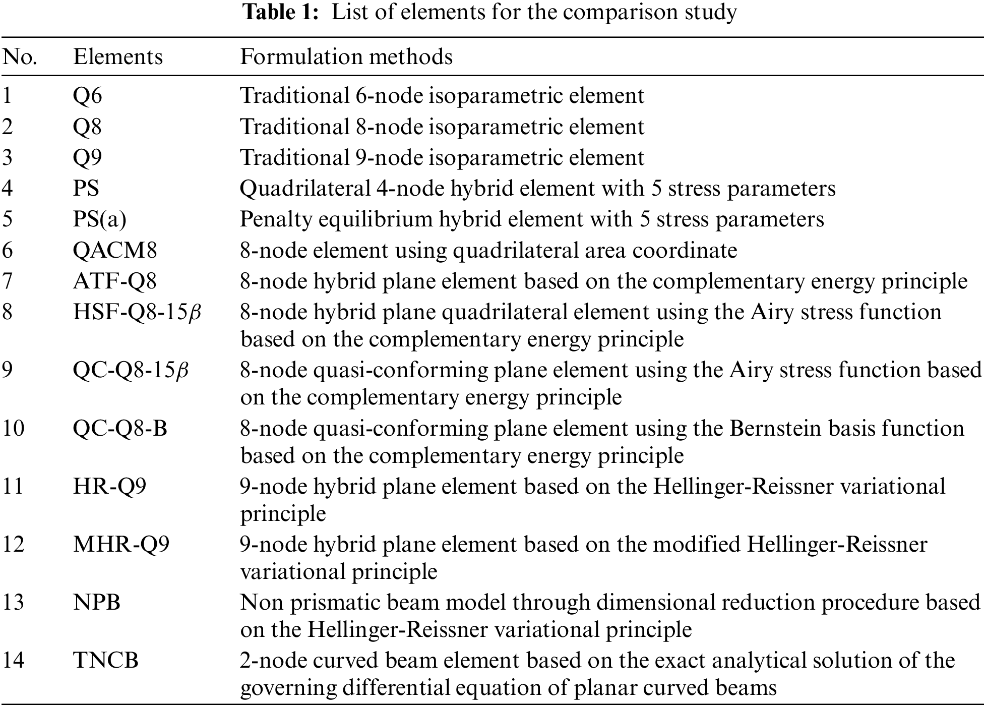
In this section, seven problems are presented to evaluate the performance of the PH-Q8-
where
A rectangular panel (0.24 × 0.001 × 0.12) is divided into five irregular elements, as shown in Fig. 2. The material properties of the panel are Young's modulus
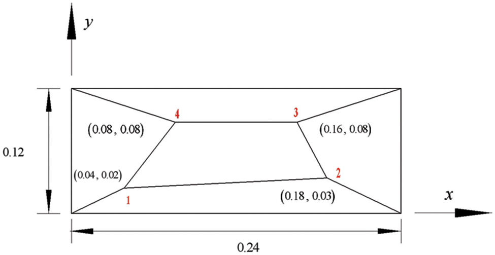
Figure 2: The patch test of membrane elements
3.2 Cantilever Beam with Five Irregular Elements
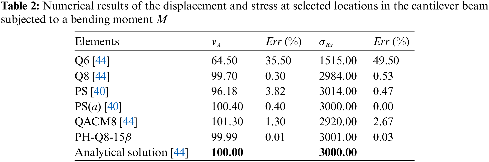
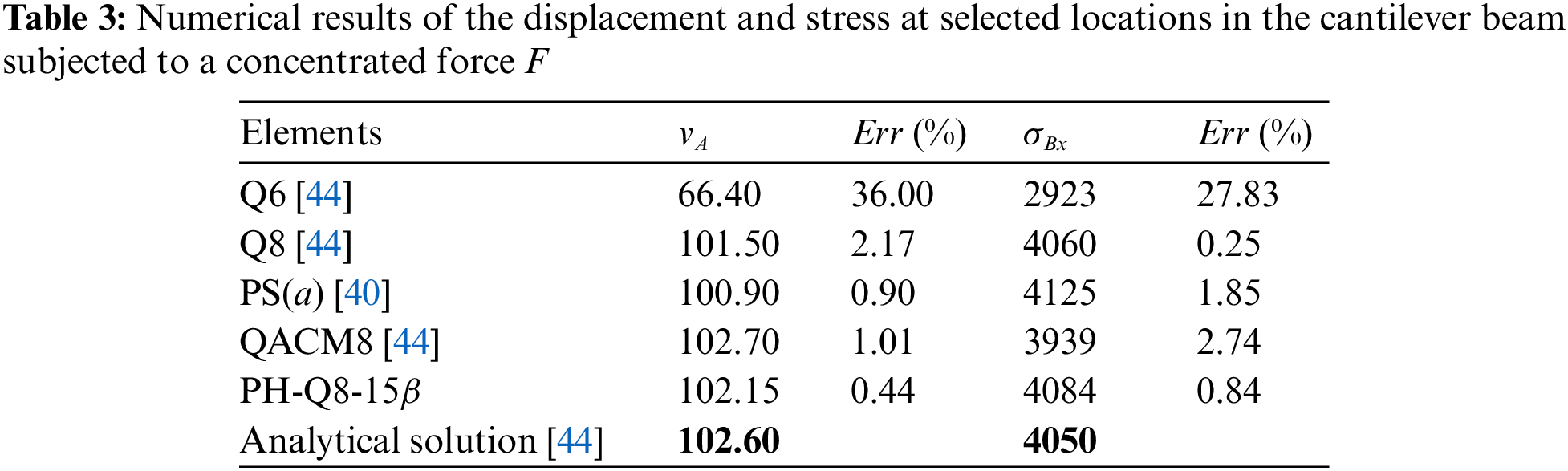
A cantilever beam with five irregular elements is subjected to the concentrated load
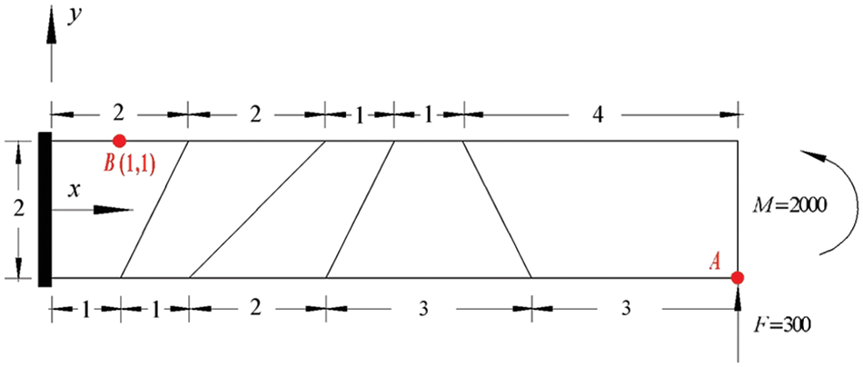
Figure 3: A cantilever beam with five irregular elements
3.3 Sensitivity Test for Mesh Distortion and Convergence Analysis
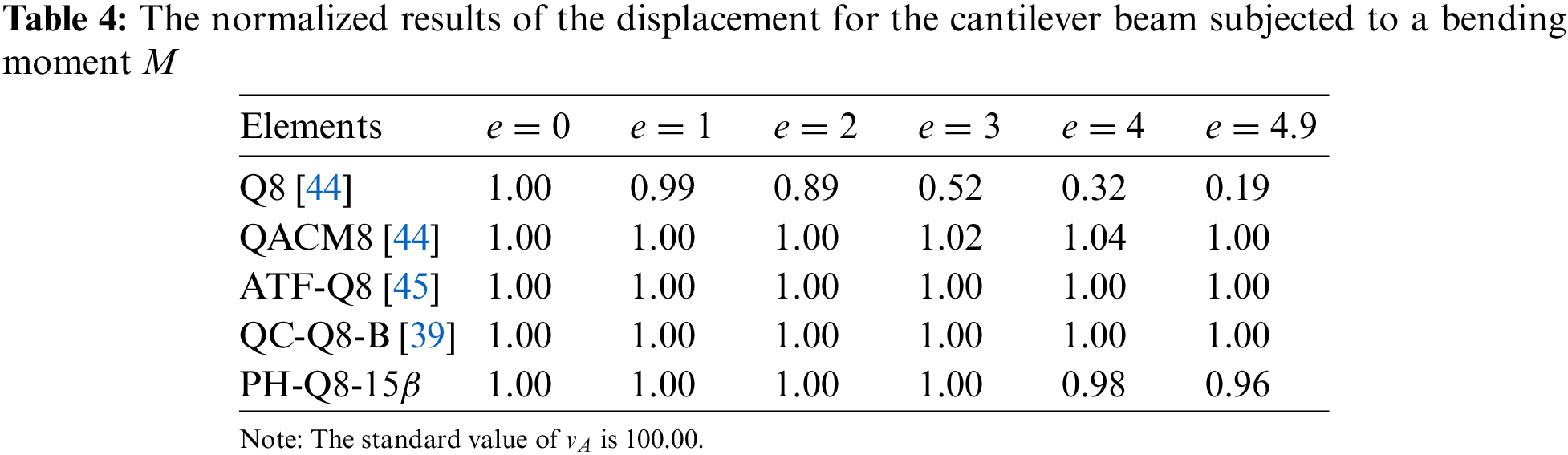
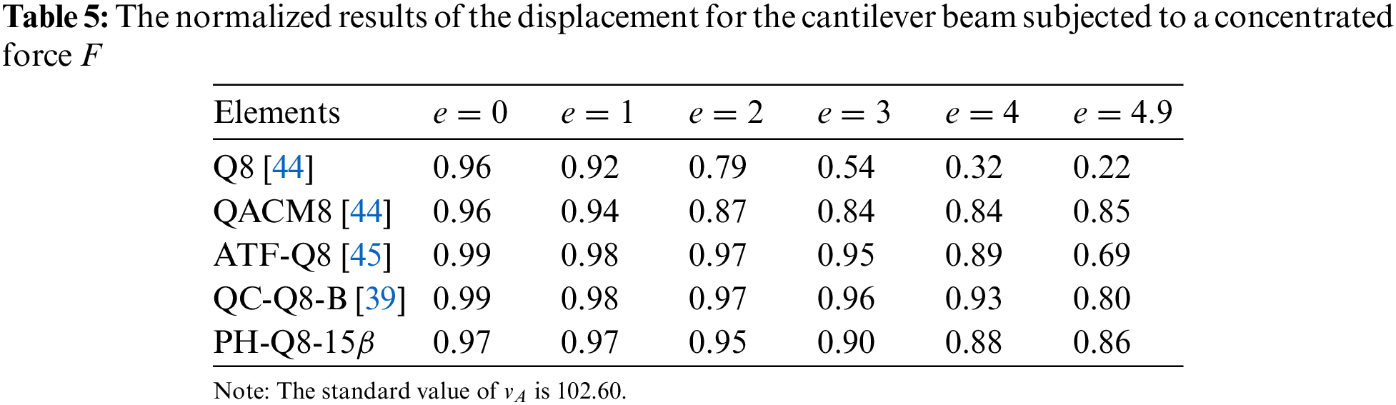
A cantilever beam is subjected to two different loads, as shown in Fig. 4. The beam is discretized using two elements, and
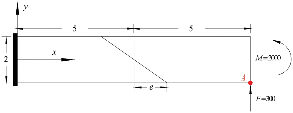
Figure 4: A cantilever beam divided by two elements with distortion parameter
We define the displacement norm error as follows in order to further analyze the convergence of the PH-Q8-
where v and
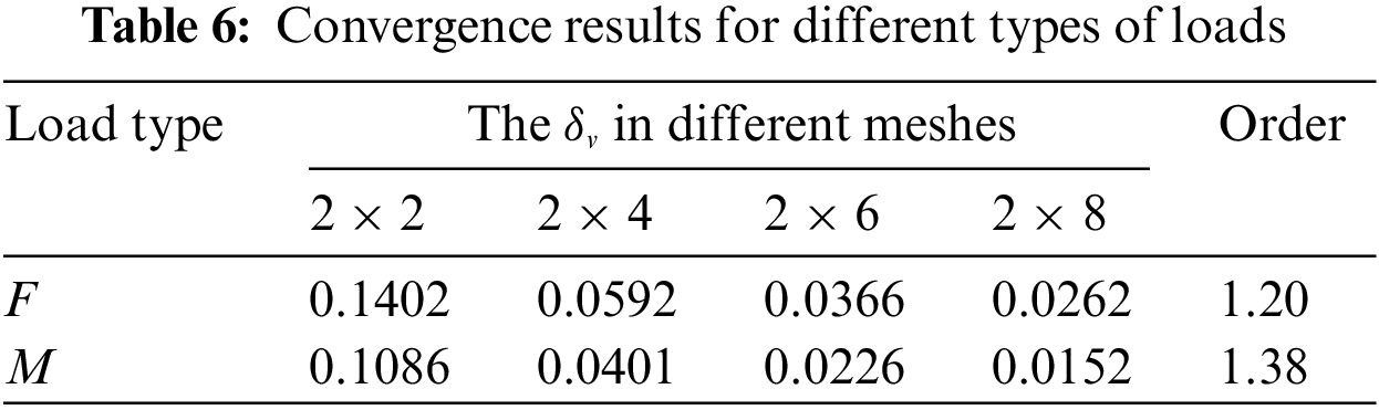
The displacement norm error is calculated using a typical mesh type, as illustrated in Fig. 5. Numerical results are shown in Table 6. We can observe that the results for vertical displacement attain first order convergence.

Figure 5: Typical mesh type models for convergence test
3.4 Bending for a Curving Beam with the Uniform Cross Section
A curved cantilever beam subjected to a concentrated force
where
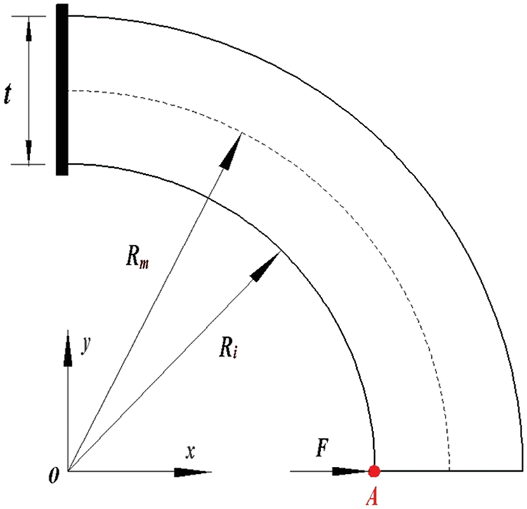
Figure 6: Curved cantilever beam
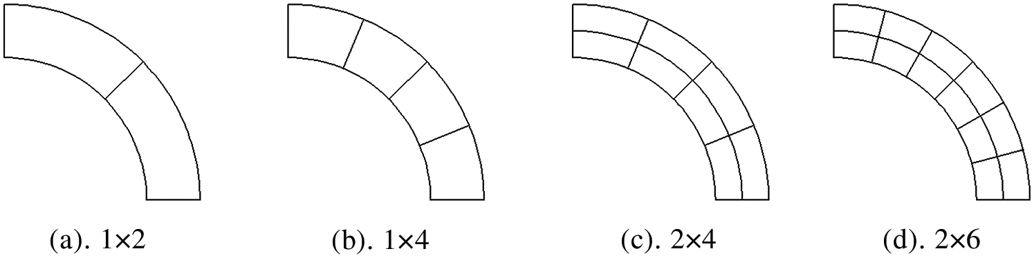
Figure 7: Typical mesh type models for the curved cantilever beam
Numerical results of the radial displacement
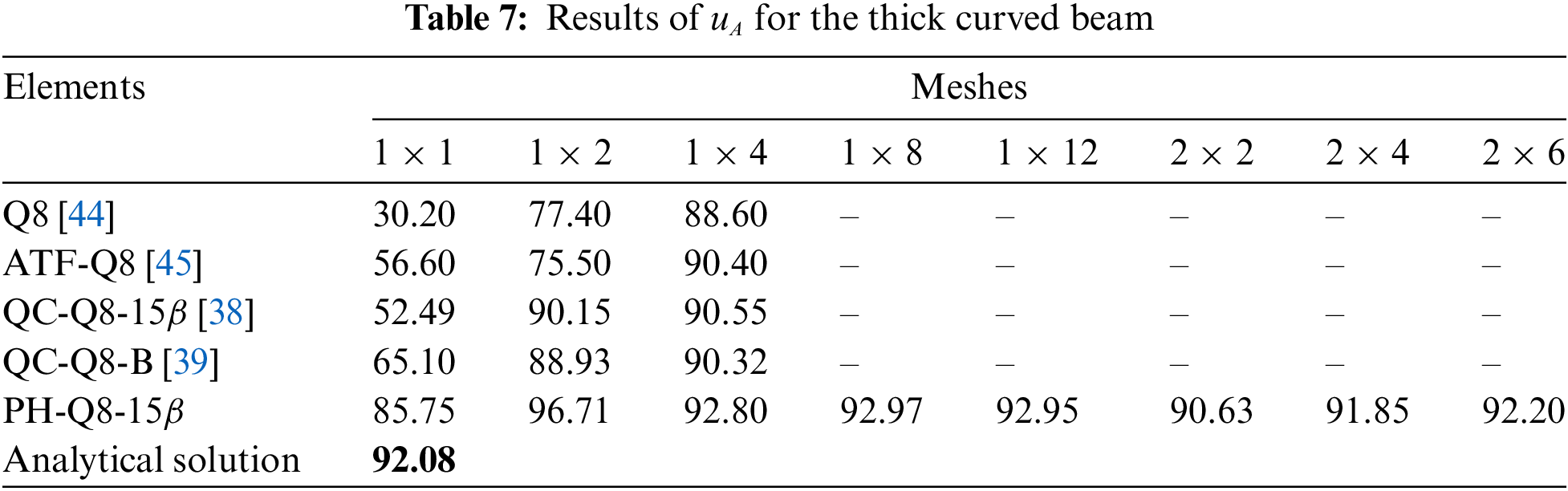
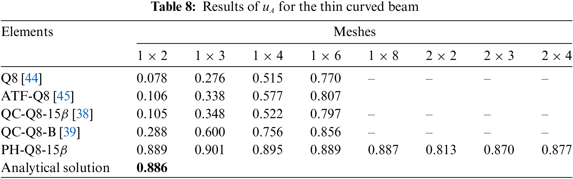
The effects of the mesh type on the numerical accuracy for the PH-Q8-
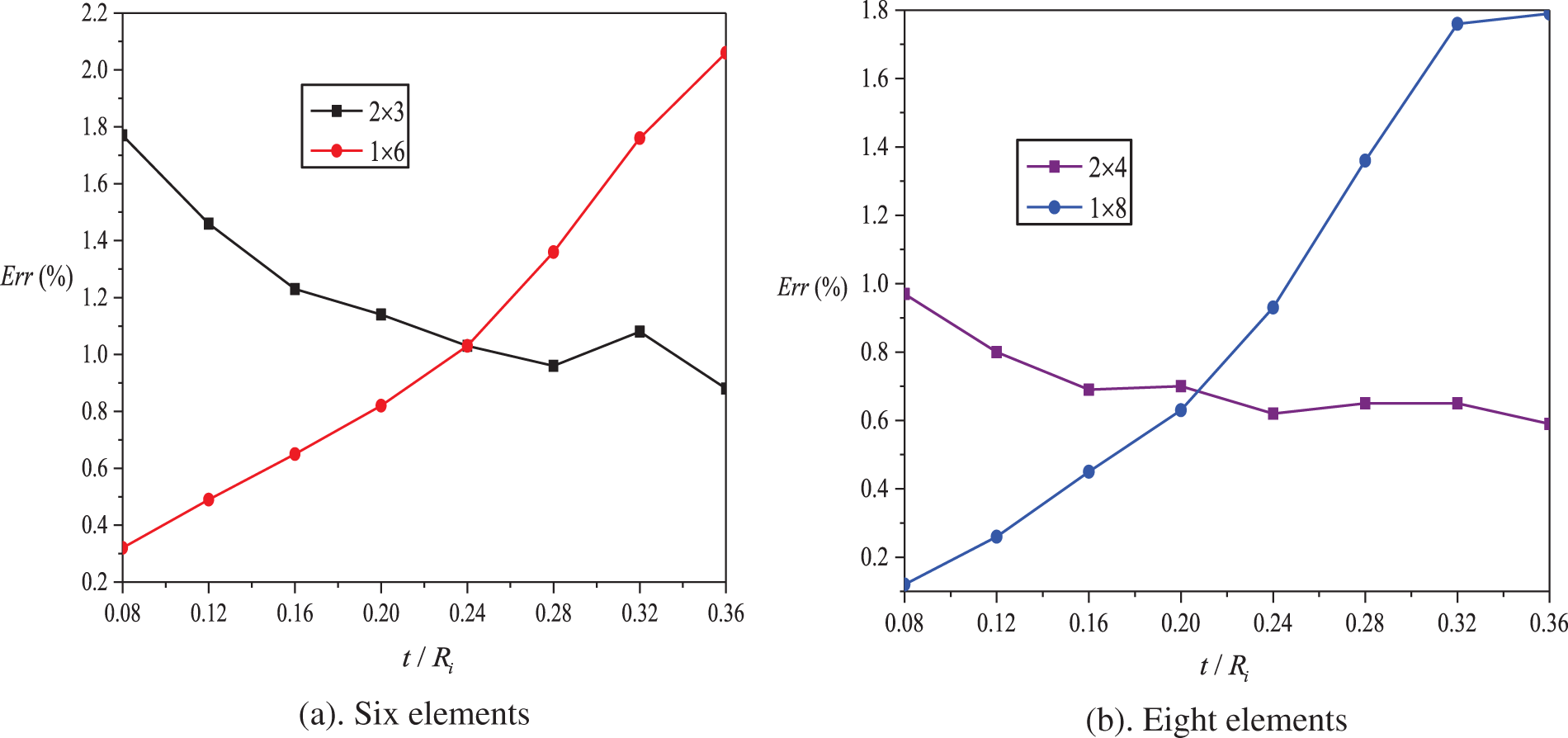
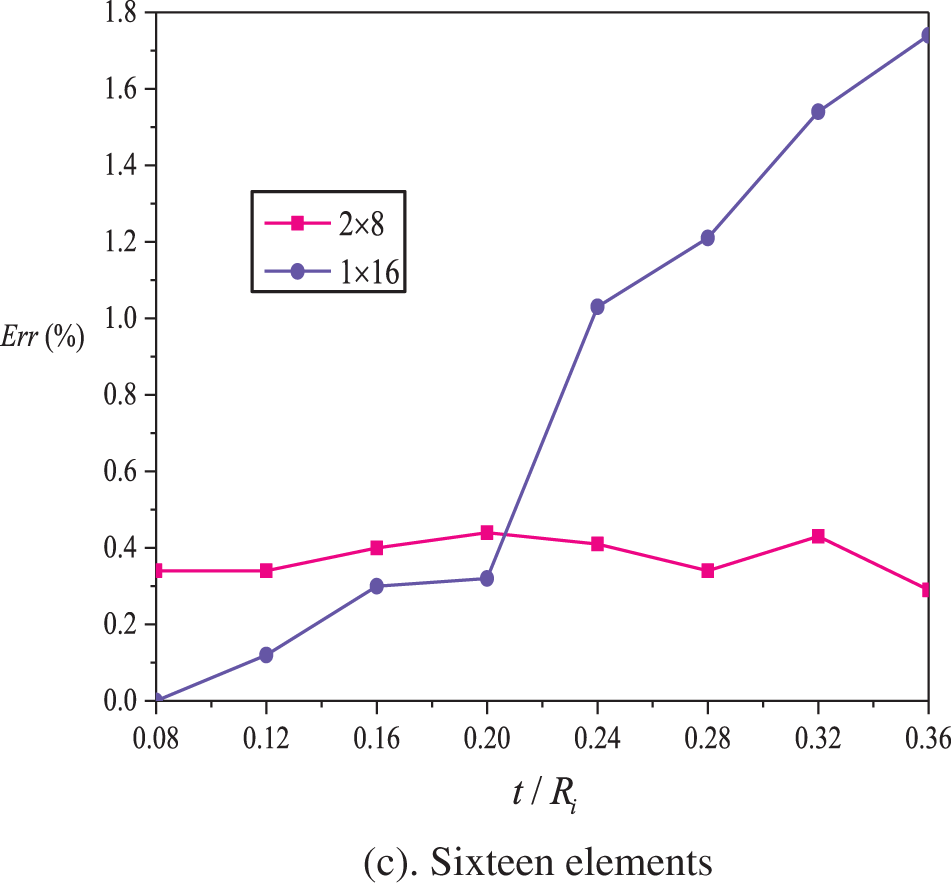
Figure 8: Influence of mesh type and
This test, proposed by Macneal and Harder, is a well-known benchmark for testing sensitivity to mesh distortion [47]. Three different mesh shapes in Fig. 9 are adopted: rectangular, parallelogram and trapezoidal. Two load types are considered: the bending moment and the concentrated force. The geometry and material properties are as follows: length
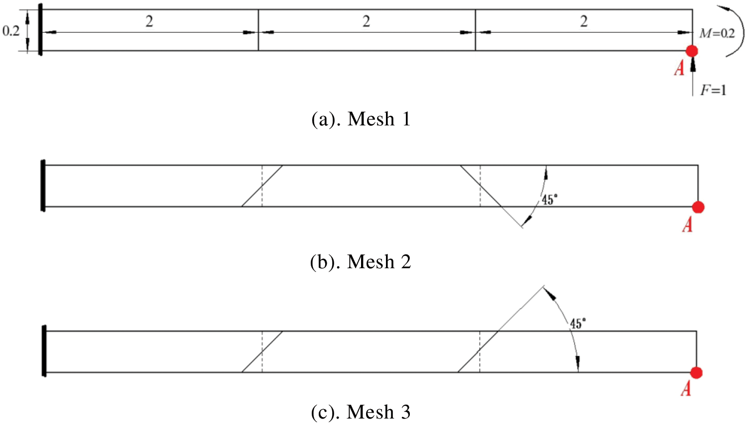
Figure 9: MacNeal thin beams
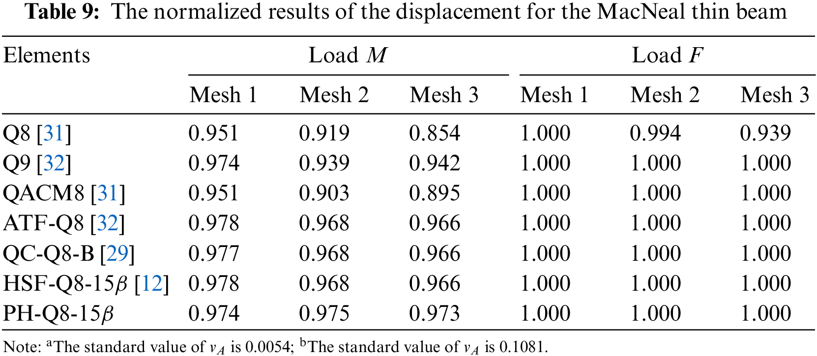
Additionally, shear locking can be alleviated by using bubble functions for a general plane stress problem; the functions are typically high-order displacement polynomials that are zero on the element boundaries [48,49]. This strategy, however, may improve the accuracy of elements with linear displacement modes (e.g., the Q4 element) but is not appropriate for the Q8 element. Because the Q8 element has a fully displacement mode that simulates the constant bending strain state.
Membrane locking can be examined by the analysis of a ring, and many arch elements exhibit membrane locking in the analysis of deep arches even though they may give good results in the analysis of shallow arches [50]. A ring is subjected to two pinching concentrated loads
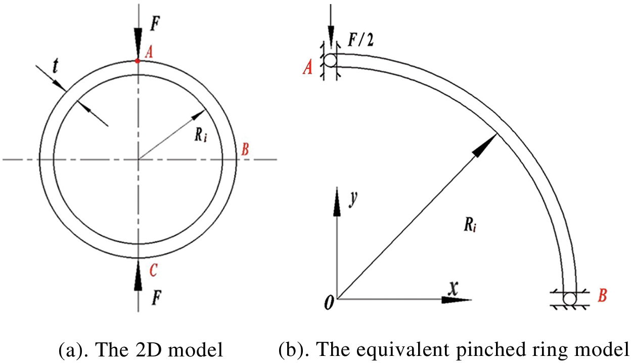
Figure 10: Pinched ring
According to the conclusion in Subsection 3.4, the single-layer mesh is adopted for the quarter of the thin pinched ring. Numerical results of the radial deflection
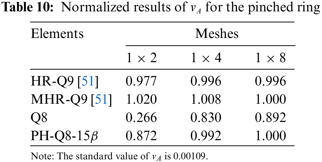
Through the two examples in this subsection, it is evident that the proposed element has greatly improved the Q8 element and overcomes the common locking behaviors in plane stress problems. Meanwhile, when compared to other 8-node elements in the literature, better numerical accuracy was demonstrated.
3.6 Axisymmetric Annular Plate with Uniformly Distributed Internal Pressure
An axisymmetric annular plate is subjected to a uniformly distributed internal pressure
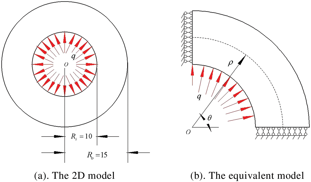
Figure 11: Axisymmetric annular plate with uniformly distributed internal pressure
The stress solutions of
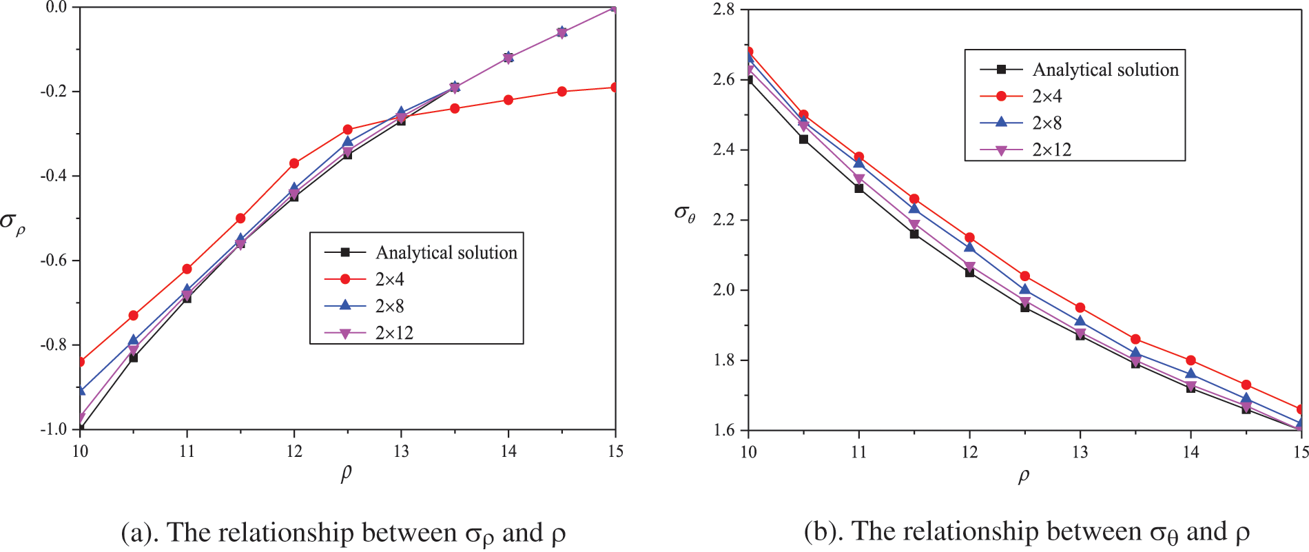
Figure 12: The variation in the radial stress
3.7 Straight/Curved Beams with Varying Cross Sections
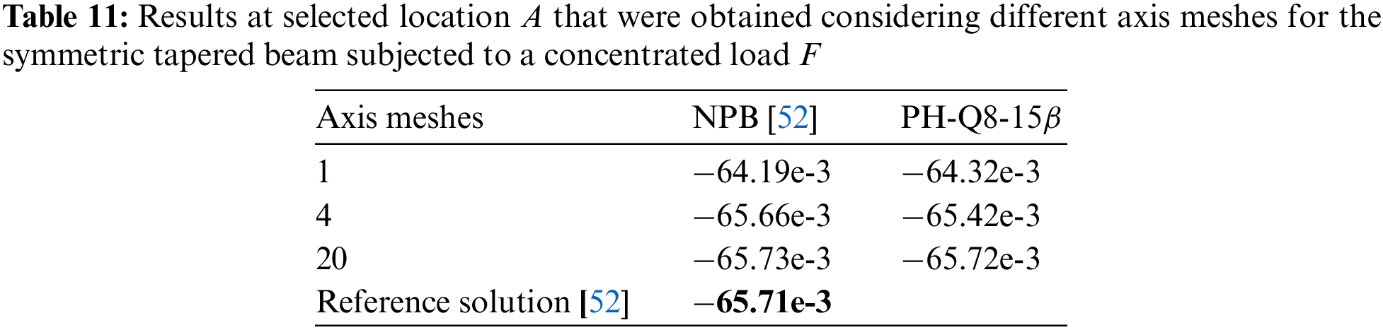
A symmetric tapered beam is subjected to a concentrated load
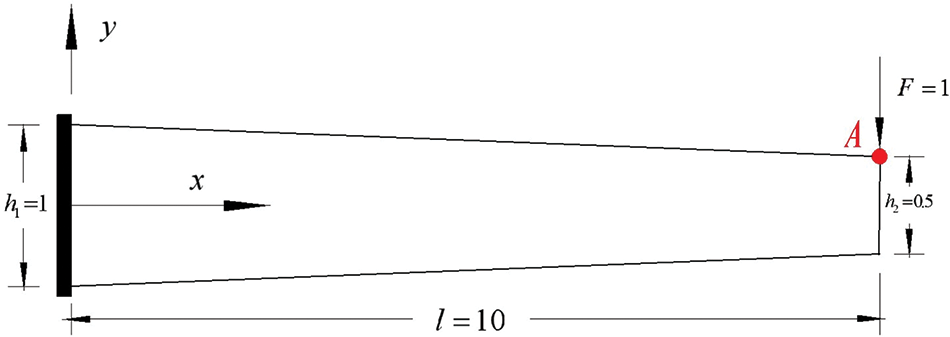
Figure 13: A symmetric tapered beam
A cantilever curving beam with a varying cross section is subjected to a concentrated load
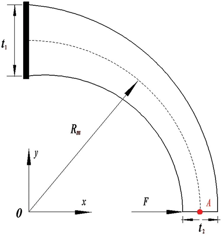
Figure 14: A curved beam with varying cross section
The single-layer mesh is adopted, as shown in Fig. 7. The results obtained by the 80 TNCB elements in [53] are taken as reference solutions and listed in Table 12. Fig. 15 shows the effects of the number of elements on the relative error between the numerical results obtained by the PH-Q8-
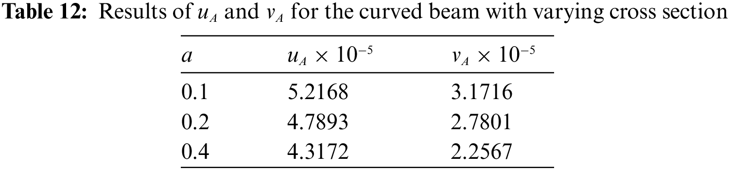
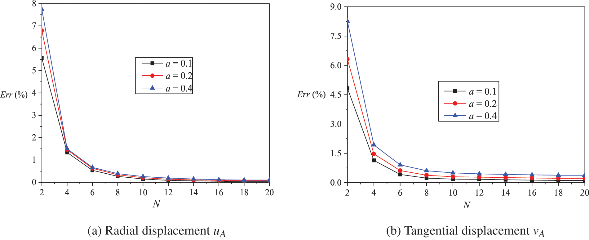
Figure 15: The variation in the relative error relative to the number of elements N for the curved beam with varying cross section
Because of the shortcomings of the Q8 element, a new PH-Q8-
In the future, we will extend the new PH-Q8-
Acknowledgement: The authors would like to thank the editor and the reviewers for their constructive comments which improve the quality of the paper.
Funding Statement: This paper was supported by the National Natural Science Foundation of China (No. 11572210).
Author Contributions: The authors confirm contribution to the paper as follows: methodology and writing original draft: Haonan Li; investigation and software: Wei Wang; investigation and data curation: Quan Shen; validation and project administration: Linquan Yao. All authors reviewed the results and approved the final version of the manuscript.
Availability of Data and Materials: Data and materials will be made available by reasonable requests.
Conflicts of Interest: The authors declare that they have no conflicts of interest to report regarding the present study.
References
1. Liu, W. K., Li, S., Park, H. S. (2022). Eighty years of the finite element method: Birth, evolution, and future. Archives of Computational Methods in Engineering, 29(6), 4431–4453. https://doi.org/10.1007/s11831-022-09740-9 [Google Scholar] [CrossRef]
2. Truong, V. H., Liu, J., Meng, X. H., Jiang, C., Nguyen, T. T. (2018). Uncertainty analysis on vehicle-bridge system with correlative interval variables based on multidimensional parallelepiped model. International Journal of Computational Methods, 15(5), 1850030. https://doi.org/10.1142/S0219876218500305 [Google Scholar] [CrossRef]
3. Li, D., Tian, J., Shi, S., Wang, S., Deng, J. et al. (2023). Lightweight design of commercial vehicle cab based on fatigue durability. Computer Modeling in Engineering & Sciences, 136(1), 421–445. https://doi.org/10.32604/cmes.2023.024133 [Google Scholar] [PubMed] [CrossRef]
4. Wang, Y., Li, Z., Li, Z., Wang, Y. (2023). Finite element simulation of radial tire building and shaping processes using an elasto-viscoplastic model. Computer Modeling in Engineering & Sciences, 135(2), 1187–1208. https://doi.org/10.32604/cmes.2022.022596 [Google Scholar] [PubMed] [CrossRef]
5. Mehraban, A., Tufo, H., Sture, S., Regueiro, R. (2021). Matrix-free higher-order finite element method for parallel simulation of compressible and nearly-incompressible linear elasticity on unstructured meshes. Computer Modeling in Engineering & Sciences, 129(3), 1283–1303. https://doi.org/10.32604/cmes.2021.017476 [Google Scholar] [PubMed] [CrossRef]
6. Liu, H., Zhang, Q., Ma, J. (2021). Thermo-mechanical dynamics of two-dimensional FG microbeam subjected to a moving harmonic load. Acta Astronautica, 178, 681–692. https://doi.org/10.1016/j.actaastro.2020.09.045 [Google Scholar] [CrossRef]
7. van Vinh, P., Huy, L. Q. (2022). Finite element analysis of functionally graded sandwich plates with porosity via a new hyperbolic shear deformation theory. Defence Technology, 18(3), 490–508. https://doi.org/10.1016/j.dt.2021.03.006 [Google Scholar] [CrossRef]
8. Bach, D. P., Brancherie, D., Cauvin, L. (2022). An embedded-FEM approach accounting for the size effect in nanocomposites. Computational Mechanics, 70(4), 745–762. https://doi.org/10.1007/s00466-022-02194-7 [Google Scholar] [CrossRef]
9. Choi, M. J., Klinkel, S., Sauer, R. A. (2022). An isogeometric finite element formulation for frictionless contact of Cosserat rods with unconstrained directors. Computational Mechanics, 70(6), 71107. https://doi.org/10.1007/s00466-022-02223-5 [Google Scholar] [CrossRef]
10. Pian, T. H. H. (1964). Derivation of element stiffness matrices by assumed stress distributions. AIAA Journal, 2(7), 1333–1336. https://doi.org/10.2514/3.2546 [Google Scholar] [CrossRef]
11. Pian, T. H. H., Sumihara, K. (1984). Rational approach for assumed stress finite elements. International Journal for Numerical Methods in Engineering, 20(9), 1685–1695. https://doi.org/10.1002/nme.1620200911 [Google Scholar] [CrossRef]
12. Cen, S., Fu, X. R., Zhou, M. J. (2011). 8- and 12-node plane hybrid stress-function elements immune to severely distorted mesh containing elements with concave shapes. Computer Methods in Applied Mechanics & Engineering, 200(29–32), 2321–2336. https://doi.org/10.1016/j.cma.2011.04.014 [Google Scholar] [CrossRef]
13. Sze, K. Y., Yao, L. Q. (2000). A hybrid stress ANS solid-shell element and its generalization for smart structure modelling. Part I—Solid-shell element formulation. International Journal for Numerical Methods in Engineering, 48, 545–564. [Google Scholar]
14. Sze, K. Y., Yao, L. Q., Yi, S. (2000). A hybrid stress ANS solid-shell element and its generalization for smart structure modelling. Part II—Smart structure modelling. International Journal for Numerical Methods in Engineering, 48, 565–582. [Google Scholar]
15. Sze, K. Y., Yao, L. Q. (2000). Modelling smart structures with segmented piezoelectric sensors and actuators. Journal of Sound and Vibration, 235(3), 495–520. https://doi.org/10.1006/jsvi.2000.2944 [Google Scholar] [CrossRef]
16. Sze, K. Y., Lo, S. H., Yao, L. Q. (2002). Hybrid-stress solid elements for shell structures based upon a modified variational functional. International Journal for Numerical Methods in Engineering, 53, 2617–2642. https://doi.org/10.1002/nme.402 [Google Scholar] [CrossRef]
17. Sze, K. Y., Yao, L. Q., Pian, T. H. H. (2002). An eighteen-node hybrid-stress solid-shell element for homogenous and laminated structures. Finite Elements in Analysis and Design, 38(4), 353–374. https://doi.org/10.1016/S0168-874X(01)00089-0 [Google Scholar] [CrossRef]
18. Yao, L. Q., Lu, L. (2003). Hybrid-stabilized solid-shell model of laminated composite piezoelectric structures under non-linear distribution of electric potential through thickness. International Journal for Numerical Methods in Engineering, 58, 1499–1522. https://doi.org/10.1002/nme.823 [Google Scholar] [CrossRef]
19. Jog, C. S., Annabattula, R. (2006). The development of hybrid axisymmetric elements based on the Hellinger-Reissner variational principle. International Journal for Numerical Methods in Engineering, 65, 2279–2291. https://doi.org/10.1002/nme.1552 [Google Scholar] [CrossRef]
20. Ma, X., Chen, W. (2013). 24-DOF quadrilateral hybrid stress element for couple stress theory. Computational Mechanics, 53(1), 159–172. https://doi.org/10.1007/s00466-013-0899-7 [Google Scholar] [CrossRef]
21. Bussamra, F. L. S., Lucena Neto, E., Cardoso, F. R. (2018). Three-dimensional hybrid-mixed stress elements for free vibration analysis. Finite Elements in Analysis and Design, 140(5–6), 50–58. https://doi.org/10.1016/j.finel.2017.11.004 [Google Scholar] [CrossRef]
22. Agrawal, M., Nandy, A., Jog, C. S. (2019). A hybrid finite element formulation for large-deformation contact mechanics. Computer Methods in Applied Mechanics & Engineering, 356(6), 407–434. https://doi.org/10.1016/j.cma.2019.07.017 [Google Scholar] [CrossRef]
23. Xie, Y., Li, S. (2021). Finite temperature atomistic-informed crystal plasticity finite element modeling of single crystal tantalum (α-Ta) at micron scale. International Journal for Numerical Methods in Engineering, 122, 4660–4697. https://doi.org/10.1002/nme.6741 [Google Scholar] [CrossRef]
24. Liu, W., Yu, F., He, Z., Qing, G. (2020). A high-precision progressive damage model based on generalized mixed finite element method. Archive of Applied Mechanics, 90(3), 559–571. https://doi.org/10.1007/s00419-019-01625-x [Google Scholar] [CrossRef]
25. Chen, M. C., Ping, X. C., Xie, H. M., Liu, Z. W. (2008). Numerical and experimental analyses of singular electro-elastic fields around a V-shaped notch tip in piezoelectric materials. Engineering Fracture Mechanics, 75(18), 5029–5041. https://doi.org/10.1016/j.engfracmech.2008.05.011 [Google Scholar] [CrossRef]
26. Ping, X. C., Chen, M. C., Zheng, B. B., Xu, B. (2013). An effective numerical analysis of singular stress fields in dissimilar material wedges under thermo-mechanical loads. Engineering Fracture Mechanics, 106(17), 22–37. https://doi.org/10.1016/j.engfracmech.2013.03.028 [Google Scholar] [CrossRef]
27. Ping, X. C., Wang, C. G., Cheng, L. P., Chen, M. C., Xu, J. Q. (2018). A super crack front element for three-dimensional fracture mechanics analysis. Engineering Fracture Mechanics, 196(4), 1–27. https://doi.org/10.1016/j.engfracmech.2018.04.016 [Google Scholar] [CrossRef]
28. Wang, C. M., Ping, X. C., Wang, X. X. (2023). An adaptive finite element method for crack propagation based on a multifunctional super singular element. International Journal of Mechanical Sciences, 247(12), 108191. https://doi.org/10.1016/j.ijmecsci.2023.108191 [Google Scholar] [CrossRef]
29. Ramtekkar, G. D., Patel, K. S., Desai, Y. M. (2023). A six-node refined mixed finite element model for the analysis of fiber reinforced polymer composite beams. Composite Structures, 304(2), 116418. https://doi.org/10.1016/j.compstruct.2022.116418 [Google Scholar] [CrossRef]
30. Liu, G. R., Nguyen-Thoi, T. (2010). Smoothed finite element methods. New York: CRC Press. [Google Scholar]
31. Nguyen, T. K., Nguyen, V. H., Thanh, C. D., Vo, T. P., Nguyen-Xuan, H. (2016). Static and vibration analysis of isotropic and functionally graded sandwich plates using an edge-based MITC3 finite elements. Composites Part B: Engineering, 107(8), 162–173. https://doi.org/10.1016/j.compositesb.2016.09.058 [Google Scholar] [CrossRef]
32. Lee, C., Kim, S., Lee, P. S. (2021). The strain-smoothed 4-node quadrilateral finite element. Computer Methods in Applied Mechanics & Engineering, 373, 113481. https://doi.org/10.1016/j.cma.2020.113481 [Google Scholar] [CrossRef]
33. Liu, G. R., Nguyen-Xuan, H., Nguyen-Thoi, T. (2010). A theoretical study on the smoothed FEM (S-FEM) models: Properties, accuracy and convergence rates. International Journal for Numerical Methods in Engineering, 84(10), 1222–1256. https://doi.org/10.1002/nme.2941 [Google Scholar] [CrossRef]
34. Lee, C., Park, J. (2021). A variational framework for the strain-smoothed element method. Computers & Mathematics with Applications, 94, 76–93. https://doi.org/10.1016/j.camwa.2021.04.025 [Google Scholar] [CrossRef]
35. Lee, N. S., Bathe, K. J. (1993). Effects of element distortions on the performance of isoparametric elements. International Journal for Numerical Methods in Engineering, 36, 3553–3576. https://doi.org/10.1002/nme.1620362009 [Google Scholar] [CrossRef]
36. Dhananjaya, H. R., Pandey, P. C., Nagabhushanam, J. (2009). New eight node serendipity quadrilateral plate bending element for thin and moderately thick plates using integrated force method. Structural Engineering and Mechanics, 33(4), 485–502. https://doi.org/10.12989/sem.2009.33.4.485 [Google Scholar] [CrossRef]
37. Dang, T. D., Hung, N. D. (2013). A hybrid element model for structural mechanics problems. European Journal of Mechanics-A/Solids, 42(3), 469–479. https://doi.org/10.1016/j.euromechsol.2013.08.001 [Google Scholar] [CrossRef]
38. Wang, C., Wang, Y., Yang, C., Zhang, X., Hu, P. (2017). 8-node and 12-node plane elements based on assumed stress quasi-conforming method immune to distorted mesh. Engineering Computations, 34(8), 2731–2751. https://doi.org/10.1108/EC-11-2016-0404 [Google Scholar] [CrossRef]
39. Wang, C., Lu, X., Zhang, X., Hu, P. (2018). 8-node quasi-conforming plane element by using Bernstein basis functions. European Journal of Mechanics-A/Solids, 70(1–5), 127–140. https://doi.org/10.1016/j.euromechsol.2018.02.003 [Google Scholar] [CrossRef]
40. Pian, T. H. H., Wu, C. C. (2006). Hybrid and incompatible finite element methods. New York: Chapman & Hall/CRC. [Google Scholar]
41. Zhang, C. H., Feng, W., Huang, Q. (2002). The stress subspace of hybrid stress element and the diagonalization method for flexibility matrix H. Applied Mathematics and Mechanics, 23(11), 1263–1273. https://doi.org/10.1007/BF02439457 [Google Scholar] [CrossRef]
42. Sze, K. Y. (2003). A novel approach for devising higher-order hybrid elements. International Journal for Numerical Methods in Engineering, 36(19), 3303–3316. https://doi.org/10.1002/nme.1620361907 [Google Scholar] [CrossRef]
43. Sze, K. Y., Yang, X. M., Yao, L. Q. (2004). Stabilized plane and axisymmetric piezoelectric finite element models. Finite Elements in Analysis and Design, 40(9–10), 1105–1122. https://doi.org/10.1016/j.finel.2003.06.002 [Google Scholar] [CrossRef]
44. Cen, S., Chen, X. M., Fu, X. R. (2007). Quadrilateral membrane element family formulated by the quadrilateral area coordinate method. Computer Methods in Applied Mechanics & Engineering, 196(41–44), 4337–4353. https://doi.org/10.1016/j.cma.2007.05.004 [Google Scholar] [CrossRef]
45. Fu, X. R., Cen, S., Li, C. F. (2010). Analytical trial function method for development of new 8-node plane element based on the variational principle containing Airy stress function. Engineering Computations, 27(4), 442–463. https://doi.org/10.1108/02644401011044568 [Google Scholar] [CrossRef]
46. Tayşi, N., Göĝüş, M. T., Özakça, M. (2011). Structural analysis of arches in plane with a family of simple and accurate curved beam elements based on Mindlin-Reissner model. Journal of Mechanics, 27(1), 129–138. https://doi.org/10.1017/jmech.2011.14 [Google Scholar] [CrossRef]
47. Macneal, R. H., Harder, R. L. (1985). A proposed standard set of problems to test finite element accuracy. Finite Elements in Analysis and Design, 1(1), 3–20. https://doi.org/10.1016/0168-874X(85)90003-4 [Google Scholar] [CrossRef]
48. Kemp, B. L., Cho, C. M., Lee, S. W. (1998). A four-node solid shell element formulation with assumed strain. International Journal for Numerical Methods in Engineering, 43(5), 909–924. https://doi.org/10.1002/(SICI)1097-0207(19981115)43:5<909::AID-NME450>3.0.CO;2-X [Google Scholar] [CrossRef]
49. Nassehi, V., Parvazinia, M. (2009). A multiscale finite element space-time discretization method for transient transport phenomena using bubble functions. Finite Elements in Analysis and Design, 45(5), 315–323. https://doi.org/10.1016/j.finel.2008.10.005 [Google Scholar] [CrossRef]
50. Shi, G., Voyiadjis, G. Z. (1991). Simple and efficient shear flexible two-node arch/beam and four-node cylindrical shell/plate finite elements. International Journal for Numerical Methods in Engineering, 31, 759–776. https://doi.org/10.1002/nme.1620310408 [Google Scholar] [CrossRef]
51. Sze, K. Y., Fan, H., Chow, C. L. (2010). Elimination of spurious pressure and kinematic modes in biquadratic nine-node plane element. International Journal for Numerical Methods in Engineering, 38(23), 3911–3932. https://doi.org/10.1002/nme.1620382302 [Google Scholar] [CrossRef]
52. Auricchio, F., Balduzzi, G., Lovadina, C. (2015). The dimensional reduction approach for 2D non-prismatic beam modelling: A solution based on Hellinger-Reissner principle. International Journal of Solids and Structures, 63(12), 264–276. https://doi.org/10.1016/j.ijsolstr.2015.03.004 [Google Scholar] [CrossRef]
53. Tufekci, E., Eroglu, U., Aya, S. A. (2017). A new two-noded curved beam finite element formulation based on exact solution. Engineering with Computers, 33(2), 261–273. https://doi.org/10.1007/s00366-016-0470-1 [Google Scholar] [CrossRef]
Cite This Article
 Copyright © 2024 The Author(s). Published by Tech Science Press.
This work is licensed under a Creative Commons Attribution 4.0 International License , which permits unrestricted use, distribution, and reproduction in any medium, provided the original work is properly cited.
 Downloads
 Citation Tools