
 Submit a Paper
 Propose a Special lssue
 Open Access
ARTICLE

Dynamic Response Impact of Vehicle Braking on Simply Supported Beam Bridges with Corrugated Steel Webs Based on Vehicle-Bridge Coupled Vibration Analysis
School of Civil Engineering, Zhengzhou University, Zhengzhou, 450001, China
* Corresponding Author: Yan Wang. Email:
(This article belongs to the Special Issue: Recent Advances in Computational Methods for Performance Assessment of Engineering Structures and Materials against Dynamic Loadings)
Computer Modeling in Engineering & Sciences 2024, 139(3), 3467-3493. https://doi.org/10.32604/cmes.2024.046454
Received 01 October 2023; Accepted 06 December 2023; Issue published 11 March 2024
 View Full Text
 Download PDF
Abstract
A novel approach for analyzing coupled vibrations between vehicles and bridges is presented, taking into account spatiotemporal effects and mechanical phenomena resulting from vehicle braking. Efficient modeling and solution of bridge vibrations induced by vehicle deceleration are realized using this method. The method’s validity and reliability are substantiated through numerical examples. A simply supported beam bridge with a corrugated steel web is taken as an example and the effects of parameters such as the initial vehicle speed, braking acceleration, braking location, and road surface roughness on the mid-span displacement and impact factor of the bridge are analyzed. The results show that vehicle braking significantly amplifies mid-span displacement and impact factor responses in comparison to uniform vehicular motion across the bridge. Notably, the influence of wheel-to-bridge friction forces is of particular significance and cannot be overlooked. When the vehicle initiates braking near the middle of the span, both the mid-span displacement and impact factor of the bridge exhibit substantial increases, further escalating with higher braking acceleration. Under favorable road surface conditions, the mid-span displacement and the impact factor during vehicle braking may exceed the design values stipulated by codes. It is important to note that road surface roughness exerts a more pronounced effect on the impact factor of the bridge in comparison to the effects of vehicle braking.Keywords
The use of corrugated steel web girder bridges as an emerging type of composite structural bridge is gaining prominence in the field of bridge construction. This growing adoption can be attributed to several inherent advantages, including reduced self-weight, expedited construction, and optimized utilization of unique properties inherent in composite materials. Extensive research has been devoted to investigating the static mechanical properties of such bridges by numerous scholars [1–4]. In parallel, a plethora of model tests and theoretical derivations have been conducted to explore the dynamic behavior of this type of bridge [5–8]. Parameters such as the transverse diaphragm characteristics [9], box girder cross-sectional configurations [10], external prestressing [11,12], and shear hysteresis effects [13] have been thoroughly examined to elucidate their respective impacts on dynamic characteristics.
The vibration response of corrugated steel web girder bridges under vehicular loading has garnered significant attention from scholars primarily because of the inherent structural flexibility of these bridges. Some studies have conducted analyses involving vehicle-bridge coupled vibrations for bridges with corrugated steel web girder structures and investigated the effects of various factors on impact factors of bridges [14–17]. However, most of these studies have predominantly assumed constant-speed vehicles passage over the bridge, with limited attention given to the impact of variable vehicle speed on bridge impact factors. In particular, there is a dearth of research on the implications of heavy vehicle variable-speed operations on the impact response of corrugated steel web girder bridges.
Certain scholars have engaged in vehicle-bridge coupled vibration analysis research, considering uniformly variable-speed vehicle motion. Owing to variations in the research focus and target subjects, diverse methodologies have been employed to simulate the spatial mechanical effects resulting from uniformly variable-speed vehicle motion. Azimi et al. [18] used transformation matrices to apply acceleration effects generated during train braking as external loads on the vehicle body, recalculating vertical wheel-rail contact forces, and developed a novel procedure for coupled vehicle-bridge analysis that incorporates acceleration effects. Deng et al. [19] introduced the pitch effect resulting from the uniform acceleration and deceleration of vehicles into the coupled vehicle-bridge vibration equation by applying pitch moments to the vehicle and investigated the impact of automobile braking on bridge dynamic responses while considering pitching effects. Yang et al. [20] formulated a coupled vehicle-bridge vibration analysis model that accounted for vehicular braking effects by deducing the time-varying braking forces exerted on the wheels and subsequently applying these forces as external frictional loads onto the bridge structure. Liu et al. [21] incorporated the pitch moment induced by braking as an external load into the vehicle-bridge coupled vibration equation, developing a brake-induced mechanical model for the vehicle and integrating braking vehicles into regular traffic flow, resulting in a vehicle-bridge coupled vibration analysis system that accounts for braking effects. Chen et al. [22] considered the tangential braking force and normal centrifugal force generated by spatial 3-axis vehicle braking on a curved girder bridge, applied these forces as external loads on the bridge, and conducted a dynamic response analysis of the curved girder bridge under the influence of vehicle braking using the modal synthesis method. Most of the aforementioned studies incorporated the spatial mechanical effects generated by vehicles under uniformly variable speed conditions into the coupled vehicle-bridge vibration differential equations, followed by equation solving. These processes were implemented through custom programming, which necessitated substantial programming effort. The vehicle-bridge coupled vibration numerical analysis methods developed on existing finite element software platforms has led to reduced programming efforts [23–25]. However, the majority of these methods are limited to the analysis of vehicle-bridge coupled vibrations when vehicles are moving at a constant speed over the bridge. Hence, there is a pressing need to propose a vehicle-bridge coupled vibration numerical analysis approach that accounts for the effects of uniformly variable vehicle speeds, based upon the existing finite element software platform. This approach aims to achieve a rapid and efficient analysis of vehicles traversing bridges under uniformly variable speed conditions, thereby addressing a critical requirement in this field.
Therefore, a simply supported beam bridge with a corrugated steel web was used as an engineering example in this study. The vehicle-bridge coupled vibration analysis method during the uniform deceleration of vehicles crossing the bridge was realized using ANSYS finite element software and its secondary development platform, APDL, and was numerically solved. Furthermore, the temporal and spatial effects, as well as the mechanical effects induced by vehicle braking, were incorporated into the analysis of the vehicle-bridge system. Various factors affecting the impact factor of mid-span displacement of the corrugated steel web bridge were investigated. The results provide valuable insights into the design and dynamic performance evaluation of such bridge structures.
2 Analysis Method of Vehicle-Bridge Coupled Vibration Considering Vehicle Braking
In the vibration response analysis of engineering structures or materials, in line with the principles of multifield coupled vibration analysis [26,27], the interaction between vehicles and bridges has been fully considered. This approach allows for a more comprehensive analysis of vehicle-bridge coupled vibrations that considers the braking behavior of vehicles. ANSYS finite element software, in conjunction with its APDL secondary development platform, was utilized to establish a comprehensive time-varying system for modelling the interaction between vehicles and bridges. Building on the fundamental principles of the contact constraint method, the spatiotemporal and mechanical effects arising during automotive braking events are considered. The redistribution of axle loads due to lateral inertial forces acting on the vehicle’s body and the variation in horizontal interaction forces (frictional forces) between the vehicle’s wheels and bridge deck during braking motion were analysed. By formulating a customized computational algorithm, a rapid and efficient analysis methodology was devised to comprehensively account for the scenario of vehicle braking while traversing a bridge.
2.1 Vehicle-Bridge Coupled Model
Within the unified environment of the finite element software ANSYS, a coupled vehicle-bridge model was established. In this context, a bridge model is developed based on the structural characteristics of the bridge. Various suitable elements, such as planar beam elements, spatial truss elements, and three-dimensional solid elements, can be selected to construct a spatial finite element model of the bridge. The methodology described herein is applicable to the range of element types mentioned above.
The vehicle model is simplified as a mass-spring-damper system comprising the body, suspension, and wheels. The masses of the body and wheels were represented using MASS21 mass elements, while the springs and dampers of the suspension and wheels were simulated using COMBIN14 spring elements. The chassis is represented using either the rigid rod element MPC184 or rigid beam element BEAM4. This spatial vehicular model integrates three translational degrees of freedom, corresponding to the vertical heave, pitch, and roll of the vehicle body. In addition, it includes distinct vertical displacement degrees of freedom for each wheel.
The contact constraint method was employed to facilitate the transmission of vertical forces at the bottom nodes of the wheels to the bridge deck. This method establishes contact pairs between the wheel bottom nodes and bridge deck elements [23]. CE constraint equations were used to account for the roughness of the road surface between the wheels and bridge deck, ensuring displacement coordination between the wheels and bridge deck. The specific implementation involves creating a common node, known as the contact node, between each wheel and rail bottom node and the bridge deck unit. An interface element, CONTA175, is generated on this contact node, along with a corresponding target element referred to as the “Target,” constructed on the surface of the bridge deck. Point-to-line or point-to-surface contact associations are established to connect the contact node to the bridge deck. To maintain these contact associations throughout the analysis, a unit option, Keyopt(12), is specified to ensure intimate contact between the wheels and bridge deck. Furthermore, CE constraint equations were established between the wheel bottom and contact nodes. The constant terms in these CE constraint equations consider the magnitude of the road surface roughness at the contact points between the vehicle wheels and the bridge deck. The vehicle can move to any non-nodal position on the beam or plate elements of the bridge deck owing to the use of contact elements to transmit the interaction forces between the vehicle and the bridge. It was not necessary to intentionally align the element nodes of the bridge deck with the step length of the vehicle. A certain number of elements of the bridge deck are sufficient [28]. However, the time step must be set within the necessary accuracy range for dynamic analysis in the proposed method. The validity of this approach was rigorously demonstrated in the study referenced in [23]. A spatial two-axle vehicle passing over a simply supported slab bridge is considered as an example, and the vehicle-bridge coupled vibration model is established, as shown in Fig. 1.
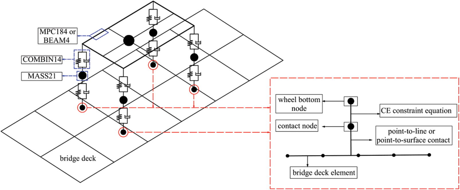
Figure 1: Vehicle-bridge coupled model
To adhere to the power spectral density fitting expression for road surface vibrations recommended by the “Mechanical vibration-Road surface profiles-Reporting of measured data” (GB/T7031-2005), a program was developed using the fast Fourier transform technique and implemented on the MATLAB platform [29]. This program was used to generate samples of road surface roughness for road classes A, B, and C, as illustrated in Fig. 2.

Figure 2: Road surface roughness samples of grades A to C
The established motion equations for the time-varying vehicle-bridge coupled system are expressed as follows:
where
2.2 Realization of Spatiotemporal and Mechanical Effects during Uniform Deceleration Motion of Vehicles
During the process of the uniform variable-speed motion of the vehicle, horizontal acceleration occurs, resulting in the generation of a horizontal inertial force within the vehicle. This inertial force initiates a pitching motion of the vehicle body, leading to a redistribution of the vertical contact forces acting on both the front and rear wheels in conjunction with the bridge deck. To illustrate this phenomenon, a two-axle vehicle undergoing uniform deceleration is considered while moving to the right, as depicted in Fig. 3. In this scenario, where the total mass of the vehicle is denoted as M, the gravitational acceleration is g, the distance from the center of mass (Mc) to the road surface is hc, the horizontal distance from the front wheel center to the center of mass is l1, and the horizontal distance from the rear wheel center to the center of mass is l2, a force analysis of the vehicle and the establishment of equilibrium equations for forces and moments based on the principles of vehicle dynamic equilibrium are conducted. Consequently, the vertical contact forces for the front and rear wheels can be determined as follows:
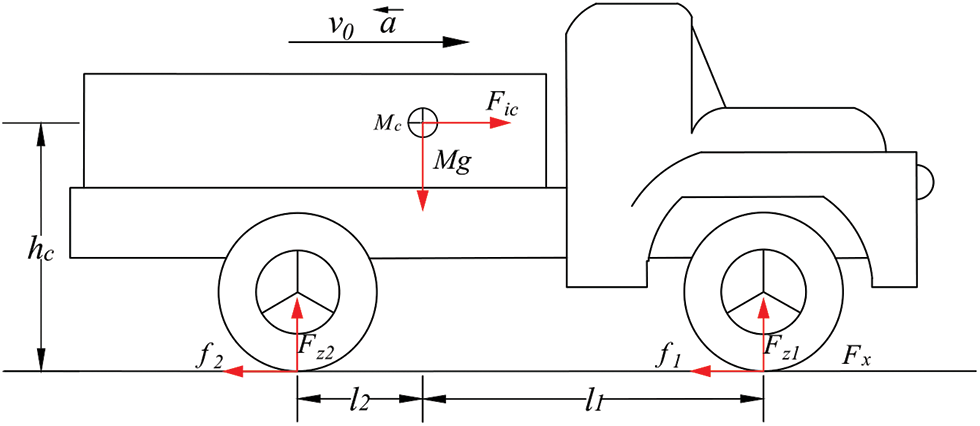
Figure 3: Schematic of forces acting on the vehicle in uniform deceleration motion
When the vehicle undergoes rightward braking, it generates a horizontal inertial force,
During vehicle braking, the wheels undergo three distinct motion states: pure rolling, semi-rolling, semi-reeping, and sliding, which are commonly referred to as wheel locks. In these different states, the distribution of the braking forces between the front and rear wheels also varies. The optimal ratio of the braking force distribution between the front and rear wheels of the vehicle is expected to match the ratio of the vertical loads exerted by the front and rear wheels on the road surface. In such cases, the braking force approaches a critical state of adhesion, resulting in the maximal attainable braking efficiency [30]. Therefore, the relationship between the braking coefficient α (the ratio of the braking force to the vertical contact force) and braking acceleration a can be expressed as
The ground braking forces
The horizontal forces
In comparison with a vehicle in uniform motion, the spatiotemporal and mechanical effects resulting from the uniform deceleration braking motion of the vehicle can be summarized as follows: These effects are subsequently incorporated into the framework of the vehicle-bridge coupled system established using the contact constraint approach. A two-axle vehicle in a planar configuration is taken as an example, as depicted in Fig. 4.

Figure 4: Schematic of a vehicle passing a bridge under uniform deceleration
(1) Along the direction of vehicle motion, when the vehicle initiates deceleration, the longitudinal displacement of vehicle nodes along the bridge within identical temporal substeps differs from that during vehicle motion at a constant velocity. This difference can be expressed through the transition from
(2) From Eqs. (2) and (3), it is evident that the horizontal inertial force
(3) During the uniform deceleration braking process of a vehicle, a forward horizontal inertial force
(4) The transition of the vehicle from a uniform motion state to a steady uniform variable motion state involves an inherent phase of a gradual increase in the magnitude of acceleration, known as the phase of acceleration ascent. Assuming a linear increase in acceleration from 0 during the vehicle braking process [31], this gradual acceleration increase from 0 can be simplified as a non-uniform variable process that increases linearly with time. As illustrated in Fig. 5,

Figure 5: Schematic of the linearly gradual vehicle acceleration transition
In the vehicle-bridge coupled vibration model, it is important to recognize that the wheels may not always be in continuous contact with the individual nodes of the bridge deck throughout the entire travel process. Hence, it is necessary to convert the horizontal forces exerted by the wheels on the bridge deck, represented as Fui, into equivalent nodal loads acting on the bridge deck elements [32]. To illustrate this concept, consider a bridge deck constructed using plate or hexahedral solid elements. Assuming that at a given moment, the i-th wheel is positioned over a specific location within the span of a plate element, the horizontal force exerted by the i-th wheel at this point can be equivalently represented as nodal loads on the plate element by utilizing plate element shape functions. This approach facilitates the application of a horizontal force of the wheel to the bridge deck. As shown in Fig. 6, the wheel applies a horizontal force denoted as Fui to the bridge deck plate element at any position (x, y) within the quadrilateral plate element.
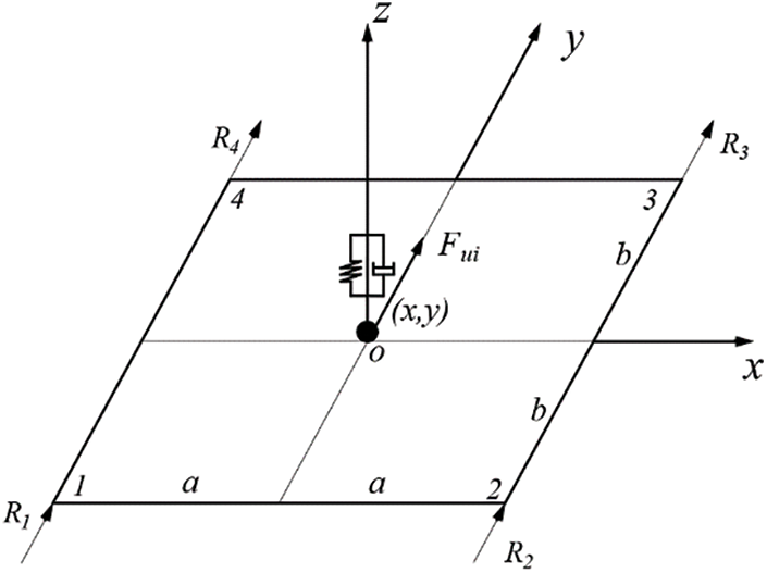
Figure 6: Schematic of equivalent horizontal load on quadrilateral element
The geometric parameters
where x and y are the x- and y-coordinate values of the wheel position in the global coordinate system, respectively; xi and yi are the x- and y-coordinate values of the i-th node of the plate element in the global coordinate system, respectively; and a and b are half the length dimensions of the plate element.
The shape functions in the horizontal direction at each node of the plate element are as follows:
The equivalent horizontal loads at each node of the plate element are as follows:
where [N] is the shape function matrix of the bridge deck element at the contact point of the vehicle-bridge interaction and [T] is the position extension matrix of the contact element, comprising elements with values of 0 and 1.
Expanding on the foundational Eq. (1) of the vehicle-bridge coupled vibration dynamics under uniform motion, and considering the extensive impact of the vehicle’s uniform deceleration effect, the time-varying differential equations of the coupled vibration system considering the effect of uniform deceleration motion of vehicles are as follows:
Using the APDL secondary development platform, a program was created to execute the analysis method for the time-varying system analysis of vehicle-bridge coupled vibrations during uniform deceleration motion. The workflow of this method is illustrated in Fig. 7. The “vehicle motion state determination and application” program module is constructed utilizing the APDL language, as indicated by the red box in Fig. 7. This module is designed to automatically determine whether a vehicle is in a state of uniform motion or deceleration.
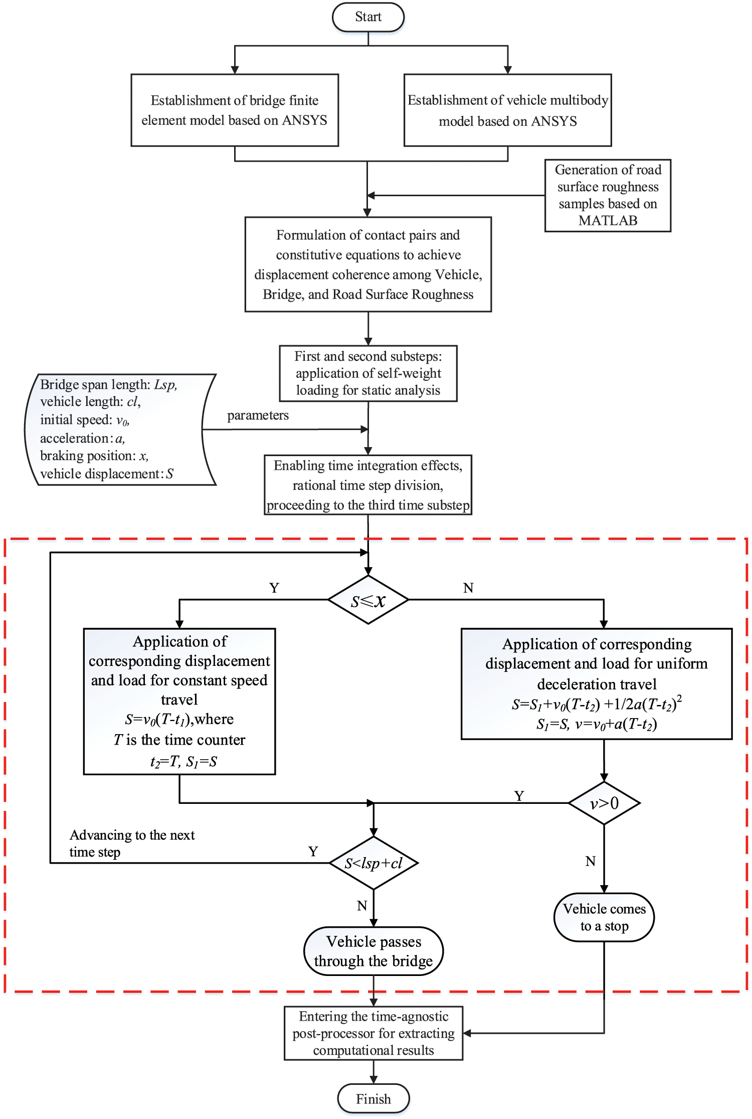
Figure 7: Analysis workflow diagram
To assess the validity of the proposed method outlined in this paper, a numerical analysis of the vehicle-bridge coupled vibration during a vehicle’s uniform deceleration while crossing a bridge was conducted by employing the separation iteration method. The parameters for the vehicle and bridge were adopted from references [33,34]. Scenarios of vehicle-bridge coupled vibration were examined using both the method proposed in this study and the separation iteration method, while a braking vehicle traverses a simply supported beam (or slab) bridge. This comparison validated the reasonability and reliability of the proposed method.
Two distinct vehicle braking conditions were considered in the analysis, the vehicle began with an initial speed of 80 km/h, commenced braking 10 m from the bridge head, and decelerated at a rate of −0.8 g. The vehicle started with an initial speed of 30 m/s, initiated braking 30 m from the bridge head, and decelerated at a rate of −6 m/s². The calculations for these braking scenarios were performed using both the method proposed in this study and the separation iteration method. The results were then compared, and the time-history curves of the vertical displacement at the mid-span of the bridge for both methods are presented in Fig. 8.
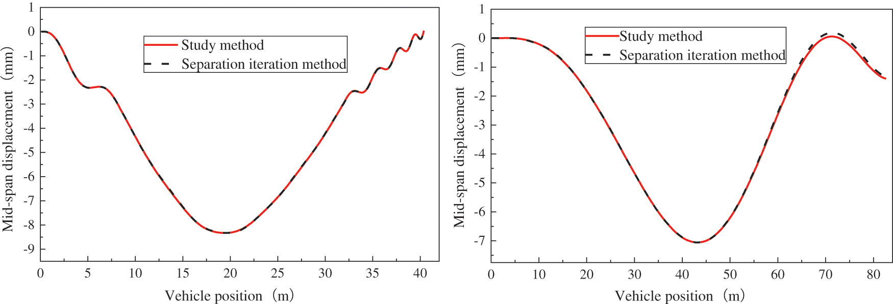
Figure 8: Comparison of bridge mid-span displacement time-history curves during vehicle uniform deceleration crossing
Fig. 8 shows that the time-history curves of the vertical displacement at the mid-span of the bridge, as determined by the method proposed in this study, closely align with those obtained through the separation iteration method. Notably, the peak values of the vertical displacement at the mid-span of the bridge exhibited a remarkable similarity, with a maximum deviation of less than 1%. This observation confirms the applicability and validity of the proposed method.
3 Bridge Overview and Establishment of the Vehicle-Bridge Coupled Model
In the context of an illustrative engineering case, a simply supported assembled steel box girder bridge featuring corrugated steel webs located on a specific national highway in China was examined. This bridge has a design span of 50 m and a single-span width of 16 m, accommodating six dual-lane carriageways designed for a speed limit of 80 km/h. Each span of the bridge consisted of three prefabricated corrugated steel web composite box girders, characterized by a girder height of 3.0 m and a girder width of 5 m. The wet joint width was set to 0.53 m. The top slab thickness of the box girder was 18 cm, whereas the bottom slab thickness ranged from 25 to 45 cm. The corrugated steel web itself has a thickness of 9 mm and an inclination ratio of 1:4, with a wavelength of 1.2 m. Along the longitudinal axis of the bridge, a total of five transverse concrete diaphragms, each with a thickness of 20 cm, are uniformly distributed.
The connection between the corrugated steel web and both the top and bottom concrete slabs was established through embedded connections using structural steel plate studs. Similarly, the connection between the corrugated steel web and the inner concrete lining and transverse diaphragms was achieved using welded studs. The concrete material grade for the composite box girders was designated C50, whereas the material for the corrugated steel webs was Q345 steel. For reference, the elevation arrangement of the composite box girder bridge with corrugated steel webs is shown in Fig. 9. The cross-sectional layout diagram and constructional depiction of the box girder with corrugated steel webs are shown in Figs. 10 and 11, respectively.
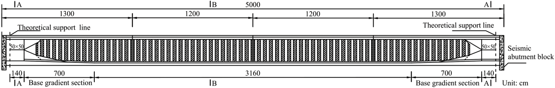
Figure 9: Elevation arrangement diagram of the bridge

Figure 10: Transverse cross-section arrangement diagram of the bridge at the mid-span

Figure 11: Structural diagram of the corrugated steel web
The finite element model of the simply supported box girder bridge with corrugated steel webs was constructed using ANSYS finite element software. Given the structural configuration and loading characteristics of various bridge components, SOLSH190 solid-shell elements were chosen to replicate the behavior of the concrete top and bottom slabs, inner concrete lining, and transverse diaphragms within the box girder. SOLSH190 elements can be used to simulate layered solid structures, and only one element in the thickness direction of the top and bottom plates of the box girder is required during modelling. Therefore, the number of finite elements can be significantly reduced in the model compared to that of conventional solid elements without compromising computational accuracy [35]. In addition, SHELL181 elements were utilized to model corrugated steel webs. The entire bridge was discretized into 27,984 nodes and 18,782 elements. A spatial representation of the finite-element model of the bridge is shown in Fig. 12.

Figure 12: Finite element model of the bridge
Natural frequency analysis of the bridge structure was performed using the Lanczos method. The outcomes encompass the initial ten natural frequencies and their corresponding mode shapes, meticulously documented in Table 1 and visually represented in Fig. 13.

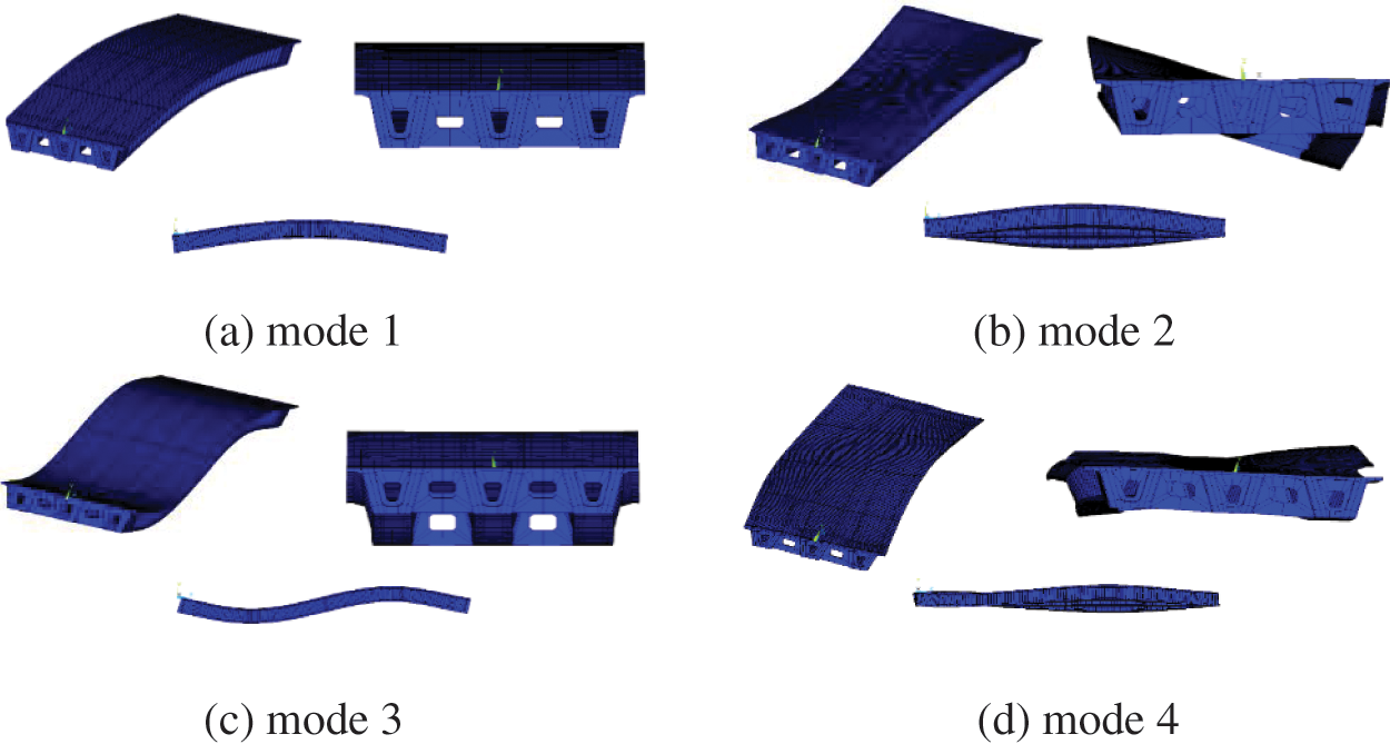
Figure 13: First four modes of bridge vibrations
The analysis presented in Table 1 and Fig. 13 reveals that the bridge primarily exhibited three distinct vibration modes: overall vertical bending, overall lateral bending, and overall torsional vibration. The initial mode observed is the overall vertical bending vibration, followed by the overall torsional vibration and then the lateral bending vibration. This sequence of modes suggests that the vertical bending stiffness of the simply supported box girder bridge with corrugated steel webs is comparatively lower. Furthermore, the torsional vibrations of the bridge occurred earlier than its lateral bending vibrations, indicating that the torsional stiffness of the bridge was lower than its lateral bending stiffness. In the fourth-order lateral bending mode, local torsional vibrations are also present in the main girder flange. Additionally, the seventh-order mode of the bridge corresponds to local torsional vibrations in the main girder flange. This phenomenon can be attributed to the relatively thin corrugated steel webs of the small box girder, resulting in lower torsional stiffness and propensity for local torsional vibrations. Consequently, the overall torsional stiffness of the bridge structure was diminished.
The vehicle model utilized for the vehicle-bridge coupled analysis in this study is the spatial 5-axle vehicle model selected from reference [36] and illustrated in Fig. 14. Within the ANSYS finite element software, a mass-spring-damper model of the spatial 5-axle vehicle was constructed. This model includes a representation of the wheels and vehicle body using the MASS21 mass element. The vehicle suspension was simulated using the COMBIN14 spring-damper element, whereas the vehicle frame was emulated with either MPC184 or rigid beam elements. The connection hanger between the vehicle front and body was modelled using the COMBIN14 spring element. The established finite element model encompassing the coupled vehicle and bridge is shown in Fig. 15.
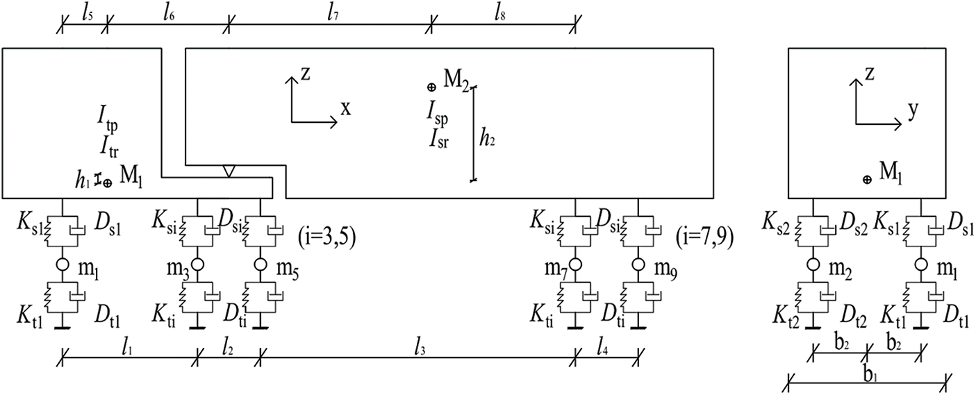
Figure 14: Spatial 5-axle vehicle model
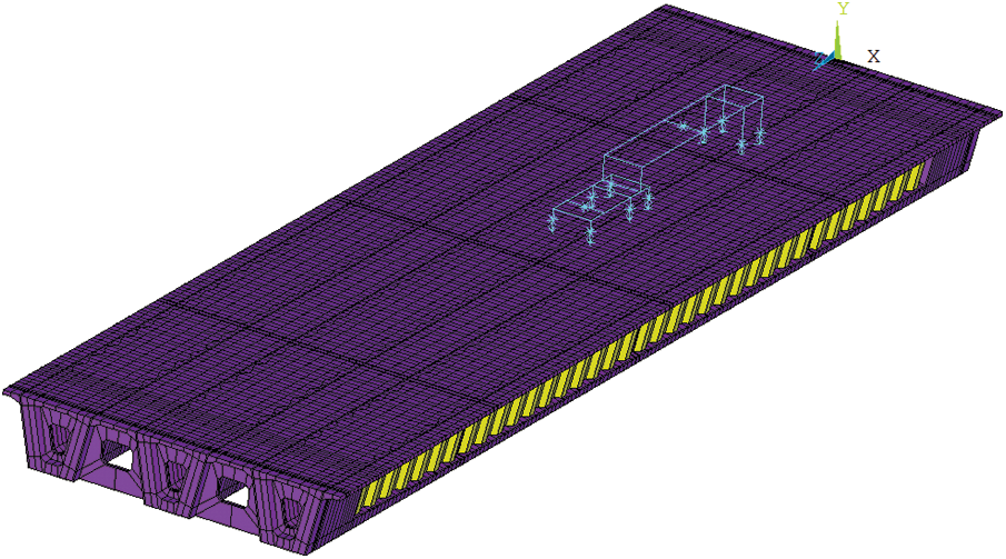
Figure 15: Vehicle-bridge coupled system model
During the uniform variable motion of the spatial 5-axle vehicle model, the spatiotemporal effects were integrated by imposing enforced displacements on each node of the vehicle model at every time step. This was achieved by utilizing the formula for uniform variable motion, where
During the uniform variable motion of the vehicle, the frictional forces exerted by the wheels on the bridge deck were simulated by applying equivalent horizontal forces at the positions of each wheel on the bridge deck at each time step. These equivalent horizontal forces are determined based on the relative proportional distribution of the total frictional force Fu among the vertical contact forces between each wheel and the bridge deck. This distribution is influenced by the static forces exerted by the vehicle’s self-weight and pitch moments Mu1 and Mu2.
4 Influence Analysis of Vehicle Braking on the Impact Factor of Simply Supported Beam Bridges with Corrugated Steel Webs
Utilizing the established vehicle-bridge coupled vibration analysis model, a comprehensive analysis of the vehicle-bridge coupled vibration was carried out in the context of the uniform deceleration motion of the vehicle. By selecting specific lanes for heavy vehicle traffic, along with the identification of critical locations that elicit substantial dynamic responses and impact factors, the observation points for monitoring the bridge dynamic response and impact factor were designated D3 and D5, as depicted in Fig. 16. Subsequently, an in-depth exploration is undertaken to scrutinize the influence patterns of various factors, including the initial vehicle speed, acceleration, braking position, and road roughness grades, on the vertical displacement impact factor at the mid-span of the bridge.

Figure 16: Schematic diagram of measurement point locations
4.1 Effect of Initial Vehicle Speed
To explore the impact of initial vehicle speeds during uniform deceleration braking on the mid-span displacement impact factor of bridges, the following coupled vehicle-bridge vibration analyses were carried out. Based on the highest design vehicle speed requirements for highway bridges and common representative vehicle speeds, initial vehicle speeds of 40, 60, and 80 km/h were considered in the analysis. The vehicles commenced uniform deceleration manoeuvres with accelerations of −2, −4, and −6 m/s², initiated at distances of 10 m (L/5), 20 m (L/5), 30 m (L/5), and 40 m (L/5) from the bridge head. The road surface roughness was classified as Class A. The calculated mid-span displacement impact factors were obtained at locations D3 and D5 along the bridge cross-section. For each deceleration position, the representative impact factor was determined as the average value of

Figure 17: Representative values of the mid-span displacement impact factor for different initial velocities
In Fig. 17, it is evident that the maximum mid-span displacement impact factor for the bridge is 0.244, which closely aligns with the design value of 0.257 under optimal road conditions. Moreover, compared with the displacement impact factor when the vehicle is moving at a constant speed (a = 0), the impact factor undergoes a substantial increase during the deceleration of the vehicle. The results show that the braking action of the vehicle significantly affects bridge vibrations, resulting in a noticeable upsurge in the mid-span displacement impact factor of the bridge. When considering the same braking position and deceleration rate, an increase in the initial vehicle speed leads to a similar trend in the mid-span displacement impact factor, as observed in the case of constant-speed vehicle travel. Specifically, it initially decreases and then increases. When comparing Figs. 17a and 17b, it is apparent that when vehicles with the same initial speed commence braking at the same location, the mid-span displacement impact factor at position D3 of the bridge surpasses that at position D5. Furthermore, both the D3 and D5 mid-span displacement impact factors reached their peak values when the vehicle’s initial speed was 40 km/h.
4.2 Effect of Braking Acceleration
To analyse the influence of vehicle braking acceleration on the mid-span displacement impact factor of the bridge, coupled vehicle-bridge vibration analyses were carried out under various scenarios, where vehicles braked with accelerations of −2, −4, and −6 m/s2 from different positions on the bridge. For various initial vehicle speeds, because the impact patterns of braking accelerations on the displacement impact factor of the bridge are largely similar, the following results under the condition of an initial vehicle speed of 60 km/h are only listed. The time-history curves of the mid-span displacement at D5 for different braking accelerations are shown in Fig. 18. In addition, the mid-span displacement impact factors at locations D3 and D5 for different braking accelerations were determined and are illustrated in Fig. 19.
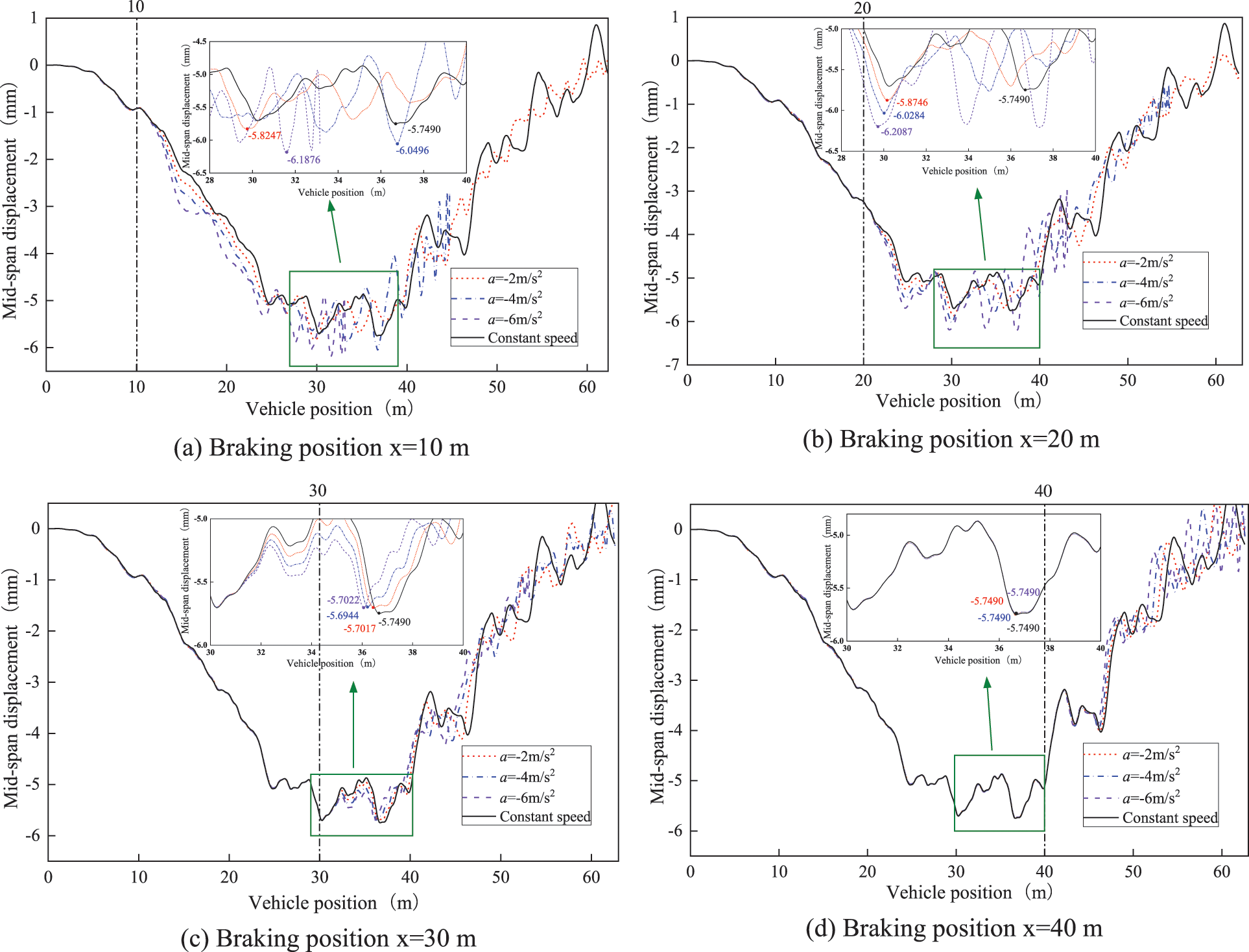
Figure 18: Time history curves of the mid-span displacement at D5 of the bridge under different accelerations
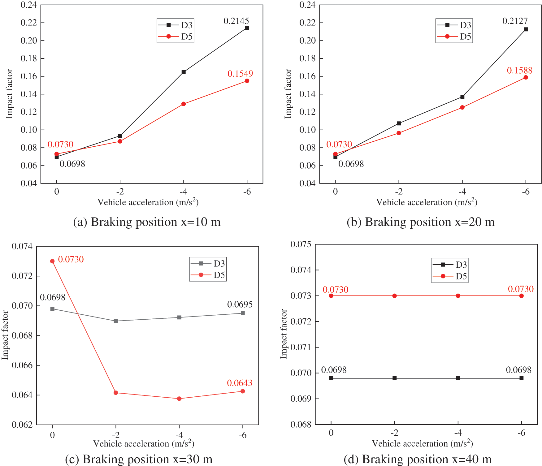
Figure 19: Mid-span displacement impact factors of the bridge under different accelerations
The analysis of Figs. 18a–18c reveals that when the vehicle initiates braking with various acceleration rates at approximately the front half of the span, the peak value of the mid-span displacement response at position D5 of the bridge increases proportionally with the acceleration rate. Furthermore, as the vehicle reaches the same position, the vibration amplitude at the mid-span of the bridge also exhibits an increase corresponding to the acceleration rate. This observation indicates that an increase in braking acceleration significantly amplifies the impact of the vehicle on the bridge. Conversely, as shown in Fig. 18d, when the vehicle starts braking at the rear half of the span, the mid-span displacement of the bridge has already peaked during the vehicle’s constant speed passage through the mid-span. Consequently, as the vehicle moves farther away from the mid-span after this point, the braking action has a minimal impact on the peak value of the mid-span displacement. Therefore, at this stage, different acceleration rates have a limited effect on the mid-span displacement response of the bridge.
The data presented in Fig. 19 reveal that when the vehicle commences braking at positions x = 10 m and x = 20 m, the mid-span displacement impact factors at positions D3 and D5 of the bridge exhibit an increasing trend with the magnitude of braking acceleration. Moreover, they surpass the impact factors observed during constant-speed motion. Notably, when the acceleration reaches −6 m/s², the mid-span displacement impact factors at positions D3 and D5 reach their maximum values, experiencing increases of 204.70% and 117.51%, respectively, compared to the impact factors during constant-speed motion.
In contrast, when the vehicle initiates braking at position x = 30 m, the mid-span displacement impact factors at positions D3 and D5 do not exhibit a clear trend with different acceleration levels; however, overall, they are smaller than the impact factors during constant-speed motion. The forces acting on the mid-span of the bridge are more complex at this specific braking position during deceleration.
Finally, when the vehicle begins braking at position x = 40 m, the mid-span displacement impact factors at positions D3 and D5 remain unchanged with increasing acceleration and are equal to the impact factors observed during constant-speed motion.
Consequently, the variation pattern of the mid-span displacement impact factor for simply supported beam bridges with corrugated steel webs in response to different braking accelerations is contingent on the location of vehicle braking. Specifically, when the vehicle initiates braking at the front half-span of the bridge, both the mid-span displacement response and displacement impact factor at the mid-span demonstrate a continuous increase with higher braking accelerations, with a significant magnitude of amplification. Conversely, when the vehicle brakes at the rear half-span of the bridge and the braking position is situated farther away from the mid-span position, the influence of braking acceleration on the bridge displacement impact factor becomes less pronounced.
4.3 Effect of Vehicle Braking Position
To analyse the influence of vehicle braking positions on the mid-span displacement impact factor of the bridge, coupled vehicle-bridge vibration analyses were carried out. Vehicles were subjected to braking with accelerations of −2, −4, and −6 m/s², initiating braking at distances of 10 m (L/5), 20 m (2 L/5), 30 m (3 L/5), and 40 m (4 L/5) from the bridge head, respectively. For various initial vehicle speeds, because the impact patterns of different braking positions on the displacement impact factor of the bridge are similar, the following results under the condition of an initial vehicle speed of 60 km/h are only listed. The time-history curves of the mid-span displacement at D5 for different braking positions are shown in Fig. 20. The trends of the mid-span displacement impact factors at locations D3 and D5 for different braking positions were determined and are shown in Fig. 21.
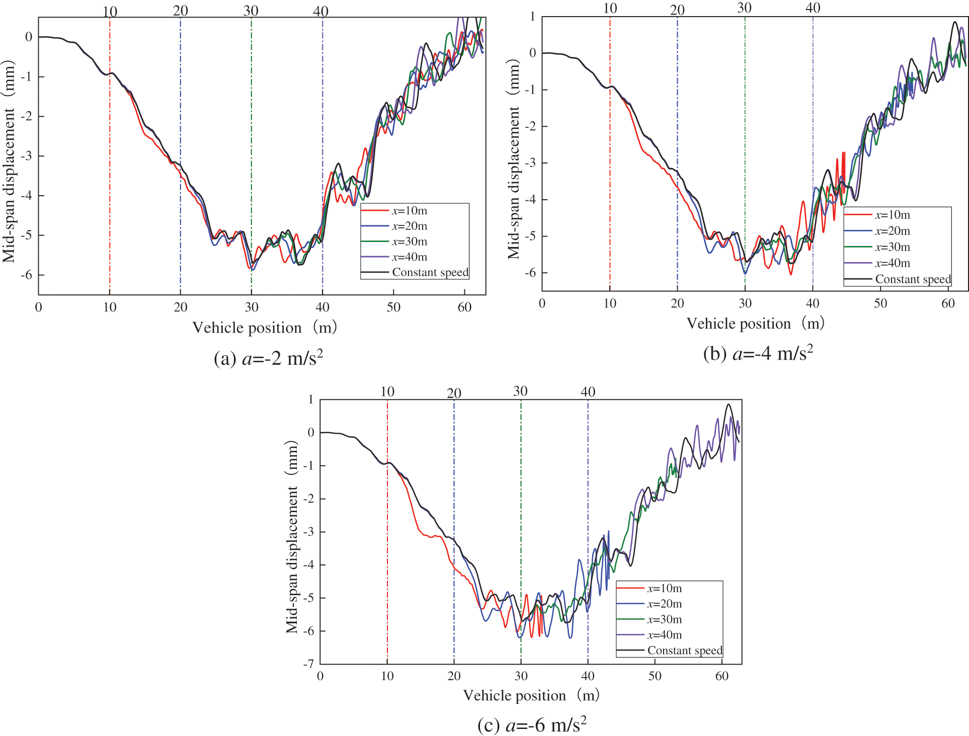
Figure 20: Time history curves of mid-span displacement at D5 of the bridge for different braking positions
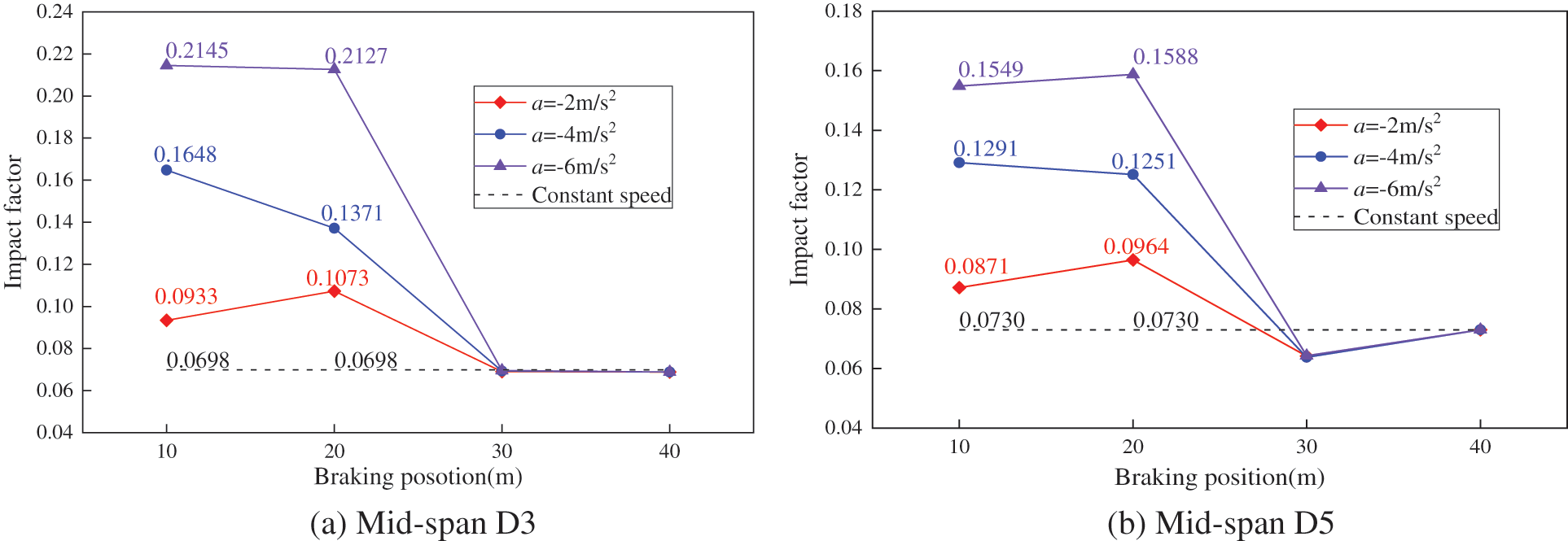
Figure 21: Mid-span displacement impact factors of the bridge for different braking positions
Fig. 20 illustrates a consistent trend of increased mid-span displacement response in the bridge when vehicles initiate braking from different positions. Moreover, within the front half of the span, the mid-span dynamic displacement response of the bridge is amplified as the vehicle’s braking position approaches the bridge’s mid-span.
Fig. 21 reveals that the mid-span displacement impact factors at positions D3 and D5 of the bridge attain their maximum values when the vehicle initiates braking in the front half of the span. Specifically, the impact factors are 0.2145 and 0.1588, respectively, representing a two- to threefold increase compared to the mid-span displacement impact factors during constant-speed driving. When the vehicle commences braking in the rear half of the span, the mid-span displacement impact factors at positions D3 and D5 experience a significant reduction, nearly approximating the impact factors observed during constant-speed driving. This phenomenon can be attributed to the fact that during the initial phase, when the vehicle travels at a constant speed through the mid-span, the mid-span displacement response of the bridge has already reached its peak value. Consequently, the braking action in the rear half of the span exerted a minimal influence on the peak mid-span displacement response.
4.4 Effect of Road Surface Roughness
To explore the influence of road surface roughness on the mid-span displacement impact factor of bridges during the uniform deceleration travel of vehicles, analyses were conducted on bridge decks with different road surface roughness grades: A, B, and C. Vehicles with an initial speed of 60 km/h and a deceleration of −4 m/s² initiated braking from a distance of 20 m from the bridge head until it stopped. Vehicle-bridge interaction vibration analyses were conducted under these conditions. The obtained mid-span displacement time-history curves and mid-span displacement impact factors for different road surface grades are presented in Figs. 22 and 23, respectively. The mid-span displacement impact factors during both steady vehicle travel and uniform deceleration for different road surface grades are listed in Table 2.
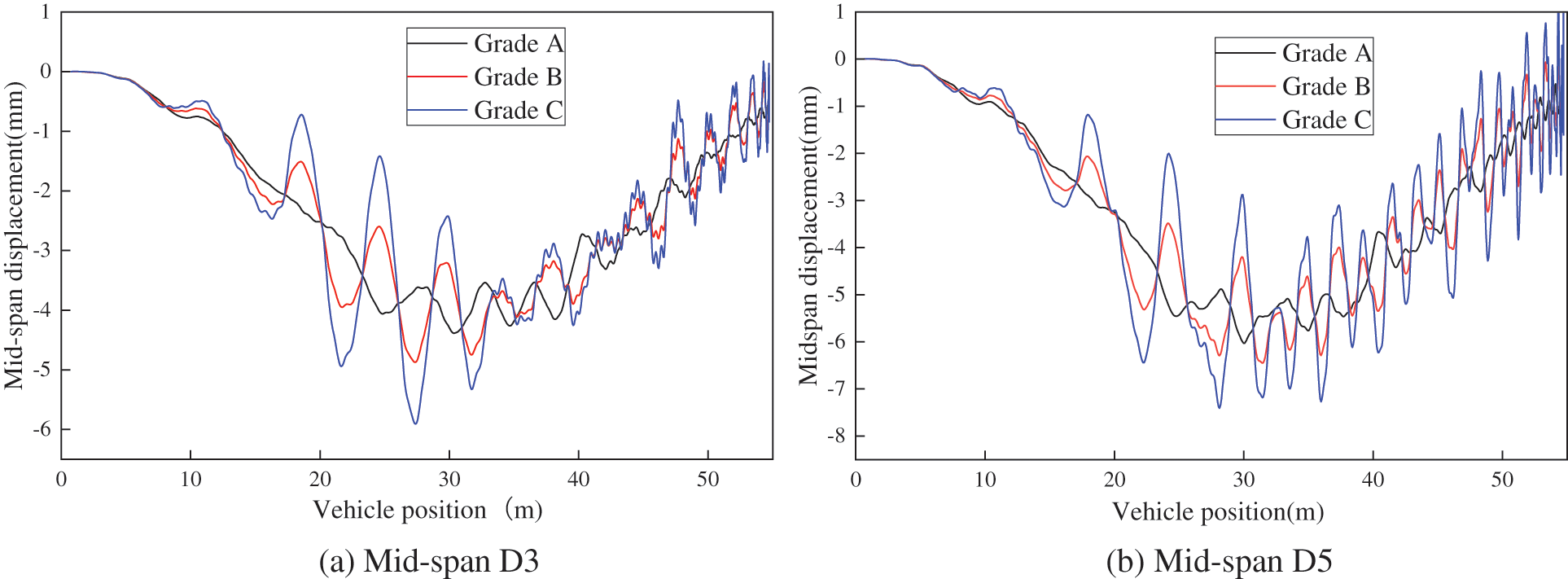
Figure 22: Time history curves of mid-span displacement at the bridge under different road surface grades
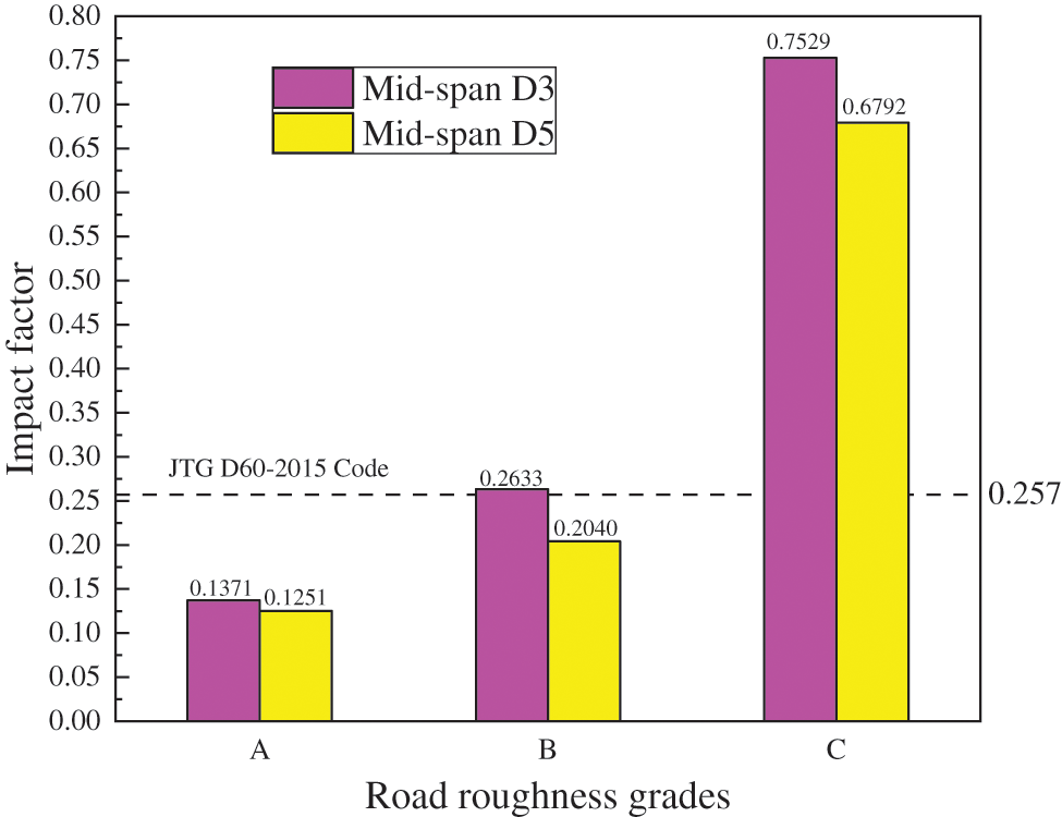
Figure 23: Mid-span displacement impact factors of the bridge under different road roughness grades

Figs. 22 and 23 clearly demonstrate a substantial increase in the mid-span displacement dynamic response of the bridge as the road roughness grades increase. Notably, at position D3 of the mid-span, the displacement impact factor for road roughness grade B has already surpassed the design value stipulated by the regulations. This observation suggests that even under relatively favorable road conditions (road roughness grade B), the vehicle’s braking action induces notable vertical vibrations in the bridge.
Table 2 reveals that, overall, as the road roughness grade increases, the mid-span displacement impact factor during both constant-speed and uniform-deceleration motions progressively increases. Additionally, it is noteworthy that the displacement impact factors during braking consistently surpass those during constant-speed motions. However, as the grade of road roughness increases, the extent of this augmentation diminishes significantly. At road roughness grade C, the increment in the displacement impact factor ranges from approximately 7.47% to 9.35%. This observation suggests that when road conditions deteriorate, the impact of vehicle braking behavior on the displacement impact factor is relatively modest compared to the predominant influence of the road roughness grade, which exerts a more substantial effect on the displacement impact factor than the vehicle’s uniform deceleration braking action.
The observed influence pattern of vehicle braking on the dynamic response and impact factor of corrugated steel web girder bridges in this study generally aligns with the impact pattern of vehicle braking on simply supported concrete bridges reported in [37]. However, a notable distinction exists in that for corrugated steel web girder bridges, the amplification effect of bridge vibration due to uniform deceleration vehicle motion is more pronounced than that of uniform motion. Upon comprehensive analysis and comparison of the data with reference [37], it becomes apparent that, for corrugated steel web girder bridges, the growth rate of the displacement impact factors induced by vehicle braking is approximately 1.5 times greater than the growth rate for similarly spanned simply supported concrete bridges. This result shows that corrugated steel web girder bridges exhibit higher susceptibility to larger vibrations resulting from vehicle braking.
4.5 Analysis of Factors Leading to Increased Impact Factors
Based on the calculations presented above, it is evident that the mid-span displacement and impact factor of the bridge during the uniform deceleration braking of the car exceed those observed during uniform motion. To further investigate the underlying reasons for the amplified mid-span dynamic displacement and impact factor of the bridge during uniform deceleration braking scenarios, a comprehensive analysis of the vehicle-bridge coupled vibrations was undertaken. This analysis was conducted under conditions where the vehicle initiates braking at a distance of 20 m from the bridge head, with an initial speed of 60 km/h and deceleration of −4 m/s². The road surface roughness grade was classified as Grade A. Three distinct scenarios were considered to assess the effects: (1) “uniform deceleration motion only,” (2) “uniform deceleration motion with pitching moment,” and (3) “uniform deceleration motion with pitching moment and frictional forces.” The mid-span displacement response of the bridge was computed for each scenario. The resulting time history curves of the mid-span displacement for the three scenarios are presented in Fig. 24. The impact factors of mid-span displacement were determined for these three scenarios and compared against the impact factor of mid-span displacement during uniform speed vehicular motion, as presented in Table 3. Furthermore, an in-depth analysis was performed to evaluate the individual contributions of uniform deceleration motion, pitching moment, and frictional forces between the wheels and bridge deck to the enhancement of the mid-span impact factor. The contribution ratios of these three effects are shown in Fig. 25.

Figure 24: Time history curves of the mid-span displacement of the bridge under three different conditions

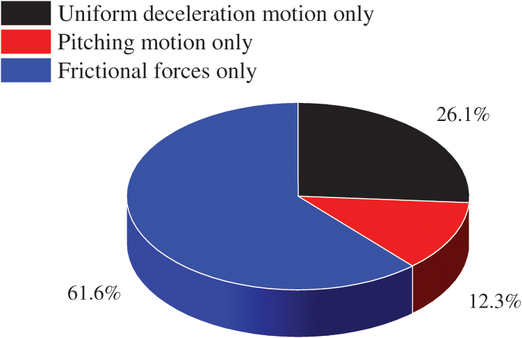
Figure 25: Contribution ratios of increased impact factors due to three different effects
Note: Contribution ratio = increase rate of impact factor for each effect/total increase rate of impact factors due to three effects.
From Figs. 24 and 25 and the data presented in Table 3, a clear progression emerges. The transition from “Uniform deceleration motion only” to “Uniform deceleration motion with pitching motion” and subsequently to “Uniform deceleration motion with pitching motion and frictional forces” results in successive increases in both the peak displacement response and impact factor of the bridge’s displacement time history curves. This observation underscores the cumulative mechanical effects introduced during vehicle braking, specifically the pitching moment and frictional interaction, which collectively contribute to the amplification of the mid-span dynamic displacement response of the bridge.
The presence of the pitching moment creates an asymmetrical load distribution between the front and rear axles, leading to an augmentation of the vertical contact force exerted by the wheels closer to the mid-span position. Consequently, the mid-span displacement of the bridge experiences a corresponding increase. Furthermore, the horizontal frictional forces between the wheels and the bridge deck generate a concurrent rotational moment about the centroid of the bridge section. This moment, which is evident during the initial half-span braking phase, further accentuates the mid-span displacement of the bridge. The synthesized results from these analyses highlight the cumulative nature of these mechanical effects on the mid-span dynamic response of the bridge during braking events.
In the context of vehicle-bridge coupled vibration analysis, particularly when considering braking scenarios, it is essential to recognize that the contribution of frictional forces generated by the wheels during a vehicle’s uniform deceleration motion is the most significant factor, surpassing the influence of the vehicular pitching moment and the effect associated with uniform deceleration motion. Subsequently, the impact of the uniform deceleration motion holds the next grade of importance, whereas the contribution of the pitching moment has the lowest magnitude. Consequently, when vehicle-bridge coupled vibration analysis with a focus on braking scenarios is conducted, it is imperative to not underestimate the influence of the frictional forces generated by the wheels during a vehicle’s uniform deceleration motion.
In this paper, a novel vehicle-bridge coupled vibration analysis method is presented that specifically addresses the effects of vehicle braking. The method was implemented using programming within the ANSYS finite element software and its APDL secondary development platform, enabling a comprehensive analysis and solution of uniform deceleration vehicle-bridge coupled vibrations. The ramifications of several key factors, including the initial vehicle speed, braking acceleration, braking location, and road surface roughness, on the mid-span displacement and impact factor of corrugated steel web girder bridges were analysed in this study. The principal conclusions drawn from this investigation are as follows:
(1) In comparison with the condition of uniform vehicular motion, the spatiotemporal and mechanical consequences resulting from vehicle braking behavior magnify the mid-span displacement response and its impact factor for a simply supported girder bridge with a corrugated steel web. This scenario poses a challenge for bridge structures. Notably, the preeminent influence is exerted by the frictional forces between the vehicle wheels and the bridge deck. This effect holds paramount significance within the context of a vehicle-bridge coupled vibration analysis that considers vehicle braking.
(2) When the vehicle undergoes uniform deceleration while traversing the bridge at various initial velocities, the impact factor of the mid-span displacement exhibits a trend of initially decreasing and then increasing as the initial velocity increases. This trend aligns with the variations observed under uniform motion conditions. When the vehicle initiates braking around the first half-span of the bridge, the impact factor of the mid-span displacement significantly surpasses that observed during uniform motion, consistently increasing with higher braking acceleration, resulting in a substantial increment. However, when the vehicle brakes around the latter half-span of the bridge, the mid-span displacement impact factor approximates that of uniform motion conditions, becoming independent of the braking position and braking acceleration magnitude.
(3) The mid-span displacement of the bridge and impact factor progressively increase with an increase in the road surface roughness grade. Under Grade B road surface roughness conditions, the displacement impact factor during uniform deceleration exceeds the prescribed design limits. Furthermore, as the road surface roughness grade increases, its influence on the mid-span impact factor of the bridge becomes more pronounced, surpassing the effects stemming from vehicular braking dynamics.
(4) In comparison to the impact of vehicle braking on the dynamic response of a simply supported concrete bridge, it is noteworthy that vehicle braking tends to induce larger dynamic responses in corrugated steel web girder bridges. Therefore, when designing corrugated steel web girder bridges, it is advisable to consider the outcomes of vehicle-bridge coupled vibration analysis considering the vehicle braking effects. Based on the calculated values of the impact factors according to the standard, it is recommended to appropriately increase the impact factor values to ensure the safety of the bridge during the operational phase.
Acknowledgement: This work is supported by the Henan Provincial Science and Technology Research Project.
Funding Statement: This work is supported by the Henan Provincial Science and Technology Research Project under Grant (152102310295).
Author Contributions: The authors confirm contribution to the paper as follows: study conception and design: Yan Wang; data collection: Siwen Li, Na Wei; analysis and interpretation of results: Yan Wang, Siwen Li; draft manuscript preparation: Yan Wang, Siwen Li, Na Wei. All authors reviewed the results and approved the final version of the manuscript.
Availability of Data and Materials: All data, models, or code that support the findings of this study are available from the corresponding author upon reasonable request.
Conflicts of Interest: The authors declare that they have no conflicts of interest to report regarding the present study.
References
1. Jiang, R. J., Wu, Q. M., Xiao, Y. F., Peng, M. L., Tat Kwong Au, F. et al. (2023). The shear lag effect of composite box girder bridges with corrugated steel webs. Structures, 48, 1746–1760. https://doi.org/10.1016/j.istruc.2023.01.031 [Google Scholar]
2. Chen, Y. T., Xu, J., Ding, Y. (2020). Mechanical performance analysis of corrugated steel webs (CSWs) PC box girder with different cell numbers. Journal of Jiangsu University (Natural Science Edition), 41(6), 726–730 (In Chinese). https://doi.org/10.3969/j.issn.1671-7775.2020.06.016 [Google Scholar] [CrossRef]
3. Zhou, C., Li, L. F., Wang, J. Q. (2020). Modified bar simulation method for shear lag analysis of non-prismatic composite box girders with corrugated steel webs. Thin-Walled Structures, 155, 106957.1–106957.13. https://doi.org/10.1016/j.tws.2020.106957 [Google Scholar] [CrossRef]
4. Li, L. F., Zhou, C., Wang, L. H. (2018). Distortion analysis of non-prismatic composite box girders with corrugated steel webs. Journal of Constructional Steel Research, 147, 74–86. https://doi.org/10.1016/j.jcsr.2018.03.030 [Google Scholar] [CrossRef]
5. Li, Q. B., Zhou, M. (2023). Study on the natural frequency of box girders with corrugated steel webs. Journal of Constructional Steel Research, 211, 108123. https://doi.org/10.1016/j.jcsr.2023.108123 [Google Scholar] [CrossRef]
6. Li, Y. S., Dai, Q. N., Zhang, Y. L., Liu, C. X. (2021). Free vibration performance of curved composite box-girders with corrugated steel webs. Journal of Constructional Steel Research, 186, 106882. https://doi.org/10.1016/j.jcsr.2021.106882 [Google Scholar] [CrossRef]
7. Jiang, L. Z., Chai, X., Feng, Y. L., Zhou, W. B., Zhang, Y. T. et al. (2018). Dynamic characteristic study of composite box beam with corrugated webs considering interface slip and shear deformation. IOP Conference Series: Earth and Environmental Science, 189(2), 22015. https://doi.org/10.1088/1755-1315/189/2/022015 [Google Scholar] [CrossRef]
8. Cao, L., Liu, J. P., Chen, Y. F. (2018). Theoretical and numerical study on the natural frequencies of bridges with corrugated steel webs. Structures, 15, 224–231. https://doi.org/10.1016/j.istruc.2018.07.005 [Google Scholar] [CrossRef]
9. Zheng, T. (2019). Dynamic characteristics and seismic response study of PC composite continuous girder bridge with corrugated steel webs (Master Thesis). Southeast University, China. https://doi.org/10.27014/d.cnki.gdnau.2019.002654 [Google Scholar] [CrossRef]
10. Shi, F., Wang, D. S., Chen, L. (2021). Study of flexural vibration of variable cross-section box-girder bridges with corrugated steel webs. Structures, 33, 1107–1118. https://doi.org/10.1016/j.istruc.2021.05.004 [Google Scholar] [CrossRef]
11. Zheng, S. M. (2016). Study on dynamic performance of PC composite box girder bridge with corrugated steel webs (Master Thesis). Southeast University, China. https://doi.org/10.7666/d.Y3140883 [Google Scholar] [CrossRef]
12. Moon, J., Ko, H., Sung, I., Lee, H. (2015). Natural frequency of a composite girder with corrugated steel web. Steel and Composite Structures, 18, 255–271. https://doi.org/10.12989/scs.2015.18.1.255 [Google Scholar] [CrossRef]
13. Kong, X., Luo, K., Ji, W., Tang, Q. Y., Deng, L. (2022). Study on dynamic characteristics of an improved composite box girder with corrugated steel webs. Journal of Bridge Engineering, 27(6). https://doi.org/10.1061/(ASCE)BE.1943-5592.0001877 [Google Scholar] [CrossRef]
14. Ji, W., Deng, L., He, W., Liu, S. Z., Lin, P. Z. (2017). Local and global impact factors analysis for PC box girder bridges with corrugated steel webs. Journal of Vibration and Shock, 36(8), 22–28 (In Chinese). https://doi.org/10.13465/j.cnki.jvs.2017.08.004 [Google Scholar] [CrossRef]
15. Mao, Y. N., Ma, C., Liu, S. Z., Li, L. Y. (2023). Study on the dynamic response of composite box girder bridges with corrugated steel webs. Advances in Civil Engineering, 2023, 5104132. https://doi.org/10.1155/2023/5104132 [Google Scholar] [CrossRef]
16. Shi, J. Q. (2022). Study on dynamic characteristics and impact coefficient of curved corrugated steel plate-concrete composite beam bridge (Master Thesis). Lanzhou Jiaotong University, China. https://doi.org/10.27205/d.cnki.gltec.2022.000825 [Google Scholar] [CrossRef]
17. Yu, H. F. (2022). Study on coupled vehicle-bridge vibration of corrugated steel plate-concrete composite beam bridge based on UM simulation (Master Thesis). Lanzhou Jiaotong University, China. https://doi.org/10.27205/d.cnki.gltec.2022.000934 [Google Scholar] [CrossRef]
18. Azimi, H., Galal, K., Pekau, O. A. (2013). A numerical element for vehicle-bridge interaction analysis of vehicles experiencing sudden deceleration. Engineering Structures, 49, 792–805. https://doi.org/10.1016/j.engstruct.2012.12.031 [Google Scholar] [CrossRef]
19. Deng, L., Wang, F., He, W. (2015). Dynamic impact factors for simply-supported bridges due to vehicle braking. Advances in Structural Engineering, 18(6), 791–801. https://doi.org/10.1260/1369-4332.18.6.791 [Google Scholar] [CrossRef]
20. Yang, T. T., Li, Y., Li, Q. L. (2020). Dynamic performance analysis of substructure for concrete girder bridges under vehicle braking. Journal of Railway Science and Engineering, 17(3), 637–644 (In Chinese). https://doi.org/10.19713/j.cnki.43-1423/u.T20190460 [Google Scholar] [CrossRef]
21. Liu, H. J., Han, W. S., Liu, N., Gao, Y., Han, X. B. (2020). Dynamic evolution of stochastic vehicle flow on bridge under braking conditions and analysis of vehicle-bridge coupled vibration. China Journal of Highway and Transport, 33(4), 76–88 (In Chinese). https://doi.org/10.19721/j.cnki.1001-7372.2020.04.008 [Google Scholar] [CrossRef]
22. Chen, S. S., Lou, H., Gui, S. R. (2020). Dynamic response of curved continuous girder bridge under vehicle braking. Journal of Civil and Environmental Engineering, 42(2), 95–106 (In Chinese). https://doi.org/10.11835/j.issn.2096-6717.2019.153 [Google Scholar] [CrossRef]
23. Chen, X. D. (2019). Coupled vibration analysis of vehicle-bridge for corrugated steel webs box girder bridge based on contact constraint method (Master Thesis). Chongqing University, China. https://doi.org/10.27670/d.cnki.gcqdu.2019.002900 [Google Scholar] [CrossRef]
24. Zhou, R. J., Wang, Y., Chen, H. (2022). Analysis of vehicle-bridge coupled vibration of long-span curved truss bridge in service. Journal of Vibration Engineering, 35(1), 103–112 (In Chinese). https://doi.org/10.16385/j.cnki.issn.1004-4523.2022.01.011 [Google Scholar] [CrossRef]
25. Shi, Y., Song, Y. F., Sun, H., Zhou, X. P. (2010). Dynamic analysis method of vehicle-bridge coupling for complicated bridges based on ANSYS. Journal of Tianjin University, 43(6), 537–543 (In Chinese). https://doi.org/10.3969/j.issn.0493-2137.2010.06.012 [Google Scholar] [CrossRef]
26. Fang, X. Q., Ma, H. W., Zhu, C. S. (2023). Non-local multi-fields coupling response of a piezoelectric semiconductor nanofiber under shear force. Mechanics of Advanced Materials and Structures. https://doi.org/10.1080/15376494.2022.2158503 [Google Scholar] [CrossRef]
27. Fang, X. Q., He, Q. L., Ma, H. W., Zhu, C. S. (2023). Multi-field coupling and free vibration of a sandwiched functionally-graded piezoelectric semiconductor plate. Applied Mathematics and Mechanics-English Edition, 44(8), 1351–1366. https://doi.org/10.1007/s10483-023-3017-6 [Google Scholar] [CrossRef]
28. Wang, X. M. (2014). Structural dynamics analysis and application with ANSYS (In Chinese). Beijing, China: China Communications Press. [Google Scholar]
29. Liu, X. D., Deng, Z. D., Gao, F. (2003). Research on the method of simulating road roughness numerically. Journal of Beijing University of Aeronautics and Astronautics, 29(9), 843–846 (In Chinese). https://doi.org/10.13700/j.bh.1001-5965.2003.09.021 [Google Scholar] [CrossRef]
30. Lei, T. F. (2007). Simulation study on vehicle brake performance based on road conditions (Master Thesis). Harbin Institute of Technology, China. https://doi.org/10.7666/d.D273268 [Google Scholar] [CrossRef]
31. Radhey, K. G., Rupert, W. T. (1980). Vehicle braking on highway bridges. Journal of the Engineering Mechanics Division, 106(4), 641–658. [Google Scholar]
32. Zeng, P. (2004). Finite element analysis and applications (In Chinese). China: Tsinghua University Press. [Google Scholar]
33. Liu, S. Z. (2015). Study on coupled vibration of two-layer highway steel truss bridge with vehicle-bridge interaction (Ph.D. Thesis). Chang’an University, China. https://doi.org/10.7666/d.D749427 [Google Scholar] [CrossRef]
34. Henchi, K., Fafard, M., Talbot, M., Dhatt, G. (1998). An efficient algorithm for dynamic analysis of bridgesunder moving vehicles using a coupled modal and physical components approach. Journal of Sound and Vibration, 212(4), 663–683. https://doi.org/10.1006/jsvi.1997.1459 [Google Scholar] [CrossRef]
35. Wang, X. M., Li, Y. Q., Xu, H. W. (2011). Structural analysis element and application with ANSYS (In Chinese). Beijing, China: China Communications Press. [Google Scholar]
36. Deng, L., Duan, L. L., He, W., Ji, W. (2018). Study on vehicle model for vehicle-bridge coupling vibration of highway bridges in China. China Journal of Highway and Transport, 31(7), 92–100 (In Chinese). [Google Scholar]
37. Deng, L., Wang, F. (2015). Study of the dynamic responses and impact factors of simply-supported prestressed concrete girder bridges due to vehicle braking. Journal of Hunan University (Natural Sciences), 42(9), 52–58 (In Chinese). https://doi.org/10.3969/j.issn.1674-2974.2015.09.007 [Google Scholar] [CrossRef]
Cite This Article
 Copyright © 2024 The Author(s). Published by Tech Science Press.
This work is licensed under a Creative Commons Attribution 4.0 International License , which permits unrestricted use, distribution, and reproduction in any medium, provided the original work is properly cited.
 Downloads
 Citation Tools