
 Submit a Paper
 Propose a Special lssue
 Open Access
ARTICLE

Research on Optimal Preload Method of Controllable Rolling Bearing Based on Multisensor Fusion
1 School of Mechanical and Electrical Engineering, Anhui University of Science and Technology, Huainan, 232001, China
2 School of Optical and Electronic Information, Suzhou City University & Suzhou Key Laboratory of Biophotonics, Suzhou, 215104, China
3 State Key Laboratory for Manufacturing Systems Engineering, Xi'an Jiaotong University, Xi'an, 710054, China
* Corresponding Author: Yasheng Chang. Email:
(This article belongs to the Special Issue: Computer-Aided Uncertainty Modeling and Reliability Evaluation for Complex Engineering Structures)
Computer Modeling in Engineering & Sciences 2024, 139(3), 3329-3352. https://doi.org/10.32604/cmes.2024.046729
Received 12 October 2023; Accepted 28 December 2023; Issue published 11 March 2024
 View Full Text
 Download PDF
Abstract
Angular contact ball bearings have been widely used in machine tool spindles, and the bearing preload plays an important role in the performance of the spindle. In order to solve the problems of the traditional optimal preload prediction method limited by actual conditions and uncertainties, a roller bearing preload test method based on the improved D-S evidence theory multi-sensor fusion method was proposed. First, a novel controllable preload system is proposed and evaluated. Subsequently, multiple sensors are employed to collect data on the bearing parameters during preload application. Finally, a multisensor fusion algorithm is used to make predictions, and a neural network is used to optimize the fitting of the preload data. The limitations of conventional preload testing methods are identified, and the integration of complementary information from multiple sensors is used to achieve accurate predictions, offering valuable insights into the optimal preload force. Experimental results demonstrate that the multi-sensor fusion approach outperforms traditional methods in accurately measuring the optimal preload for rolling bearings.Keywords
Nomenclature
| dm | Pitch circle diameter |
| D | Ball or roller diameter |
| nm | Ball or roller track speed |
| nr | The speed at which a ball or roller rotates around its own axis |
| Mg | Gyroscopic moment |
| Pd | Radial clearance |
| q | Roller/raceway unit length load |
| Q | Ball or roller normal load |
| Qa | Axial load on a ball or roller |
| Qr | Radial load on a ball or roller |
| Qia | Ball thrust load |
| Contact angle | |
| Ball stance angle | |
| Displacement or contact deformation | |
| J | Moment of inertia |
| Angular velocity of rotation | |
| Ball or roller track speed | |
| The speed at which the ball or roller rotates around its own axis | |
| Angular spacing between rolling elements |
As a basic industrial component, bearings reflect industrial development [1–3]. The bearing preload is a crucial mechanical connection technique that establishes a robust link between the shaft and bearing by applying an appropriate pressure or tension. It effectively minimises clearance, enhances bearing rigidity and precision, reduces operational vibrations and noise, improves the load capacity of the machine, and ensures stable machinery operation [4,5].
Bearing preloads can be applied in various ways, such as electromagnetic control, hydraulic control, and centrifugal force control [6–9]. The mechanical control method offers the benefits of automation and stability, enabling more precise torque and position control while providing a consistent control torque. For instance, Tian et al. [10] used a fixture equipped with a pressure sensor to study the influence of a preload on the nonlinear dynamic response of typical bolt cantilever structures through finite element analysis. The hydraulic preload control method is primarily employed for large structures because of its high accuracy and ability to perform a wide range of torque adjustments. Xu et al. [11] studied the temperature rise in the outer ring of a bearing under varying preload and speed conditions by implementing hydraulic preload control. However, notably, this method entails higher equipment costs and requires specific operational and maintenance requirements. The centrifugal force preload control method offers advantages such as no additional energy consumption and uniform loading. However, it is dependent on the rotating equipment and has limitations in terms of the preload torque that can be achieved. Choi et al. [12] used the centrifugal force and rubber pressure to enhance the preload force and proposed an elbow joint mechanism for accommodating variable preloads. Considering the test conditions and requirements, an enhanced mechanical preloading method was employed for the experiments. In contrast to conventional mechanical preloading methods, which typically involve hardware replacement to modify the preload size, this test allows for the direct real-time adjustment of the preload magnitude while facilitating simultaneous observation and recording. Notably, hardware improvements and the integration of multisensor fusion and field-programmable gate array (FPGA) contribute to improved precision and accuracy of the test [13,14].
A data-driven approach is one that analyzes and leverages large amounts of data to drive problem-solving and decision-making, and deep learning and neural networks are typical data-driven approaches. With the widespread application of deep learning technology and the development of transfer learning and self-supervised learning, data-driven methods have become more and more important in industrial applications [15]. However, it also has limitations such as data bias and limited data generalization ability.
Multi-sensor fusion is widely used in industrial system monitoring, fault diagnosis, spatial positioning, logistics management and other fields. By fusing data from multiple sensors, the accuracy and reliability of information can be improved, which in turn can achieve more accurate measurement and sensing results, providing important support for efficient data processing and decision-making [16,17]. Table 1 describes the mainstream methods of multi-sensor fusion and their advantages and disadvantages.

Lee et al. [18] proposed a centralised fusion algorithm for sensor systems along with a filter algorithm particularly designed for distributed sensor systems. The study concluded that this approach yielded higher effectiveness and accuracy than using a single sensor. Yu et al. [19] proposed a single-sensor network and a multisensor network and conducted a comparative analysis to validate the superiority of the multisensor network. Furthermore, they extensively discussed the optimal placement of multiple sensors. Peng et al. [20] proposed an improved Dempster-Shafer (D-S) synthesis formula based on the concept of evidence information and focus element generated by it and applied it to multisensor information fusion technology. Zhang et al. [21] proposed an asynchronous track fusion algorithm with information feedback, which was combined with a target quality management model for weight allocation to improve the performance of an asynchronous multisensor fusion system. These studies illustrated the feasibility and advantages of multisensor fusion. Therefore, a multisensor fusion method was selected to analyse the bearing preloads.
In this article, a variety of sensors are used to capture signals such as sound, vibration, temperature, and torque. When the system works after receiving the influence of preload, compared with normal operation, the generated parameters such as sound vibration and temperature rise will change due to the change of force. Torque is different from other signals, the change of torque will change the initial state of the system, and the preload force can be applied to the system in different situations, as a variable group to obtain more data, so that the experimental accuracy and stability are improved. In this paper, the improved D-S evidence theory method is used to process the data, and the results are more accurate and stable than those of the traditional methods.
To the best of our knowledge, predicting the bearing preload using multisensor fusion is a relatively new method, and the contributions of the current study are as follows:
1) A new type of precision controllable mechanical preload test bench was established, and the mechanical preload data was measured in various aspects and scales.
2) An improved multisensor fusion method is proposed to analyse and predict the measured bearing preload and propose a more accurate optimal bearing preload.
The remainder of this paper is organised as follows: The second section introduces the principle of bearing preload and the influence of mechanical preload, introduces the new controllable preload test bench used in the third section, analyses and predicts the experimental data, and uses deep learning to fit the data to ensure the accuracy of the investigation. Finally, the paper is summarised, and future research is discussed.
2.1 Rolling Bearing Load Analysis
Various factors generate a dynamic load between the rolling elements and bearing raceways. The dynamic loads are relatively small at medium and low speeds compared with the external forces acting on the balls or rollers. However, at high speeds, dynamic loads such as centrifugal forces and gyroscopic moments significantly influence the load distribution and create dynamic loading conditions [22–24]. The centrifugal force Fc is produced when the balls or rollers rotate around the bearing axis. When rolling bearings operate at high speeds, the centrifugal force exerted by balls or rollers becomes substantial. In particular, it can be expressed as:
Assuming that the preload force on the ball is Qia, and the centrifugal force Fc is applied, the force applied by the ball is as shown in Fig. 1.

Figure 1: Ball under thrust load and centrifugal force
When external forces cause rolling ball bearings to rotate around shafts misaligned with the inner or outer ring, the presence of balls inside the bearing induces a gyroscopic effect. This effect gives rise to a gyroscopic moment, denoted as Mg, which acts in a direction opposite to the rotation of the bearing. Consequently, increased friction and wear are observed. The magnitude of gyroscopic moment Mg can be described as follows:
In high-speed operation, the ball load caused by the combination of centrifugal force and gyroscopic moment when the preload of the ball is Qia is shown in Fig. 2. As the ball rolls on the bearing, it is subjected to a balanced force. These include the load, inertia, friction, and elastic deformation forces. At equilibrium, these forces cancel each other out, that is, the sum is zero. The ball force balance equation for rolling bearings is as follows:

Figure 2: Ball load under thrust
When the centrifugal force acts on the ball, the line of action between the center of curvature of the inner and outer channels becomes a broken line because the contact angles between the ball and the inner and outer channels are different, such as Fig. 3. At any azimuth j, the distance between the fixed center of curvature of the outer channel and the final position of the center of the sphere is:

Figure 3: Displacement caused by axial preload and radial load
Because:
So:
As shown in Eq. (11), the elastomeric variable reaches its maximum when the centre angle of the roller is 0°, and the formula is as follows:
Combining and simplifying Eqs. (11) and (12) yields Eqs. (13) and (14).
Maximum ball loads can be obtained as:
2.2 Optimal Preload Analysis Based on Bearing Performance
During operation, rolling bearings experience friction and deformation, generating heat. If the heat generated from these sources exceeds the heat dissipation capacity of the bearing, the bearing temperature increases [25–27]. Rolling bearings typically have an internal clearance, and applying an axial preload allows for adjusting this internal clearance, thereby enhancing bearing performance. The temperature of the bearing exhibits an approximately linear relationship with both speed and applied axial preload. However, the rate of temperature change decreases to a certain extent, as shown in Fig. 4.

Figure 4: Temperature rise under different rotating speed and preload
Typically, the maximum allowable service temperature for the surface of a rolling bearing does not exceed 80°C. In addition, the temperature rise should not exceed 40°C above the ambient temperature. By continuously monitoring the maximum surface temperature and temperature rise of the bearing in real-time, we can assess the optimal axial bearing preload using vibration and noise analyses at various speeds. Subsequently, a variable-axial-preload device was used to adjust the preload to its optimal value. This approach enables the efficient control and adjustment of the bearing preload, thereby ensuring optimal performance.
Bearing vibration refers to the deviation of bearing elements from their ideal positions. If a sufficient preload level is not achieved, the balls may undergo intermittent slipping and rolling, leading to instability. In such cases, the vibration level can be significantly higher (by one or two orders of magnitude) than typical bearing vibrations. In addition, the axial preload influences the damping characteristics of the spindle assembly, further affecting its performance.
The vibration characteristics of rolling bearings vary at different speeds and are not directly correlated with the temperature increase. Bearing vibrations originate from the inherent factors within the bearing. It does not exhibit a linear increase with speed; instead, it reaches its peak vibration level at a specific critical speed [28–30]. However, the vibrations induced by the axial preload were less pronounced within certain speed ranges, as shown in Fig. 5. Therefore, reducing the axial preload is necessary when the bearing speed approaches the critical speed to minimise bearing and system vibrations.
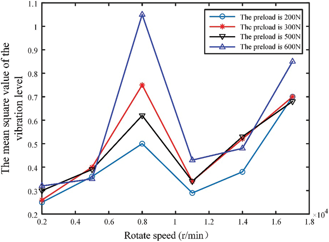
Figure 5: Vibration level under different rotating speeds and preload
Conversely, when the influence of the axial preload is insignificant, increasing the preload is essential to ensure the stiffness of the bearing and the overall system. Bearing noise is generated by mechanical waves that cause air vibrations due to the vibration of the bearings. Even if individual bearing components are perfectly machined, the relative movements between the inner and outer rings, cages, and balls cannot be eliminated entirely during operation.
In general, the axial preload induced a slight change in the bearing noise, as listed in Table 2. Applying an axial preload to the bearing increases its stiffness, thereby significantly influencing the bearing and entire system [31]. Optimal axial preload applications can effectively mitigate issues such as acoustic noise.

The key advantage of multisensor fusion technology is its ability to enhance the accuracy and perception capabilities of sensing systems. By combining the observation information acquired from multiple sensors at different levels and perspectives, we can extract more valuable insights. This, in turn, improves the decision-making reliability, confidence, and environmental adaptability of the system. Through applying multisensor fusion, we gained a deeper understanding of how the bearing preload is influenced by multiple factors, allowing us to determine the optimal preload value comprehensively.
3 Controlled Preload Test Bench Design
Preload is the most important part of an experiment, and the accuracy of the data must be guaranteed. This test bench was designed as a closed test bench that can be adjusted by a servomotor, and the test used a multisensor fusion method to measure the controllable preload. In the experiment, the sensor and FPGA data interacted with each other so that the test could obtain higher precision, and the data could also be fed back to the host computer in real time.
An appropriate preload is important for system operation and bearing life, among other factors. Determining the optimal preload force involves considering various factors such as noise, vibration, and temperature. This study developed a comprehensive test bench to measure and analyse all the relevant factors and provide real-time feedback. Herein, the test bench consisted of several key components, including a host computer, motor control system, torque loading unit, preload control unit, and data acquisition module (Fig. 6). AC motors, servomotors, and stepper motors were used in this setup.
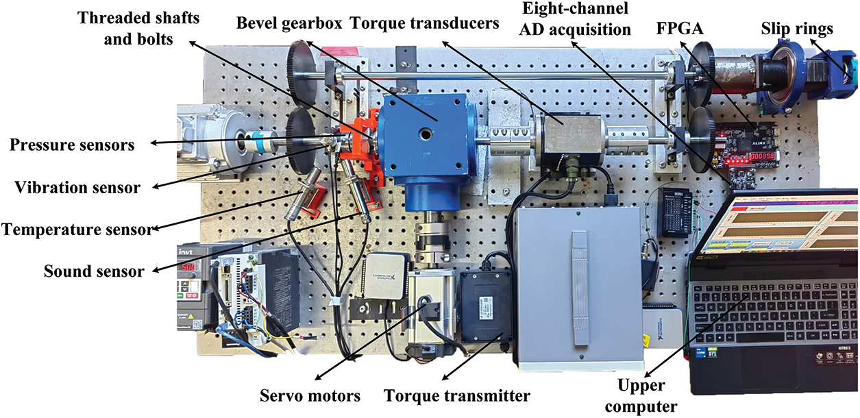
Figure 6: Test bench for optimum preload of controllable bearing
In particular, AC motors provided the drive to the system, servomotors were used to control the preload force, and stepper motors generated torque by acting on the shaft. The FPGA served as the core controller for the entire system. It facilitated the synchronisation of the eight-channel analogue-to-digital (AD) conversion, enabling the conversion of changing analogue voltages from specified IO ports into numerical values. This process was an integral part of the signal sampling procedure. Using this systematic configuration and employing advanced technologies, the experiment ensured accurate measurement, analysis, and control of the preload, thereby enhancing our understanding of its impact on the system performance, bearing life, and other relevant aspects.
A closed test bench, also known as a power flow closed test bench is primarily used to evaluate the performance of mechanical transmission components and their systems in an enclosed environment. Its purpose is to determine the service life of each component, assess the work efficiency, and identify the impact of factors such as materials and loads. A closed test bench offers several advantages, including a simple structure and low cost, low energy consumption, strong economic applicability, and a wide range of applications. Closed test benches can be classified based on the closed methods employed, with the main types being electrically closed, hydraulically closed, and mechanically closed. A mechanically closed method was adopted for the test bench.
The test bench shown in Fig. 7 consists of two pairs of gears. These gears were meshed together with z1, z4, z2, and z3, which were connected by shafts. The loading device was positioned on the right side of gear z4, and the torque was transmitted through gap matching between the gears, shafts, and system. Shafts 1 and 2 in the entire system, spanning from z3 to z4, received the torque retained within the system. This torque represents the load added to the system, known as the closed torque. Different closed powers were obtained by adjusting the torque and rotational speed.

Figure 7: Closed system structure
The loading device in this test bench primarily consisted of a loading gear and a motor. The gear and shaft were clearance-matched, facilitating the convenient adjustment of the applied load on the shaft. Although the system is closed, when functioning, it will cause unequal energy loss due to friction and other factors. These losses will be compensated by the drive device; therefore, the power output by the drive device is only used to make the system run, which can also compensate for the power lost by friction in the system. This part of the power is generally small; hence, the energy output required by the drive device is not significant.
3.3 Dynamic Torque Loading Design
The dynamic torque transducer employed in this test bench enabled torque measurement in both the positive and negative directions through noncontact power supply and signal output methods. The test bench incorporated a designed dynamic torque loading system, where the torque served as a control variable owing to its influence on the optimal preload. Before the commencement of the test bench system operation, the loading system applied torque to the entire system. Through closed transmission within the entire system, the power-flow direction was determined by the rotation direction of the loading and driving devices. A significant portion of the power of the active gear was transmitted to the driven gear drive system, which generated a force that sequentially propagated from the active gear to the driven gear. Eventually, z3 and z4 produced torques of the same magnitude but in opposite directions owing to their opposing rotation directions. Consequently, the system rotated under the influence of this torque. This validates the operation of the entire system, including the presence of torque, impact of preload, and other factors.
Various closed powers were achieved on the test bench by manipulating the torque and rotational speed. The loading device primarily consisted of a loading gear and motor. The gear and shaft were designed with appropriate clearance, facilitating the convenient adjustment of the applied load on the shaft.
A stepper motor was employed to control the system and apply torque to facilitate the experimentation. This allows for the real-time adjustment of the torque within the system. Furthermore, the motor was equipped with a self-locking mechanism that ensured the torque remained locked and did not change during operation. This feature enhanced the stability and consistency of the system during testing.
On this test bench, the application of a preload was achieved indirectly by rotating a threaded nut driven by a bevel gearbox. The motor drove the bevel gearbox to rotate at a specific angle via coupling. Within the bevel gearbox, the bevel gears meshed with each other, causing the output shaft to rotate. The front side of the output shaft was threaded and equipped with a suitably sized nut. This nut was secured on both sides by ferrules, preventing it from rotating circumferentially (Fig. 8).

Figure 8: Three-dimensional diagram of the test bench and explosion diagram of preload
When the test shaft was rotated, the threaded portion at the front of the shaft caused the fixed nut to move horizontally along the threaded shaft. This horizontal movement of the nut occurred in the direction of the measured bearing. Consequently, the nut transmitted a force to the bearing through the top sleeve and pressure sensor. The current preload was accurately determined by collecting the force received by the pressure sensor.
This method of obtaining preload offered both stability and controllability. The threaded shaft remained fixed owing to motor fixation and did not rotate during the measurement process. After the nut moved forward, it remained fixed by a ferrule. Consequently, both the circumference of the nut and threaded shaft remain fixed, ensuring that the position of the nut and magnitude of the preload remain constant.
3.5 Test Bench Measurement and Control System Design
The measurement and control systems of the controllable bearing optimal preload test bench were divided into hardware and software designs. The hardware design primarily included the core controller FPGA, various sensors, and a host computer. This part primarily realised a controllable preload and data acquisition and transmission of each sensor. The software design displayed the measured value and optimal preload of each sensor online.
The hardware design of the measurement and control system primarily comprised a core controller field-programmable gate array (FPGA), pressure sensor, temperature rise sensor, noise sensor, vibration acceleration sensor, torque speed sensor, host computer, motor, and controller. A multisensor fusion architecture with two inputs and three outputs was constructed to determine the optimal preload for the best bearing performance (Fig. 9).
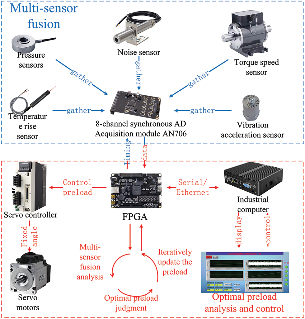
Figure 9: Hardware architecture of measurement and control system
The hardware of the measurement and control system can be divided into two modules: the multisensor fusion module and optimal preload analysis and control module. The multisensor fusion module was primarily based on the AN706 eight-channel synchronous AD acquisition module. This module enabled the simultaneous collection of measurements from five different sensors.
The sampling frequency of the system can reach 200 MHz with parallel control of a high-precision, low-timing FPGA. This allowed for high-speed and low-error voltage acquisition, ensuring synchronisation of the data from all five sensors. The architecture of the multisensor fusion module incorporated the pressure and torque speed sensors as two inputs, whereas the temperature rise, noise, and vibration acceleration sensors served as three outputs.
All five sensors, either through their own voltage output or conversion by the corresponding transmitter, produced a voltage signal within the 0–5 V range. Therefore, multichannel AD acquisition was highly suitable for this setup. Among these sensors, the pressure, temperature rise, noise, and torque speed sensors all provided a voltage output within the 0–5 V range according to their respective measurement ranges. The voltage output of the vibration accelerometer increased with the vibration intensity but did not exceed 5 V. The data collected from the five sensors and FPGA interacted using an SPI bus, ensuring synchronisation and efficient data transfer.
In the optimal preload analysis and control module, the field-programmable gate array (FPGA) served as the core controller responsible for data collection and real-time monitoring of preload values using pressure sensors. This allowed the determination of the current preload force through multisensor fusion. If the current preload force was not optimal, an iterative process was initiated to update the preload force gradually.
The preload force was controlled by the angle of rotation of the servomotor. A larger angle corresponded to a greater preload force. The required angle of the servomotor was determined by the number of pulses generated by the servo controller. By writing a Verilog program in advance, the FPGA incrementally increased the pulse output of the corresponding pin to control the iterative update of the preload force. By continuously adjusting the pulse output, the FPGA enabled the servomotor to rotate incrementally, thereby increasing the preload force in small increments. This process facilitated the collection of new data and the subsequent evaluation of the optimal preload force. An iterative update of the preload value ensured that the system could dynamically adjust and maintain optimal preload conditions.
4 Experimental Setup and Result Analysis
Feature extraction was performed after data preprocessing, which is the process of converting the original signal into a meaningful feature vector. This process eliminated unnecessary noise and interference as well as performed data normalisation and standardisation, enabling more effective learning and classification by neural networks.
The vibration signal was captured using a vibration acceleration sensor that encompassed time, frequency, and time-frequency domain characteristics. The time-domain feature is a fundamental characteristic that provides insight into the overall trend and distribution of the signal. The frequency-domain characteristics reveal the frequency and energy distributions of the signal. Time-frequency domain characteristics depict both the time and frequency domain features of the signal. In this study, the time-frequency domain analysis method was employed to extract features such as the frequency range, amplitude, and time range, as depicted in Fig. 10. It is evident that the application of preload results in a significant increase in vibration levels.

Figure 10: Vibration signals and frequency domain signals under no preload and 100 N preload
The noise signal was captured using a noise sensor microphone, encompassing various characteristics, such as the sound pressure level, frequency characteristics, spectral analysis, and time-domain characteristics. The sound pressure level serves as a fundamental feature that reflects noise intensity. The frequency characteristics depict the energy distributions of the different frequency components within the noise signal. Spectral analysis enables the acquisition of power spectral density and frequency distribution of noisy signals. The time-domain characteristics reveal the waveform and statistical features of the noisy signal.
Herein, a combination of frequency- and time-domain analyses was employed for the feature extraction of noise signals. Particularly, the time-domain characteristics of the noise signal were obtained through a time-domain analysis. Subsequently, a spectral analysis was conducted to obtain the frequency-domain characteristics of the noise signal. Fig. 11 illustrates the noise signal and its frequency-domain representation under no preload force and with a preload force of 100 N. The application of a 100 N preload force significantly reduced the noise level. Unlike vibration and noise signals, temperature rise signals primarily reflect the operational and thermal equilibrium states of rolling bearings. The characteristics of the temperature rise signals include the steady-state temperature, temperature change rate, and temperature gradient. The feature extraction of temperature rise signals typically involves a combination of traditional statistical methods and machine learning techniques.

Figure 11: Noise signal and frequency domain signal under no preload and 100 N preload
This study employed statistical functions for feature extraction of the temperature rise signals. The statistical features of the temperature increase signal were extracted, and Fig. 12 shows the temperature increase signal under no preload force and with a preload force of 100 N. When no preload force was present, the change rate, mean, maximum, and minimum values were 0.005, 21.935, 21.301, and 21.612, respectively. Conversely, when a preload force of 100 N was applied, the change rate, mean, maximum value, and minimum value were 0.003, 22.683, 22.296, and 22.462, respectively. Therefore, applying the preload force significantly inhibited the rate of change in the temperature increase.
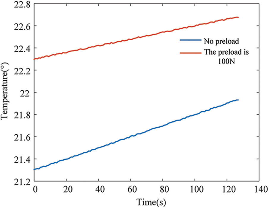
Figure 12: Temperature rise signal under no preload and 100 N preload
All evidence does not have the same confidence level in the fusion of information and decision-making processes. Therefore, weighted evidence can be obtained by introducing the credibility of evidence, weighted by the credibility of evidence, weighted by each evidence frame, and a weighted sum to obtain the weighted evidence, thereby solving this problem. The calculation formula is as follows:
where
The comprehensive rule of the D–S evidence theory is used to integrate the three sets of weighted evidence, and the formula is:
when dealing with conflicting information in evidence synthesis using synthetic rules, the Dempster–Shafer (D–S) evidence theory can introduce paradoxes and result in fusion failure. To address the challenge of conflicting evidence, evidence fusion often involves assigning different weights to individual sensors. However, determining the appropriate weights for each sensor can be a complex task, requiring substantial prior knowledge or experience.
Therefore, this study proposes an enhanced multisensor fusion weighting algorithm to significantly enhance the accuracy of fault diagnosis. Using this algorithm, the fusion process can effectively handle evidence conflicts and improve the reliability of diagnostic outcomes.
4.3 Improved Multisensor Fusion Weighting Algorithm
In practical scenarios, different sensors exhibit varying levels of reliability, thereby influencing confidence in evidence synthesis. For an information fusion system comprising n sensors, the weight assigned to each sensor can be determined through reliability testing and simulation analyses. These weights are denoted as
The prior weight represents the relative reliability of each sensor based on the aforementioned analyses. However, the actual working environment introduces uncertainties, necessitating the calculation of evidence similarity to obtain real-time sensor reliability, referred to as the posterior weight. A novel method for evidence synthesis can be derived by considering both prior and posterior weights [32].
By incorporating prior weights that reflect the initial reliability assessment and posterior weights obtained through evidence similarity calculations, this new methodology facilitates more accurate and adaptive evidence synthesis in dynamic environments.
Let there be n incompatible pieces of evidence, where the basic trust distribution functions of any two pieces of evidence
where
In the above formula,
Combining Eqs. (20) and (21) yields
Define the body of evidence
Each evidence available supports the
Normalization is available as:
Eq. (26) reflects the confidence of evidence
Then,
Corresponding signal processing methods were employed to extract the features from these sensors. To minimise the errors, the characteristic signals from each sensor were averaged. Subsequently, a multisensor-weighted fusion approach was employed using the aforementioned algorithm. This fusion technique measured the mean, variance, and standard deviation of the weighted signal to determine the optimal preload force required to achieve the maximum bearing performance (Fig. 13). The smaller the parameters obtained after weighted fusion, the closer it is proved to be to the optimal preload of the bearing. We can get a more correct bearing preload through experiments. Compared with the traditional method of bearing preload determination, the method used in this paper uses multiple sensors and signals, and the results obtained are more stable and reliable, and the robustness is stronger, and will not have a serious impact on the whole system due to problems caused by a certain set of data. At the same time, sensors have different response capabilities to target information, and may give incomplete or indeterminate information. In order to improve the reliability and credibility of the information fusion results of multi-sensor systems, this paper obtains the posteriori weights of the evidence by calculating the similarity matrix between the evidences, and combines the prior weights pre-assigned according to the inherent reliability of the sensors to obtain the composite weights of the evidence body, and then weights the weighted average of the evidence, and finally uses the D-S synthesis formula to fuse the evidence.

Figure 13: Sensor weighted fusion
In the controllable preload test bench developed in this study, the temperature increase was monitored within a range of 25°C through orthogonal experiments involving various speeds and torques. Three sets of signals, namely, noise, vibration, and temperature rise, were collected from multiple sensors. These three sets of signals will reflect the changes of parameters such as preload torque when the system is working, and these three sets of data will be analyzed, and the signals before and after the initial conditions of the system are changed, and they will be fused. From the results shown in Fig. 14, it can be observed that, under low-speed operating conditions for rolling bearings, applying a large torque is favourable for enhancing the bearing stiffness. Conversely, when operating at high speeds, a smaller torque is more suitable for reducing the performance degradation caused by a temperature increase. By applying a certain torque, the preload force was reduced to a certain extent.

Figure 14: Optimum preload at different speeds and torques
Compared with the latest articles in the field of data fusion [33,34], Pan uses an improved stochastic weighting algorithm to effectively deal with rolling bearing fault diagnosis, but its use has certain limitations, due to the large difference in vibration frequency between different bearing faults, its effectiveness will be limited when dealing with mixed faults or other faults with small frequency differences. Moreover, the stochastic weighting algorithm itself still has problems such as high requirements for samples and parameters, easy to be disturbed by abnormal data, and unable to deal with non-stationary environments, which causes difficulties in application. The method used in this paper is more flexible, adaptable and robust, which can better deal with uncertainty and conflicting information, and provide more accurate and reliable fusion results. It also better handles high-conflict evidence and converges faster. The results obtained in this paper are shown in Fig. 14 and have been verified to be more than 99% accurate. In summary, the multi-sensor fusion method proposed in this paper has certain advantages over the traditional method, and can obtain more stable and accurate results.
Fitting a neural network is the process of adjusting the parameters of a neural network model so that it can learn from the input data and approximate the desired output [35]. Neural networks are composed of multiple levels of nonlinear units that are capable of learning and expressing complex nonlinear patterns, so they can fit a variety of complex data patterns well. The fitting ability of a neural network allows it to be used to predict data, classify and identify. The accuracy of the results obtained in this paper is determined by fitting the best preload obtained in this paper.
The neural network fitting process involves the iterative optimisation of the activation function coefficients for each neuron, creating a progressive improvement in performance. In this study, a Simple Neural Network (SNN) model was used because it offers optimal performance with a straightforward structure. The SNN model comprised a hidden layer containing multiple neurones and an output layer consisting of a single neuron. The topology of the complete SNN model is shown in Fig. 15.
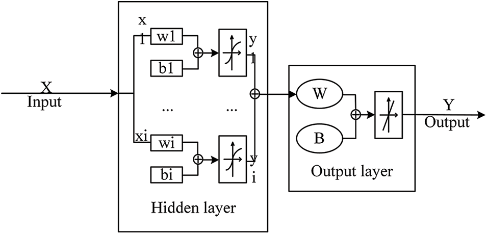
Figure 15: Neural network topology
For each neuron in the hidden layer of the SNN model, the output can be expressed as:
In the SNN model, the weights and biases of each neuron are denoted as
According to the topology of the SNN model, we can obtain the output of the SNN model as:
The weights and biases of the output layer are denoted W and B, respectively. The output signal yi from each neuron in the hidden layer is passed to the output layer. Through a linear transformation, the SNN model produced an output value of Y. The activation function of the output layer was linear. During training, mean squared error (MSE) determined the convergence of the function. The minimum MSE corresponded to the optimal curve fit of the dataset. To achieve this, the weights and biases of the neurones in the hidden and output layers were adjusted. The mean squared error (MSE) between the output value Y of the SNN model and test data was compared, and iterative training using the error descent method was performed along the gradient direction. The procedure was designed to determine the model parameters that resulted in minimal MSE.
The optimal preload data obtained from the measurements were selected for fitting using deep-learning techniques. The fitting results are shown in Fig. 16, which illustrates the regression between the measured and output data of the SNN model. An approximately linear relationship exists between the measured and output data, with an R-squared value of 0.99. This high R-squared value indicates an excellent fit and substantiates the effectiveness of the SNN model.

Figure 16: Fit regression
This study proposes a novel model for controlling the preload force in bearings. This includes developing a controllable bearing preload experimental platform, measurement and control system based on an FPGA, mechanical power closed-loop design, and dynamic torque loading design. Moreover, a weighted fusion analysis method for determining the optimal preload force was introduced, which applied the D–S evidence theory in a multisensor setting. The optimal preload under different conditions obtained by algorithm fusion is shown in Fig. 14. The accuracy of the experimental results was validated by fitting the results to neural networks. The method used in this paper is widely used and has no obvious shortcomings. It can better handle high-conflict evidence, converge faster, and has distinct advantages over traditional methods, resulting in more stable and accurate results.
Acknowledgement: The authors thank the support from the Key Project of National Natural Science Foundation of China, the Open Project of State Key Laboratory of Mining Response and Disaster Prevention and Control in Deep Coal Mines, the National Key Research and Development Program of China, the Open Project of Key Laboratory of Conveyance and Equipment, the Science and Technology Research Project of Jiangxi Provincial Department of Education, the Supply and Demand Linking Employment Education Project of the Ministry of Education, Suzhou Basic Research Project, and the Open Project of State Key Laboratory for Manufacturing Systems Engineering.
Funding Statement: This research is supported by: The Key Project of National Natural Science Foundation of China (U21A20125); The Open Project of State Key Laboratory of Mining Response and Disaster Prevention and Control in Deep Coal Mines (SKLMRDPC21KF03); The National Key Research and Development Program of China (2020YFB1314203, 2020YFB1314103); The Open Project of Key Laboratory of Conveyance and Equipment (KLCE2021-05); The Science and Technology Research Project of Jiangxi Provincial Department of Education (GJJ210639); The Supply and Demand Linking Employment Education Project of the Ministry of Education (20220100621); The Open Project of State Key Laboratory for Manufacturing Systems Engineering (sklms2023009); The Suzhou Basic Research Project (SJC2023003) (Corresponding author: Yasheng Chang.).
Author Contributions: The authors confirm contribution to the paper as follows: study conception and design: Kuosheng Jiang, Yasheng Chang; data collection: Chengrui Han; analysis and interpretation of results: Kuosheng Jiang, Chengrui Han, Yasheng Chang; draft manuscript preparation: Chengrui Han, Yasheng Chang. All authors reviewed the results and approved the final version of the manuscript.
Availability of Data and Materials: The datasets used or analysed during the current study are available from the corresponding author on reasonable request.
Conflicts of Interest: The authors declare that they have no conflicts of interest to report regarding the present study.
References
1. Meng, D., Yang, S., de Jesus, A. M. P., Zhu, S. P. (2023). A novel Kriging-model-assisted reliability-based multidisciplinary design optimization strategy and its application in the offshore wind turbine tower. Renewable Energy, 203, 407–420. https://doi.org/10.1016/j.renene.2022.12.062 [Google Scholar] [CrossRef]
2. Meng, D., Yang, S., He, C., Wang, H., Lv, Z. et al. (2022). Multidisciplinary design optimization of engineering systems under uncertainty: A review. International Journal of Structural Integrity, 13(4), 565–593. https://doi.org/10.1108/IJSI-05-2022-0076 [Google Scholar] [CrossRef]
3. Meng, D., Yang, S., Lin, T., Wang, J., Yang, H. et al. (2022). RBMDO using Gaussian mixture model-based second-order mean-value saddlepoint approximation. Computer Modeling in Engineering & Sciences, 132(2), 553–568. https://doi.org/10.32604/cmes.2022.020756 [Google Scholar] [CrossRef]
4. Zhi, P., Wang, Z., Chen, B., Sheng, Z. (2022). Time-variant reliability-based multi-objective fuzzy design optimization for anti-roll torsion bar of EMU. Computer Modeling in Engineering & Sciences, 131(2), 1001–1022. https://doi.org/10.32604/cmes.2022.019835 [Google Scholar] [CrossRef]
5. Tian, Z., Zhi, P., Guan, Y., He, X. (2023). An active learning Kriging-based multipoint sampling strategy for structural reliability analysis. Quality and Reliability Engineering International, 40(1), 524–549. https://doi.org/10.1002/qre.3403 [Google Scholar] [CrossRef]
6. Xie, J., Tian, Z., Zhi, P., Zhao, Y. (2023). Reliability analysis method of coupling optimal importance sampling density and multi-fidelity Kriging model. Eksploatacja i Niezawodność–Maintenance and Reliability, 25(2), 161893. https://doi.org/10.17531/ein/161893 [Google Scholar] [CrossRef]
7. Qin, F., Chen, Y., Sun, X., Wang, Y., Dai, G. et al. (2019). An adjustable magnetic preloading and stepping controlled piezoelectric traveling-wave ultrasonic micromotor. Journal of Microelectromechanical Systems, 28(2), 264–270. https://doi.org/10.1109/JMEMS.2018.2889864 [Google Scholar] [CrossRef]
8. Tian, Z., Zhi, P., Guan, Y., Feng, J., Zhao, Y. (2023). An effective single loop Kriging surrogate method combing sequential stratified sampling for structural time-dependent reliability analysis. Structures, 53, 1215–1224. https://doi.org/10.1016/j.istruc.2023.05.022 [Google Scholar] [CrossRef]
9. Meng, D., Yang, S., Zhang, Y., Zhu, S. (2019). Structural reliability analysis and uncertainties-based collaborative design and optimization of turbine blades using surrogate model. Fatigue & Fracture of Engineering Materials & Structures, 42(6), 1219–1227. https://doi.org/10.1111/ffe.12906 [Google Scholar] [CrossRef]
10. Tian, Y., Zhao, X., Shi, Q. (2021). Effect of preload force on the nonlinear dynamic characteristics of bolted structure. 2021 3rd International Academic Exchange Conference on Science and Technology Innovation (IAECST), pp. 935–939. Guangzhou, China.https://doi.org/10.1109/IAECST54258.2021.9695634 [Google Scholar] [CrossRef]
11. Xu, T., Xu, G., Zhang, Q., Hua, C., Tan, H. et al. (2013). A preload analytical method for ball bearings utilising bearing skidding criterion. Tribology International, 67, 44–50. https://doi.org/10.1016/j.triboint.2013.06.017 [Google Scholar] [CrossRef]
12. Choi, C. H., Cha, N. H., Lee, C. M. (2013). A fundamental study on the development of a variable preload device using toggle joint mechanism. Journal of the Korean Society of Precision Engineering, 30(3), 260–265. https://doi.org/10.7736/KSPE.2013.30.3.260 [Google Scholar] [CrossRef]
13. Soares Dos Santos, M. P., Ferreira, J. A. F. (2014). Novel intelligent real-time position tracking system using FPGA and fuzzy logic. ISA Transactions, 53(2), 402–414. https://doi.org/10.1016/j.isatra.2013.09.003 [Google Scholar] [PubMed] [CrossRef]
14. Wang, Z., Zhao, D., Guan, Y. (2023). Flexible-constrained time-variant hybrid reliability-based design optimization. Structural and Multidisciplinary Optimization, 66(4), 66–89. https://doi.org/10.1007/s00158-023-03550-8 [Google Scholar] [CrossRef]
15. Chen, Y., Schmidt, S., Heyns, P. S., Zuo, M. J. (2021). A time series model-based method for gear tooth crack detection and severity assessment under random speed variation. Mechanical Systems and Signal Processing, 156, 107605. https://doi.org/10.1016/j.ymssp.2020.107605 [Google Scholar] [CrossRef]
16. Zhang, Y., Liu, Y., Yang, M., Feng, X., Zhu, Q. et al. (2023). Research on the service condition monitoring method of rolling bearings based on isomorphic data fusion. Lubricants, 11(10), 429. https://doi.org/10.3390/lubricants11100429 [Google Scholar] [CrossRef]
17. Lv, M., Xu, W., Chen, T. (2019). A hybrid deep convolutional and recurrent neural network for complex activity recognition using multimodal sensors. Neurocomputing, 362, 33–40. https://doi.org/10.1016/j.neucom.2019.06.051 [Google Scholar] [CrossRef]
18. Lee, E. H., Musicki, D., Song, T. L. (2014). Multi-sensor distributed fusion based on integrated probabilistic data association. 17th International Conference on Information Fusion (FUSION), pp. 1–7. Salamanca, Spain. [Google Scholar]
19. Yu, Y., Shi, P., Tian, J., Xu, X., Hua, C. (2023). Rolling mill health states diagnosing method based on multi-sensor information fusion and improved DBNs under limited datasets. ISA Transactions, 134, 529–547. https://doi.org/10.1016/j.isatra.2022.08.002 [Google Scholar] [PubMed] [CrossRef]
20. Peng, H., Cao, X. (2010). Research conflict problems of D-S evidence and its application in multi-sensor information fusion technology. 2010 IEEE International Conference on Information Theory and Information Security, pp. 747–750. Beijing, China. https://doi.org/10.1109/ICITIS.2010.5689673 [Google Scholar] [CrossRef]
21. Zhang, K., Wang, Z., Guo, L., Peng, Y., Zheng, Z. (2020). An asynchronous data fusion algorithm for target detection based on multi-sensor networks. IEEE Access, 8, 59511–59523. https://doi.org/10.1109/ACCESS.2020.2982682 [Google Scholar] [CrossRef]
22. Wang, M., Yan, K., Zhang, X., Zhu, Y., Hong, J. (2023). A comprehensive study on dynamic performance of ball bearing considering bearing deformations and ball-inner raceway separation. Mechanical Systems and Signal Processing, 185, 109826. https://doi.org/10.1016/j.ymssp.2022.109826 [Google Scholar] [CrossRef]
23. Zhou, X., Xu, H., Xiong, X., Wang, L. (2013). Load distribution model of deep groove ball bearing with ball off size. 2013 IEEE International Symposium on Assembly and Manufacturing (ISAM), pp. 58–63. Xi'an, China. https://doi.org/10.1109/ISAM.2013.6643488 [Google Scholar] [CrossRef]
24. Zhang, H., Cui, L. (2019). Study on dynamics properties of high speed ball bearing considering eccentric load of shaft. 2019 Prognostics and System Health Management Conference (PHM-Qingdao), pp. 1–5. Qingdao, China. https://doi.org/10.1109/PHM-Qingdao46334.2019.8943013 [Google Scholar] [CrossRef]
25. Shahidi, A., Gupta, L. A., Kovacs, A., Peroulis, D. (2013). Wireless temperature and vibration sensor for real-time bearing condition monitoring. 2013 IEEE MTT-S International Microwave Symposium Digest (MTT), pp. 1–4. Seattle, WA, USA. https://doi.org/10.1109/MWSYM.2013.6697670 [Google Scholar] [CrossRef]
26. Ma, Y., Wu, X. (2018). Discriminant sparse and collaborative preserving embedding for bearing fault diagnosis. Neurocomputing, 313, 259–270. https://doi.org/10.1016/j.neucom.2018.06.028 [Google Scholar] [CrossRef]
27. He, W., Feng, Y., Wu, S., Wang, W. (2023). Mechanical-thermal–electrical coupling modeling and temperature rise characteristic of a parallel groove clamp with improved representation of contact interactions. IEEE Transactions on Components, Packaging and Manufacturing Technology, 13(3), 356–364. https://doi.org/10.1109/TCPMT.2023.3263471 [Google Scholar] [CrossRef]
28. Wang, C. C., Yao, Y. D., Liang, K. Y., Huang, C. C., Chang, Y. C. et al. (2010). Axial vibration study of a mobile fan motor. IEEE Transactions on Magnetics, 46(6), 1397–1400. https://doi.org/10.1109/TMAG.2010.2042143 [Google Scholar] [CrossRef]
29. Yang, J., Zhao, B., Liu, B., Xia, L. (2023). The influence of friction coefficient on bolt looseness under low frequency vibration via finite element analysis. 2023 5th Asia Energy and Electrical Engineering Symposium (AEEES), pp. 512–515. Chengdu, China. https://doi.org/10.1109/AEEES56888.2023.10114113 [Google Scholar] [CrossRef]
30. Sung, S. J., Jang, G. H., Jang, J. W., Song, J. Y., Lee, H. J. (2013). Vibration and noise in a HDD spindle motor arising from the axial UMF ripple. IEEE Transactions on Magnetics, 49(6), 2489–2494. https://doi.org/10.1109/TMAG.2013.2245318 [Google Scholar] [CrossRef]
31. Wang, S., Zhang, N., Wang, S., Zhu, T., Duan, N. et al. (2018). Comparative analysis of mechanical properties of power transformer windings in short-circuit fault under different preload loading modes. 2018 21st International Conference on Electrical Machines and Systems (ICEMS), pp. 1757–1760. Jeju, Korea (South). https://doi.org/10.23919/ICEMS.2018.8549410 [Google Scholar] [CrossRef]
32. Li, J., Suo, B., Li, S. (2011). Improved multi-sensor weighted fusion method based om evidence theory. Computer Measurement & Control, 19(10), pp. 2592–2595. https://doi.org/10.16526/j.cnki.11-4762/tp.2011.10.080 [Google Scholar] [CrossRef]
33. Pan, Z., Zhang, Z., Meng, Z., Wang, Y. (2023). A novel fault classification feature extraction method for rolling bearing based on multi-sensor fusion technology and EB-1D-TP encoding algorithm. ISA Transactions, 142, 427–444. https://doi.org/10.1016/j.isatra.2023.07.015 [Google Scholar] [PubMed] [CrossRef]
34. Pan, Z., Guan, Y., Sun, D., Fan, H., Lin, Z. et al. (2023). Fast fault diagnosis method of rolling bearings based on compression features in multi-sensor redundant observation environment. Applied Acoustics, 211, 109573. https://doi.org/10.1016/j.apacoust.2023.109573 [Google Scholar] [CrossRef]
35. Chang, Y., Wang, W. (2021). A deep learning-based weld defect classification method using radiographic images with a cylindrical projection. IEEE Transactions on Instrumentation and Measurement, 70, 1–11. https://doi.org/10.1109/TIM.2021.3124053 [Google Scholar] [CrossRef]
Cite This Article
 Copyright © 2024 The Author(s). Published by Tech Science Press.
This work is licensed under a Creative Commons Attribution 4.0 International License , which permits unrestricted use, distribution, and reproduction in any medium, provided the original work is properly cited.
 Downloads
 Citation Tools