
 Submit a Paper
 Propose a Special lssue
 Open Access
ARTICLE

A Simplified Method for the Stress Analysis of Underground Transfer Structures Crossing Multiple Subway Tunnels
1 College of Civil Engineering, Tongji University, Shanghai, 200092, China
2 China Construction 4th Engineering Bureau 6th Corp., Ltd., Shanghai, 201199, China
3 Department of Civil and Architecture Engineering, Hubei Polytechnic University, Huangshi, 435003, China
* Corresponding Author: Dajiang Geng. Email:
Computer Modeling in Engineering & Sciences 2024, 139(3), 2893-2915. https://doi.org/10.32604/cmes.2024.046931
Received 19 October 2023; Accepted 28 December 2023; Issue published 11 March 2024
 View Full Text
 Download PDF
Abstract
According to the design specifications, the construction of extended piles involves traversing the tunnel’s upper region and extending to the underlying rock layer. To address this challenge, a subterranean transfer structure spanning multiple subway tunnels was proposed. Deliberating on the function of piles in the transfer structure as springs with axial and bending stiffness, and taking into account the force balance and deformation coordination conditions of beams and plates within the transfer structure, we established a simplified mechanical model that incorporates soil stratification by combining it with the Winkler elastic foundation beam model. The resolved established simplified mechanical model employed finite difference technology and the Newton-Simpson method, elucidating the mechanical mechanism of the transfer structure. The research findings suggest that the load carried by the upper structural columns can be transferred to the pile foundation beneath the beams through the transfer structure, subsequently reaching the deep soil layer and ensuring minimal impact on adjacent tunnels. The established simplified analysis method can be used for stress analysis of the transfer structure, concurrently considering soil stratification, pile foundation behavior, and plate action. The pile length, pile section size, and beam section size within the transfer structure should account for the characteristics of the upper load, ensuring an even distribution of the beam bending moment.Keywords
Given the ongoing evolution of urban construction, the practice of conducting tunnel construction in proximity to existing pile foundations and pile foundation construction near operational tunnels has become commonplace. Scholars worldwide have extensively investigated the reciprocal influence between tunnels and pile foundations [1–3]. The examination of tunnel excavation effects on nearby existing pile foundations primarily employs methods such as theoretical analysis, analysis of on-site monitoring data [4], finite element method (FEM) calculations, and physical model testing [5–9]. The theoretical analysis method predominantly employs a two-stage analysis approach. In the initial stage, column hole expansion theory, ball hole expansion theory [6], and plane hole contraction theory [9,10] were employed to deduce the displacement field of the surrounding soil resulting from tunnel excavation. In the subsequent stage, the pile foundation was treated as Winkler elastic foundation beam [11], Pasternak elastic foundation beam [12], and Kerr elastic foundation beam [9], applying the displacement field obtained in the first stage to the elastic foundation beam enables the determination of the impact of tunnel excavation on nearby existing pile foundations. In the case of U-shaped tunnels, the conformal mapping method can project them onto the unit circle, and then an analytical solution for the impact of U-shaped tunnel excavation on adjacent pile foundations can be derived by integrating the complex function method and load transfer method [13]. The analytical equation for the failure surface of the upper pile foundation’s end-bearing layer resulting from tunnel excavation can be derived using the variational principle [14]. Given the convenience and cost-effectiveness of the finite element method, numerous studies on the impacts of tunnel excavation on nearby existing pile foundations were conducted through this method [15,16]. This encompassed an exploration of various aspects, mainly including the influence of diverse geometric parameters [17], the impact of different construction parameters [18,19], the distinct effects of tunnel excavation on individual pile and group piles [20,21], and the varied effects of the construction sequence of double-track tunnels on pile foundations [22,23].
Extensive research has been conducted on the influence of tunnel excavation on nearby existing pile foundations, yet there is a paucity of studies addressing the impact of pile foundation construction on adjacent existing tunnels. Wang et al. [24] introduced an analytical solution for the longitudinal settlement of tunnels resulting from the axial loading of single pile or pile groups. This was based on the extended shear displacement method and the dual parameter elastic foundation beam model, subsequently validated through finite element numerical calculations. Lueprasert et al. [25] explored the impact of axial loading on nearby existing tunnels through finite element numerical calculation methods. Liu et al. [26] employed the tunnel project of Wuxi Metro Line 2 in China as the background. They utilized finite element numerical calculation methods and integrated on-site measured data to elucidate the impact mechanism of static pile pressing on the existing subway tunnel structure. Gao et al. [27] analyzed the impact of a pile foundation construction method combining Benoto bored pile and conventional circulating mud construction technology on adjacent tunnels. They employed on-site monitoring methods, with the Nanjing subway tunnel serving as the study background.
The use of a one-column-one pile foundation finds diverse applications in engineering. However, in certain cases, the design specifications may necessitate the installation of long pile foundations directly above shallow-buried tunnels. During practical construction, it becomes necessary for the pile foundation to traverse the tunnel’s upper portion and reach the rock layer beneath, a practice that is evidently impractical. Addressing the challenge of transferring comparable column loads to deep soil without causing a substantial impact on nearby tunnels is a pressing concern in engineering. Grounded in the first phase project of the Hangzhou Convention and Exhibition Center, this paper introduces an underground transfer structure spanning multiple subway tunnels. Employing theoretical analysis methods, we established a simplified mechanical model for the transfer structure that can concurrently account for soil stratification, pile foundation behavior, and plate action. The finite difference method and Newton-Simpson method were employed to solve the established mechanical model, elucidating the mechanical mechanism of the transfer structure. The key innovations are as follows: ① Proposal of an underground transfer structure spanning multiple subway tunnels, facilitating the transfer of loads from upper structural columns to the pile foundation beneath the beams through the transfer structure, thus transmitting to the deep soil and ensuring minimal impact on adjacent tunnels. ② Provision of a simplified analysis method for the force mechanism of the transfer structure by integrating theoretical analysis methods. The established simplified analysis method in this paper is applicable for stress analysis of transfer structures, considering soil stratification, pile foundation behavior, and plate action simultaneously. ③ The practical application of transfer structures and the corresponding simplified analysis methods in engineering has substantiated the effectiveness of these simplified structures and analysis approaches.
2 Proposal of Transfer Structure
2.1 Project Introduction and Difficulties
The upper main structure of the first phase project of the Hangzhou Convention and Exhibition Center comprises a steel structure, wherein the central corridor aligns closely with the longitudinal direction of the tunnel. The central corridor directly overlies the tunnel, with the parallel sections spanning nearly 600 m. As illustrated in Fig. 1, the steel structure column of the central corridor descends directly above the tunnel structure. Considering the shallow buried depth of the tunnel at 14.4 m, employing a one-column-one pile foundation in a pile length of 75 m. Consequently, it is unfeasible to conduct pile foundation construction directly beneath the column, impeding the direct transmission of the upper load carried by the column into the foundation.
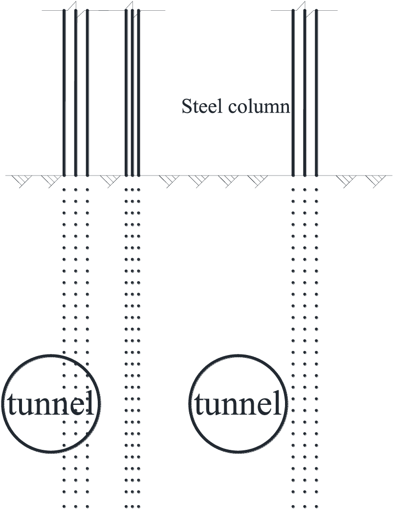
Figure 1: The relative position relationship between steel structure columns and tunnels
2.2 Proposal of Transfer Structure
To seamlessly transfer the load of the steel structure column within the central corridor to the foundation, mitigating any substantial impact on adjacent tunnels, an underground transfer structure spanning multiple subway tunnels was suggested, as depicted in Fig. 2. This approach ensures that the load carried by the upper structural columns is effectively transferred to the pile foundation beneath the beams through the transfer structure, subsequently reaching to the deep soil and minimizing any adverse effects on nearby tunnels.
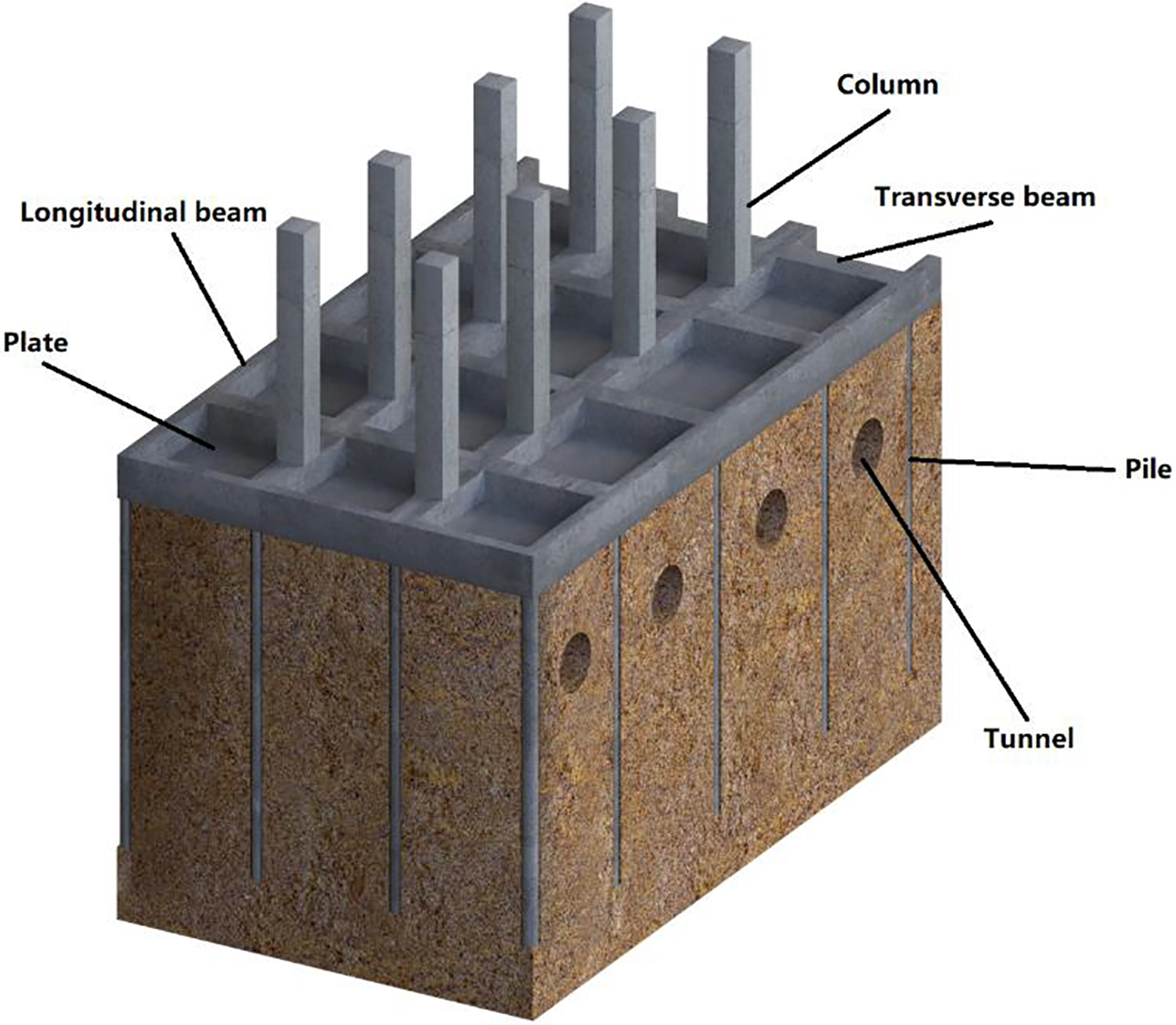
Figure 2: Transfer structure 3D diagram
3 Simplified Mechanical Model of Transfer Structure
3.1 Clarification of the Transmission System
As illustrated in Fig. 3, the transfer sequence of the transfer structure for the distributed load and self-weight of the bearing plate unfolds as follows: a portion of the load is conveyed to the longitudinal and transverse beams through the bearing plate, while another portion is transferred to the soil beneath the plate. Both the longitudinal and transverse beams bear not only the load transmitted by the bearing plate but also the vertical load transmitted from the upper structural column. Consequently, the load carried by these beams is distributed, with a segment transmitted to the soil under the beam and another segment directed to the pile foundation.
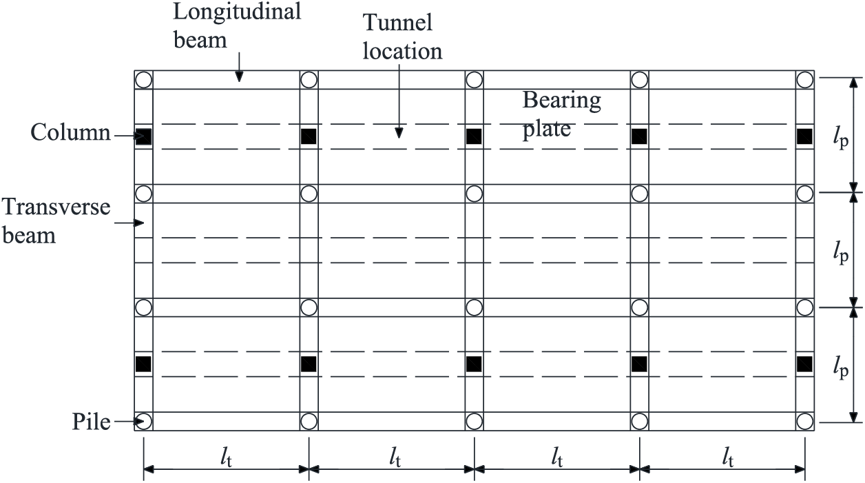
Figure 3: Transfer structure 3D diagram transfer structure plan diagram
3.2 Establishment of Mechanical Model
Given that both the distributed load carried by the bearing plate and the vertical load transmitted by the upper structural column primarily pass through the pile foundation via longitudinal and transverse beams, these beams were selected as the focal analysis components. This led to a simplified mechanical model for the transverse beams, depicted in Fig. 4a, and a simplified mechanical model for the longitudinal beams, illustrated in Fig. 4b.
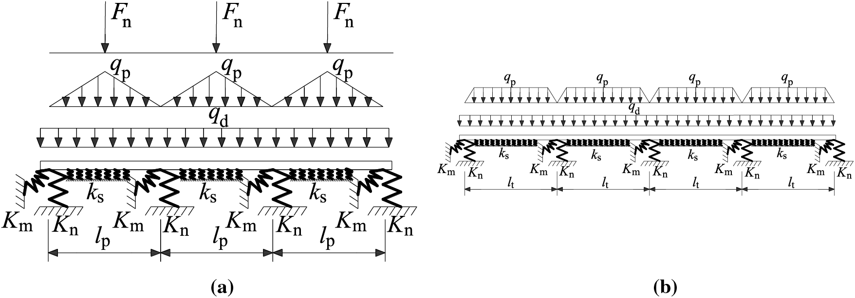
Figure 4: Simplified mechanical model: (a) Transverse beams; (b) Longitudinal beams
As illustrated in Fig. 4a, the upper load supported by the transverse beams encompasses three components:
As depicted in Fig. 4b, the upper load supported by the longitudinal beams comprises two components:
3.3 Stress Analysis of Bearing Plate
Assuming that the load on the upper section of the bearing plate is uniformly distributed, and likewise, the self-weight is uniformly distributed, the bottom reaction force provided by the soil is also uniformly distributed. The uniformly distributed surface load, denoted as
where
where
where
Upon determining the uniformly distributed surface load,
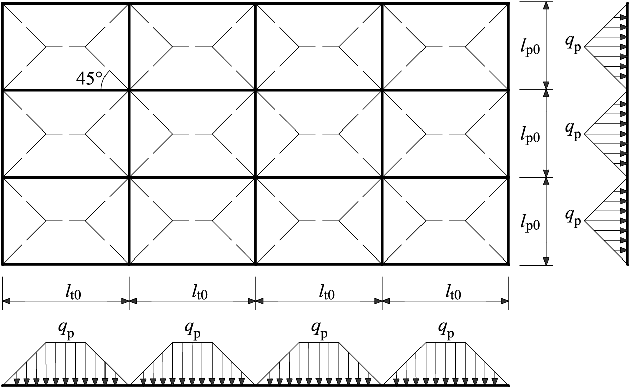
Figure 5: Load bearing plate stress model
In Fig. 4,
3.4 Calculation of Axial Stiffness
The pivotal step in determining soil reaction force at the plate’s bottom involves the calculation of the axial stiffness,
According to the finite compression layer model, the calculation formula for the settlement s of the finite compression layer foundation is [28]
where the parameters
Eq. (6a) is equivalent to
In Eq. (6a),
Let,
Similarly, the additional stress caused by the pressure
where
Substituting Eq. (6b) into Eq. (5) to obtain the settlement of the foundation directly below the center of the square:
Substituting Eq. (9) into Eq. (5) to obtain the settlement of the foundation directly below the square corner point as
After obtaining the settlement of the foundation directly below the center and corner of the square, the overall settlement of the foundation is approximately calculated according to the following equation:
The axial stiffness
3.5 Calculation of Axial Stiffness
The axial stiffness,
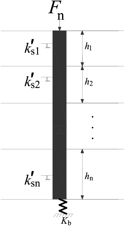
Figure 6: Pile soil vertical interaction model
where the symbol
where
3.6 Calculation of Bending Stiffness
The stress analysis methods for horizontally loaded piles can be broadly categorized into four groups: elastic analysis method [36], foundation reaction method [37], p-y curve method [38], and numerical analysis method [39]. In the engineering field, the m method in the foundation reaction method [40] is frequently employed. To maintain tractability, the m method is utilized for determining the bending stiffness,
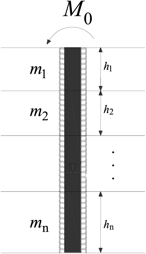
Figure 7: Pile soil lateral interaction model
where
After solving Eq. (18) based on boundary conditions, the rotation angle of the pile at the pile top position can be obtained
The boundary conditions primarily encompass those at the bottom and top of the pile, along with the coordination conditions at the soil stratification location. Assuming the bottom of the pile as a fixed end, the deflection deformation
At the interface between the i-th and i+1-th soil layers, the conditions of identical bending deformation, rotation angle, bending moment, and shear force are satisfied. Once the rotation angle
4 Solution of Simplified Mechanical Model for Transfer Structures
Upon elucidating the interaction among piles, plates, and soil, the next step involves resolving the transverse and longitudinal multi-span beam systems depicted in Fig. 3. Presently, complex beam systems are typically addressed using methods such as finite element method [41] and finite difference method [42] are mainly used to solve. Opting for the finite difference method due to its programming convenience, this method is employed to solve the beam system illustrated in Fig. 3.
The fundamental concept of the finite difference method involves substituting differential equations and boundary conditions with difference equations. This transformation turns the solution of differential equations into the solution of linear equations, significantly mitigating the complexity of the problem-solving process. In the case of the equation
4.2 Finite Difference Basic Equation
The differential equation governing deflection in the Winkler elastic foundation beam model [11] is
where the bending stiffness of the beam is denoted as
Write Eqs. (24)–(27) as matrix expressions
Partition the foundation beam into n segments, not necessarily equal in length, with node numbers 1,2,3... and n+1. The two ends of the i-th beam segment are designated as i and i+1. In practical segmentation, nodes are established at points of abrupt changes in local load, such as the three key points of triangular load and the four key points of trapezoidal load, as well as the concentrated load and various support types. Denoting the length of the i-th beam segment as Li, the segment must satisfy the differential equation presented in Eq. (28) at its center. Considering the central difference equation, the i-th beam segment adheres to the following linear equation system:
where
To address the beam system with multiple transverse and longitudinal spans depicted in Fig. 3, it is essential not only to adhere to the fundamental linear equation system Eq. (29) but also to meet the compatibility conditions at the points of concentrated force application and at the intersection nodes of longitudinal and transverse beams.
For nodes subjected to concentrated forces, it is possible to establish one node on each side of the given node. The left beam segment of the node can be computed as the left node, and the right beam segment as the right node. However, the left and right nodes must adhere to compatibility conditions, ensuring uniform deflection s, identical rotation angle, consistent bending moment, and equilibrium between shear force and concentrated force on both sides. In other words, both sides must satisfy
where
At the intersection nodes of the longitudinal and transverse beams, illustrated in Fig. 8, three primary types of nodes exist: L-shaped nodes (01, 01), T-shaped nodes (01, 02), and cross-shaped nodes (02, 02). Each node type corresponds to distinct compatibility conditions.
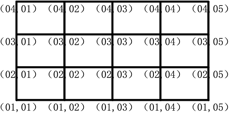
Figure 8: Intersection nodes of longitudinal and transverse beams
The L-shaped node represented by nodes (01, 01) can be deconstructed into an upper node and a right node, both exhibiting the identical deflection. The reaction force of the rotating spring support at the right node is equilibrated with the bending moment of the right node. Similarly, the reaction force of the rotating spring support at the upper node is counterbalanced by the bending moment of the upper node. Additionally, the reaction force of the vertical spring support is harmonized with the shear force and vertical concentrated force of the upper right two nodes. This configuration ensures
where the physical quantity denoted by a superscript t corresponds to the upper node. Similarly, the L-shaped nodes depicted in nodes (01, 05) adhere to
Node (04, 01) satisfies
where the physical quantity represented by a superscript b corresponds to the lower node. Node (04, 05) adheres to
For the T-shaped nodes represented in nodes (01, 02), they can be deconstructed into right, upper, and left nodes. The deflection among these three nodes is identical. The rotation angles of the right and left nodes are equal, and the bending moment of the spring support at the right and left nodes is counterbalanced by the bending moment at these respective nodes. Moreover, the reaction force of the rotating spring support at the upper nodes is equilibrated with the bending moment at the upper nodes. The reaction force of the vertical spring support is also harmonized with the shear force and the vertical concentrated force
Similarly, the T-shaped nodes shown in nodes (02, 01) satisfy
the T-shaped nodes shown in nodes (02, 05) satisfy
The cross shaped nodes illustrated in nodes (02, 02) can be deconstructed into upper, left, lower, and right nodes, adhering to the requirements of four nodes with identical deflection, upper and lower nodes sharing the same rotation angle, and the left and right nodes also possessing identical rotation angles. The reaction force of the rotating spring support at the upper and lower nodes is counterbalanced by the bending moment of the upper and lower nodes, while the reaction force of the rotating spring support at the left and right nodes is harmonized with the bending moment of the left and right nodes. The reaction force of the vertical spring support is equilibrated with the shear force at all four nodes and the vertical concentrated force
4.4 Calculation and Processing of Distributed Load on Beams
In principle, upon the completion of the beam system discretization, a comprehensive linear equation system is formulated by amalgamating Eq. (29) with compatibility conditions Eqs. (30)–(33). The resolution of this linear equation system yields the deflection, rotation angle, bending moment, and shear force at each node, facilitating the determination of internal forces and deformations in the foundation beam corresponding to the transfer structure. However, before undertaking the solution process, it is imperative to ascertain the distributed load on the beam, encompassing the beams’ self-weight and the line load transmitted from the bearing plate to the longitudinal and transverse beams. Calculating the self-weight of the beam is straightforward, with the primary focus directed toward elucidating the line load transmitted by the bearing plate to the longitudinal and transverse beams.
Substitute Eqs. (2) and (3) into Eq. (1) to derive the line load transmitted from the bearing plate to the longitudinal and transverse beams.
Considering the specific transfer structure within a particular stratum, known quantities include the surface load
By substituting Eq. (35) into Eq. (34), we can establish the relationship between the line load transmitted by the bearing plate to the longitudinal and transverse beams and the deflection at the center of the beam
By synthesizing Eqs. (29)–(33), and (36), a nonlinear equation system is derived for the deflection, rotation angle, bending moment, shear force, and line load transmitted from the bearing plate to the longitudinal and transverse beams. The Newton Simpson iteration method [41] can be applied to solve this equation, facilitating the solution for the internal forces and deformations of the foundation beams corresponding to the transfer structure.
In summary, the process for establishing and solving solution the transformational structural mechanics model is depicted in Fig. 9. Initially, the geometric and physical-mechanical parameters of the piles, longitudinal beams, transverse beams, and plates are determined for both the original and transfer structure. The formation parameters encompass the thickness of soil layers, the compression modulus for each layer of soil, the coefficient of horizontal resistance varying with depth, the vertical stiffness for each soil layer, and the spring stiffness of the pile end soil. The pile parameters mainly include diameter, length, elastic modulus, and pile end soil stiffness. The parameters of longitudinal and transverse beams comprise length, width, height, density, elastic modulus, and the concentrated force transmitted by the structural column to the beam. The plate parameters include uniformly distributed external load on the plate surface, density, thickness, and the void at the bottom of the plate. Subsequently, based on the geological parameters, Eq. (15) is employed to determine the axial stiffness
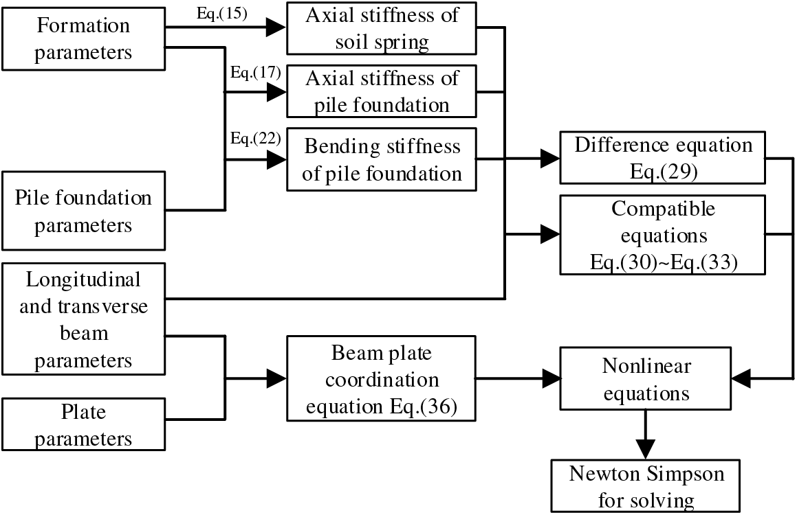
Figure 9: Mechanical model establishment and solution process
5 Application of Simplified Mechanical Model for Transfer Structure
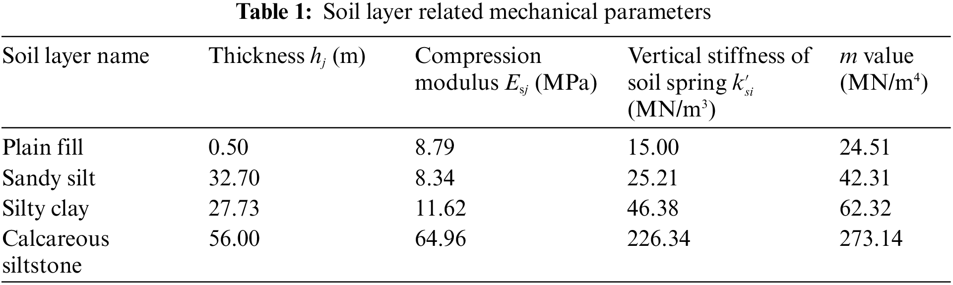
To facilitate the seamless transfer of the load from the central corridor steel structure column to the foundation while minimizing impact on the adjacent tunnel, a transfer structure, illustrated in Fig. 2, was implemented during the initial phase of the Hangzhou Convention and Exhibition Center project. Table 1 presents the pertinent parameters of the strata within which the transfer structure is situated.
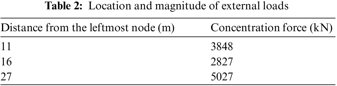
The transfer structure is horizontally segmented into 2 spans along the tunnel and vertically into 5 spans for analysis. The transverse beams boast a 16 m span and a cross-sectional profile of 1800 mm × 2000 mm, while the longitudinal beams feature a 9 m span and a cross-sectional specification of 600 mm × 1200 mm, accompanied by a plate thickness of 250 mm. Pile foundations are strategically positioned at the intersection points of longitudinal and transverse beams, each with a 0.9 m diameter. The piles on the sides extend to a length of 75 m, while those in the middle row are 78 m long. The concrete used for beams and plates is of C40 grade with elastic modulus of 3.25 × 10⁴ MPa, and for piles, C45 grade concrete is employed, also with elastic modulus of 3.25 × 10⁴ MPa. The soil stiffness at the pile end is considered as 210.00 MN/m, and the concrete density is set at 2500 kg/m3. The plate’s bottom clearance is assumed to be 0.00 mm, and a uniformly distributed external load of 2.50 kPa is applied to the board surface. The location and magnitude of concentrated loads on the beams are outlined in Table 2.
Combining the model parameters and the solution process illustrated in Fig. 9 facilitates the derivation of the internal force diagrams and deformation diagrams for the transfer structure, as depicted in Fig. 10. To validate the proposed simplified analysis method, we present corresponding results obtained through finite element analysis in Fig. 10. A clear comparison between the two methods reveals that the simplified calculation approach in this paper exhibits high accuracy and is practical for engineering calculations. The figure illustrates a maximum deflection of approximately 2.5 mm and a maximum bending moment of 7800 kN/min the middle span of the transverse beam. These extremities align closely with the positions of concentrated loads application. To optimize material strength and ensure even distribution of the bending moment along the beam length, it is advisable to consider a moderate increase in pile length at the mid-span beam position. Meanwhile, the longitudinal beam in the middle span exhibits a maximum deflection of about 2.75 mm and a maximum bending moment of 1300 kN/min. The distribution of bending moments along the beam length is notably more uniform than in the transverse beams. When designing the transfer structure, factors such as pile length, pile section size, and beam section size should be carefully considered to achieve an even distribution of bending moments. Prioritizing adjustments to the pile length is recommended for achieving uniform bending moment distribution, taking into account the practicalities of the construction process.
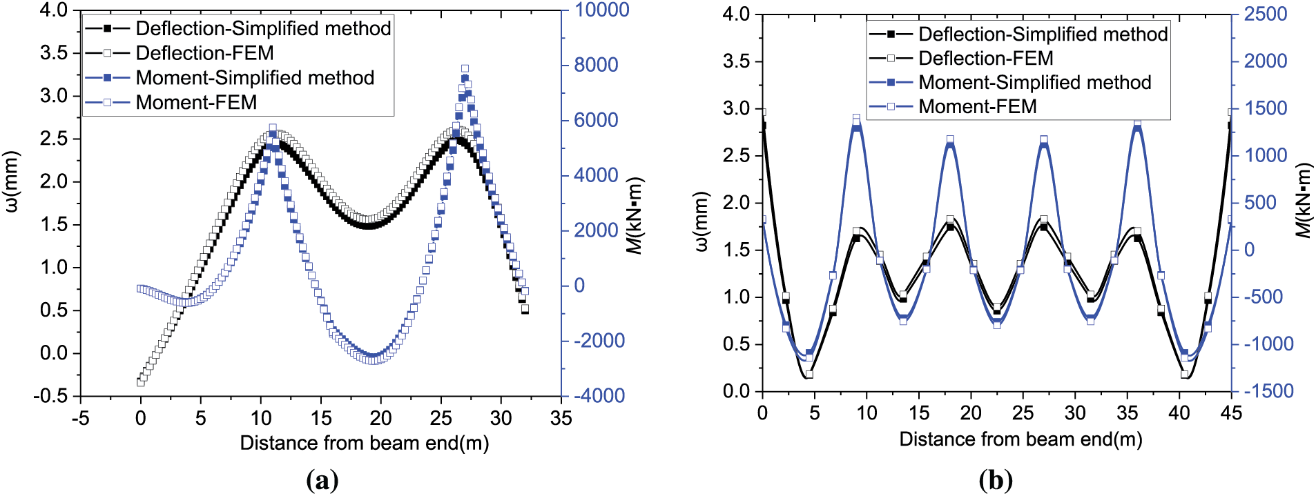
Figure 10: Transfer structure calculation results: (a) Mid span-transverse beam; (b) Mid span longitudinal beam
Section 3.2 of this paper establishes a simplified analysis method for the transfer structure, treating the beam system of longitudinal and transverse beams as a Winkler elastic foundation beam. In Figs. 4a and 4b, the pivotal aspects of Winkler elastic foundation beams involve determining the axial stiffness (ks) of the soil spring, the axial stiffness Kn of the pile foundation, and the bending stiffness Km of the pile foundation. Eq. (15) highlights the influence of soil layering and the compressive modulus of each layer on the axial stiffness of the soil spring, significantly impacting the elastic foundation beam’s solution results. Similarly, Eqs. (17) and (18) demonstrate that soil layering, mechanical properties of each soil layer, and pile foundation characteristics affect the axial and bending stiffness of pile foundations, consequently influencing the solution results of elastic foundation beams. In summary, soil stratification affects Winkler elastic foundation beams through the collective impact of soil spring axial stiffness, pile foundation axial stiffness, and pile foundation bending stiffness. Simultaneously, pile foundation characteristics affect Winkler elastic foundation beams through the combined influence of pile foundation axial stiffness and bending stiffness. Considering that the simplified analysis method in this paper is grounded in the Winkler elastic foundation beam model, its applicability should align with the scope of this model. Thus, it is primarily suited for relatively weak soil layers and not suitable for rock foundations.
The derivation process of the simplified analysis method for the transfer structure reveals that this paper approximates pile-soil interaction, beam-soil interaction, and plate-soil interaction in a linear fashion. It is evident that the derived simplified analysis method is not suitable for scenarios involving substantial deformations, such as considerable relative displacement at the pile-soil interface or extensive bending deformation of the beam. Additionally, in practical engineering applications, issues like pile foundation failure or uneven settlement may arise. To address pile foundation failure, one can simply assign zero values to the corresponding axial stiffness and bending stiffness of the pile foundation. As for uneven settlement problems of pile foundations, the simplified analysis method presented in this paper remains applicable as long as there is no significant deformation.
The transmission of load from the upper structure is channeled through columns to the longitudinal and transverse beams. Interactions occur between the longitudinal and transverse beams and the underlying soil, as well as between these beams and pile foundations. This sequential process effectively conveys the upper load to the soil and piles beneath the beams. As the soil beneath the beams bears the load, stress is disseminated to the deeper layers. Similarly, when the pile foundation assumes the load, it distributes it to the surrounding soil and the deeper layers through both the pile side and pile end. Clearly, this load transfer process imposes stringent demands on the connection nodes of longitudinal and transverse beams, as well as on the construction quality of piles. Any failure in nodes or pile foundations can alter the course of load transfer. Therefore, during the actual construction, it is imperative to rigorously ensure the quality of both node and pile foundation construction.
Given the intricate nature of soil behavior, the variability in soil properties, and the ultimate transfer of upper loads to the soil by the transfer structure, the param defining the interaction between soil and the conversion structure become pivotal in stress analysis. For enhanced safety in actual engineering design, it is advisable to prudently diminish the values of param such as Esj,
To address the engineering challenge of accommodating pile foundations traversing through tunnels, a subterranean transfer structure spanning multiple subway tunnels is proposed. This study offers a streamlined analysis approach to elucidate the force mechanism within the transfer structure by amalgamating various theoretical analysis methods. The primary conclusions are as follows:
(1) The vertical load imposed on the upper structural columns is transmitted through the transfer structure to the pile foundation beneath the beams, subsequently transferring to the deep soil. This process ensures minimal impact on adjacent tunnels.
(2) The simplified analysis method established in this study facilitates stress analysis of transfer structures, concurrently considering soil stratification, pile foundation behavior, and plate action.
(3) When designing the transfer structure, careful consideration of pile length, pile section size, and beam section size is essential to accommodate the characteristics of the upper load, ensuring an even distribution of the beam bending moment.
The paper introduces an innovative underground transfer structure spanning multiple subway tunnels and employs theoretical analysis methods to elucidate its stress mechanism However, practical engineering often seeks to minimize engineering costs while maintaining safety. The optimization of the design for underground transfer structures with numerous variables to reduce engineering costs represents a valuable avenue for future research. Intelligent optimization methods are recommended for achieving optimal designs in the future transfer structure projects.
Acknowledgement: This work was supported by the Construction and Scientific Research Project of the Zhejiang Provincial Department of Housing and Urban-Rural Development; the Scientific Research Project of China Construction 4th Engineering Bureau; and the Natural Science Foundation of Hubei Province. The financial support is greatly appreciated.
Funding Statement: This work was supported by the Construction and Scientific Research Project of the Zhejiang Provincial Department of Housing and Urban-Rural Development (No. 2021K126, Granted by M.J., Long, URL: https://jst.zj.gov.cn/); the Scientific Research Project of China Construction 4th Engineering Bureau (No. CSCEC4B-2022-KTA-10, Granted by Z.C., Bai, URL: https://4bur.cscec.com/); the Scientific Research Project of China Construction 4th Engineering Bureau (No. CSCEC4B-2023-KTA-10, Granted by D.J., Geng, URL: https://4bur.cscec.com/); the Natural Science Foundation of Hubei Province (No. 2022CFD055, Granted by N., Dai, URL: https://kjt.hubei.gov.cn/); and the National Key Research and Development Program of China under Grant No. 2022YFC3803002.
Author Contributions: The authors confirm contribution to the paper as follows: study conception and design: D.J., Geng, M.J., Long; data collection: D.J., Geng, Z.C., Bai; analysis and interpretation of results: S., Yan, N., Dai; draft manuscript preparation: S., Yan, D.J., Geng. All authors reviewed the results and approved the final version of the manuscript.
Availability of Data and Materials: All data, models, or code that support the findings of this study are available from the corresponding author upon reasonable request.
Conflicts of Interest: The authors declare that they have no conflicts of interest to report regarding the present study.
References
1. Fang, X. Q., Zhang, T. F., Li, B. L., Yuan, R. J. (2020). Elastic-slip interface effect on dynamic stress around twin tunnels in soil medium subjected to blast waves. Computers and Geotechnics, 119, 103301. [Google Scholar]
2. Li, B. L., Fang, X. Q., Zhang, T. F., Yang, S. P. (2020). Elastic-slip interface effect on dynamic response of underwater convey tunnel in saturated poroelastic soil subjected to plane waves. Tunnelling and Underground Space Technology, 103, 103468. [Google Scholar]
3. Fang, X. Q., Ma, H. W., Zhu, C. S., Ding, Q. L., Zhu, Z. G. et al. (2023). Imperfect interface model and dynamic interaction mechanism around tunnels under seismic waves: A review. Tunnelling and Underground Space Technology, 137, 105120. [Google Scholar]
4. Dias, T. G. S., Bezuijen, A. (2015). Data analysis of pile tunnel interaction. Journal of Geotechnical and Geoenvironmental Engineering, 141(12), 04015051. [Google Scholar]
5. He, S. Y., Lai, J. X., Li, Y., Wang, K., Wang, L. X. et al. (2022). Pile group response induced by adjacent shield tunnelling in clay: Scale model test and numerical simulation. Tunnelling and Underground Space Technology, 120, 104039. [Google Scholar]
6. Yoo, C., Abbas, Q. (2021). Interaction between two-arch tunnel and pile supported bridge-An experimental investigation. Tunnelling and Underground Space Technology, 112, 103869. [Google Scholar]
7. Soomro, M. A., Mangi, N., Xiong, H., Kumar, M., Mangnejo, D. A. (2020). Centrifuge and numerical modelling of stress transfer mechanisms and settlement of pile group due to twin stacked tunnelling with different construction sequences. Computers and Geotechnics, 121, 103449. [Google Scholar]
8. Marshall, A. M., Haji, T. (2015). An analytical study of tunnel-pile interaction. Tunnelling and Underground Space Technology, 45, 43–51. [Google Scholar]
9. Zhang, Z. G., Zhang, C. P., Jiang, K. M., Wang, Z. W., Jiang, Y. J. et al. (2019). Analytical prediction for tunnel-soil-pile interaction mechanics based on Kerr foundation model. KSCE Journal of Civil Engineering, 23, 2756–2771. [Google Scholar]
10. Basile, F. (2014). Effects of tunnelling on pile foundations. Soils and Foundations, 54(3), 280–295. [Google Scholar]
11. Franza, A., Marshall, A. M., Haji, T., Abdelatif, A. O., Carbonari, S. et al. (2017). A simplified elastic analysis of tunnel-piled structure interaction. Tunnelling and Underground Space Technology, 61, 104–121. [Google Scholar]
12. Zhang, Z. G., Huang, M. S., Xu, C., Jiang, Y. J., Wang, W. D. (2018). Simplified solution for tunnel-soil-pile interaction in Pasternak’s foundation model. Tunnelling and Underground Space Technology, 78, 146–158. [Google Scholar]
13. Liu, B., Yu, Z. W., Yao, B., Han, Y. H., Liu, H. et al. (2021). Responses of the ground and adjacent pile to excavation of U-shaped tunnel. Computers and Geotechnics, 130, 103919. [Google Scholar]
14. Huang, F., Wang, Z. Q., Zhang, M., Li, S. Y. (2022). Failure mechanism of the bearing stratum at the end of a pile induced by shield tunnel excavation beneath a piled building. KSCE Journal of Civil Engineering, 26(2), 942–954. [Google Scholar]
15. Soomro, M. A., Ng, C. W. W., Liu, K., Memon, N. A. (2017). Pile responses to side-by-side twin tunnelling in stiff clay: Effects of different tunnel depths relative to pile. Computers and Geotechnics, 84, 101–116. [Google Scholar]
16. Khabbaz, H., Gibson, R., Fatahi, B. (2019). Effect of constructing twin tunnels under a building supported by pile foundations in the Sydney central business district. Underground Space, 4(4), 261–276. [Google Scholar]
17. Soomro, M. A., Hong, Y., Ng, C. W. W., Lu, H., Peng, S. Y. (2015). Load transfer mechanism in pile group due to single tunnel advancement in stiff clay. Tunnelling and Underground Space Technology, 45, 63–72. [Google Scholar]
18. Jeon, Y. J., Jeon, S. C., Jeon, S. J., Lee, C. J. (2020). Study on the behaviour of pre-existing single piles to adjacent shield tunnelling by considering the changes in the tunnel face pressures and the locations of the pile tips. Geomechanics and Engineering, 21(2), 187. [Google Scholar]
19. Li, Y. Q., Zhang, W. G. (2020). Investigation on passive pile responses subject to adjacent tunnelling in anisotropic clay. Computers and Geotechnics, 127, 103782. [Google Scholar]
20. Lee, C. J. (2012). Three-dimensional numerical analyses of the response of a single pile and pile groups to tunnelling in weak weathered rock. Tunnelling and Underground Space Technology, 32, 132–142. [Google Scholar]
21. Liu, C., Zhang, Z. X., Regueiro, R. A. (2014). Pile and pile group response to tunnelling using a large diameter slurry shield-Case study in Shanghai. Computers and Geotechnics, 59, 21–43. [Google Scholar]
22. Huang, K., Sun, Y. W., Huang, X. Q., Li, Y. J., Jiang, M. et al. (2021). Effects of different construction sequences on ground surface settlement and displacement of single long pile due to twin paralleled shield tunneling. Advances in Civil Engineering, 2021, 1–14. [Google Scholar]
23. Soomro, M. A., Kumar, M., Xiong, H., Mangnejo, D. A., Mangi, N. (2020). Investigation of effects of different construction sequences on settlement and load transfer mechanism of single pile due to twin stacked tunnelling. Tunnelling and Underground Space Technology, 96, 103171. [Google Scholar]
24. Wang, Y. X., Liu, J., Guo, P. P., Zhang, W., Lin, H. et al. (2021). Simplified analytical solutions for tunnel settlement induced by axially loading single pile and pile group. Journal of Engineering Mechanics, 147(12), 04021116. [Google Scholar]
25. Lueprasert, P., Jongpradist, P., Jongpradist, P., Suwansawat, S. (2017). Numerical investigation of tunnel deformation due to adjacent loaded pile and pile-soil-tunnel interaction. Tunnelling and Underground Space Technology, 70, 166–181. [Google Scholar]
26. Liu, X. Z., Sang, Y. L., Zhao, F., Shi, G., Heng, Y. (2019). Evaluation of effects of static pile driving on existing metro tunnel structure. Journal of Performance of Constructed Facilities, 33(4), 04019045. [Google Scholar]
27. Gao, G. Y., Zhuang, Y., Wang, K. Y., Chen, L. (2019). Influence of Benoto bored pile construction on nearby existing tunnel: A case study. Soils and Foundations, 59(2), 544–555. [Google Scholar]
28. Ai, Z., Cai, J. B. (2017). A BEM for interaction between layered foundations and an elastic thin plate. Journal of Hunan University (Natural Sciences), 44(3), 120–125. [Google Scholar]
29. You, L. Y., Yan, K. Z., Shi, T. W., Man, J. H., Liu, N. Y. (2019). Analytical solution for the effect of anisotropic layers/interlayers on an elastic multi-layered medium subjected to moving load. International Journal of Solids and Structures, 172, 10–20. [Google Scholar]
30. Ravera, E., Sutman, M., Laloui, L. (2020). Load transfer method for energy piles in a group with pile-soil–slab-pile interaction. Journal of Geotechnical and Geoenvironmental Engineering, 146(6), 04020042. [Google Scholar]
31. Zhang, Y. P., Wu, W. B., Jiang, G. S., Wen, M. J., Wang, K. H. et al. (2021). A new approach for estimating the vertical elastic settlement of a single pile based on the fictitious soil pile model. Computers and Geotechnics, 134, 104100. [Google Scholar]
32. Bokov, I. A., Fedorovskii, V. G. (2021). Taking into account the soil depth inhomogeneity in calculation of the piles settlement. Soil Mechanics Foundation Engineering, 58(4), 267–272. [Google Scholar]
33. Luamba, E. S., de Paiva, J. B. (2022). Static analysis of axially loaded piles in multilayered soils using a BEM/FEM formulation. Engineering Analysis with Boundary Elements, 135, 63–72. [Google Scholar]
34. Lu, Q. S., Ai, Z. Y., Jiang, M. J., Liu, W. J. (2021). Time effect of vertically loaded pile groups partially embedded in multilayered cross-anisotropic fractional viscoelastic saturated soils. Engineering Analysis with Boundary Elements, 133, 19–29. [Google Scholar]
35. Wang, T., Lu, S. Q., Chen, J. X., Shen, Y. Y. (2015). Analytical solution on the load-settlement of single pile using the multi-linear load transfer method. Journal of Shenyang Jianzhu University (Natural Science), 31(3), 442–448 (In Chinese). [Google Scholar]
36. Zhu, M. X., Zhang, Y. B., Gong, W. M., Wang, L., Dai, G. L. (2017). Generalized solutions for axially and laterally loaded piles in multilayered soil deposits with transfer matrix method. International Journal of Geomechanics, 17(4), 04016104. [Google Scholar]
37. Chiou, J. S., You, J. Q. (2020). Theoretical solutions of laterally loaded fixed-head piles in elastoplastic soil considering pile-head flexural yielding. Canadian Geotechnical Journal, 57(5), 650–660. [Google Scholar]
38. Rathod, D., Muthukkumaran, K., Sitharam, T. G. (2018). Effect of slope on p-y curves for laterally loaded piles in soft clay. Geotechnical and Geological Engineering, 36, 1509–1524. [Google Scholar]
39. Taborda, D. M. G., Zdravkovic, L., Potts, D. M., Burd, H. J., Byrne, B. W. et al. (2020). Finite-element modelling of laterally loaded piles in a dense marine sand at Dunkirk. Géotechnique, 70(11), 1014–1029. [Google Scholar]
40. Dong, M. M., Wang, L. Q., Ge, Y. F., Wang, C. (2017). Mechanical characteristics of anti-sliding pile considering comprehensive foundation coefficient of sliding bed on composite inclined rock mass. Rock and Soil Mechanics, 38(10), 3000–3008. [Google Scholar]
41. Geng, D. J., Dai, N., Guo, P. J., Zhou, S. H., Di, H. G. (2021). Implicit numerical integration of highly nonlinear plasticity models. Computers and Geotechnics, 132, 103961. [Google Scholar]
42. Loghman, E., Kamali, A., Bakhtiari-Nejad, F., Abbaszadeh, M. (2021). Nonlinear free and forced vibrations of fractional modeled viscoelastic FGM micro-beam. Applied Mathematical Modelling, 92, 297–314. [Google Scholar]
Cite This Article
 Copyright © 2024 The Author(s). Published by Tech Science Press.
This work is licensed under a Creative Commons Attribution 4.0 International License , which permits unrestricted use, distribution, and reproduction in any medium, provided the original work is properly cited.
 Downloads
 Citation Tools