
 Submit a Paper
 Propose a Special lssue
 Open Access
ARTICLE

Study of the Ballistic Impact Behavior of Protective Multi-Layer Composite Armor
State IJR Center of Aerospace Design and Additive Manufacturing, Northwestern Polytechnical University, Xi’an, 710072, China
* Corresponding Author: Yingjie Xu. Email:
Computer Modeling in Engineering & Sciences 2024, 140(1), 171-199. https://doi.org/10.32604/cmes.2024.046703
Received 11 October 2023; Accepted 09 January 2024; Issue published 16 April 2024
 View Full Text
 Download PDF
Abstract
The abalone shell, a composite material whose cross-section is composed of inorganic and organic layers, has high strength and toughness. Inspired by the abalone shell, several multi-layer composite plates with different layer sequences and thicknesses are studied as bullet-proof material in this paper. To investigate the ballistic performance of this multi-layer structure, the complete characterization model and related material parameters of large deformation, failure and fracture of Al2O3 ceramics and Carbon Fiber Reinforced Polymer (CFRP) are studied. Then, 3D finite element models of the proposed composite plates with different layer sequences and thicknesses impacted by a 12.7 mm armor-piercing incendiary (API) are built using Abaqus to predict failure. The simulation results show that the CFRP/Al2O3 ceramic/Ultrahigh Molecular Weight Polyethylene (UHMWPE)/CFRP(1 mm/4 mm/4 mm/1 mm) composite is the optimized stack of layers. The simulation results under specified layer sequence and thickness have a reasonable correlation with the experimental results and reflect the failure and fracture of the multi-layer composite protective armor.Keywords
Nomenclature
| Normalized equivalent stress | |
| D | Damage |
| Equivalent intact stress | |
| Equivalent fracture stress | |
| Stress at hugoniot elastic limit (HEL) | |
| Actual equivalent stress | |
| The ultimate stress of intact | |
| The ultimate stress of fracture | |
| Pressure at hugoniot elastic limit (HEL) | |
| Normalized pressure | |
| Hydrostatic pressure | |
| Normalized maximum uniaxial hydrostatic pressure | |
| T | Maximum uniaxial hydrostatic pressure |
| Strain rate | |
| Reference strain rate | |
| Actual strain rate | |
| Increment of equivalent plastic strain | |
| Equivalent plastic strain | |
| A1~2 | Material property constant |
| The lower limit of fracture plastic strain | |
| The upper limit of fracture plastic strain | |
| Current density | |
| Initial density | |
| D1~3 | Material property constant |
| Pressure increment | |
| Elastic energy increment | |
| k | Loss percentage of elastic energy |
| Current time | |
| Updated time | |
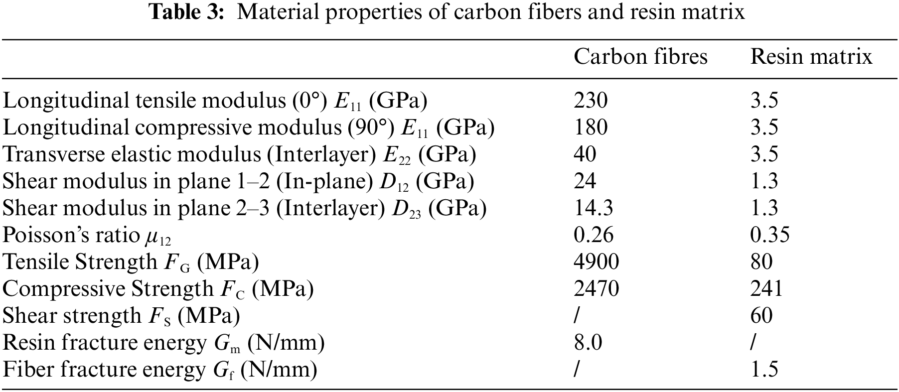
| E11 | Longitudinal tensile modulus |
| E22 | Transverse elastic modulus (Interlayer) |
| D12 | Shear modulus in plane 1–2 (In-plane) |
| D23 | Shear modulus in plane 2–3 (Interlayer) |
| μ12 | Poisson’s ratio |
| Gm | Resin fracture energy |
| Gf | Fiber fracture energy |
| Tensile fiber damage factor | |
| Compressive fiber damage factor | |
| Tensile composite matrix damage factor | |
| Compressive composite matrix damage factor | |
| F | Strength |
| S | Shear |
| C | Compression |
| G | Tensile |
| x | Orthogonal direction x |
| y | Orthogonal direction y |
| α | Material property coefficient 1 adjusting the influence of shear stress |
| β | Material property coefficient 2 adjusting the influence of shear stress |
The demand for lightweight, high-performance materials for applications in the defence industry, aeronautical and civil engineering is growing quickly with the development of science and human society [1–5]. Thus, structural material design to satisfy the requirement of lightweight on the one hand and high ballistic-proof performance on the other hand becomes a challenge. In this situation, bionic materials, such as desert lizards, bone, shells, and bamboo with lightweight and high-strength properties, have inspired much research in structural materials design by imitating the structures and features of natural organisms since the natural materials after millions of years of evolutionary developments usually have higher performance and better structures with relatively weak materials [6–8].
Among those bionic materials, abalone-like structures have obtained remarkable attention for the design of impact-resistant material [9–11]. The white clam shell is studied concerning the microstructure and mechanical properties. It was demonstrated that the microstructure characteristics and the diversity of material properties among the different layers enhanced the white calm shell’s mechanical and crack arrest properties [9,12,13]. The white clam shell comprises 95% lamellar calcium carbonate (CaCO3) and 5% organic matter (protein and polysaccharide). The mineralized biological materials have relatively higher compressive strength, while the organic materials have higher ductility, toughness, and tensile strength because they are fibrous. Thus, the mineralized materials serve better in compression and organic materials in tension working conditions. In other words, mineralized components provide load-bearing capacity, whereas organic materials provide toughness and viscoelastic damping [10]. Although the organic material in the white clamshell is only 5%, it controls the configuration of crystals, thus playing an essential role in improving the toughness [14,15]. The toughness of the white calm shell can reach more than 3000 times that of a single mineralized layer. Thus, many studies have demonstrated the better toughness and strength of multi-layered structures with alternating soft and hard phases [16,17]. Wang et al. [18] fabricated a layered cross-structure ceramic tile bonded with resin and impacted it with a drop hammer. The experimental results show that the layered ceramic tiles can limit crack propagation and deflect cracks. Regarding numerical simulation, Grujicic et al. [19] established a B4C/polyurea composite model to study the performance under the impact of solid cylinder projectiles. The results show that the B4C/polyurea composite has a better ballistic protection effect than the single B4C material. The metals are also chosen as a layer of the lamellar shell in the bionic structure design [20,21]. Flores-Johnson et al. bonded the 7075 aluminium alloy blocks with epoxy resin to create certain surface fluctuation and interface bonding strength. The numerical simulation showed that the energy absorption capacity of the laminated aluminium alloy plate is much better than that of the whole plate with the same thickness. The metal hybrid method can effectively solve the problem of low energy absorption efficiency of Carbon Fiber Reinforced Polymer (CFRP) under lateral crushing load, and the application prospect of the hybrid tube can be better explored through the related crashworthiness design. More importantly, the lateral crushing behavior of carbon fiber reinforced plastic/aluminium (CFRP/AL) hybrid tubes under different parameter configurations were analysed to improve the mechanical performance of CFRP tubes significantly [22–25]. Vecchio [26] prepared a high-performance Ti/Al3Ti composite material using the layer self-assembly method. The crack growth curve of Ti/Al3Ti composite material is similar to that of titanium alloy but with higher stiffness and lower density. Chandler et al. [27] prepared the biomimetic polyvinyl alcohol (PVA)/montmorillonite (MMT) nanomembrane materials and used them as the surface layer of high-performance cement materials. The composite materials showed excellent impact resistance. Despite the various research in the literature focusing on the mechanical properties of the bionic structure, the impact-resistant armor inspired by inorganic-organic multi-layer bionic configuration is very limited.
Apart from the above inorganic-organic multi-layer bionic configuration, the choice of the layers’ material is another aspect of improving the performance of the protective armor [28]. The traditional protective armor was based on pure metals, such as steel and aluminium [29,30]. Later, ceramic/fiber composites are proposed. The ceramic material has high compressive strength to crush the bullet, and the fiber composite material as the back plate can absorb the remaining energy of the projectile. Fiber composite materials used to manufacture armor structures are mainly high-modulus, high-temperature resistant, high-performance fibers with high fracture strain [31]. The protective performance of this ceramic/fiber composite armour is significantly improved compared to the traditional material. Also, lightweight bullet-proof armor materials, such as Al2O3, aluminium alloy, woven and Ultrahigh Molecular Weight Polyethylene (UHMWPE) fiber, have a convenient process, noticeable weight reduction, and good impact resistance compared with traditional metal bullet-proof materials [31,32]. UHMWPE fiber is a high-performance fiber with low density, high modulus and high specific strength. Thus, it has a remarkable ability to absorb impact energy, making it widely used in bullet-proof products [33,34]. Previous research is mainly focused on armour composed of pure metals or few materials. However, owing to its complexity, multi-layer amour with different layer sequences and thicknesses should be studied computationally and experimentally to build the theory of designing multi-layer amour.
Recent literature studied the design of armour under bullet impact from other perspectives [35]. A theoretical impacting model of the ceramics/aluminium composite armour is built to analysis the bullet-proof performance of armour rather than describe the armour as a single component [36]. The non-equivalent mechanical properties are performed and the fracture and erosion of ceramic under high strain rate and pressure of ceramic in the armour during perforation have been considered [37]. The ballistic performance of moderately thick (relatively thick compared to projectiles’ diameter) metallic armour is studied and the existing incompatible ballistic results are analysed [38]. A cartography showing injection regions of the projectile is investigated to analysis of the material damage [39]. A surface-based cohesive material model using traction-separation constitutive law between adjacent layers is built to study the amours’ ballistic penetration behaviors [40]. An alumina/ceramic armor with strong confinement on the penetration process of the projectile is performed for testing the influence of constraint [41]. The impact tests performed with incendiary bullets of 7.62 mm caliber against multi-layer armor containing alloy and ultra-high-molecular-weight polyethylene are presented [42]. The ballistic performance of the armor against a flat-nosed projectile was investigated experimentally and numerically [43]. The role of the hot curing pressure on the influence of the bullet-proof performance of composite armor is quantified and included in finite element models [44]. The dynamic response of a sandwich armor, constructed with Kevlar/carbon fiber/epoxy as top and bottom skins and the core of the triangular corrugated aluminium structure is studied [45]. In our previous study [46], an origami shield composed of modular composite plates has been designed and manufactured. However, although the above-mentioned studies have analyzed the armour from different perspectives, such as the constraint method, bullet shape, curing processes, and failure models, few studies have focused on the bio-inspired inorganic-organic multi-layer mechanism and a consensus regarding the design of modular composite plates with different layer sequences and thicknesses is lacking. In other words, research in the literature did not systematically optimize layer stacks (layer thickness and sequence) with different strength, toughness, stiffness and density properties. This work aims to assess the bullet-proof performance of abalone-like Al2O3 ceramics/UHMWPE/CFRP composite armour by finite element model and ballistic test. The complete characterization model and related parameters of large material deformation, failure and fracture of Al2O3 ceramics and CFRP multi-layer composite is introduced. Based on the different properties of Al2O3 ceramics, UHMWPE and CFRP in hardness, strength and energy absorption, 3D finite element models of a multi-layer protective composite plate with different layer thicknesses and sequences are established. Then, a finite-element analysis (transient, nonlinear dynamic) is performed to simulate the ballistic impact and optimize its layer stacks scheme inspired by an abalone shell. The physical samples of the composite plate are impacted by a gun to verify its bullet-proof performance for use as armour.
This work provides design theory for developing lightweight, high-performance, multi-layer composite protective armours. Based on the analysis of the above research, the protective armour is designed in a multi-layer composite plate. The material models and the finite element models to simulate the bullet-proof performance are presented in Section 2. The fabrication process and ballistic experiment are presented and discussed in Section 3. The main conclusion is summarized in Section 4.
2 Material Models and Finite Element Modelling
The constitutive models of Al2O3 ceramics and carbon fibre composites were established and compiled into the user’s material subroutine in Abaqus to accurately simulate material properties during the impact. Considering the mechanical properties at high strain rates and the evolution characteristics of damage and fracture, the characterization model of the composites is divided into two parts: First, the material properties model at the high strain before failure is established. Then, a description function including elastic energy, plastic strain energy and damage parameters after the damage is constructed and combined with the basic characterization model. Finally, a complete characterization model considering large deformations and failure under high-speed impact is obtained based on the aforementioned two parts.
2.1.1 JH-2 Constitutive Model of Al2O3 Ceramics
The Johnson-Holmquist constitutive model (JH-2 model) [47] consists of three main parts: (1) the materials’ strength is expressed in a smooth function of pressure-related yield surface; (2) the transition from the undamaged state to the start of damaged state to the final fracture state [48]; (3) equation of state (EOS) of pressure-density relationship considering expansion effect. The constitutive model is illustrated as follows.
The Relation between Stress and Strength
The normalized equivalent stress
where
The aforementioned equivalent stress, including
It is assumed that equivalent intact
where M, N, I, J and K are material property constants,
The damage accumulation criterion is similar to the Johnson-Cook fracture model [49] and the JH-1 model [50]. The damage D is related to plastic strain and can be calculated by:
where
where A1 and A2 are the material property constants.
The hydrostatic pressure P during the elastic state is calculated by:
where
Taking into account the bulking after the damage, the pressure hydrostatic P is reformulated by:
where the pressure increment
where k represents the loss percentage of elastic energy,
2.1.2 The Constitutive Model of Carbon Fiber Reinforced Polymer (CFRP) Composites
Elastic Model
The matrix of CFRP is assumed to have a bilinear elastic-plastic stress-strain behavior. Before the stress reaches the initial yield limit, the matrix behaves homogenously and linearly. After the stress reaches the initial yield limit, the matrix behaves linearly plastically and is assumed to be isotropic [51].
Yarns of CFRP are assumed to be isotropic transversely. Its elastic properties can be calculated from initial elastic engineering constants (E11, E22, G12, G13, μ12 and μ23) [52,53]:
where
Based on the above initial elastic engineering constants, the constitutive model of transversely isotropic material in the elastic phase is given below:
where
Thus,
Damage Model
The final failure of the material is caused by the accumulation of damage. Damage mechanisms of the 3D Hashin [54,55] are introduced in this paper to predict the failure behavior. According to the damage directions of the fiber’s longitudinal and matrix’s transverse, damage mechanisms of the 3D Hashin are indicated by tensile fiber damage factors
Tensile fibre damage initiation criterion:
Compressive fibre damage initiation criterion:
Tensile composite matrix damage initiation criterion:
Compressive composite matrix damage initiation criterion:
where F and σ are strength and stress, subscripts S, C and G represent shear, compression and tensile of yarns, subscripts x, y and z represent three orthogonal directions, α and β are material property coefficients adjusting the influence of shear stress and is set to 1,
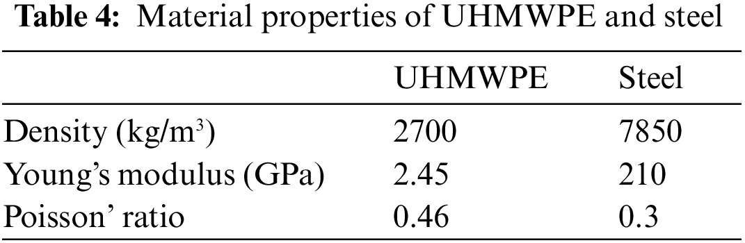
In order to study the bullet-proof performance of composite plates with different sequences and thicknesses, the composite plates were impacted by a 12.7 mm armour-piercing projectile (API) with a velocity of 400 m/s [38]. The geometry model was generated and pre-processed by the commercial software SolidWorks 2018. Based on the constitutive relation model and data provided in Section 2.1, the finite element model of the target plate is established by Abaqus/Explicit (Version 6.11). In the finite element model, the 100 mm × 100 mm × 10 mm multi-layer composite square plates (see Fig. 1a) with different sequences and thicknesses (see Fig. 2) are set as test samples. The location of displacement recording point P is shown in Fig. 1a. Point P, rather than the central point at the back side of the UHMWPE plate (the point of impact), is selected for displacement comparison in Case 1~4 because the material at the impact point will splash and not reflect the deformation of the plate. Inspired by the inorganic-organic multi-layer bionic configuration, the thickness and sequences of each material are set in Table 1. The multi-layer composite plates are composed of three materials: CFRP, Al2O3 ceramic and UHMWPE. The grids are composed of reduced-integration linear hexahedral elements (C3D8R). It is assumed that the layers with different materials are tied together using Tie Constraints in Abaqus. The multi-layer composite plate is clamped at the edge boundaries. The geometry model of the bullet is shown in Fig. 1b. The physical properties of the materials used in the multi-layer composite samples and the bullet are listed in Tables 2–4. Case 1~4 is tested to analyse the influence of layer sequence and thickness on the impact resistance under the same impact. The impact was simulated in six hours using a 3.19 GHz 16-Core 12th Gen Intel Core i9, running Windows 10 Professional 19044.2364.
Figure 1: The geometry model and dimensions: (a) The composite plate, (b) The bullet
Figure 2: Composite stack diagram of Case 1~4: (a) Case 1, (b) Case 2, (c) Case 3, (d) Case 4
The structures in Case 1~4 are meshed with C3D8R elements, as shown in Fig. 3. The number of elements in Case 1~4 is 194087, 196304, 194087 and 196304, respectively. The four sides of the composite samples are fixed. The bullet is applied to the predefined central field of plates. The velocity of the bullet is 400 m/s perpendicular to the plate surface. Due to the large deformation of impact, geometric nonlinearity is considered, and impact time is set to 200 μs.
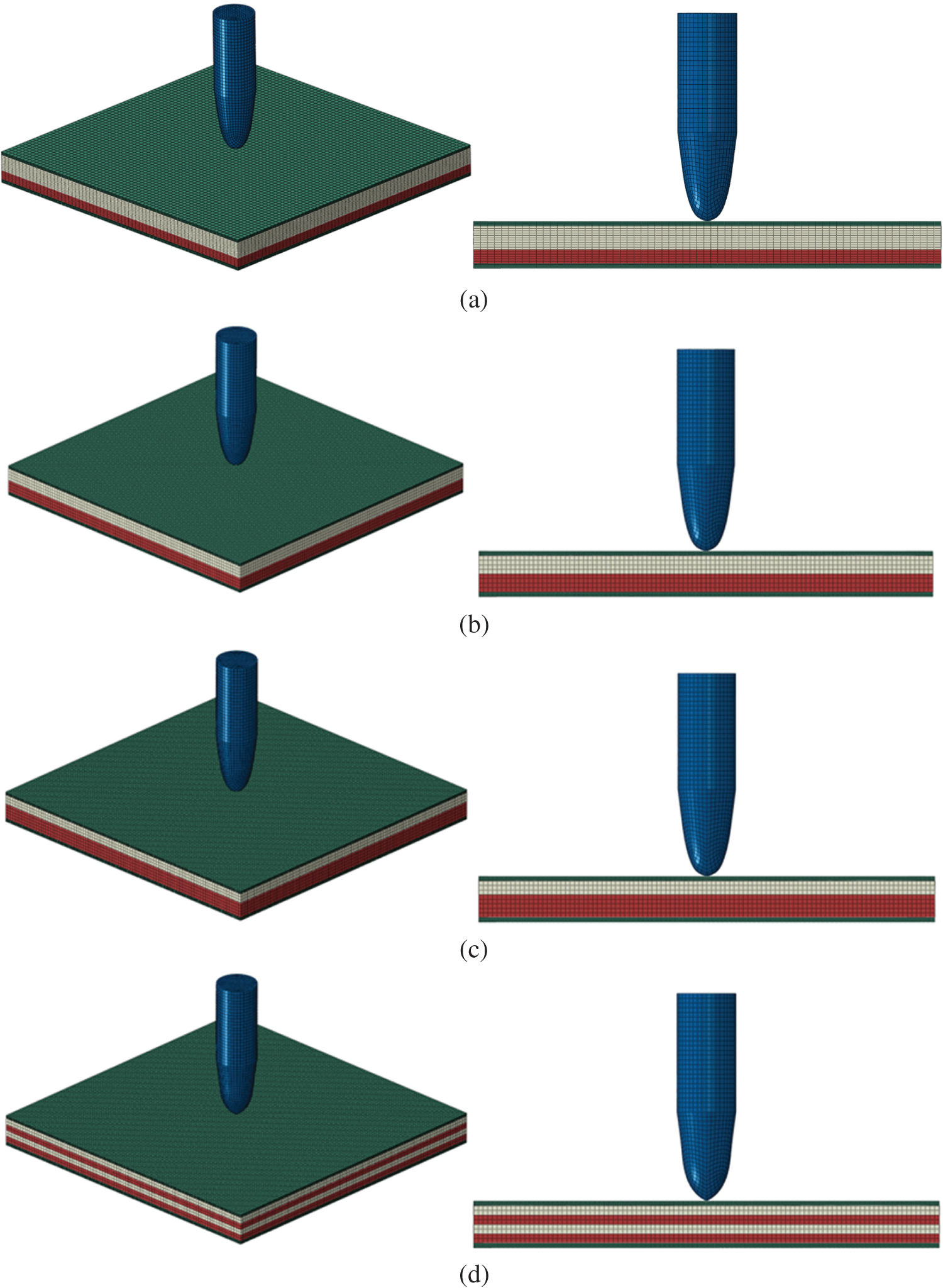
Figure 3: The finite element models in Case 1~4: (a) Case 1, (b) Case 2, (c) Case 3, (d) Case 4
Taking Case 1 and 2 as an example, the sequence of multi-layer composite is set considering their physical properties for improving the protection effectiveness. The first layer CFRP is a lightweight and high specific strength material. After penetrating the first layer, the bullet crushes the second layer (ceramics). The ceramic has high hardness and strength. It absorbs the energy of the bullet by deformation and damage. Finally, with high stiffness and support performance, UHMWPE and CFRP layers stop splatted shrapnel.
The stress contours of each layer of the multi-layer composite plates in Case 1, Case 2, Case 3 and Case 4 when the velocity of the bullet reaches minimum are shown in Figs. 4–7, respectively. The stress contours of the bullet when the velocity of the bullet reaches minimum in Case 1, Case 2, Case 3 and Case 4 are shown in Fig. 8.
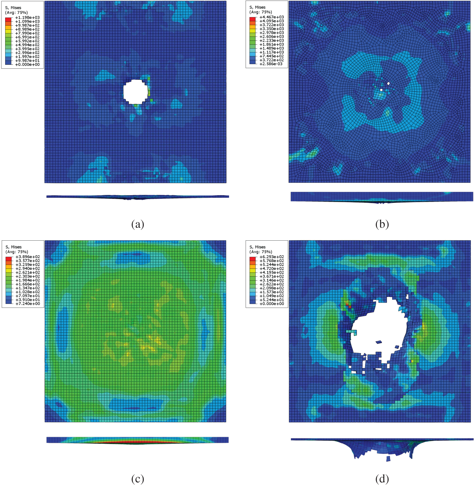
Figure 4: Stress contours of each layer when the velocity of the bullet reaches a minimum in Case 1: (a) First CFRP layer (1 mm), (b) Al2O3 Ceramic layer (5 mm), (c) UHMWPE layer (3 mm), (d) Second CFRP layer (1 mm) (Unit: MPa)
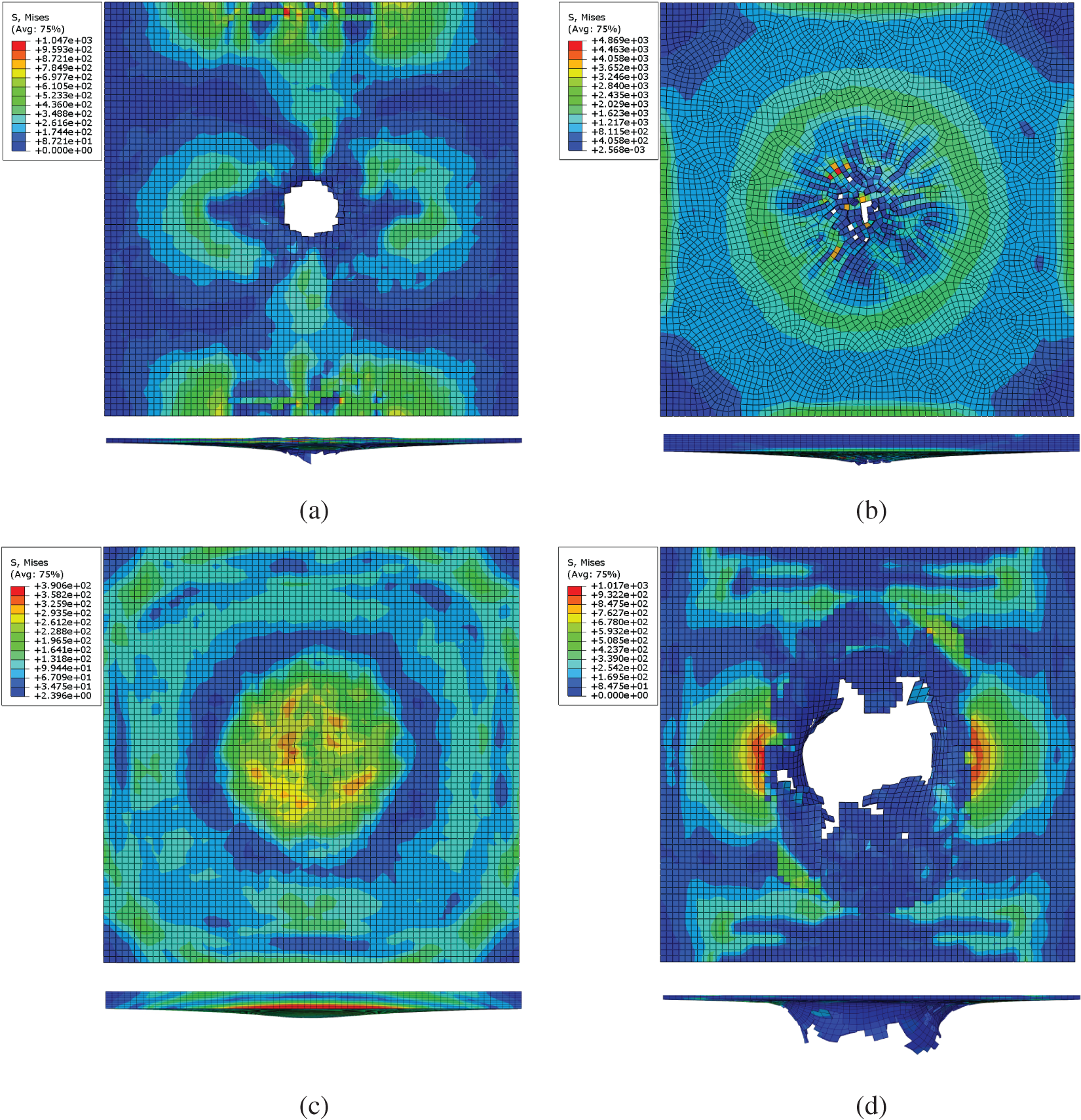
Figure 5: Stress contours of each layer when the velocity of the bullet reaches a minimum in Case 2: (a) First CFRP layer (1 mm), (b) Al2O3 Ceramic layer (4 mm), (c) UHMWPE layer (4 mm), (d) Second CFRP layer (1 mm) (Unit: MPa)
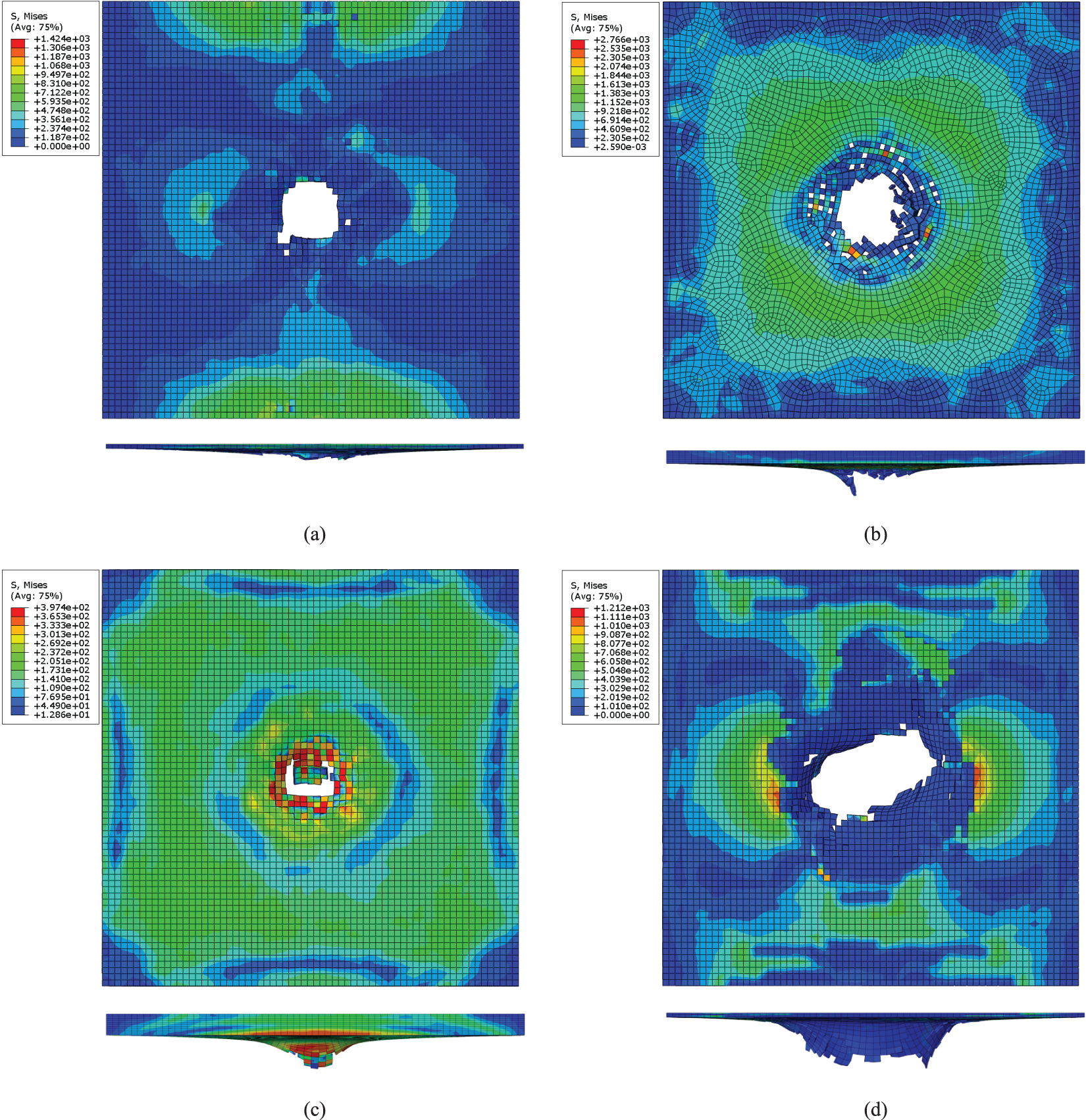
Figure 6: Stress contours of each layer when the velocity of the bullet reaches a minimum in Case 3: (a) First CFRP layer (1 mm), (b) Al2O3 ceramics layer (3 mm), (c) UHMWPE layer (5 mm), (d) Second CFRP layer (1 mm) (Unit: MPa)
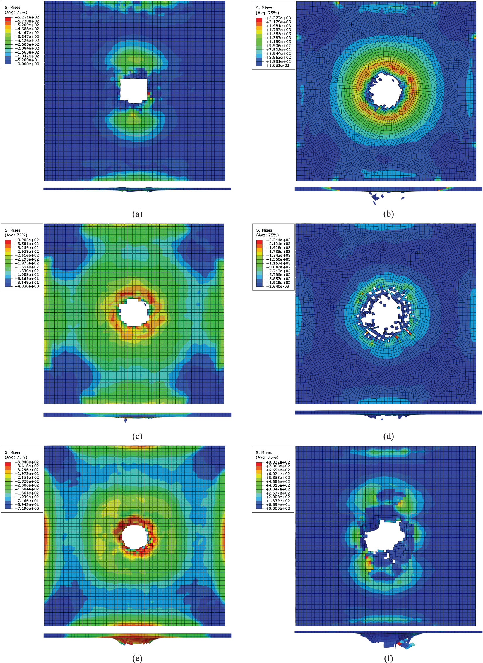
Figure 7: Stress contours of each layer when the velocity of the bullet reaches a minimum in Case 4: (a) First CFRP layer (1 mm), (b) First Al2O3 ceramic layer (2 mm), (c) First UHMWPE layer (2 mm), (d) Second Al2O3 ceramic layer (2 mm), (e) Second UHMWPE layer (2 mm), (f) Second CFRP layer (1 mm) (Unit: MPa)
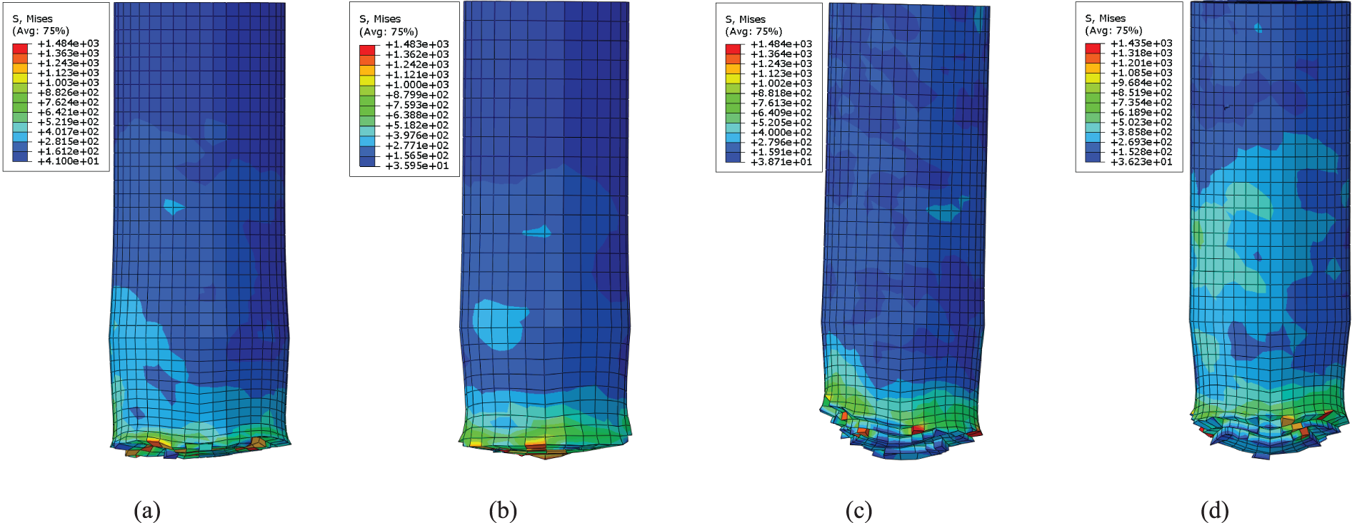
Figure 8: Stress contours of the velocity of the bullet reach a minimum in Case 1~4: (a) Case 1, (b) Case 2, (c) Case 3, (d) Case 4 (Unit: MPa)
For Case 1 and 2, the first CFRP layer and the Al2O3 Ceramic were penetrated after being impacted by the bullet, while the UHMWPE layer was not. The second CFRP layer is stretched out and broken with a hole because of the large deformation conducted from the UHMWPE layer. It demonstrated that the multi-layer composite plate of Case 1 and 2 is not penetrated and satisfies the bullet-proof requirements. For Case 1, the maximum stress of the first CFRP layer, Al2O3 ceramic, UHMWPE and the second CFRP layer are approximately 1198, 4467, 390 and 629 MPa, respectively. The maximum stress of the bullet is approximately 1484 MPa. For Case 2, the maximum stress of the first CFRP layer, Al2O3 ceramic, UHMWPE and the second CFRP layer are approximately 1047, 4869, 391 and 1017 MPa, respectively. The maximum stress of the bullet is approximately 1483 MPa. The Al2O3 ceramic layer plays a crucial role in absorbing the bullet’s energy in the protective plates. The UHMWPE layer absorbs the attenuated bullet fragments and stops the bullet because of its high toughness.
For Case 3, all the layers are broken with a hole after the bullet’s impact. The UHMWPE layer is damaged partly and not penetrated throughout. It demonstrates that the bullet is embedded in the UHMWPE layer. The maximum stress of the first CFRP layer, Al2O3 ceramic, UHMWPE and the second CFRP layer are approximately 1424, 2766, 397 and 1212 MPa, respectively. The maximum stress of the bullet is approximately 1484 MPa. The bullet-proof performance of Case 2 is better than Case 3 shown in Table 5.
For Case 4, all the layers were penetrated throughout after being impacted by the bullet. The maximum stress of the first CFRP layer, the first Al2O3 ceramic layer, the first UHMWPE layer, the second Al2O3 ceramic layer, the second UHMWPE layer and the second CFRP layer are approximately 625, 2377, 390, 2314, 394 and 803 MPa, respectively. The maximum stress of the bullet is approximately 1435 MPa. The only difference between Case 2 and Case 4 is the sequences of the Al2O3 ceramic layer and the UHMWPE layer. It demonstrated that the first Al2O3 ceramic layer plays a crucial role in the bullet-proof process. Reducing the thickness of the first Al2O3 ceramic layer and placing it behind the UHMWPE layer will reduce the overall bullet-proof performance of the multi-layer composite. The maximum stress of the second UHMWPE layer is 1% higher than that of the first UHMWPE layer. The maximum stress of the second CFRP layer is 28% higher than that of the first CFRP layer. It demonstrated that the maximum stress values in the first layers, which are in the later stages of bullet penetration, are reduced compared with those in the second layers in the earlier stages of bullet penetration.
The inorganic-organic multi-layer bionic configuration is inspired by the structural mechanics of a white clam shell, which comprises lamellar thick calcium carbonate (CaCO3) and thin organic matter (protein and polysaccharide) [9,12,13]. The above simulation results, showing the superior performance of Case 1 and Case 2 (thick Al2O3 ceramic and thin UHMWPE), confirm the effectiveness of the bionic mechanism of the white clam shell. Figs. 9–12 show the displacement contour of the multi-layer composite plates of Case 1, Case 2, Case 3 and Case 4, respectively.
Figure 9: The displacement contour of the multi-layer composite plate in Case 1 at different moments: (a) The beginning of impact simulation (0 μs), (b) The velocity of the bullet reaches a minimum (82 μs), (c) The end of impact simulation (200 μs)
Figs. 9a, 10a, 11a and 12a are the displacement contours at the start of impact in 0 μs. Figs. 9b, 10b, 11b and 12b show the displacement contour when the bullet velocity reaches a minimum in 82, 94, 102 and 62 μs, respectively. Figs. 9c, 10c, 11c and 12c are the displacement contours at the end of impact in 200 μs.
Figure 10: The displacement contour of the multi-layer composite plate in Case 2 at different moments: (a) The beginning of impact simulation (0 μs), (b) The velocity of the bullet reaches a minimum (94 μs), (c) The end of impact simulation (200 μs)
Figure 11: The displacement contour of the multi-layer composite plate in Case 3 at different moments: (a) The beginning of impact simulation (0 μs), (b) The velocity of the bullet reaches a minimum (102 μs), (c) The end of impact simulation (200 μs)
Figure 12: The displacement contour of the multi-layer composite plate in Case 4 at different moments: (a) The beginning of impact simulation (0 μs), (b) The velocity of the bullet reaches a minimum (62 μs), (c) The end of impact simulation (200 μs)
Significant damage occurred at the central point after impact. Thus, the displacement history of the damaged flying splinters at the centre point cannot reflect the energy change of the composite plates. Therefore, a displacement recording point P rather than the central point at the back side of the last layer of the UHMWPE plate is selected for displacement comparison in Case 1~4. The displacement recording point is located at the point P in Fig. 1a in the last layer of the UHMWPE plate’s surface on which the bullet exited. Fig. 13 illustrates the displacement history of the point P. The maximum displacements of the point P of Case 1~4 are recorded as 3.59, 3.80, 5.46 and 0.05 mm at 82, 94, 102 and 62 μs, respectively. The displacement in Case 4 is significantly less than in Case 1~3. Case 3 shows the most significant maximum displacement because the kinetic energy of the bullet is fully absorbed by the composite plate, while Case 4 shows the most minor maximum displacement because the composite plate is thoroughly penetrated by the bullet and the remaining kinetic energy of the bullet is the largest. Also, the time of the maximum displacement is increased from Case 4 to Case 1 to Case 2 to Case 3, aligning with the values of the maximum displacement.
Figure 13: Displacement history of point P on the right side of the multi-layer composite plate in Case 1, Case 2, Case 3 and Case 4
Figs. 14–17 show the bullets’ velocity and kinetic energy history during impact. After the bullet’s velocity in Case 1 and Case 2 decreased to 0 m/s, the bullet rebounded with a constant velocity of approximately 60 and 40 m/s, respectively. In Case 3, the plate experiences substantial deformation and the appearance of cracks at the impact point, although it neither rebounds nor gets penetrated. The value of kinetic energy after the rebounding is close to 47 kJ. The bullet’s velocity decreased to 0 m/s and is embedded on the plate with 0 kJ kinetic energy. For Case 4, the plate was penetrated throughout by the bullet at an exit velocity of 195 m/s with 511 kJ kinetic energy, the kinetic energy of the bullet is not fully transferred to the composite plate. The impact time, velocity of the bullet, kinetic energy and other parameters in Case 1~4 are listed in Table 6. It is concluded that the bullet-proof performance of Case 2 is optimal except for the overweight Case 1.
Figure 14: The history of the bullet’s velocity and kinetic energy during the impact of Case 1
Figure 15: The history of the bullet’s velocity and kinetic energy during the impact of Case 2
Figure 16: The history of the bullet’s velocity and kinetic energy during the impact of Case 3
Figure 17: The history of the bullet’s velocity and kinetic energy during the impact of Case 4
Taking Case 3 in Fig. 2 as an example, the Al2O3 ceramic layer is placed upon the CFRP and UHMWPE layers with sticky membrane films between each adjacent layer. After putting another CFRP layer, the CFRP out of the boundary is tailored. The stack sequence of the placed multi-layer composite sample is shown in Fig. 18. After pumping the vacuum, those placed layers of plates were put into an autoclave (see Fig. 19a) and heated to 195°C for 150 min, which makes sticky membrane films sticky (see Fig. 19b). After being printed in black colour, the formed multi-layer composite is shown in Fig. 20.
Figure 18: The stack sequence of multi-layer composite
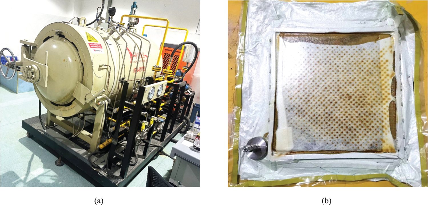
Figure 19: The fabrication of multi-layer composite: (a) the autoclave, (b) the formed multi-layer composite
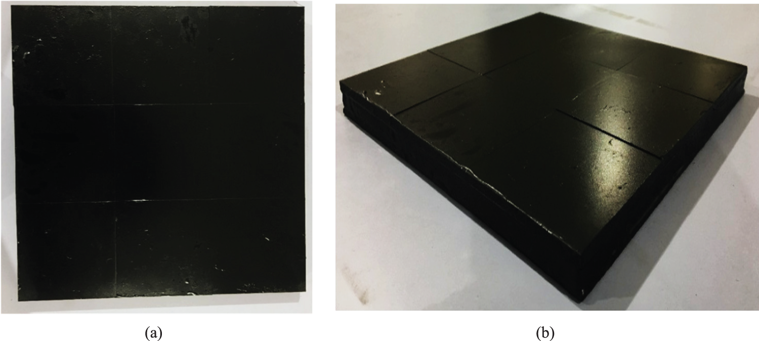
Figure 20: Test sample of the multi-layer composite after printed in black color: (a) top view of the sample, (b) oblique view of the base
In this section, in order to verify the bullet-proof properties and the simulation results and provide guidance for composite design, the multi-layer composite samples in Case 2~4 (see Table 1) were impacted in the China North Industries Group Corporation Limited Northwest Institute of Mechanical & Electronical Engineering. The 12.7 mm API is used as a bullet with a velocity of 400 m/s. The deviation of speed should be guaranteed within 30 m/s. The samples were fired from a gun at a distance of 4.3 m with an incident angle of 0°.
The platform for high-speed impact tests is built according to MIL-STD-662E standards [48]. The ballistic test platform consists of a fixed base, a chronoscope, a velocity measurement target, a baffle, and a ballistic gun, as shown in Fig. 21. Two velocity measurement targets can record the time the bullet passes. Thus, the bullet’s velocity can be calculated by the distance of targets and passed time. Since the bullet impact has high speed, the strain gauges attached to the surface of the composite plate were damaged and fell off under the influence of shock waves. Thus, the strain gauges cannot measure the strain change at the time of the bullet impact. The impact test carried out by the China North Industries Group Corporation Limited Northwest Institute of Mechanical & Electronical Engineering is a valid way to verify the effectiveness of simulation according to literature about the bullet-proof test [48,56–59].
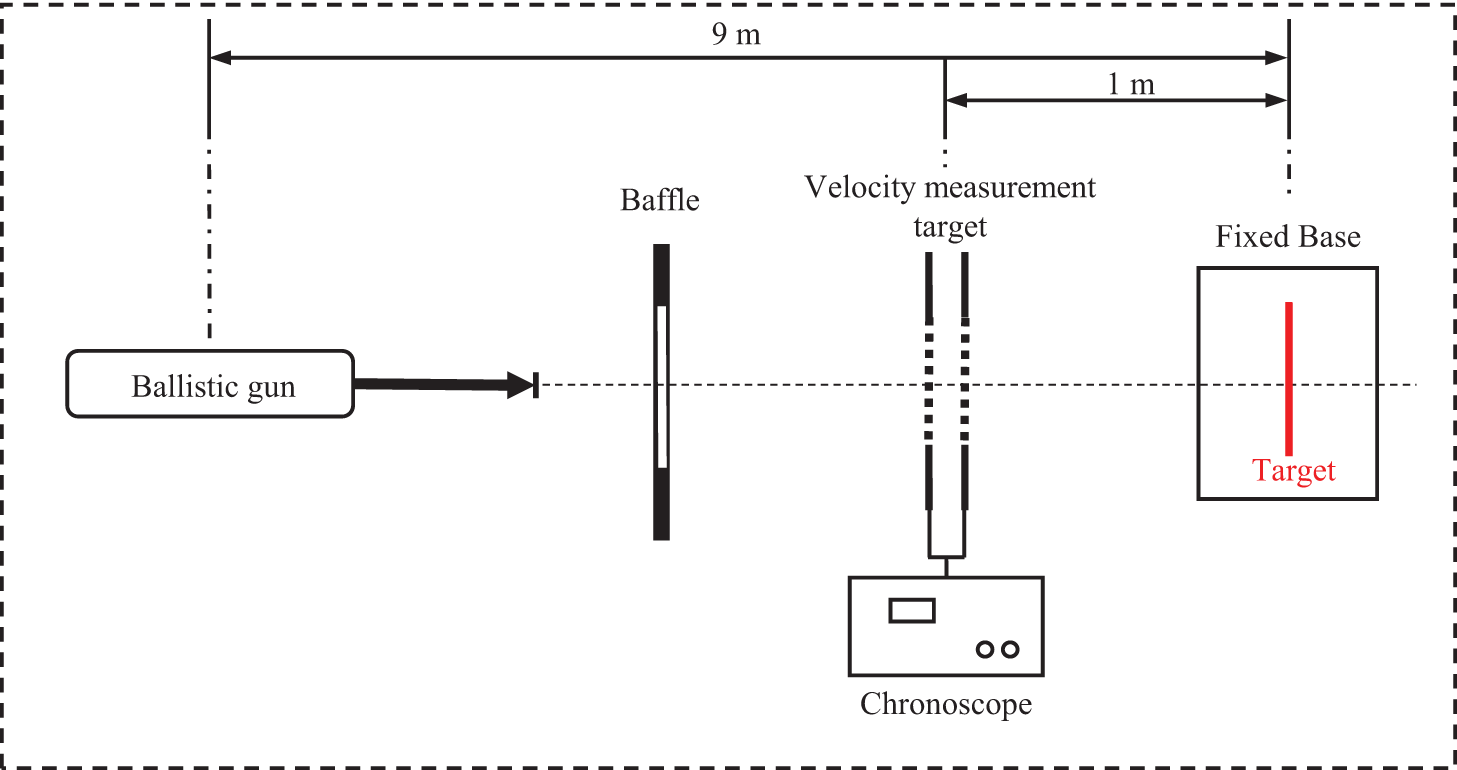
Figure 21: Schematic diagram of ballistic experiment
In the test, the three multi-layer composite samples in Case 2~4 (see Table 1) were fired 3 × 4 = 12 times, of which 3 × 3 = 9 times was effective fire, and the rest 1 × 3 = 3 times were speed calibration, bullet jamming, etc. Fig. 22 shows the appearance of the test samples in Case 2~4 after being impacted by the bullets. Samples of Case 2 and Case 3 show the mosaic situation since it is not penetrated, while that of Case 4 is penetrated. The bullet-proof tests show the same result as the simulation results.
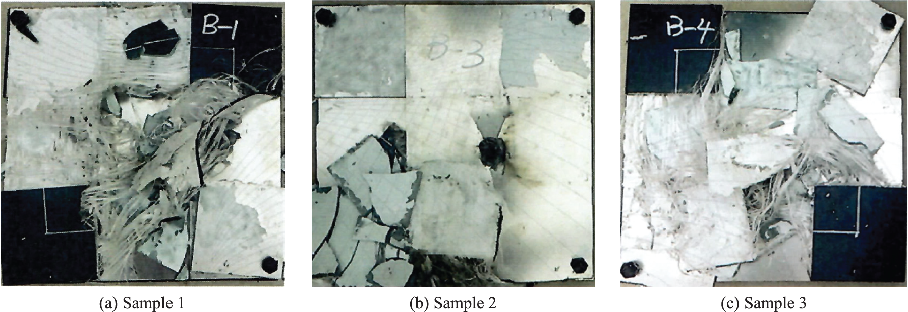
Figure 22: Failure patterns of composite armor
In this study, a series of multi-layer protective armour with different sequences and thicknesses of materials impacted by a 12.7 mm armour-piercing incendiary (API) were designed, modelled, simulated, fabricated and tested. Based on the results obtained in the present work, the following main summary remarks and conclusions can be drawn:
1. A geometry model has been constructed for the multi-layer composite plates. To mimic the architecture of the white clam shell which comprises of lamellar thick calcium carbonate (CaCO3) and thin organic matter (protein and polysaccharide), four cases with different layer sequences and thicknesses are modelled.
2. The impact of the abovementioned multi-layer composite plates by a 12.7 mm armor-piercing projectile, incident normally, is simulated using an explicit and nonlinear dynamic Abaqus finite-element analysis, to assess the potential of the four composite plates for use in ballistic-armor applications. The above simulation results, showing superior performance of Case 1 and Case 2 (thick Al2O3 ceramic and thin UHMWPE), confirm the effectiveness of the bionic mechanism of the white clam shell. The numerical results obtained from the 3D finite element models demonstrated the influences of the layer sequences and thicknesses and guided the optimum choice of the stack of the multi-layer composite.
3. The multi-layer composite was fabricated by pumping the vacuum into an autoclave and heating it to 195°C for 150 min.
4. The effectiveness of the simulation was verified by conducting the ballistic-proof test. For impact by a given real projectile at a fixed incident velocity in the China North Industries Group Corporation Limited Northwest Institute of Mechanical & Electronical Engineering, the stack of Case 1 (1 mm CFRP/4 mm Al2O3 ceramic/4 mm UHMWPE/1 mm CFRP) has the highest ballistic penetration resistance than other stacks. The simulation results with different layer sequences and thicknesses reasonably correlate with the experimental results.
The conclusions are helpful for the design of protective multi-layer structures. Future work needs to be done to study the concurrent design of the multi-layer structure and the motion of origami armor.
Acknowledgement: The authors express their appreciation to the National Natural Science Foundation of China, Shaanxi Provincial Key Science and Technology Innovation Team, the Young Talent Fund of Association for Science and Technology in Shaanxi, China and the Chinese Studentship Council.
Funding Statement: This work is funded by the National Natural Science Foundation of China (W. Zhang, Grant No. 12220101002), Shaanxi Provincial Key Science and Technology Innovation Team (Y. Xu, Grant No. 2023-CX-TD-14), the Young Talent Fund of Association for Science and Technology in Shaanxi, China (D. Jia, Grant No. 20230240) and the Chinese Studentship Council (D. Jia, Grant No. 201908060224).
Author Contributions: The authors confirm contribution to the paper as follows: study conception and design: Dongsheng Jia; data collection: Liangdi Wang; analysis and interpretation of results: Dongsheng Jia, Yingjie Xu, Jihong Zhu; draft manuscript preparation: Dongsheng Jia, Weihong Zhang. All authors reviewed the results and approved the final version of the manuscript.
Availability of Data and Materials: The data that support the findings of this study are available from the first and corresponding authors upon reasonable request.
Conflicts of Interest: The authors declare that they have no conflicts of interest to report regarding the present study.
References
1. Brischetto, S., Torre, R., Cesare, D. (2023). Three dimensional coupling between elastic and thermal fields in the static analysis of multilayered composite shells. Computer Modeling in Engineering & Sciences, 136(3), 2551–2594. https://doi.org/10.32604/cmes.2023.026312 [Google Scholar] [CrossRef]
2. Kang, G., Ouyang, Q., Chen, P. (2023). Three-dimensional numerical manifold method for low-speed impact simulation of PBXs. The International Conference on Computational Experimental Engineering and Sciences, 26(1), 1. https://doi.org/10.32604/icces.2023.010508 [Google Scholar] [CrossRef]
3. Li, Z., Ji, J., Vu Quoc, L., Izzuddin, B. A., Zhuo, X. (2021). A 3-node no-rotational triangular finite element for non-Smooth, folded and multi-shell laminated composite structures. Computer Modeling in Engineering & Sciences, 129(2), 485–518. https://doi.org/10.32604/cmes.2021.016050 [Google Scholar] [CrossRef]
4. Ma, K., Liu, Z., Zhang, X., Xiao, B., Ma, Z. (2021). Fabrication of high strength carbon nanotube/7055Al composite by powder metallurgy combined with subsequent hot extrusion. Science China Technological Sciences, 64(5), 1081–1091. [Google Scholar]
5. Huo, Y., Tian, Y., Pu, S., Shi, T., Xia, Q. (2021). Bilateral filter for the optimization of composite structures. Computer Modeling in Engineering & Sciences, 127(3), 1087–1099. https://doi.org/10.32604/cmes.2021.015694 [Google Scholar] [CrossRef]
6. Xu, S., Li, W., Li, L., Li, T., Ma, C. (2022). Crashworthiness design and multi-objective optimization for bio-inspired hierarchical thin-walled structures. Computer Modeling in Engineering & Sciences, 131(2), 929–947. https://doi.org/10.32604/cmes.2022.018964 [Google Scholar] [CrossRef]
7. Chen, X., Wang, D., Dou, W., Wang, Y., Yang, Y. et al. (2020). Design and manufacture of bionic porous titanium alloy spinal implant based on selective laser melting (SLM). Computer Modeling in Engineering & Sciences, 124(3), 1099–1117. https://doi.org/10.32604/cmes.2020.09619 [Google Scholar] [CrossRef]
8. Yang, W., Li, J., Yang, J., Wei, L. (2015). Numerical simulation of an experienced farmer lifting tubers of cassava for designing a bionic harvester. Computer Modeling in Engineering & Sciences, 104(6), 471–491. https://doi.org/10.3970/cmes.2015.104.471 [Google Scholar] [CrossRef]
9. Liang, Y., Zhao, Q., Li, X., Zhang, Z., Ren, L. (2016). Study of the microstructure and mechanical properties of white clam shell. Micron, 87, 10–17. [Google Scholar] [PubMed]
10. Chen, P. Y., McKittrick, J., Meyers, M. A. (2012). Biological materials: Functional adaptations and bioinspired designs. Progress in Materials Science, 57(8), 1492–1704. [Google Scholar]
11. Wu, K., Ni, Y. (2023). Multiscale structural design and fracture control of high-performance biomimetic materials. The International Conference on Computational Experimental Engineering and Sciences, 26(3), 1–2. [Google Scholar]
12. Meyers, M. A., Chen, P. Y., Lin, A. Y. M., Seki, Y. (2008). Biological materials: Structure and mechanical properties. Progress in Materials Science, 53(1), 1–206. [Google Scholar]
13. Yang, W., Chen, I. H., Gludovatz, B., Zimmermann, E. A., Ritchie, R. O. et al. (2013). Natural flexible dermal armor. Advanced Materials, 25(1), 31–48. [Google Scholar] [PubMed]
14. Sun, J., Bhushan, B. (2012). Hierarchical structure and mechanical properties of nacre: A review. RSC Advances, 2(20), 7617–7632. [Google Scholar]
15. Ritchie, R. O. (2011). The conflicts between strength and toughness. Nature Materials, 10(11), 817–822. [Google Scholar] [PubMed]
16. Cartwright, J. H. E., Checa, A. G., Escribano, B., Sainz-Díaz, C. I. (2009). Spiral and target patterns in bivalve nacre manifest a natural excitable medium from layer growth of a biological liquid crystal. Proceedings of the National Academy of Sciences of the United States of America, 106(26), 10499–10504. [Google Scholar] [PubMed]
17. Meyers, M. A., Chen, P. Y., Lopez, M. I., Seki, Y., Lin, A. Y. M. (2011). Biological materials: A materials science approach. Journal of the Mechanical Behavior of Biomedical Materials, 4(5), 626–657. [Google Scholar] [PubMed]
18. Wang, Z., Sun, Y., Wu, H., Zhang, C. (2018). Low velocity impact resistance of bio-inspired building ceramic composites with nacre-like structure. Construction and Building Materials, 169(2018), 851–858. [Google Scholar]
19. Grujicic, M., Snipes, J. S., Ramaswami, S. (2016). Ballistic impact behavior of nacre-like laminated composites consisting of B4C tablets and polyurea matrix. Journal of Materials Engineering and Performance, 25(3), 977–994. [Google Scholar]
20. Flores Johnson, E. A., Shen, L., Guiamatsia, I., Nguyen, G. D. (2014). Numerical investigation of the impact behaviour of bioinspired nacre-like aluminium composite plates. Composites Science and Technology, 96(2014), 13–22. [Google Scholar]
21. Miao, T., Shen, L., Xu, Q., Flores Johnson, E. A., Zhang, J. et al. (2019). Ballistic performance of bioinspired nacre-like aluminium composite plates. Composites Part B: Engineering, 177(2019), 107382. [Google Scholar]
22. Yang, H., Ren, Y. (2023). Crashworthiness design of CFRP/AL hybrid circular tube under lateral crushing. Thin-Walled Structures, 186, 110669. [Google Scholar]
23. Yang, H., Ren, Y. (2023). Crushing behavior of CFRP/AL hybrid tubes under oblique lateral loading. Polymer Composites, 44(10), 6403–6418. [Google Scholar]
24. Jiang, H., Wang, Y., Ren, Y. (2022). Controllable energy-absorption behaviors of the perforated CFRP tube with an adhesively bonded CFRP patch. Thin-Walled Structures, 181, 110015. [Google Scholar]
25. Jiang, H., Liu, X., Jiang, S., Ren, Y. (2023). Hybrid effects and interactive failure mechanisms of hybrid fiber composites under flexural loading: Carbon/Kevlar, carbon/glass, carbon/glass/Kevlar. Aerospace Science and Technology, 133, 108105. [Google Scholar]
26. Vecchio, K. S. (2005). Synthetic multifunctional metallic-intermetallic laminate composites. JOM Journal of the Minerals Metals and Materials Society, 57(3), 25–31. [Google Scholar]
27. Chandler, M. Q., Sherburn, J. A., Allison, P. G., Moser, R. D., Torres-Cancel, K. A. et al. (2017). Application of bio-inspired nanocomposites for enhancing impact resistance of cementitious materials. International Journal of Impact Engineering, 110, 171–180. [Google Scholar]
28. Lin, G. (2023). Low-velocity impact response of sandwich composite panels with shear stiffening gel filled honeycomb cores. The International Conference on Computational Experimental Engineering and Sciences, vol. 26, no. 3, pp. 1–2. https://doi.org/10.32604/icces.2023.09075 [Google Scholar] [CrossRef]
29. Hilmes, R. (1987). Brassey’s multilingual military dictionary. London: Brassey’s Defence Publishers. [Google Scholar]
30. Santos, V. C., Lopes, P. S., Gärtner, R., Jorge, A. B. (2007). Weight and reliability optimization of a helicopter composite armor using dynamic programming. The International Conference on Computational Experimental Engineering and Sciences, vol. 4, no. 2, pp. 53–58. [Google Scholar]
31. Ramadhan, A. A., Talib, A. R. A., Rafie, A. S. M., Zahari, R. (2012). The Influence of impact on composite armour system kevlar-29/polyester-Al2O3. IOP Conference Series: Materials Science and Engineering, 36(1), 012028. https://doi.org/10.1088/1757-899X/36/1/012028 [Google Scholar] [CrossRef]
32. Hur, H. K., Kim, M. S. (2010). Ballistic resistance of multi-layered sandwich composites. 51st AIAA/ASME/ASCE/AHS/ASC Structures, Structural Dynamics and Materials Conference, Orlando, Florida, USA. [Google Scholar]
33. McDaniels, K., Downs, R. J., Meldner, H., Beach, C., Adams, C. (2009). High strength-to-weight ratio non-woven technical fabrics for aerospace applications. AIAA Balloon Systems Conference, Seattle, Washington, USA. [Google Scholar]
34. Chiou, C. P., Margetan, F. J., Barnard, D. J., Hsu, D. K., Jensen, T. et al. (2012). Nondestructive characterization of UHMWPE armor materials. AIP Conference Proceedings, pp. 1168–1175. Burlington, USA. [Google Scholar]
35. Soydan, A. M., Tunaboylu, B., Elsabagh, A. G., Sarı, A. K., Akdeniz, R. (2018). Simulation and experimental tests of ballistic impact on composite laminate armor. Advances in Materials Science and Engineering, 2018, 4696143. [Google Scholar]
36. Chen, Y. L., Huang, W. K., Yeh, J. N. (2021). Theoretical analysis of bulletproof capability of multilayer ceramic composites subjected to impact by an armor piercing projectile. Advances in Materials Science and Engineering, 2021, 9922229. [Google Scholar]
37. Feli, S., Asgari, M. R. (2011). Finite element simulation of ceramic/composite armor under ballistic impact. Composites Part B: Engineering, 42(4), 771–780. [Google Scholar]
38. Wang, K., Li, M., Yan, P., Dong, L. (2022). An experimental and numerical study on the ballistic performance of multi-layered moderately-thick metallic targets against 12.7-mm projectiles. Computer Modeling in Engineering & Sciences, 131(1), 165–197. https://doi.org/10.32604/cmes.2022.019188 [Google Scholar] [CrossRef]
39. Hassouna, A., Mezlini, S., Ben Ameur, T. (2023). Numerical study of ballistic impact of hard bulletproof vests: Effect of the multilayered armors design. Polymer Composites, 44(12), 8496–8509. [Google Scholar]
40. Goda, I., Girardot, J. (2021). Numerical modeling and analysis of the ballistic impact response of ceramic/composite targets and the influence of cohesive material parameters. International Journal of Damage Mechanics, 7(30), 1079–1122. [Google Scholar]
41. Yin, G. X., Li, W. B., Huang, X. N., Zhang, K. B., Hong, D. et al. (2023). Ballistic performance study of multilayer Al2O3 ceramic-metal composite armor under strong confinement. Journal of Physics: Conference Series, 2478(7), 072011. [Google Scholar]
42. Voiculescu, I., Geanta, V., Chereches, T., Vizureanu, P., Stefanoiu, R. et al. (2022). Impact behavior of the ballistic targets package composed of dyneema polymer and high entropy alloy structures. Archives of Metallurgy and Materials, 67(2), 569–576. [Google Scholar]
43. Hu, P., Cheng, Y., Zhang, P., Liu, J., Yang, H. et al. (2021). A metal/UHMWPE/SiC multi-layered composite armor against ballistic impact of flat-nosed projectile. Ceramics International, 47(16), 22497–22513. [Google Scholar]
44. Signetti, S., Ryu, S., Pugno, N. M. (2022). Impact mechanics of multilayer composite armors: Analytical modeling, FEM numerical simulation, and ballistic experiments. Composite Structures, 297, 115916. [Google Scholar]
45. Alam, S., Shakar, S. (2021). Ballistic impact performance of triangular corrugated core sandwich composite armor. International Journal of Composite Materials, 11(2), 23–35. [Google Scholar]
46. Jia, D., Feng, P., Wang, L., Chen, L., Wang, J. et al. (2023). An origami shield with supporting frame structures optimized by a feature-driven topology optimization method. Defence Technology, 31, 447–456. https://doi.org/10.1016/j.dt.2023.02.022 [Google Scholar] [CrossRef]
47. Johnson, G. R., Holmquist, T. J. (1994). An improved computational constitutive model for brittle materials. AIP Conference Proceedings, pp. 981–984. Colorado, USA. [Google Scholar]
48. MIL-STD-662F (1997). Military standard: V50 ballistic test for armor. USA: US Military Specs/Standards/Handbooks. [Google Scholar]
49. Johnson, G. R., Cook, W. H. (1985). Fracture characteristics of three metals subjected to various strains, strain rates, temperatures and pressures. Engineering Fracture Mechanics, 21(1), 31–48. [Google Scholar]
50. Holmquist, T. J., J. G., Cook, W. H. (1995). A computational constitutive model for concrete subjected to larger strains, high strain rates and high pressure. The 14th International Symposium on Ballistics, pp. 591–600. Quebec, Canada. [Google Scholar]
51. Wang, Y., Liu, Z. G., Wei, Y. C., Li, Z. J., Yi, Y. P. et al. (2020). Novel processing technology and mesoscopic geometric modeling of a new three-dimensional (3D) braided composite and the study on its longitudinal mechanical properties. Composite Structures, 251, 112525. [Google Scholar]
52. Wang, Y., Liu, Z. G., Yi, Y. P., Wei, Y. C., Li, Z. J. et al. (2021). Damage and failure analyses of 3D4d braided composite shafts under torsional load and the effects of braid processing parameters on their torsional properties. Polymer Composites, 42(4), 1912–1944. [Google Scholar]
53. Gu, X., Su, X., Wang, J., Xu, Y., Zhu, J. et al. (2020). Improvement of impact resistance of plain-woven composite by embedding superelastic shape memory alloy wires. Frontiers of Mechanical Engineering, 15(4), 547–557. [Google Scholar]
54. Hashin, Z. (1980). Failure criteria for unidirectional fiber composites. Journal of Applied Mechanics, 47(2), 329–334. [Google Scholar]
55. Nie, Z. (2014). Advanced mesomechanical modeling of triaxially braided composites for dynamic impact analysis with failure (Ph.D. Thesis). The University of Akron, USA. [Google Scholar]
56. Guo, Y. N. (2016). Research on the ballistic impact behavior and configuration of ceramic faced composite armor (Ph.D. Thesis). Northwestern Polytechnical University, China. [Google Scholar]
57. Peng, G., Wang, M., Feng, J. C, Liu, Y. D., Wang, X. C. (2011). Research on the application of ballistic limit velocity V50 to the evaluation of bullet-proof performance of materials. Police Technology, (2), 12–15. [Google Scholar]
58. Miao, T., Shen, L., Xu, Q., Flores-Johnson, E. A., Zhang, J. et al. (2019). Ballistic performance of bioinspired nacre-like aluminium composite plates. Composites Part B: Engineering, 177, 107382. [Google Scholar]
59. Wang, Z., Sun, Y., Wu, H., Zhang, C. (2018). Low velocity impact resistance of bio-inspired building ceramic composites with nacre-like structure. Construction and Building Materials, 169, 851–858. [Google Scholar]
Cite This Article
 Copyright © 2024 The Author(s). Published by Tech Science Press.
This work is licensed under a Creative Commons Attribution 4.0 International License , which permits unrestricted use, distribution, and reproduction in any medium, provided the original work is properly cited.
 Downloads
 Citation Tools