
 Submit a Paper
 Propose a Special lssue
 Open Access
ARTICLE

A Three-Dimensional SPH Simulation of Lander Footpad Impact on a Lunar Regolith Bed
1 Department of Mechanics, School of Aerospace Engineering, Beijing Institute of Technology, Beijing, 100081, China
2 Institute of Computational Aerodynamics, China Aerodynamics Research and Development Center, Mianyang, 621000, China
3 Institute of Large Structures for Advanced Industrial Equipment, Beijing Institute of Technology, Zhuhai, 519088, China
* Corresponding Authors: Xiaoliang Wang. Email: ; Qingquan Liu. Email:
(This article belongs to the Special Issue: Recent Developments in Nonlocal Meshfree Particle Methods for Solids and Fluids )
Computer Modeling in Engineering & Sciences 2025, 142(2), 2045-2066. https://doi.org/10.32604/cmes.2025.058977
Received 25 September 2024; Accepted 17 December 2024; Issue published 27 January 2025
 View Full Text
 Download PDF
Abstract
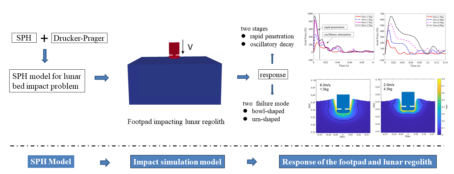
Landing spacecraft experience significant impact forces during landing, resulting in large deformation and failure in the soil surface, which severely affects landing safety and stability. This paper establishes a smoothed particle hydrodynamics (SPH) model based on the theory of soil elastoplastic constitutive relations to describe the process of a lander’s footpad impacting lunar regolith vertically. The model can provide engineering indices such as impact load and penetration depth, and illustrate the large deformation and crater characteristics of the regolith. A detailed analysis of the response of the footpad and lunar regolith during landing reveals that the process can be broadly divided into two stages of rapid penetration and oscillatory attenuation. Furthermore, there are significant similarities in the landing process under different landing velocities and footpad masses. The research investigates the large deformation and crater characteristics of the lunar regolith bed. The results demonstrate two failure modes in the regolith. Under the impact of a footpad with a smaller mass, the final failure surface of the regolith exhibits a bowl-shaped profile with a uniformly open mouth. In contrast, under the impact of a footpad with a larger mass, the final failure surface of the regolith presents an urn-shaped profile with a large abdomen and a small opening. However, the impact craters in both scenarios show a bowl-like distribution. In cases of high-velocity impacts, the impact crater exhibits obvious blocky spalling on its sides. The SPH model developed in this study can be applied to predict the large deformation and failure response of lunar soil under the impact of rigid structures as well as the impact load and penetration depth. It effectively predicts the dynamic response of the landing process, which is expected to provide a reference for engineering design.Graphic Abstract
Keywords
Landing spacecraft encounter substantial impact forces during touchdown, posing a significant threat to the safety of onboard scientific instruments [1]. As such, ensuring a safe and stable landing is paramount for the success of lunar exploration mission [2]. During the landing process, the lander’s footpads directly interact with the lunar regolith. The dynamic behavior of this footpad-regolith interaction, such as impact load, penetration depth, and soil structure deformation directly influence landing safety and stability.
Researchers both domestically and internationally have conducted experimental, theoretical, and numerical simulation studies on this issue. In terms of experimental research, Aravind et al. [3] designed a footpad based on the Apollo 11 lunar module and conducted stability testing experiments. The results indicate that the newly designed footpad exhibits good stability under steep gradient conditions. Huang et al. [4] designed a vertical impact device to study the effects of soil type and density, impact height, and footpad diameter on impact depth, peak impact force, and peak acceleration, and they also established a model for the peak impact force of the footpad. Sutoh et al. [5] developed a drop test rig that allows for repeated drop tests in a vacuum chamber to test the impact of footpad shape, ground conditions, and gravity on landing. Liu et al. [6] conducted vertical landing impact tests using a self-developed landing impact test system with a hemispherical footpad. They investigated the influence of landing mass and impact velocity on the efficiency of mechanical energy dissipation and impact force during landing. In addition, Sutoh et al. [5] developed a model for the motion characteristics of a footpad in a vacuum based on drag theory, further investigating the relationship between force and penetration depth. Hou et al. [7] established a theoretical model for the interaction between a lander and the lunar regolith by dividing the landing impact process into loading and unloading phases based on actual landing scenarios. During the loading phase, they employed the NASA (National Aeronautics and Space Administration)-proposed pressure-settlement theory, treating the lunar regolith as a spring with variable stiffness that changes with depth. The unloading phase was modeled based on the strong compaction process in geomechanics. Lin et al. [8] developed a two-dimensional theoretical model for soft landing and investigated the influence of various factors, including initial horizontal velocity, pitch angle, and lunar slope inclination, on landing dynamics. Wu et al. [9] constructed a theoretical model of foot pad impact on lunar regolith based on the theory of geomechanics. The results were compared with discrete element method simulations, showing an error within 15%. Wang et al. [10] developed a novel three-dimensional soft-landing dynamics model for a legged lander, taking into account the damping characteristics of each landing leg during motion, the contact characteristics between the footpad and the ground, and the friction characteristics between structures. They validated the effectiveness of the model by comparing the results with those obtained from an MSC Adams (MSC. Software: Automatic Dynamic Analysis of Mechanical Systems) simulation model.
Numerical simulation has emerged as another critical approach for this issue, gaining increasing prominence. The coupled interaction between the footpad and lunar regolith involves complex phenomena such as the interaction between structures and soil, as well as large deformation of the soil structure, posing significant challenges for numerical simulations. Nevertheless, it remains a vital method for studying lander impact during landing. Commonly employed methods include rigid body dynamics, finite element analysis, and discrete element methods. Nohmi et al. [11] utilized the rigid body dynamics software ADAMS (Automatic Dynamic Analysis of Mechanical Systems) to simulate the landing process, studying the influence of lander orientation, tilt angle, and friction on landing. Chen et al. [12] simplified the lander design and constructed a finite element model (FEM) of the landing system to investigate the impact of flexible deformation on landing impact performance. Huang et al. [13] simplified the lander to an impact cylinder at a 1/6 scale and developed a 3D finite element model for the footpad impact on lunar regolith. The Mohr-Coulomb constitutive model was used to describe the mechanical properties of the regolith. The model simulated the footpad impact process, analyzing the dynamic response of axial force, velocity, and displacement. Liang et al. [14] introduced a landing impact dynamics analysis method based on nonlinear finite elements to simulate the landing process. The simulation provided information on load, acceleration, and energy dissipation of the shock absorber. The ground model employed the Drucker-Prager constitutive model. Hou et al. [7] established a discrete element model (DEM) for the interaction between the lander and lunar regolith, exploring the impact of landing velocity, lander mass, and terrain slope on the landing process. Ji et al. [15] proposed a coupled DEM-FEM-MBD (Multibody Dynamics) algorithm and simulated the landing process, discussing the effects of lander mass, landing velocity, and landing attitude on landing safety. The ground was described using a discrete element model.
The Smoothed Particle Hydrodynamics (SPH) method, as a mesh-free method, exhibits unique advantages in handling large deformations, free surfaces, and complex boundary conditions. Therefore, it has been widely applied and developed in recent years. Researchers have extensively studied and refined the SPH model to simulate the motion and failure of materials such as metals, concrete, soil, rubber, and ice, applying it to impact problems. The SPH method has found widespread application in the study of diverse impact phenomena, including solid-structure interactions, fluid-structure interactions, explosive impact events and impact on Granular Materials. Khayyer et al. [16] considered four numerical aspects or shortcomings of the traditional SPH model and proposed a method to improve the accuracy and stability of the updated Lagrangian SPH in structural modeling. Lee et al. [17] proposed a novel Arbitrary Lagrangian-Eulerian SPH framework and evaluated the algorithm’s conservation, stability, and robustness, the results of which has significant potential for enhancing the resolution of pressure and stress fields in critical plastic zones. Research on solid-structure impact focuses on the deformation and failure of steel plates, concrete, and composite materials under projectile and rockfall impact [18,19]. In the study of fluid-structure interaction problems, Siemann et al. [20] conducted explicit numerical simulations of flexible aircraft ditching using a coupled SPH-FEM method to study the impact loading of water and the deformation of the aircraft fuselage. Wang et al. [21] employed the SPH method to simulate the water entry of elastomers, effectively modeling the impact force, deflection, and stress of the elastomer. Mintu et al. [22] established a full-scale computational fluid dynamics model of sea spray generated by waves using the SPH method, simulating a full-scale medium-sized fishing vessel encountering incoming waves at different forward speeds. More details of fluid-structure interaction with SPH method could be found in two recent reviews [23,24]. For explosive impact problems [25,26], the main focus of research is on modeling the damage and failure mechanisms of structures subjected to blast loads. While for granular particle system, in contrast to the aforementioned research, the study of solid impact on granular materials remains less developed, particularly concerning the description of granular flow, deformation, and failure under impact loading [27,28]. However, SPH has been progressively employed in the study of large deformation flow [29–33] and multi-physics coupling [34–37] in granular soil media, demonstrating strong capabilities in addressing problems involving large deformation flow in soil media induced by structural motion. Compared to traditional finite element methods, the SPH model avoids complex mesh distortion issues. In contrast to discrete element methods, SPH models are based on continuum theory for discretization, enabling better representation of large-scale engineering problems without dealing with the complex coarsening issues encountered in discrete element models.
Lunar exploration missions and related research have revealed that the lunar surface is covered with a granular regolith layer. During a lander’s touchdown, the regolith medium undergoes significant deformation, potentially leading to complex motion, including large deformations and even fluid-like behavior. While current research has achieved notable advancements in describing rigid body motion and structural deformation, the depiction of large deformation and fluid-like behavior in the regolith remains relatively preliminary. However, to date, no reports have documented the application of SPH models to the coupled interaction between lunar regolith and structures. Therefore, this paper attempts to develop an SPH method based on the elastoplastic constitutive model for soil, to simulate the large deformation and failure response of lunar regolith under footpad impact, and to study the characteristics of impact load and penetration depth.
2 Numerical Model and Validation
Smoothed Particle Hydrodynamics (SPH) is a Lagrange meshfree particle method. Its fundamental principle involves representing the problem domain using a set of arbitrarily distributed particles, which are not connected. This eliminates the need for a fixed grid, thus avoiding issues such as mesh distortion that can arise during large deformations.
The governing equations for soil motion are the conservation of mass and the conservation of momentum, expressed in Eqs. (1) and (2).
where
To better capture the behavior of lunar regolith particles during their interaction, a Drucker-Prager elastoplastic constitutive model was incorporated into the SPH model. The stress-strain relationship is given by Eq. (3).
where ‘
The rate of change of the plastic multiplier
Within the Drucker-Prager constitutive model under a non-associated flow rule, the yield function
where
The values of the constants in the Drucker-Prager constitutive model are given by Eqs. (12)–(14).
The core steps in the discretization of equations using the Smoothed Particle Hydrodynamics (SPH) method involve kernel approximation and particle approximation. Kernel approximation refers to expressing field functions in integral form. Particle approximation, on the other hand, involves approximating the integral of a field function and its derivatives using a weighted sum of the values of state variables possessed by particles within a local region, known as the support domain.
The governing equations for soil, following SPH discretization, are expressed by Eqs. (15) and (16).
where
where
where
To compute
where
where
The discrete form of the constitutive equation is given by Eq. (21).
The expression for
The expressions for the total strain rate tensor
In the SPH model, rigid bodies are also represented by particles with physical properties. The force acting on a specific particle of a rigid body is calculated by weighting the contributions from all fluid particles within its support domain. The force per unit mass
where
The motion of a rigid body can be described using the fundamental equations of rigid body dynamics:
where
The SPH model, based on the elastoplastic constitutive law of soil, has been successfully applied to various problems, including large-scale landslides [39], and landslide surge waves [40]. This paper aims to extend this model to study the interaction between lunar regolith and the landing process. But it is a large displacement and small deformation model, which may suffer problems of variational inconsistency as in finite deformation in structural problems [41,42]. In SPH community of soil deformation problem, it should be paid more attention in future.
In this section, we simulated a similar case where a rigid body impacts a granular bed, and compared the results with experimental and discrete element method simulations [43]. Fig. 1 shows a schematic diagram of the model for a hemispherical rigid body impacting granular material. The hemispherical rigid body impacts the granular bed with an initial velocity. The radius of the hemisphere is 20 mm, its mass is 2 kg, and its initial velocity is 4 m/s. The granular bed has dimensions of 0.4 m × 0.4 m × 0.2 m. The computational parameters are listed in Table 1. The simulation results are compared with DEM simulations and experimental results, as shown in Fig. 2. The results demonstrate that the model can effectively simulate the dynamic behavior of a rigid body impacting a granular bed.

Figure 1: Impact model for validation (Blue: granular bed; Red: Rigid hemisphere)
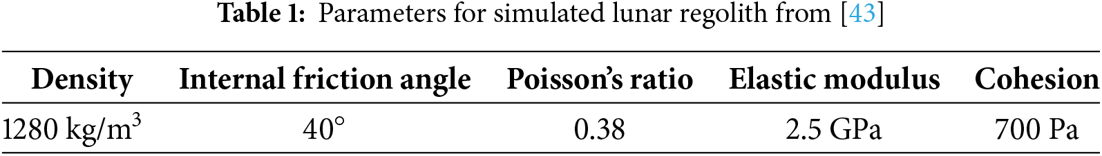

Figure 2: Comparison of simulation results with experimental and DEM results (a) Time history of penetration depth; (b) Time history of velocity
The gravitational acceleration on the moon is approximately 1/6 that of on the earth. Zhang et al. [44] compared the test results of a 1/6 scale model under earth’s gravity with those of a prototype under simulated lunar gravity, and found significant similarities. Therefore, in this study, the footpad model is simplified to 1/6 scale and the gravitational environment is set to earth’s gravity. And The footpad is simplified to an impact cylinder consisting of a footpad and a counterweight [13]. The simplified model is referred to as the footpad hereinafter, and its simplified schematic is shown in Fig. 3, where the simplified footpad diameter is 8.3 cm.

Figure 3: Simplified model
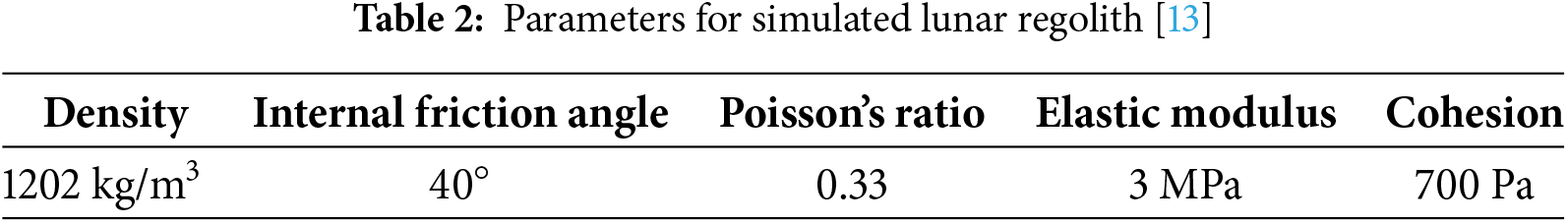
Due to the difficulty in obtaining large quantities of lunar regolith, simulated lunar regolith with similar composition and properties is commonly used in research [45]. In this study, TJ-1 simulated lunar regolith [46] was chosen, which is made from red volcanic ash in Jingyu County, Jilin Province. This material has low production costs and exhibits a high degree of similarity to real lunar regolith. In the following text, it will be referred to as lunar regolith. Researchers have already conducted laboratory tests on the relevant parameters of TJ-1 [13] as listed in Table 2.
The footpad is treated as a rigid body, and a 3D SPH model is established to simulate the impact of the footpad onto the simulated lunar regolith, as illustrated in Fig. 4. The particle spacing dp is set to 0.002 m. Initially, the footpad is located 10 mm above the surface of the regolith, which then descends with a given initial velocity and interacts with the regolith below.

Figure 4: 3D model of footpad impacting simulated lunar regolith (Blue: simulated lunar regolith, Red: footpad)
To mitigate the influence of boundary effects on the simulation, a convergence analysis was conducted on the dependence of sample size and initial particle spacing dp. Keeping the pad’s mass and initial velocity constant, the time history of the pad penetration depth into the lunar regolith for different soil sizes are shown in Fig. 5a. As observed in the figure, the penetration depth time history curves are nearly identical when the soil size is 0.6 m × 0.6 m × 0.35 m and 0.7 m × 0.7 m × 0.35 m, indicating that boundary effects are essentially eliminated for this granular bed size. Maintaining the soil size at 0.6 m × 0.6 m × 0.35 m, the time history curves of the pad penetration depth into the lunar regolith for different initial particle spacings are shown in Fig. 5b. The figure shows that the penetration depth time history curves are nearly identical when the initial particle spacing is 0.002 and 0.001 m. Therefore, in subsequent simulations, the initial particle spacing is set to 0.002 m, and the soil size is set to 0.6 m × 0.6 m × 0.35 m, resulting in a total of 29,061,881 SPH particles used in the simulation.

Figure 5: Time histories of penetration depth (a) Various soil dimensions; (b) Various dps
The physical time for a typical single simulation case is 0.15 s, and the entire simulation time is approximately 4 h using an RTX A6000 with 48 GB of global memory and 84 multiprocessors with a clock rate of 1.80 GHz.
To validate the feasibility of the SPH model, the simulated results are compared with those from a theoretical model. In the theoretical model, the landing impact process is divided into two stages: loading and unloading [7]. The loading stage starts from the initial interaction and ends when the footpad velocity first drops to zero. The unloading stage follows. During the loading stage, the Bekker bearing capacity model [47] is adopted, treating the lunar regolith as a spring with varying stiffness. The effects of plasticity and viscosity of the lunar regolith are ignored. During the unloading stage, the influence of gravity is neglected.
The landing processes under different working conditions were simulated, and the maximum axial force acting on the footpad and the maximum penetration depth into the lunar regolith were selected as comparison parameters. To minimize landing risks, landers are designed to decelerate during their descent, achieving a soft landing at a lower velocity. Therefore, relevant experiments and simulations typically employ smaller landing velocities for research purposes, generally ranging from 1 to 6 m/s. Currently, published landers masses fall between 600 and 1700 kg, so their masses are often scaled down to 1 to 8 kg for experimental and simulations [7,13]. Therefore, the following test conditions were established, as shown in Table 3. The comparison results are presented in Fig. 6. It can be observed from these figures that the errors between the simulation results and the empirical model are within 15%, indicating that the SPH model can effectively calculate such problems.
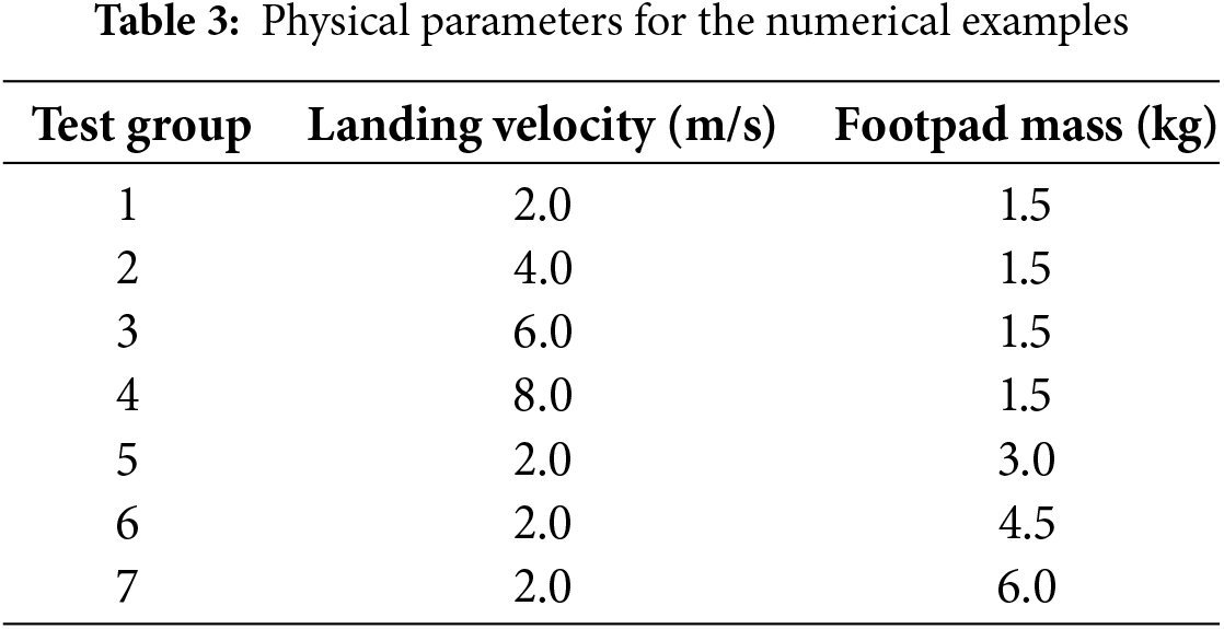
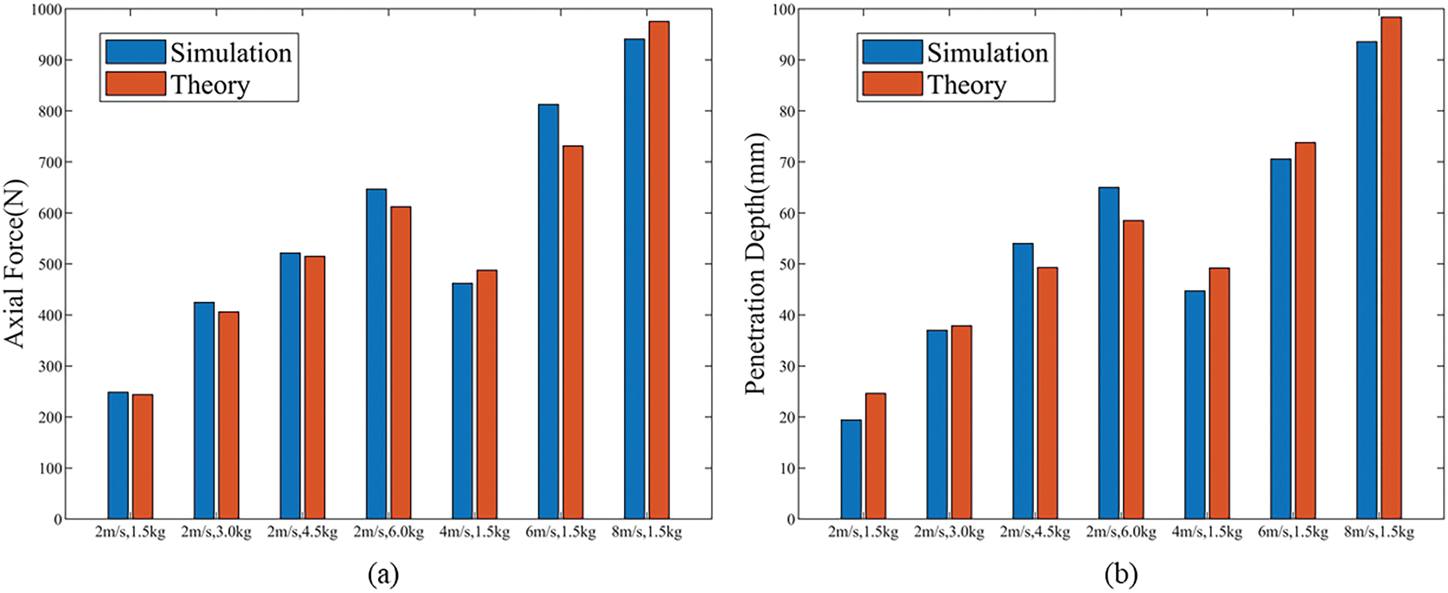
Figure 6: Comparison of simulation results with theoretical [7] calculation results (a) Maximum axial force; (b) Maximum penetration depth
It is important to note that in all the cases considered in this study, after calculation, the maximum order of inertia number is 10−3. The inertial effects of the particulate medium are therefore negligible [48,49], making the selection of the DP criterion for quasi-static conditions appropriate for this study.
Landing velocity and footpad mass are significant factors influencing the interaction between the footpad and lunar regolith. The following analysis examines the impact of these factors, as well as the response of the footpad and lunar regolith during the interaction.
3.1 Impact of Landing Velocity on the Landing Process
The stress development in lunar regolith exhibits similar patterns under different conditions. Fig. 7 shows the stress distribution under the working conditions of v = 4 m/s and m = 1.5 kg. The results show that the stress concentrates primarily at the bottom of the footpad. Upon initial contact, the stress value is relatively high. Subsequently, the stress gradually decreases, and the affected area gradually expands. Finally, the stress dissipates, the affected area decreases, and disappears to only self-weight finally.

Figure 7: Stress distribution at different times
In the SPH method, the computational domain is discretized into a number of particles. Therefore, the axial force acting on the footpad can be calculated by first obtaining the force
The initial lowest point of the footpad is
Fig. 8 shows the time histories of axial force and penetration depth for different landing velocities, respectively. The dynamic response curves of the footpad are similar for different landing velocities, but the peak axial force and maximum penetration depth differ.
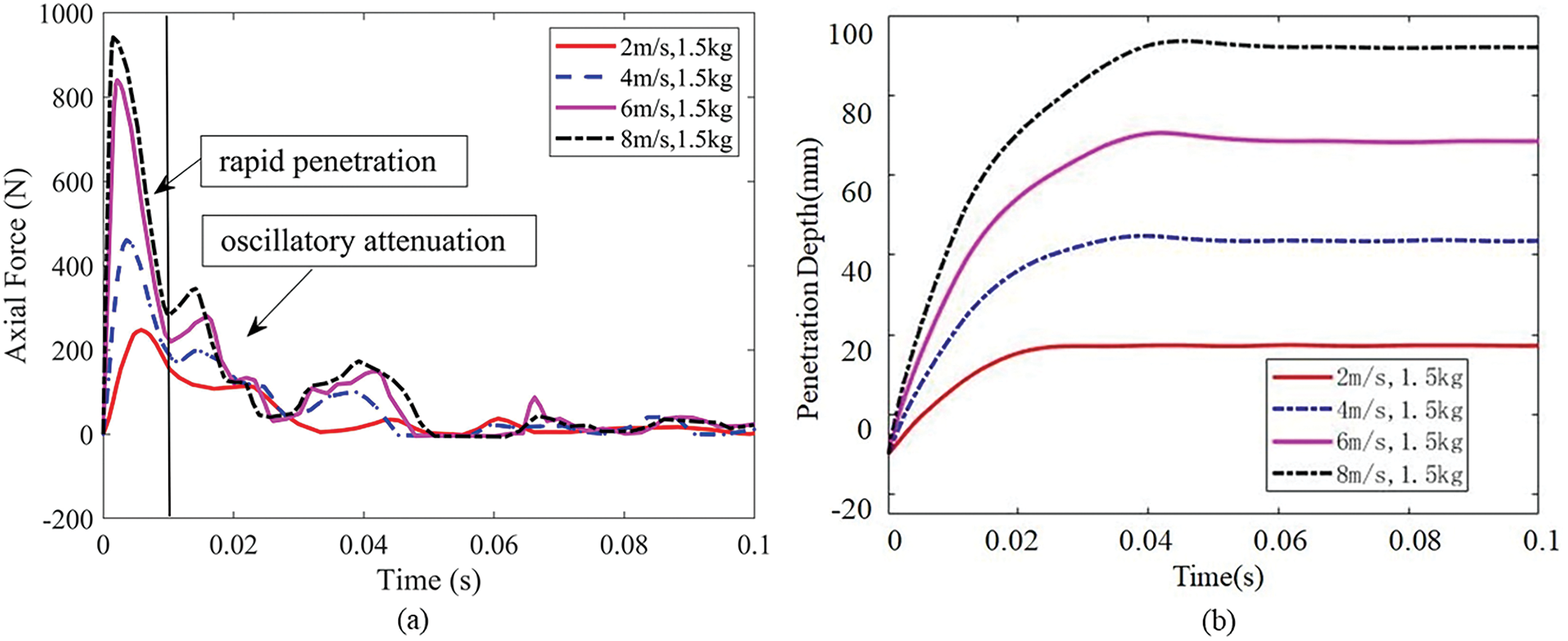
Figure 8: Axial force and penetration depth time histories for different landing velocities (a) Axial force time histories; (b) Penetration depth time histories
As shown in Fig. 8a, the interaction process can be divided into two stages as rapid penetration and oscillatory decay. During the rapid penetration stage (0–0.01 s), the axial force experienced by the footpad increases rapidly, reaching a peak value before quickly decreasing. Furthermore, the higher the landing velocity, the greater the rate of change of the axial force during this stage. Simultaneously, the regolith is compacted and yields, causing subsidence, allowing the footpad to rapidly penetrate into the lunar regolith. After 0.01 s, the oscillatory decay stage begins. During this stage, the area of the regolith affected by the subsidence expands, and the lunar regolith is further compacted. Therefore, the axial force acting on the footpad experiences a renewed peak. Before the velocity drops to zero, the footpad further squeezes the plastic failure zone below at a slower speed, resulting in a renewed increase in axial force, and then the elastic energy of the plastic zone is released, causing a rapid decrease in axial force. During this process, the penetration velocity of the footpad into the lunar regolith significantly decreases until the penetration depth reaches a peak value. Subsequently, due to the partial recovery of regolith deformation, the footpad rebounds slightly and then stabilize.
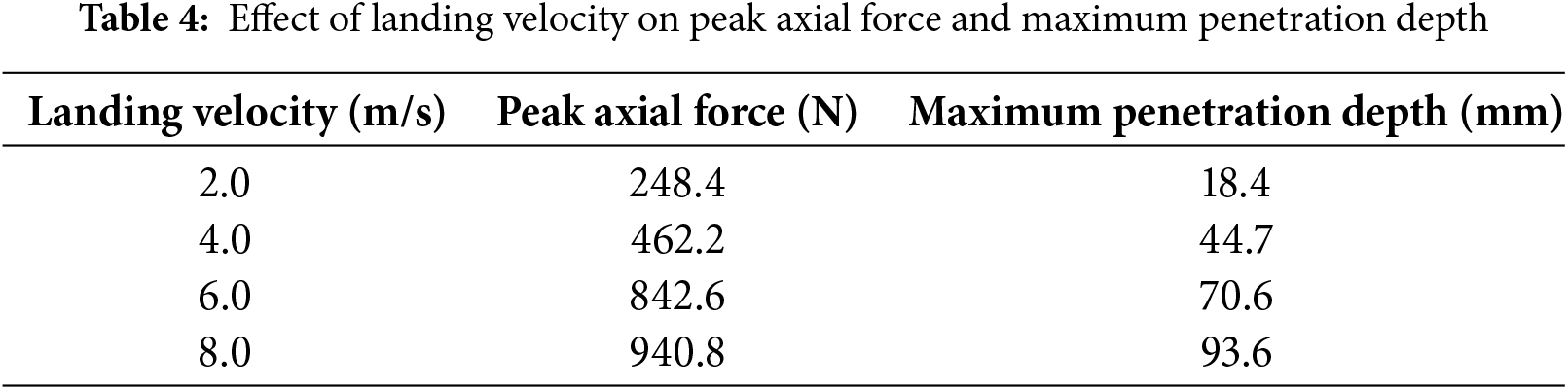
Fig. 8b shows that the footpad’s penetration velocity into the lunar regolith decreases significantly after the rapid penetration stage. This is because the footpad loses a significant amount of kinetic energy during the rapid penetration stage, exceeding 60% of its initial kinetic energy. Table 4 shows the relationship between peak axial force and maximum penetration depth and landing velocity. Both peak axial force and maximum penetration depth increase with increasing landing velocity.
3.2 Impact of Footpad Mass on the Landing Process
Fig. 9 shows the time histories of axial force and penetration depth for different footpad masses, respectively. The dynamic response curves of the footpad are similar for different masses, but the peak axial force, maximum penetration depth, and impact time differ significantly. As the footpad mass increases, the peak axial force and maximum penetration depth also increase, and the interaction time lengthens accordingly.
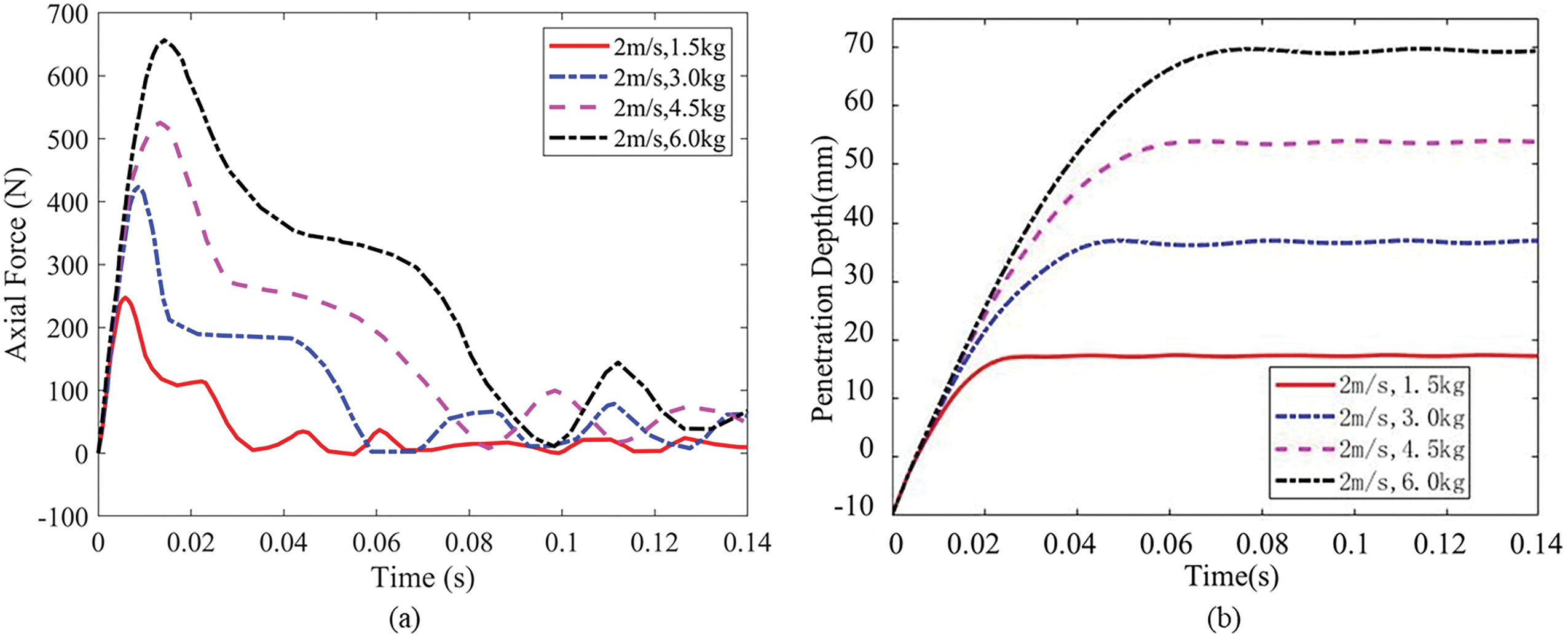
Figure 9: Axial force and penetration depth time histories for different footpad masses (a) Axial force time histories; (b) Penetration depth time histories
Initially, the axial force and penetration depth experienced by footpads with different initial masses are approximately equal. This is because the footpads have the same initial velocity, resulting in similar displacements. Consequently, the lunar regolith undergoes similar compression and deformation, leading to similar axial forces acting on the footpads. Subsequently, due to the different masses of the footpads, their axial accelerations differ when subjected to the same axial force. This ultimately leads to variations in the dynamic response across different scenarios. Table 5 shows the relationship between peak axial force, maximum penetration depth, and footpad mass.
3.3 Lunar Regolith Response and Crater Characteristics
During the interaction between the footpad and the lunar regolith, significant deformation occurs in the regolith, ultimately leading to the formation of an impact crater. The formation process and characteristics of this impact crater are crucial responses to the interaction between the footpad and the regolith, and constitute a significant concern for engineering design.
As shown in Fig. 10, two modes of failures were found for the failure surface for all the numerical cases, which is termed as bowl-shaped failure mode and urn-shape mode. Here a typical value of 10% accumulated plastic strain contour surface is chosen to characterize the localization in the large deformation process. Therefore, two scenarios were selected for analysis: a landing velocity of 4 m/s with a footpad mass of 1.5 kg and a landing velocity of 2 m/s with a footpad mass of 6 kg. These scenarios were chosen to investigate the regolith’s response during landing. Based on the axial force response during landing, six characteristic time points were selected. These time points are illustrated in Figs. 11 and 12.

Figure 10: The final failure surface of the regolith for difference mass and impact speed

Figure 11: Axial force time history for 4 m/s, 1.5 kg condition

Figure 12: Axial force time history for 2 m/s, 6 kg condition
Fig. 13 shows the distribution of accumulated plastic strain in the lunar regolith at characteristic moments during landing with a velocity of 4 m/s and a footpad mass of 1.5 kg. To better visualize the large deformation failure process and characteristics of the regolith bed, we consistently select an accumulated plastic strain of 10% as the failure surface of the soil structure for all times, as indicated by the black contour lines in Fig. 13. As shown in Fig. 13a,b, during the rapid penetration stage, the accumulated plastic strain at the edge of the footpad is relatively large. Initially, the regolith does not exhibit significant plastic failure. The downward motion of the footpad compresses the regolith, causing the axial force to increase rapidly. As the footpad continues to move downward, the regolith at the footpad’s edge undergoes significant shear failure, resulting in decreased soil resistance and a reduction in axial force. However, a completely continuous failure surface is not yet formed.
Figure 13: Distribution of accumulated plastic strain for case with 4 m/s of impact speed and 1.5 kg for mass
Upon entering the oscillatory decay stage, as the footpad continues downward, it compresses the surrounding regolith, expanding the affected area. The plastic failure zone grows, as depicted in Fig. 13c, leading to increased regolith resistance and a small peak in axial force. The distribution of the failure surface at this time exhibits an elliptical shape with sharp corners. After reaching a certain thickness, the plastic failure zone maintains a relatively stable thickness, as illustrated in Fig. 13d. This thickness no longer increases, and the regolith surrounding the plastic failure zone becomes more compact under pressure as the footpad continues to move downward. Subsequently, the regolith below the plastic failure zone becomes compacted, leading to a smaller displacement in the area beneath the plastic zone compared to the area above it. The downward motion of the footpad causes compression of the plastic failure zone, as shown in Fig. 13e, resulting in another increase in axial force. Finally, the elastic energy stored in the plastic zone is released, causing the axial force to decrease rapidly and stabilize. The distribution of the plastic strain remains constant, and the final failure surface resembles a uniformly open bowl shape, which is termed as bowl-shaped failure mode.
Fig. 14 displays the distribution of accumulated plastic strain in the lunar regolith at characteristic moments during landing with a velocity of 2 m/s and a footpad mass of 6 kg. The black lines in the figure represent the 10% accumulated plastic strain contour lines. As shown in Fig. 14a, plastic failure occurs in the lunar regolith shortly after the footpad interacts with it. As the footpad moves downward, the plastic failure zone expands, and the axial force increases accordingly. A complete plastic failure zone is formed during the rapid penetration stage. After further development, the plastic failure zone reaches a relatively stable state, and its thickness no longer increases, as illustrated in Fig. 14b.
Figure 14: Distribution of accumulated plastic strain for case with 2 m/s for impact speed and 6 kg for mass
Upon entering the oscillatory decay stage, because of the regolith below the plastic failure zone is compacted. When subjected to stress, the displacement of the regolith beneath the plastic failure zone is smaller than that above it. Therefore, the footpad’s movement compresses the plastic failure zone, as shown in Fig. 14c. At this point, the axial force remains relatively stable, and the failure surface resembles a uniformly open bowl shape. Finally, the accumulated elastic energy stored in the plastic zone is released, causing the axial force to decrease rapidly and then fluctuate around the magnitude of the footpad’s weight. The surface failure zone no longer increases in size, but the internal failure zone continues to expand, as shown in Fig. 14d–f. Ultimately, the failure surface exhibits a characteristic urn shape with a larger abdomen and a smaller opening, which is termed as urn-shaped failure mode.
The size and shape of the impact crater formed by a lander during touchdown contain a wealth of information. The morphology of the crater is closely related to the strength, density, and particle size distribution of the lunar regolith, and also reflects the landing performance of the lander. Moreover, the condition of the crater is crucial for ensuring the safety and stability of the landing. Huang et al. [13] experimentally demonstrated that impact craters formed by footpad impacts under various conditions exhibit similar morphologies. Our simulation finds similar bowl-shaped impact craters as in experiment of Huang. Fig. 15 shows the final morphology of the impact craters formed at different landing velocities. The craters exhibit similar shapes at different velocities, featuring a flat bottom with a raised surface. The impact crater depth and width increase with increasing landing velocity, with a greater impact on depth. As the velocity increases, the crater walls become steeper.
Figure 15: Crater morphology at different landing velocities
At higher velocities, the impact craters become unstable, there is regolith detaching from the crater walls and falling into the crater, as illustrated in Fig. 16. This phenomenon intensifies with increasing velocity. At 4 m/s, only a small number of particles detach, while at 6 m/s, larger regolith blocks fall. At 8 m/s, a significant number of particles and regolith blocks detach from the crater walls. This phenomenon poses a threat to the landing safety and stability of the lander, as well as to subsequent exploration activities. Further analysis of its impact is warranted in future research.

Figure 16: Crater wall morphology at different landing velocities
The effect of footpad mass on the impact crater is shown in Fig. 17. As the footpad mass increases, the impact crater depth noticeably increases, but the crater width does not always increase proportionally. When the footpad mass is greater than 3 kg, the crater width does not change significantly with increasing mass. Moreover, variations in mass do not affect the stability of the impact crater. The final morphologies of impact craters formed at different landing velocities and footpad masses are similar. The craters exhibit a bowl-shaped distribution.

Figure 17: Crater morphology at different footpad masses
This paper established a 3D SPH model to simulate the interaction between a landing footpad and simulated lunar regolith. The effects of landing velocity and mass on the landing process are investigated, and the dynamic responses of both the footpad and the regolith during the interaction are analyzed. The following conclusions are drawn:
1) A 3D SPH model of the interaction between a landing footpad and lunar regolith has been developed by extending a former SPH model of large deformation of granular system, which can predict engineering indicators such as axial force and penetration depth. Compared to typical empirical models, this model can additionally capture the large-scale deformation and failure of the regolith bed, as well as the crater response.
2) The interaction between the footpad and the lunar regolith can be broadly divided into two stages: rapid penetration and oscillatory decay. Despite variations in landing velocity and footpad mass, the landing process exhibits similarities. The maximum penetration depth and peak axial force exhibit a positive correlation with both landing velocity and footpad mass.
3) Under the impact of a lighter footpad, the lunar regolith bed exhibits a bowl-shaped failure mode with a uniformly open mouth for the failure surface. With a heavier footpad, the regolith bed suffers an urn-shaped failure mode, characterized by a larger abdomen and a smaller opening for the failure surface. In both cases, the resulting impact craters display a bowl-shaped distribution. At higher velocities, significant blocky spallation is observed on the sides of the craters.
However, this study only analyzes the interaction between a single footpad and the lunar regolith, neglecting the synergistic effect of multiple footpads and the impact of the lander’s attitude changes on the regolith during a real landing. Therefore, the results of this study have a certain gap with the actual landing process and cannot fully reflect the interaction mechanism between the footpad and the lunar regolith in a real scenario. Future research will further consider the interaction of multiple footpads and the influence of lander attitude changes on the lunar regolith, to simulate the lunar landing process more accurately. As for the SPH model, deformation of the structure and its coupling with the lunar bed granular system also needs to be studied.
Acknowledgment: The authors are grateful to the anonymous reviewers for improving this article.
Funding Statement: This research was funded by the National Natural Science Foundation of China (Nos. 12172057 and 12032005).
Author Contributions: The authors confirm contribution to the paper as follows: study conception and design: Wanqing Yuan, Xiaoliang Wang; data collection: Wanqing Yuan, Can Huang; analysis and interpretation of results: Wanqing Yuan, Xiaoliang Wang; draft manuscript preparation: Wanqing Yuan; management and coordination: Huiying Xie, Qingquan Liu. Funding: Xiaoliang Wang, Qingquan Liu. All authors reviewed the results and approved the final version of the manuscript.
Availability of Data and Materials: The data that support the findings of this study are available from the corresponding author upon reasonable request.
Ethics Approval: None.
Conflicts of Interest: The authors declare no conflicts of interest to report regarding the present study.
References
1. Doiron HH, Zupp GA, Aiaa A. Apollo lunar module landing dynamics. In: AIAA/ASME/ASCE/AHS/ASC 41st Structures, Structural Dynamics, and Materials Conference; 2000; Atlanta, GA, USA. [Google Scholar]
2. Liu Y, Song S, Li M, Wang C. Landing stability analysis for lunar landers using computer simulation experiments. Int J Adv Robot Syst. 2017;14(6). doi:10.1177/1729881417748441. [Google Scholar] [CrossRef]
3. Aravind G, Vishnu S, Amarnath KV, Hithesh U, Harikrishnan P, Sreedharan P, et al. Design, analysis and stability testing of lunar lander for soft-landing. In: International Conference on Advances in Materials and Manufacturing Applications, 2020; Bengaluru, India. [Google Scholar]
4. Huang H, Li JQ, Chen BC, Wu B, Zou M. Experiment of impact performance of space lander footpad. J Jilin Univ (Eng Technol Ed). 2017;47(4):1194–200. [Google Scholar]
5. Sutoh M, Wakabayashi S, Hoshino T. Landing behavior analysis of lunar probe based on drop tests and RFT in a vacuum. IEEE Robot Autom Let. 2018;3(1):360–6. doi:10.1109/LRA.2017.2749680. [Google Scholar] [CrossRef]
6. Liu H, Wang YB, Liang SM, Wu SQ. Vertical impact test study of soft landing of lander. Sci Technol Eng. 2020;20(2):848–53. [Google Scholar]
7. Hou XY, Xue PP, Wang YB, Cao P, Tang TF. Theoretical and discrete element simulation studies of aircraft landing impact. J Braz Soc Mech Sci. 2018;40(3):1–16. doi:10.1007/s40430-018-0983-1. [Google Scholar] [CrossRef]
8. Lin Q, Ren J. Investigation on the horizontal landing velocity and pitch angle impact on the soft-landing dynamic characteristics. Int J Aerosp Eng. 2022;1(1):3277581. [Google Scholar]
9. Wu SQ, Wang YB, Hou XY, Xue PP, Long L. Research on theoretical model of vertical impact of foot pad on lunar soil. Manned Spaceflight. 2020;26(2):135–41. [Google Scholar]
10. Wang ZY, Chen CZ, Chen JB, Zheng G. 3D soft-landing dynamic theoretical model of legged lander: modeling and analysis. Aerospace. 2023;10(9):811. [Google Scholar]
11. Nohmi M, Miyahara A. Modeling for lunar lander by mechanical dynamics software. In: AIAA Modeling and Simulation Technologies Conference and Exhibit, 2005; San Francisco, CA, USA. [Google Scholar]
12. Chen JB, Nie H, Bo W. Research on touchdown performance of soft-landing system with flexible body. J Vibroeng. 2013;15(3):1255–62. [Google Scholar]
13. Huang B, Jiang ZJ, Lin P, Ling DS. Research on impact process of lander footpad against simulant lunar soils. Shock Vib. 2015;2015(1):1–24. [Google Scholar]
14. Liang DP, Wang G, Zhang P. Landing dynamic analysis for landing leg of lunar lander using nonlinear finite element method. Adv Astronaut Sci Technol. 2022;5(3):235–40. doi:10.1007/s42423-022-00120-w. [Google Scholar] [CrossRef]
15. Ji SY, Liang SM. DEM-FEM-MBD coupling analysis of landing process of lunar lander considering landing mode and buffering mechanism. Adv Space Res. 2021;68(3):1627–43. doi:10.1016/j.asr.2021.03.034. [Google Scholar] [CrossRef]
16. Khayyer A, Shimizu Y, Lee CH, Gil A, Gotoh H, Bonet J. An improved updated Lagrangian SPH method for structural modelling. Comput Part Mech. 2024;11(3):1055–86. doi:10.1007/s40571-023-00673-z. [Google Scholar] [CrossRef]
17. Lee CH, Gil AJ, de Campos PRR, Bonet J, Jaugielavicius T, Joshi S, et al. A novel Arbitrary Lagrangian Eulerian Smooth Particle Hydrodynamics algorithm for nonlinear solid dynamics. Comput Methods Appl Mech Engrg. 2024;427:1055–86. doi:10.1016/j.cma.2024.117055. [Google Scholar] [CrossRef]
18. Ji XY, Li YC, Huang XC, Chen G. Coupled FE-SPH simulation of truncated-conical projectiles penetrating steel sheets. In: 7th International Conference on Shock and Impact Loans on Structures; 2007; Beijing, China. [Google Scholar]
19. Mei XF, Wang T, Su T, Zhu D, Li BX, Wu JL. Shape effect of rockfall impacting sandy soil cushion layer-reinforced reinforced concrete slab composite structure. Mater Sci Medziagotyra. 2024;30(3):404–13. doi:10.5755/j02.ms.36216. [Google Scholar] [CrossRef]
20. Siemann MH, Schwinn DB, Scherer J, Kohlgrueber D. Advances in numerical ditching simulation of flexible aircraft models. Int J Crashworthiness. 2018;23(2):236–51. doi:10.1080/13588265.2017.1359462. [Google Scholar] [CrossRef]
21. Wang L, Xu F, Yang Y. SPH scheme for simulating the water entry of an elastomer. Ocean Eng. 2019;178:233–45. doi:10.1016/j.oceaneng.2019.02.072. [Google Scholar] [CrossRef]
22. Mintu S, Molyneux D, Colbourne B. Full-scale SPH simulations of ship-wave impact generated sea spray. Ocean Eng. 2021;241:110077. doi:10.1016/j.oceaneng.2021.110077. [Google Scholar] [CrossRef]
23. Liu MB, Zhang ZL. Smoothed particle hydrodynamics (SPH) for modeling fluid-structure interactions. Sci China-Phys Mech Astron. 2019;62(8):984701. doi:10.1007/s11433-018-9357-0. [Google Scholar] [CrossRef]
24. Zhang AM, Sun PN, Ming FR, Colagrossi A. Smoothed particle hydrodynamics and its applications in fluid-structure interactions. J. Hydrodyn. 2017;29(2):187–216. doi:10.1016/S1001-6058(16)60730-8. [Google Scholar] [CrossRef]
25. Chen JY, Peng C, Lien FS, Yee E, Zhao XH. Simulations for the explosion in a water-filled tube including cavitation using the SPH method. Comput Part Mech. 2019;6(4):515–27. doi:10.1007/s40571-019-00230-7. [Google Scholar] [CrossRef]
26. Azar AB, Sari A. Damage identification of masonry arch bridge under blast loading using smoothed particle hydrodynamics (SPH) method. Struct Eng Mech. 2024;91(1):103–21. [Google Scholar]
27. Luo J, Xiao JC, Ma KJ, Mao JY, Wang QY. Buffering capacity of various types soil under rockfall impact load. J Disaster Prev Mitig Eng. 2019;39(1):164–70. [Google Scholar]
28. Luo J, Xiao JC, Ma KJ, Mao JY. SPH-FEM coupled method for analyzing a hemispherical shell impact soil. J Vib Shock. 2017;36(17):195–9. [Google Scholar]
29. Bui HH, Fukagawa R, Sako K, Wells JC. Slope stability analysis and discontinuous slope failure simulation by elasto-plastic smoothed particle hydrodynamics (SPH). Geotechnique. 2011;61(7):565–74. doi:10.1680/geot.9.P.046. [Google Scholar] [CrossRef]
30. Peng C, Li S, Wu W, An HC, Chen XQ, Ouyang CJ, et al. On three-dimensional SPH modelling of large-scale landslides. Can Geotech J. 2022;59(1):24–39. doi:10.1139/cgj-2020-0774. [Google Scholar] [CrossRef]
31. Zhang WT, Shi CQ, An Y, Yang SH, Liu QQ. Viscous elastoplastic SPH model for long-distance high-speed landslide. Int J Comp Meth-Sing. 2019;16(2):1846011. doi:10.1142/S0219876218460118. [Google Scholar] [CrossRef]
32. Hu M, Liu MB, Xie MW, Liu GR. Three-dimensional run-out analysis and prediction of flow-like landslides using smoothed particle hydrodynamics. Environ Earth Sci. 2015;73(4):1629–40. doi:10.1007/s12665-014-3513-1. [Google Scholar] [CrossRef]
33. He X, Liang D, Bolton MD. Run-out of cut-slope landslides: mesh-free simulations. Geotechnique. 2018;68(1):50–63. doi:10.1680/jgeot.16.P.221. [Google Scholar] [CrossRef]
34. Ren B, He M, Li YB, Dong P. Application of smoothed particle hydrodynamics for modeling the wave-moored floating breakwater interaction. Appl Ocean Res. 2017;67:277–90. doi:10.1016/j.apor.2017.07.011. [Google Scholar] [CrossRef]
35. Shi CQ, An Y, Wu Q, Liu QQ, Cao ZX. Numerical simulation of landslide-generated waves using a soil-water coupling smoothed particle hydrodynamics model. Adv Water Resour. 2016;92:130–41. doi:10.1016/j.advwatres.2016.04.002. [Google Scholar] [CrossRef]
36. Mahallem A, Roudane M, Krimi A, Gouri SA. Smoothed particle hydrodynamics for modelling landslide-water interaction problems. Landslides. 2022;19(5):1249–63. doi:10.1007/s10346-021-01807-1. [Google Scholar] [CrossRef]
37. Wang XL, Shi CQ, Liu QQ, An Y. Numerical study on near-field characteristics of landslide-generated impulse waves in channel reservoirs. J Hydrol. 2021;595:126012. doi:10.1016/j.jhydrol.2021.126012. [Google Scholar] [CrossRef]
38. Bui HH, Fukagawa R, Sako K, Ohno S. Lagrangian meshfree particles method (SPH) for large deformation and failure flows of geomaterial using elastic-plastic soil constitutive model. Int J Numer Anal Meth Geomech. 2008;32(12):1537–70. doi:10.1002/nag.688. [Google Scholar] [CrossRef]
39. Huang C, Sun YH, An Y, Shi CQ, Feng C, Liu QQ, et al. Three-dimensional simulations of large-scale long run-out landslides with a GPU-accelerated elasto-plastic SPH model. Eng Anal Bound Elem. 2022;145:132–48. doi:10.1016/j.enganabound.2022.09.018. [Google Scholar] [CrossRef]
40. Huang C, Hu C, An Y, Shi CQ, Feng C, Wang HN, et al. Numerical simulation of the large-scale Huangtian (China) landslide-generated impulse waves by a GPU-accelerated three-dimensional soil-water coupled SPH model. Water Resour Res. 2023;59(6):e2022WR034157. doi:10.1029/2022WR034157. [Google Scholar] [CrossRef]
41. Lee CH, Gil AJ, Hassan OI, Bonet J, Kulasegaram S. A variationally consistent streamline upwind Petrov-Galerkin smooth particle hydrodynamics algorithm for large strain solid dynamics. Comput Methods Appl Mech Eng. 2017;318:514–36. doi:10.1016/j.cma.2017.02.002. [Google Scholar] [CrossRef]
42. Khayyer A, Shimizu Y, Gotoh H, Hattori S. A 3D SPH-based entirely Lagrangian meshfree hydroelastic FSI solver for anisotropic composite structures. Appl Math Model. 2022;112:560–613. doi:10.1016/j.apm.2022.07.031. [Google Scholar] [CrossRef]
43. Liang S, Feng YT, Zhao T, Wang Z. On energy transfer and dissipation of intruder impacting granular materials based on discrete element simulations. Powder Technol. 2023;419:118347. doi:10.1016/j.powtec.2023.118347. [Google Scholar] [CrossRef]
44. Zhang ZM, Nie H, Chen JB, Li LC. Investigation on the landing-impact tests of the lunar lander and the key technologies. J Chin Soc Astronaut. 2011;32(2):267–76. [Google Scholar]
45. Sture S. A review of geotechnical properties of lunar regolith simulants. In: 10th Biennial International Conference on Engineering, Construction, and Operations in Challenging Environments and Second NASA/ARO/ASCE Workshop on Granular Materials in Lunar and Martian Exploration, 2006; League City/Houston, TX, USA. [Google Scholar]
46. Jiang MJ, Li LQ, Wang C, Zhang H. A new lunar soil simulant in China. In: Song G, Malla RB, editors. Earth and Space 2010: Engineering, Science, Construction, and Operations in Challenging Environments. Honolulu, Hawaii. Reston: American Society of Civil Engineers; 2010. p. 3617–23. [Google Scholar]
47. Bekker MG. Introduction to terrain-vehicle systems. Ann Arbor, MI, USA: University of Michigan Press; 1969. [Google Scholar]
48. Wang XL, Li G, Liu QQ. An updated critical state model by incorporating inertial effects for granular material in solid-fluid transition regime. Granul Matter. 2022;24:38. doi:10.1007/s10035-021-01202-6. [Google Scholar] [CrossRef]
49. Forterre Y, Pouliquen O. Flows of dense granular media. Annu Rev Fluid Mech. 2008;40:1–24. doi:10.1146/annurev.fluid.40.111406.102142. [Google Scholar] [CrossRef]
Cite This Article
 Copyright © 2025 The Author(s). Published by Tech Science Press.
This work is licensed under a Creative Commons Attribution 4.0 International License , which permits unrestricted use, distribution, and reproduction in any medium, provided the original work is properly cited.
 Downloads
 Citation Tools