
 Submit a Paper
 Propose a Special lssue
 Open Access
ARTICLE

Elastohydrodynamic Lubrication Performance of Curvilinear Cylindrical Gears Based on Finite Element Method
1 School of Intelligent Manufacturing, Panzhihua University, Panzhihua, 617000, China
2 Panzhihua Hangyu New Material Technology Co., Ltd., Panzhihua, 617000, China
3 School of Intelligent Manufacturing, Chengdu Industrial Vocational Technical College, Chengdu, 610218, China
* Corresponding Authors: Xuegang Zhang. Email: ; Xian Wei. Email:
Computer Modeling in Engineering & Sciences 2025, 142(2), 1585-1609. https://doi.org/10.32604/cmes.2025.059580
Received 11 October 2024; Accepted 17 December 2024; Issue published 27 January 2025
 View Full Text
 Download PDF
Abstract
The fixed-setting face-milled curvilinear cylindrical gear features teeth that are arc-shaped along the longitudinal direction. Some researchers hypothesize that this arc-tooth may enhance the lubrication conditions of the gear. This study focuses on this type of gear, employing both finite element analysis (FEA) and analytical methods to determine the input parameters required for elastohydrodynamic lubrication (EHL) analysis. The effects of assembly errors, tooth surface modifications, load, and face-milling cutter radius on the lubrication performance of these gears are systematically investigated. The finite element model (FEM) of the gear pair is utilized to calculate the coordinates of contact points on the tooth surface and the corresponding contact pressures at the tooth surface nodes throughout a meshing cycle. Subsequently, the normal load on specific gear teeth is determined using a gradient-based approach. Entrainment speed, slip-to-roll ratio, and effective radius near the contact points on the tooth surface are derived through analytical methods. The data obtained from FEA serve as input parameters for EHL simulations. The lubrication performance of the curvilinear cylindrical gear is evaluated through example studies. The findings indicate that using FEA to provide input parameters for EHL simulations can reveal the occurrence of edge contact phenomena during gear meshing, allowing for a more accurate representation of the gear’s lubrication conditions. The lubrication performance of the curvilinear cylindrical gear is shown to be independent of the face-milling cutter radius but is significantly influenced by the size of the contact pattern on the tooth surface. Curvilinear gears with larger contact patterns demonstrate superior lubrication performance.Keywords
Nomenclature
| Z1, Z2 | Number of teeth on the driving wheel and the driven wheel |
| R | Equivalent radius of the double-edged face-milling cutter |
| rob, rib | Equivalent radius of the single-edged blade with outer and inner edges |
| apf | Modification coefficient |
| ΔH | Crossing shaft angle error of gear |
| Lc | Estimated contact pattern ratio on the tooth surface |
| ϕpi | Rotation angle of the driven wheel at the i-th meshing position |
| Normal contact force on the j-th tooth at the i-th meshing position | |
| CPi(xi,yi,zi) | Coordinates of the contact point on the driven wheel tooth surface at the i-th meshing position |
| T | The torque of the driven wheel |
| ω(1), ω(2) | Angular velocity vectors of the driving wheel and driven wheel |
| ω(1), ω(2) | Angular velocities of the driving wheel and driven wheel |
| v(1), v(2) | Velocity vectors of the contact points on the tooth surfaces of the driving wheel and driven wheel |
| v(12) | Relative velocity at the contact point on the tooth surface |
| θe1, θe2 | The angle between the relative velocity vector at the contact point and the velocity vectors of the driving and driven wheels |
| ξu, ξv | Components of the entrainment velocity along the major and minor axes of the contact ellipse |
| N | Speed of the driving wheel |
| B | Tooth width |
| r | Position vector of a point on the tooth surface |
| n | Normal vector of a point on the tooth surface |
| Principal curvatures in the longitudinal and profile directions of the tooth | |
| Principal directions at the meshing point on the wheel tooth surface | |
| Principal directions at the meshing point on the pinion tooth surface | |
| Rx | Equivalent radius in the longitudinal direction of the tooth |
| Ry | Equivalent radius in the profile direction of the tooth |
| p | Lubricant film pressure |
| h | Lubricant film thickness |
The curvilinear cylindrical gear is a novel type of parallel-axis gear characterized by an arc-shaped longitudinal direction [1]. The tooth profile curve can take various forms, such as an involute [2] or an arc [3], and this arc-shaped tooth has also been applied to non-circular gears [4]. Among these types of curvilinear cylindrical gears, the version with an involute tooth profile has become a focus of research in recent years. Taiwanese scholars conducted in-depth studies on its mathematical modeling, forming methods, and meshing characteristics as early as the early 21st century [5,6]. Subsequently, researchers explored the fixed-setting face-milled curvilinear cylindrical gear, which allows for the adjustment of the contact pattern size on the tooth surface through machining processes, thereby enhancing the meshing performance of the gear [7]. Some scholars have compared the meshing performance of curvilinear cylindrical gears with other conventional parallel-axis gears, finding that it does not offer significant mechanical advantages [8]. Our research team has recently applied the curvilinear cylindrical gear in oil pumps, discovering that it improves operational stability compared to spur gears [9]. Due to the arc-shaped longitudinal direction of its tooth profile, this gear maintains lubrication on the tooth surface for extended periods during high-speed rotation in lubricating oil, thus enhancing its lubrication performance and reducing the time the gear pair operates under starved lubrication conditions [10]. Currently, there is a lack of research on the elastohydrodynamic lubrication (EHL) performance of fixed-setting face-milled curvilinear cylindrical gears throughout the meshing cycle. Therefore, investigating the lubrication performance of curvilinear cylindrical gears is significant.
Research on the lubrication performance of gear pairs primarily focuses on spur gears [11–14], helical gears [15–17], spiroid gears [18], hypoid gears [19–22], bevel gears [21,23,24], face gears [25]. The contact state of gears during meshing can be categorized into two types: line contact and point contact [26]. Line contact gears can be simplified and analyzed for their lubrication performance using a two-dimensional EHL model. For point contact gears, a contact ellipse forms on the tooth surface, necessitating the use of a three-dimensional EHL model to study their lubrication performance [27]. Compared to the two-dimensional EHL model, the three-dimensional EHL model is more complex. This complexity arises because the eccentricity of the contact ellipse at the contact points of point contact gears is often quite large, and the direction of velocity at the contact point often does not align with either the major or minor axis of the contact ellipse [28]. Furthermore, studying the EHL problems of gear pairs requires solving for parameters such as the entrainment speed, normal load on the tooth surface, and curvature in the vicinity of the contact points, as these parameters are essential inputs for solving the EHL model, making them critical to the study of gear pair EHL problems [29]. Various methods for calculating parameters such as velocity and normal load at the meshing points of gear pairs have been proposed in existing research. Li et al. [30] calculated the input parameters for EHL based on the load distribution empirical formulas from American Gear Manufacturers Association (AGMA) standards. However, the empirical formulas they used are only applicable to EHL analysis of standard gears. They also established a gear dynamic model to predict gear meshing parameters for EHL analysis [31]. Anuradha et al. [11,13] used analytical methods based on AGMA standards to solve meshing parameters of standard spur gears, a method limited to lubrication problems of standard involute spur gears. Wang et al. [25] calculated the relevant meshing parameters of face gears using the Loaded Tooth Contact Analysis (LTCA) and studied the lubrication performance of face gears under high speed and high load conditions. Bahrami et al. [32] used the Tredgold approximation to solve the parameters required for EHL analysis of spur gears by treating them as equivalent straight bevel gears. Pu et al. [19] investigated the lubrication performance of spiral bevel and hypoid gears with rough surfaces using the LTCA method. Lohner et al. [33] developed a plugin for solving gear EHL problems based on COMSOL software, without proposing methods for solving parameters such as normal load on the tooth surface and curvature at the meshing points. Zhou et al. [12] proposed a model for the tangential stiffness of the lubricant film and studied the influence of spur gear geometric parameters on the stiffness of the lubricant film. Cao et al. [34,35] studied the effects of assembly errors on factors such as friction coefficient, instantaneous temperature, and fatigue life of spiral bevel gears under transient conditions using the LTCA method. Dai et al. [36] calculated the normal force on all nodes of the tooth surface using the finite element method and further computed the total normal force, providing feasible input parameters for studying the lubrication performance of planetary drives. This method of solving for normal force is only applicable to EHL analysis of spur or helical gears. Peng et al. [16] approximated the solution of the tooth surface normal force using the minimum elastic potential energy method for solving the thermal EHL problem of helical gears with assembly errors and modifications. Gan et al. [37] used the LTCA method and finite element method to solve data such as normal force and bulk and flash temperature generated by gears and applied it to the study of the EHL performance of spiral bevel gears. Yang et al. [17] simplified the load during the gear meshing process to a uniform load and studied the flash temperature and lubrication characteristics of helical gears with rough surfaces. Jian et al. [38] solved the parameters required for lubrication simulation by establishing a gear dynamic model with vibration, investigating lubrication issues such as flash temperature and oil film thickness in spur gears. Wang et al. [23] used specific parameters such as normal load and entrainment speed as inputs for studying the mixed EHL problem of spiral bevel gears, neglecting the time-varying characteristics of parameters such as normal load and meshing surface curvature during gear meshing. Jian et al. [38,39] calculated the equivalent load of gears based on the length of the contact line on the tooth surface and used approximate equations to calculate meshing speed and tooth surface curvature, studying the time-varying lubrication and wear issues during the operation of modified herringbone gears. Zhou et al. [40] coupled the EHL and dynamic models to study the dynamic and lubrication characteristics of cylindrical gears. Qu et al. [21,22,24] researched a higher accuracy NLTCA algorithm based on the traditional LTCA algorithm and the Local Rayleigh-Ritz method for solving the time-varying transmission characteristics during the meshing process of spiral bevel and hypoid gears, and applied it to EHL simulations.
In the literature on the EHL of gears, the primary focus has been on improving and enhancing various EHL models. However, the principles for determining the input parameters used in EHL simulations have seldom been elucidated, with most studies relying on gear meshing performance models developed by other researchers. Among these models, the majority of EHL researchers utilize LTCA. These LTCA models are typically based on certain mechanical theories, such as Hertzian and non-Hertzian contact theories, potential energy methods, and dynamic models, and are implemented as software packages. The most widely used LTCA software packages are currently commercial ones, which are expensive, consume significant computational resources, and have limited flexibility, only being able to solve for specific types of gears. These limitations introduce errors in curvilinear cylindrical gear EHL simulations. In some examples, time-varying parameters during the gear meshing process are treated as constants or are calculated using empirical formulas, which significantly undermines the credibility of EHL simulation results.
Currently, there is a paucity of literature employing finite element method (FEM) to solve mechanical problems induced by gear meshing and applying these solutions to EHL simulations. This is primarily due to the challenges associated with solving time-varying gear meshing data, which requires dynamic simulation of the gears (a process that is computationally intensive when high-precision results are desired). Additionally, after the simulation, considerable time is required to extract the normal forces on each meshing gear surface. This paper addresses these challenges by utilizing GPU-accelerated technology to solve the implicit FEM of gears and by developing a Python script to automatically extract the contact normal forces from the FEM output files. This enables the determination of normal loads throughout the entire gear meshing cycle, as well as the curvature and entrainment speed in the vicinity of contact points on the gear surface. The study focuses on fixed-setting face-milled curvilinear cylindrical gears, examining their lubrication characteristics from four perspectives: assembly errors of the gear pair, tooth surface modification, driving torque, and the radius of the gear cutting tool. In addition to the field of gear transmission, combining the finite element method with EHL can solve EHL problems in contact between objects under any complex working conditions.
In this study, the mechanical characteristics during the gear meshing process were analyzed using the commercial FEM software. To reduce computational time, a three-tooth FEM was employed to study the meshing process over one engagement cycle. The engagement cycle was discretized into 21 meshing points, and the Standard solver was used to calculate the contact forces on the tooth surface at each meshing position. To further reduce the time required to build the FEM of the curvilinear cylindrical gear pair and to improve the quality of the elements, a program was developed in our previous research based on the tooth surface mathematical model to automatically generate the FEM of the curvilinear cylindrical gear [41].
The steps for constructing the FEM of the curvilinear cylindrical gear are as follows:
(1) Gear Element Model. The tooth surface nodal data were calculated based on the tooth surface equations, and these nodal data were used to create the solid elements and nodes of the gear. The element type chosen was the eight-node hexahedral element with full integration (C3D8I). According to element convergence analysis, both gears had 88,995 nodes and 73,500 elements [26].
(2) Boundary Conditions. Contact pairs were established on each tooth surface of the two gears. Reference points RP-1 and RP-2 were established along the rotational axis of the gears. The pinion’s gear ring was rigidly coupled to RP-1, and the wheel’s gear ring was rigidly coupled to RP-2. All degrees of freedom at RP-1 on the pinion were constrained, and a torque T was applied at RP-2 on the wheel to complete the mechanical analysis at one meshing position. Subsequently, an angular displacement ϕpi was applied to RP-1 on the pinion, where ϕpi = (360/Z1)/20. Z1 indicates the number of teeth of the drive gear. The analysis was repeated for the next meshing position until all 21 meshing positions in one engagement cycle were solved (Fig. 1a).
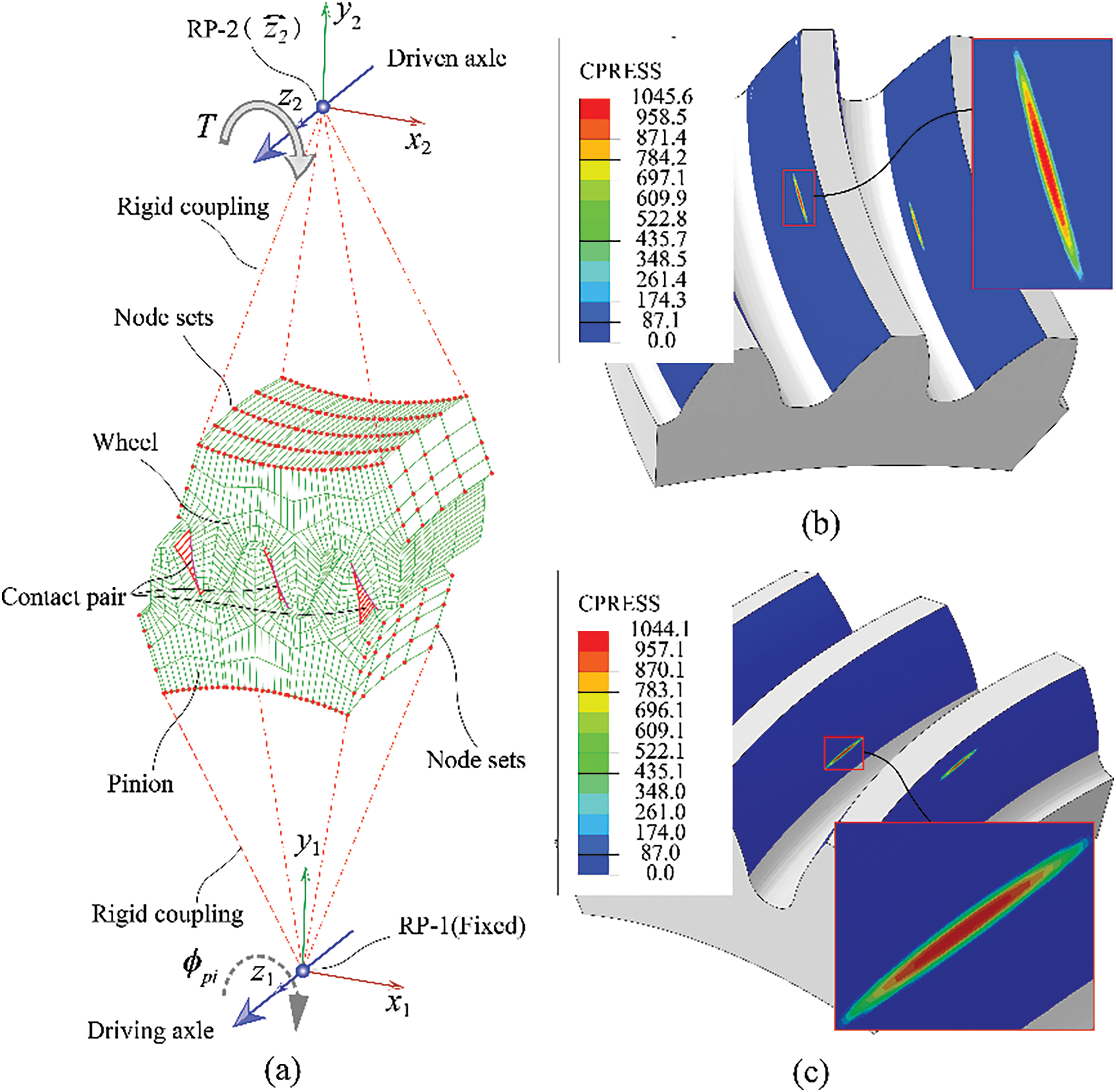
Figure 1: Definition and results of the FEM of the gear pair: (a) Definition of the FEM; (b) Contact pressure on the gear tooth surfaces; (c) Contact pressure on the pinion tooth surfaces
(3) Output Control. The FEM software can directly output the normal force at each node on the contact tooth surface. By summing the normal forces at all nodes on the tooth surface, the total normal load on the tooth surface can be obtained [36]. However, due to the curvilinear shape of the tooth surface in the longitudinal direction, the normal forces at each node on the tooth surface are not aligned, meaning the total load cannot be calculated by simply summing the nodal normal forces. Instead, the normal load can be indirectly determined through the contact pressure distribution on the tooth surface. Therefore, in the FEM software, it is only necessary to output the contact pressure and the coordinates of the contact surface nodes. To further enhance computational efficiency, the output of irrelevant results was disabled. The resulting files are used for subsequent calculations of the normal pressure, curvature, and velocity on the tooth surface. The results for a specific meshing position are shown in Fig. 1b,c, where Fig. 1b displays the contact pressure contour on the wheel tooth surface, and Fig. 1c shows the contact pressure contour on the pinion tooth surface.
2.2 Prepare Data for EHL Analysis
The primary data required for EHL analysis include the normal load at the tooth contact points, the entrainment speed and slip-roll ratio at the contact points, and the effective radius in the vicinity of the contact points. To obtain these gear meshing data, a Python script was developed to extract the normal forces and the coordinates of the meshing points from the FEM results. The script then combines these with analytical methods to calculate the entrainment speed and effective radius. The basic workflow for data processing is illustrated in Fig. 2.
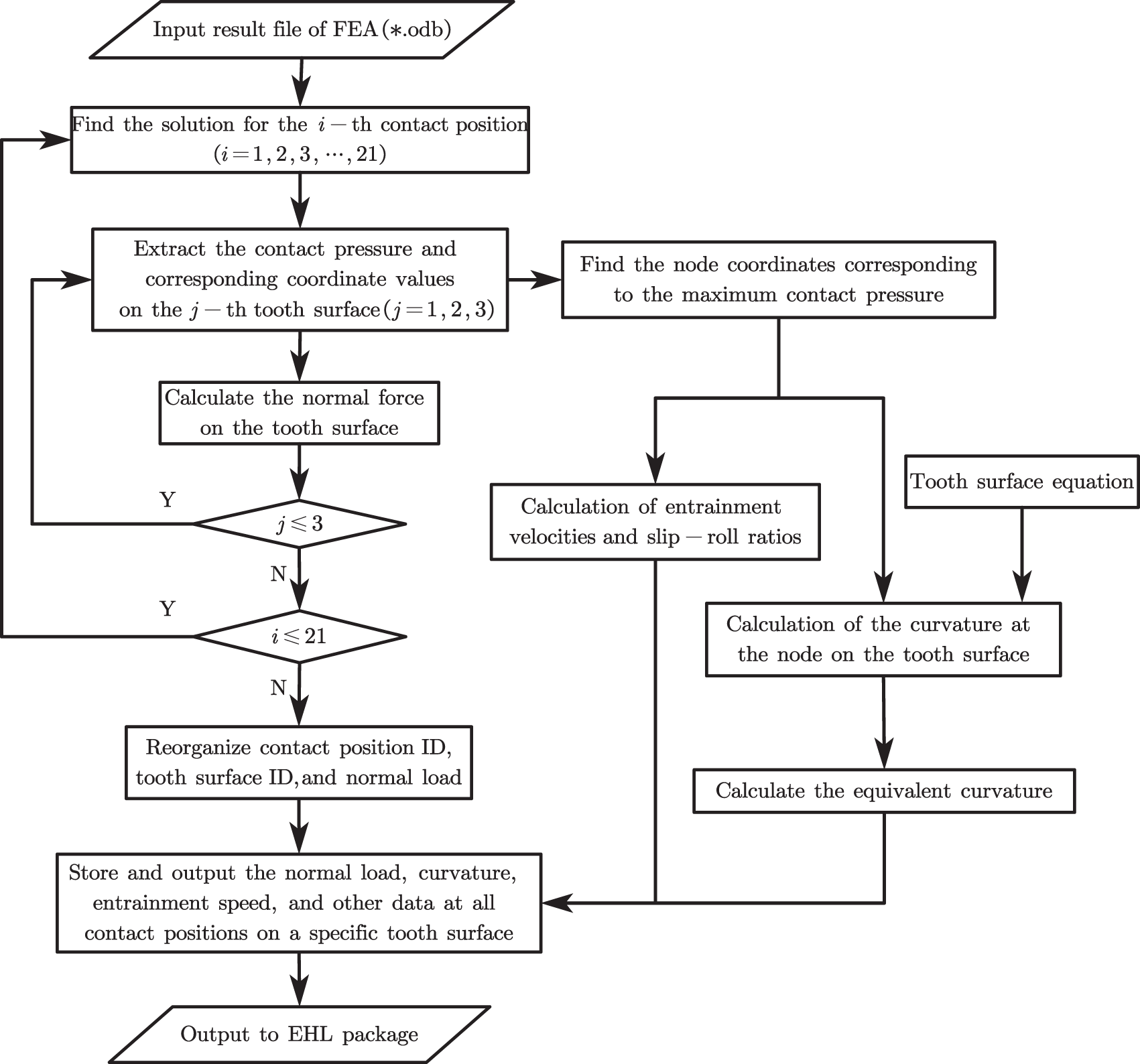
Figure 2: Flowchart for obtaining input parameters for the EHL model
In the workflow, the FEM result file (*.odb) serves as the input for the Python script. The script extracts the coordinates of all nodes on the three tooth surfaces at the i-th contact location, as well as the corresponding contact pressure values for each node. The normal force on each contact tooth surface and the coordinates of the node with the maximum contact pressure on each surface are then determined. This node is treated as the contact point on the tooth surface, and based on this node, the entrainment speed and the surface curvature (effective radius) at the contact point are calculated. The calculation of the contact point curvature requires the tooth surface equation. In this study, the surface of the second tooth (the tooth in the middle) is selected as the object of EHL analysis. The normal force, entrainment speed, and surface curvature at each contact instant on this tooth surface are re-evaluated, organized, and stored in a specified format for subsequent EHL analysis.
2.2.1 Normal Force Calculation
After solving the FEM of the gear, the nodal coordinates on the tooth surface and the corresponding contact pressure distribution can be obtained, as shown in Fig. 3a. The contact pressure is highest at the center of the distribution, which corresponds to the center of the contact ellipse. This point of maximum pressure is identified as the contact point on the tooth surface. During a meshing cycle, a series of such contact points appear on the tooth surface, and the line connecting these points forms the path of contact. All contact points along this path satisfy the load distribution factor curve. As shown in the figure, the load distribution factor is minimal (i.e., the normal load is minimal) when the gear is entering or exiting the mesh. This is because multiple teeth are in contact during the entry and exit phases of meshing, and the load on a single tooth surface is shared by adjacent teeth, as illustrated in Fig. 3b–d. The load on the tooth surface reaches its maximum only during single-tooth contact, where the contact point is located in the central region of the tooth surface. In this section, we aim to calculate the normal load at each contact point on the same tooth surface.
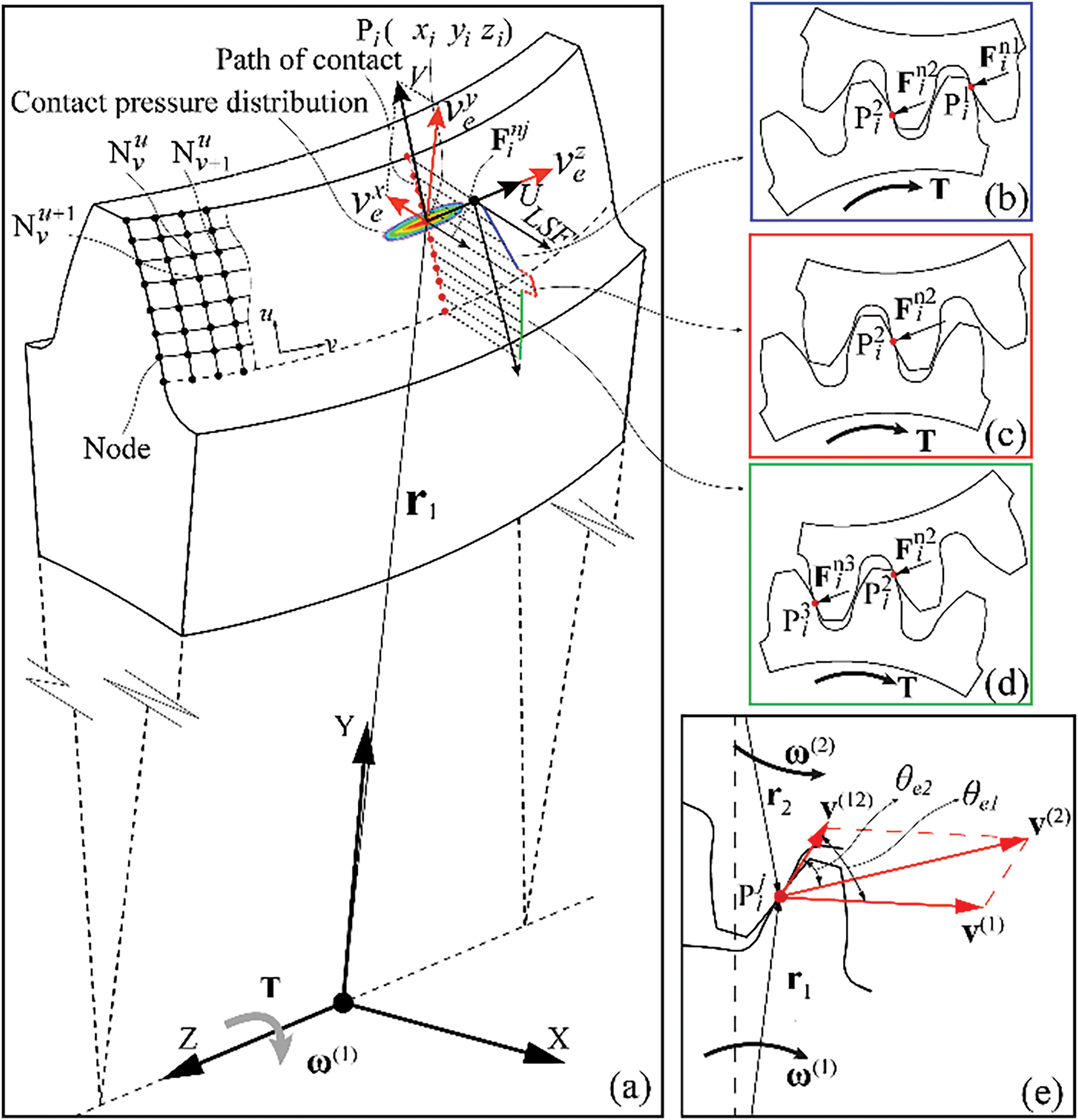
Figure 3: Illustration of forces and velocities induced by gear pair meshing: (a) Contact pressure distribution at the nodes on the tooth surface; (b) Normal force at the contact point when double-tooth are meshing; (c) Normal force at the contact point when entering meshing; (d) Normal force at the contact point when exiting meshing; (e) Meshing velocity at the contact point
Under the action of a normal load Fn, two continuous surfaces come into contact, and a contact ellipse forms in the vicinity of the contact point. The contact pressure at any point within the contact ellipse can be represented as a function P(u,v), where the variable u represents the coordinate value in the profile direction, and v represents the coordinate value in the longitudinal direction. If the pressure distributions in the u and v directions are separated, the contact pressure distribution in the longitudinal direction can be denoted as P(v), and the stress distribution in the profile direction can be denoted as P(u). Both functions represent the unit load on the tooth surface, measured in N/mm. The relationship among these three pressure distribution functions is given as follows:
In the equation, u0 and uf represent the lower and upper bounds of the dimensions in the profile direction, respectively, while v0 and vf represent the lower and upper bounds of the dimensions in the longitudinal direction, respectively.
The normal force that induces continuous surface contact deformation can be determined using Eq. (2).
In the equation, parameter B denotes the width of the gear.
However, in this study, we obtained only a series of discrete nodal coordinates and contact pressures on the contact surface from the FEM, making it impractical to solve using a continuous surface normal force approach. Instead, we can use the trapezoidal rule based on Eq. (1) to solve the pressure distribution in both the profile and longitudinal directions. The pressure distribution in the profile direction can be calculated using Eq. (3).
Here, r represents the position vector of a node on the tooth surface (the final description of the position vector see [26]), and p is the pressure value at that node. The superscript u indicates the row in which the node is located, where u = 1, 2, 3, …, k, and v indicates the column, where v = 1, 2, 3, …, l. k is the total number of rows of tooth surface nodes, and l is the total number of columns of tooth surface nodes.
Assume that the normal force at the i-th meshing position on the j-th tooth surface is denoted as
2.2.2 Solution of Entrainment Speed
During the meshing process of a gear pair, both relative sliding and relative rolling occur between the two tooth surfaces, with the positions of sliding and rolling necessarily occurring at the contact point
Assuming the rotational speed of the pinion is N, its angular velocity is expressed as:
The angular velocity of the wheel about its axis of rotation can be expressed as:
In Eq. (6), the matrix Mdev represents the assembly error matrix of the gear pair.
In Eq. (7), the calculation methods for matrices Mf,k, Mk,l, Ml,m, Mm,n can be found in [41]. Among them, the matrix Mf,k is the center distance error matrix of the gear pair; the matrix Mk,l is the axial displacement error matrix; the matrix Ml,m is the crossing shaft angle error matrix; the matrix Mm,n is the intersecting shaft error matrix.
In Eqs. (5) and (6), the angular velocities of the pinion and the wheel are denoted as follows:
The position vector r1 at the contact point on the pinion tooth surface can be determined based on the coordinates of the point with the maximum contact pressure extracted from the FEM. The position vector r2 at the contact point on the wheel can be expressed as:
In this equation, Ldev represents a 3 × 3 matrix formed by the first three rows and the first three columns of the matrix Mdev.
The velocities at the meshing point
The tangential relative velocity at the meshing point
The entrainment velocity on the tooth surface at the point of tangency can be expressed as:
where the angles θe1 and θe2 between the velocities of the two gears and the tangential relative velocity are given by:
The entrainment velocities (See Fig. 3a) along the major and minor axes of the contact ellipse on the tooth surface are given by:
where U, V are the components of the entrainment velocity along the major and minor axes of the ellipse.
The slip-roll ratios along the major and minor axes of the ellipse are given by:
where ξu and ξv are the components of the entrainment velocity along the major and minor axes of the ellipse, respectively (in m/s).
2.2.3 Calculation of the Equivalent Radius of the Tooth Surface
Assume that the tooth surface equation is represented by the vector r, and the corresponding normal vector is denoted by n. Both r and n are functions of the variables u and θ, where u represents the variable in the tooth profile direction, and θ represents the rotation angle of the face milling cutter along the tooth width direction. For a detailed derivation of the tooth surface equation, please refer to the literature [41]. According to Gaussian surface theory, the two principal curvatures
Here, E = ru·ru, F = ru·rθ, G = rθ·rθ, L = ruu·n, M = ruθ·n, N = rθθ·n. Where ru = ∂r/∂u, rθ = ∂r/∂θ, ruu = ∂(∂r/∂u)/∂u, rθθ = ∂(∂r/∂θ)/∂ θ, ruθ = ∂(∂r/∂u)/∂θ.
Simultaneous,
The principal directions corresponding to the two principal curvatures of the tooth surface can be expressed by Eq. (20).
The angle σ between the corresponding principal curvatures at any contact point on the two tooth surfaces can be expressed by Eq. (21). The geometric meanings of these parameters are shown in Fig. 4.
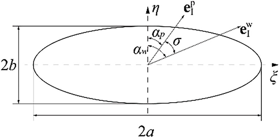
Figure 4: Schematic diagram of the principal curvature and the inclination angle of the contact ellipse
In these equations,
The angle between one of the principal directions at the meshing point on the pinion tooth surface and the minor axis of the contact ellipse is denoted by αp. Similarly, the angle between one of the principal directions at the meshing point on the wheel tooth surface and the minor axis of the contact ellipse is denoted by αw. These two angles can both be used to represent the direction of the entrainment speed at the contact point between the two tooth surfaces. They can be expressed by Eq. (22).
Here,
The equivalent radius at the meshing point between the two tooth surfaces is expressed by Eq. (23).
In this equation, Rx represents the equivalent radius in the longitudinal direction of the tooth, and Ry represents the equivalent radius in the profile direction of the tooth.
Current research on the EHL of gears has become quite extensive, encompassing not only isothermal EHL but also considerations of non-Newtonian fluid effects, temperature effects (non-isothermal conditions), surface roughness, and more. Given that this study represents the first investigation into the EHL performance of curvilinear cylindrical gears, the most fundamental isothermal EHL model is employed as the research tool. Future work can incorporate additional factors to further explore the EHL performance of this type of gear.
Isothermal EHL is a complex lubrication state that examines the thin-film lubrication between elastic surfaces, particularly under high load and low-speed conditions, such as in gears, rolling bearings, and cam mechanisms. Under these conditions, the lubrication film thickness is extremely thin, and the lubricant is subjected to very high pressures, leading to a significant increase in its viscosity. Additionally, due to the substantial contact pressures, the elastic deformation of the contact surfaces cannot be neglected.
The establishment of the isothermal EHL mathematical model primarily involves the following key equations:
(1) Reynolds equation. The Reynolds equation describes the pressure distribution within the lubrication film and is the core of the EHL model. This equation considers the flow behavior of the lubricant as well as the movement of the contact surfaces. The two-dimensional form of the equation is given by:
Here, p represents the pressure distribution; h is the lubricant film thickness; ρ is the lubricant density;
η is the lubricant viscosity; U and V are the entrainment velocities at the center of the contact ellipse along the major and minor axes of the contact ellipse, respectively (Fig. 3a).
(2) Film thickness equation. The lubricant film thickness h depends not only on the geometric shape but also on the elastic deformation caused by pressure. Based on the typical Hertzian contact theory, the film thickness can be expressed as:
where h0 is the film thickness at the reference position; Rx and Ry are the radii of curvature of the contact surfaces; E′ is the effective elastic modulus, and A is the contact area.
(3) Equation of state. The viscosity and density of the lubricant are generally functions of pressure, which can be described by the equation of state. For example, the relationship between lubricant viscosity and pressure is often described by the Roelands model:
where η0 is the environmental viscosity of lubricating oil, and α is the pressure-viscosity coefficient. The relationship between lubricant density and pressure can be approximately expressed as:
where ρ0 is the environmental density of lubricating oil.
(4) Load balance equation. The load balance equation refers to the equilibrium relationship between the pressure distribution of the oil film on the contact surfaces under lubrication conditions and the external load Fn.
(5) Boundary conditions. Typical boundary conditions include zero pressure at the boundaries of the contact area and continuity of film thickness at the inlet and outlet.
In the above equations, x0 represents the inlet boundary of the computational domain in the X-direction, and xe represents the outlet boundary in the Y-direction. Similarly, y0 and ye denote the inlet and outlet boundaries of the computational domain in the Y-direction, respectively. Due to the complexity of these equations, the isothermal EHL problem is typically solved using numerical methods such as the finite difference method, finite element method, or multilevel method. These numerical approaches generally require iterative solutions to achieve a balance between pressure distribution, film thickness distribution, and elastic deformation. Before performing further numerical calculations for the EHL model, to assess the generality and stability of the solution method, it is necessary to transform the governing equations into a dimensionless form. The main dimensionless variables are defined as follows:
The primary focus of this paper is to investigate the influence of five key factors—assembly errors, tooth surface modification amounts, driving torque, face-milling cutter radius, and the estimated contact pattern ratio—on the EHL characteristics of gears. These five parameters have been extensively studied in our previous work, and the methods to obtain them will not be reiterated here, please refer to references [7,41] for detailed information. The estimated contact pattern ratio, denoted as Lc, refers to the percentage of the major axis dimension of the estimated contact ellipse relative to the tooth width.
The fixed-setting face-milled curvilinear cylindrical gear is machined using three types of face-milling cutters. A double-edged face-milling cutter is used for machining the pinion, with its equivalent radius denoted as R. Additionally, two single-edged face-milling cutters are used to machine the concave and convex tooth surfaces of the wheel, with their equivalent radii denoted as rob and rib, respectively. The geometric meanings of the parameters R, rib, and rob can be found in [44]. The tooth surface modification amount refers to parabolic crowning in the tooth profile direction, which is implemented to eliminate tip contact during gear meshing. The modification coefficient is represented by apf (The geometric meanings can be found in [26]) Assembly error refers to deviations that may occur during the actual assembly of the gear pair. In this study, we focus on the impact of the crossing shaft angle error, denoted by ΔH (The geometric meanings can be found in reference [44]), which has the most significant effect on meshing performance, and its influence on EHL performance.
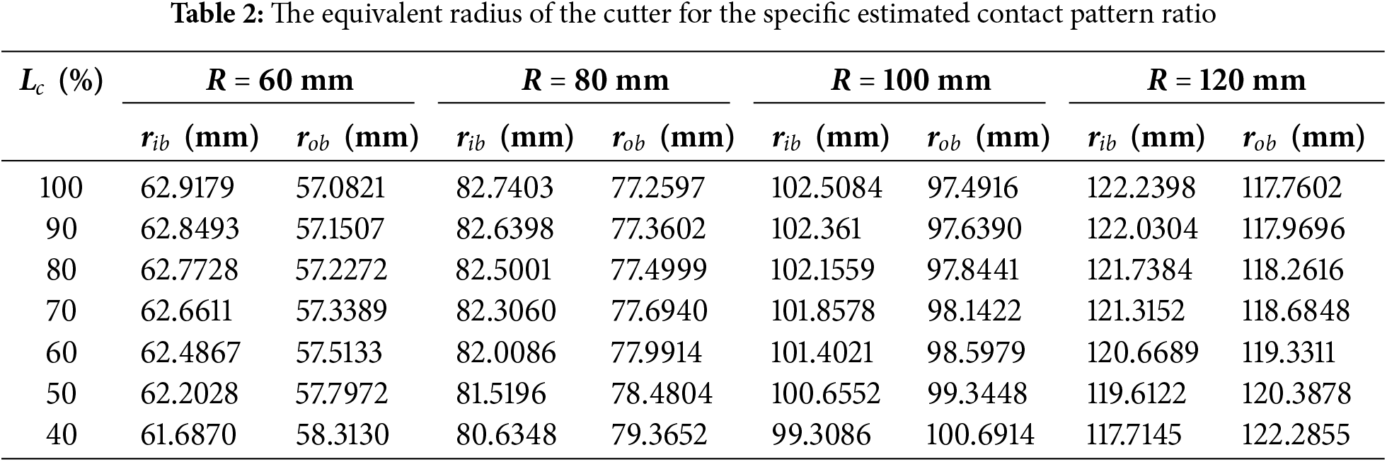
The basic parameters of the gear pair and the lubricant used in all the example studies are provided in Table 1. The relationship between various face-milling cutter radii and the estimated contact pattern ratio is shown in Table 2. In subsequent example studies, one or more sets of these cutter data may be used.
To ensure the accuracy of the solution, all example studies were solved using the equidistant multigrid method, with a total of five grid levels. The numerical calculation domain was set to −4.5 ≤ X ≤ 1.5, −1.8ke ≤ Y ≤ 1.8ke, 0 ≤ Z ≤ 3.05, where ke represents the ratio of the major to minor axes of the Hertzian contact ellipse.
3.1 Influence of Assembly Errors
The study focuses on the crossing shaft angle error (ΔH) of the gear pair, with values set at 0°, 0.005°, and 0.1°. To ensure that there is no interference on the tooth surface under these shaft angle errors, the center distance error (ΔC) is set to 0.1 mm. Additionally, the tooth surface modification coefficient apf is set to 0.0004, the resistance torque (T) is 150 N·m, the radius of the double-edged cutter (R) is 60 mm, and the single-edged cutter radii for the pinion are rib = 62.2028 mm and rob = 57.7972 mm. The contact pattern ratio is 50%.
During a single meshing cycle, from the beginning to the end of the engagement, the distribution of lubricant film pressure and film thickness on the tooth surface is shown in Fig. 5. The figure indicates that as the pinion rotation angle increases, the lubricant film pressure initially rises and then decreases, while the film thickness first decreases and then increases. At a pinion rotation angle (φp) of 10.45°, the lubricant film pressure reaches its maximum, and the film thickness reaches its minimum. According to the tooth surface load distribution shown in Fig. 3a, it can be observed that around φp = 10.45°, the gear pair is in a single-tooth engagement state, resulting in the maximum normal force on the tooth surface, which in turn increases the film pressure in the middle region of the tooth surface and reduces the film thickness. As the pinion rotation angle remains the same, the width of the lubricant film distribution along the longitudinal direction of the gear slightly decreases with increasing assembly error. However, it is difficult to discern the impact of assembly errors on film pressure and thickness from the lubricant film distribution cloud plots. To evaluate the EHL performance of the gear, the maximum lubricant film pressure and minimum film thickness are extracted from the cloud plots and subjected to comparative analysis.
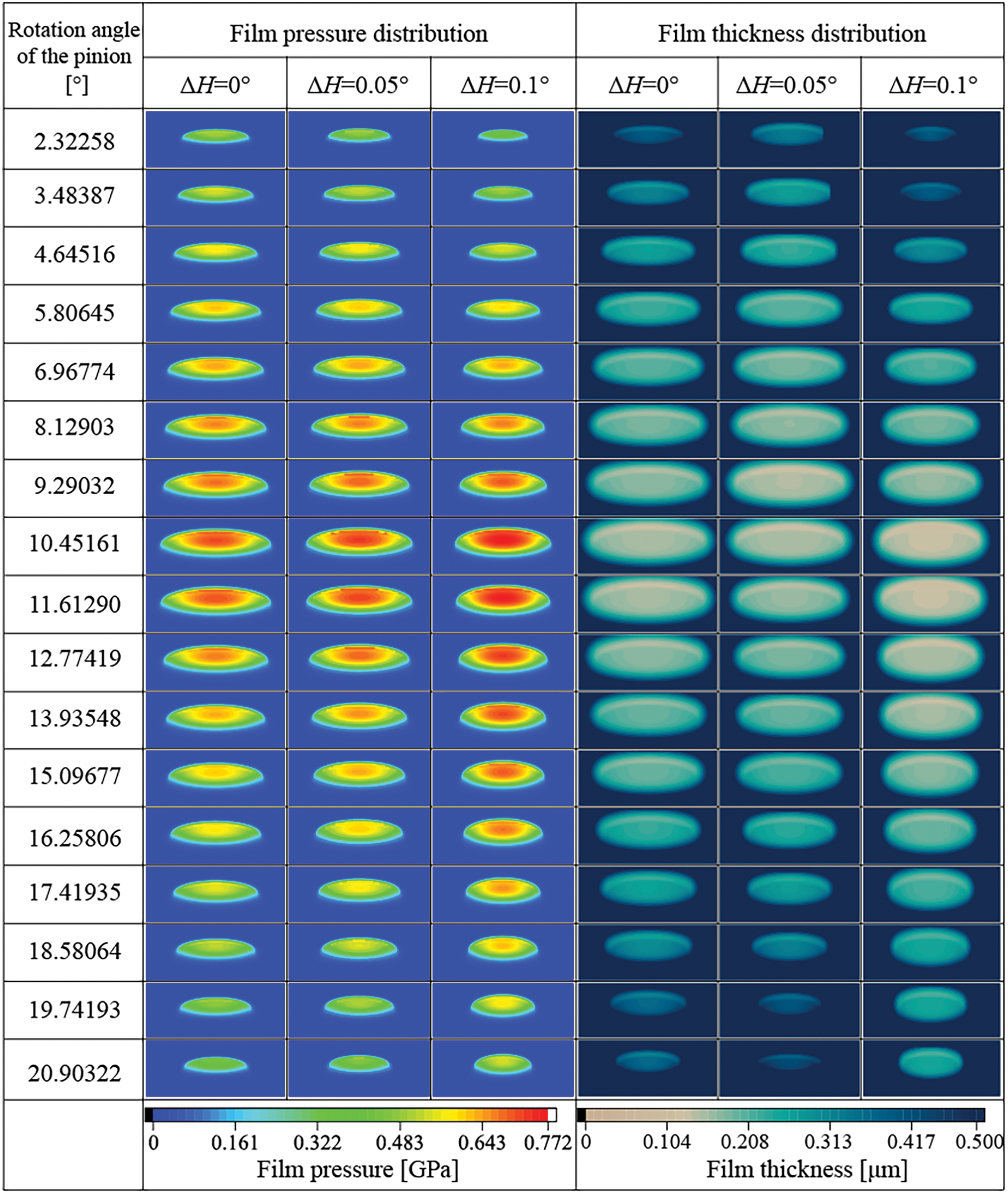
Figure 5: Film pressure and thickness distribution on the tooth surface during one meshing cycle
Fig. 6 shows the maximum oil film pressure and minimum oil film thickness extracted from Fig. 5. As illustrated in Fig. 6a, when φp ≤ 5.81°, the minimum oil film thickness increases with the increase in assembly error. When φp ≥ 9.29°and ΔH = 0.1°, the minimum oil film thickness is at its lowest. Specifically, when φp = 10.45°, the minimum film thickness is the smallest throughout the entire meshing cycle. In Fig. 6b, it can be observed that when φp ≤ 8.13°, the maximum oil film pressure within the meshing interval decreases with increasing assembly error. However, when φp ≥ 8.13°, the trend reverses, with the maximum oil film pressure increasing as the assembly error grows. Additionally, when φp ≥ 10.45°, the impact of assembly error on maximum oil film pressure becomes more pronounced. The maximum oil film contact pressure occurs at φp = 10.45°during the entire meshing cycle. In summary, excessive crossing shaft angle error is detrimental to the lubrication of the gear pair. When ΔH ≥ 0.1°, the variations in oil film thickness and pressure are most significant.
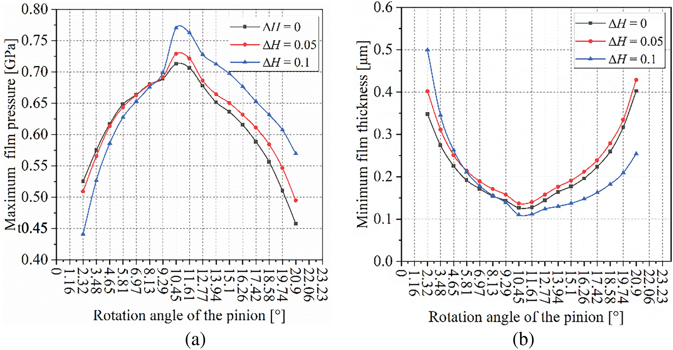
Figure 6: The effect of assembly errors on the lubricant film: (a) Minimum oil film thickness; (b) Maximum oil film pressure
3.2 Influence of Tooth Surface Modification Amount
Tooth surface modification can result in smoother transmission, reduced noise and vibration, and elimination of stress concentrations and wear caused by edge contact at the tooth tip. In this subsection, the tooth surface modification coefficient apf is considered under six conditions: 0, 0.0001, 0.0002, 0.0003, 0.0004, and 0.0005. Additionally, the gear pair is assumed to be in an ideal assembly state, with a resistance torque T = 150 N·m, a double-edged face-milling cutter radius R = 60 mm, a single-edged face-milling cutter radius rib = 62.9179 mm, and rob = 57.0821 mm, with a contact pattern ratio on the tooth surface of 100%.
Fig. 7 illustrates the impact of tooth surface modification on the lubricant film. In Fig. 7a, the lubricant film profiles under various tooth surface modifications appear disorganized. However, at φp = 10.45°, the amount of modification does not affect the film thickness, which remains at its minimum value during the meshing cycle. When apf ≤ 0.001 and φp ≤ 2.32°, a slight increase in minimum film thickness is observed, attributed to the higher peak normal load caused by edge contact at the tooth tip, as shown in Fig. 8a. In Fig. 8a, the peak load at the meshing position gradually decreases with a reduction in modification amount when φp = 1.16°, indicating the elimination of edge contact at the tooth tip, thereby restoring normal lubrication conditions.
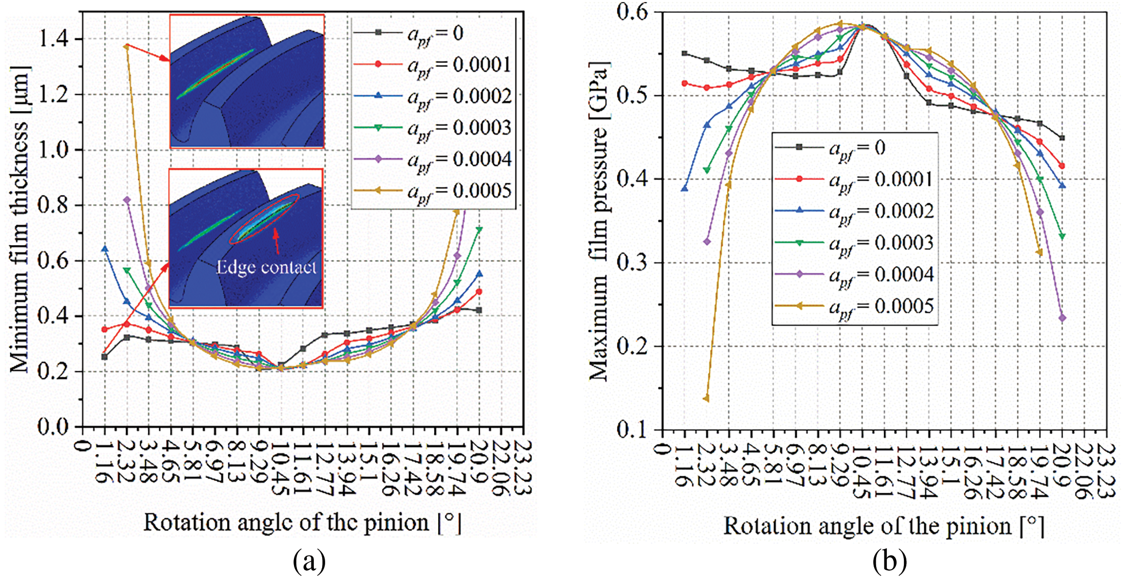
Figure 7: The influence of modification amount on the lubricating oil film: (a) Minimum oil film thickness; (b) Maximum oil film pressure
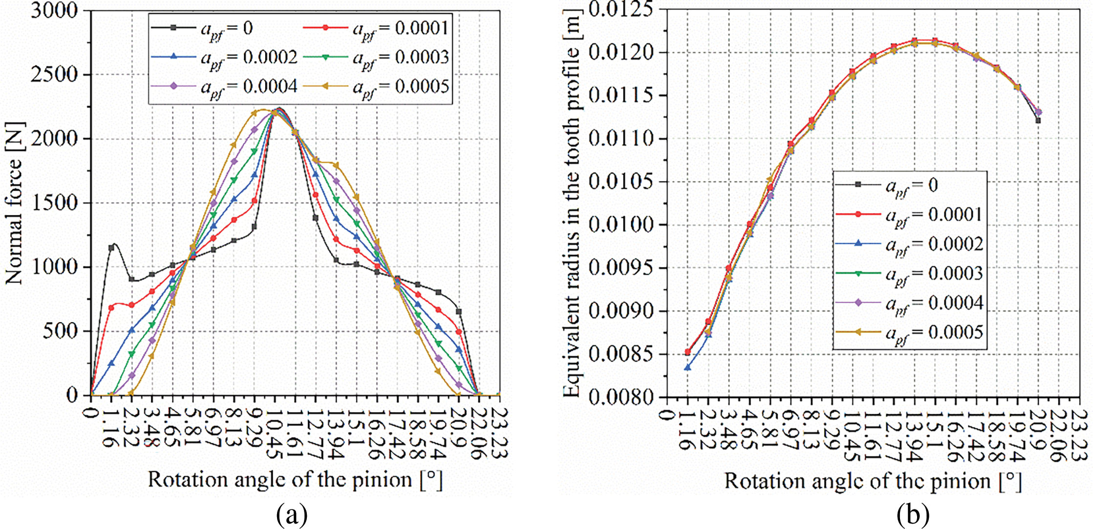
Figure 8: Influence of modification amount on normal load and equivalent radius: (a) Normal load on the tooth surface; (b) Equivalent radius in the tooth profile
In Fig. 8a, the meshing cycle can be divided into four segments: Segment 1 (φp = 0~5.81°), Segment 2 (φp = 5.81~10.45°), Segment 3 (φp = 10.45~17.42°), and Segment 4 (φp = 17.42~23.23°). In Segments 1 and 4, the normal load decreases with an increase in modification amount, leading to an increase in minimum film thickness as the modification amount increases. In Segments 2 and 3, the normal load increases with an increase in modification amount, resulting in a decrease in minimum film thickness as the modification amount increases.
In this example study, since the face-milling cutter radius used to machine the gear pair remains constant, the effective radius in the longitudinal direction of the tooth surface also remains unchanged (Fig. 8b). However, the modification amount does have some impact on the effective radius in the profile direction. Therefore, only the normal load on the tooth surface affects the lubricant film. The variation of maximum film pressure and minimum film thickness during the meshing cycle in Fig. 7b closely resembles the pattern of normal load on the tooth surface. However, when φp ≤ 9.29°, the maximum film pressure of the unmodified gear pair gradually decreases, which is also due to the edge contact at the tooth tip of the unmodified gear.
In summary, tooth surface modification can eliminate edge contact at the tooth tip, reducing contact forces at the top and bottom of the tooth surface. This results in an increase in lubricant film thickness and a reduction in pressure, thereby improving the lubrication performance of the gear.
3.3 Influence of Resistance Torque
In this section, the torque applied to the gear is set at 50, 100, 150, and 200 N·m, respectively, while the gear pair is assumed to be in an ideal assembly state. The radius of the double-edged face-milling cutter is set to R = 60 mm, the tooth surface modification coefficient apf = 0.0004, and the radii of the single-edged face-milling cutters are rib = 62.4867 mm and rob = 57.5133 mm, respectively. The contact pattern ratio of the tooth surface is set to 60%.
The minimum lubricant film thickness during the meshing cycle is shown in Fig. 9a. It can be observed that as the torque increases, the minimum oil film thickness gradually decreases. When the torque increases to a certain level, the impact of the torque on the lubricant film becomes less significant as the gear teeth engage near the middle of the tooth surface. The variation in torque has a more substantial effect on the oil film thickness at the beginning and end of the meshing process. Similarly, the maximum oil film pressure distribution during the meshing cycle increases with the increase in torque, as shown in Fig. 9b. Overall, under the same conditions, a moderate increase in load can improve the lubrication performance of the gear pair, while an excessive load results in a diminished sensitivity of lubrication performance improvement.
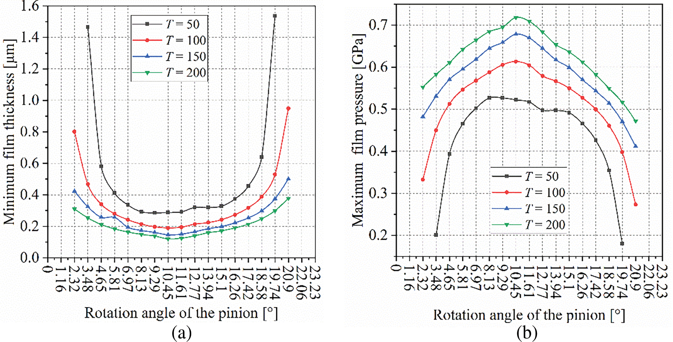
Figure 9: Influence of resistance torque on lubricating oil film: (a) Minimum oil film thickness; (b) Maximum oil film pressure
3.4 Influence of the Equivalent Radius of the Face-Milling Cutter
This subsection focuses on three primary aspects: (1) The impact of tooth curvature on the lubrication film under a constant contact pattern ratio. (2) The effect of varying contact pattern ratios on the lubrication film under consistent tooth curvature conditions. (3) The influence of the coupling between contact pattern ratio and tooth curvature on the lubrication film. A total of 28 example studies were conducted, with tooth surface modification parameters set to 0.0004, and a torque of 150 N·m was applied. The gear pair is assumed to be in an ideal assembly state. The face milling cutter parameters for the two gears are provided in Table 2.
Fig. 10 illustrates the impact of tooth curvature on the lubrication film when the contact pattern ratio is 100%. As observed from the figure, regardless of the degree of tooth curvature, the oil film thickness and pressure remain nearly unchanged. This indicates that when the contact pattern ratio is consistent, the lubrication performance of the gear remains unchanged.
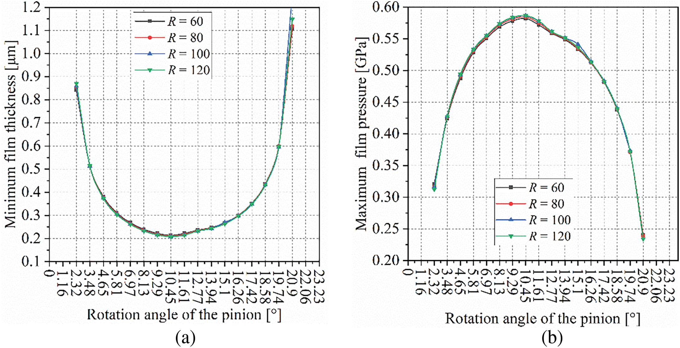
Figure 10: Influence of tooth flank curvature radius on lubricating oil film: (a) Minimum oil film thickness; (b) Maximum oil film pressure
When the tooth curvature radius R = 60 mm, the effect of the estimated contact pattern ratio on the oil film thickness is shown in Fig. 11a. The minimum oil film thickness within the meshing cycle increases with an increasing contact pattern ratio, while the maximum oil film pressure decreases as the contact pattern ratio increases. This trend is caused by the inconsistency in the effective radius in the longitudinal direction of the tooth surface at the meshing point (Fig. 12). It suggests that a larger contact pattern on the tooth surface is more favorable for the lubrication of the gear pair.
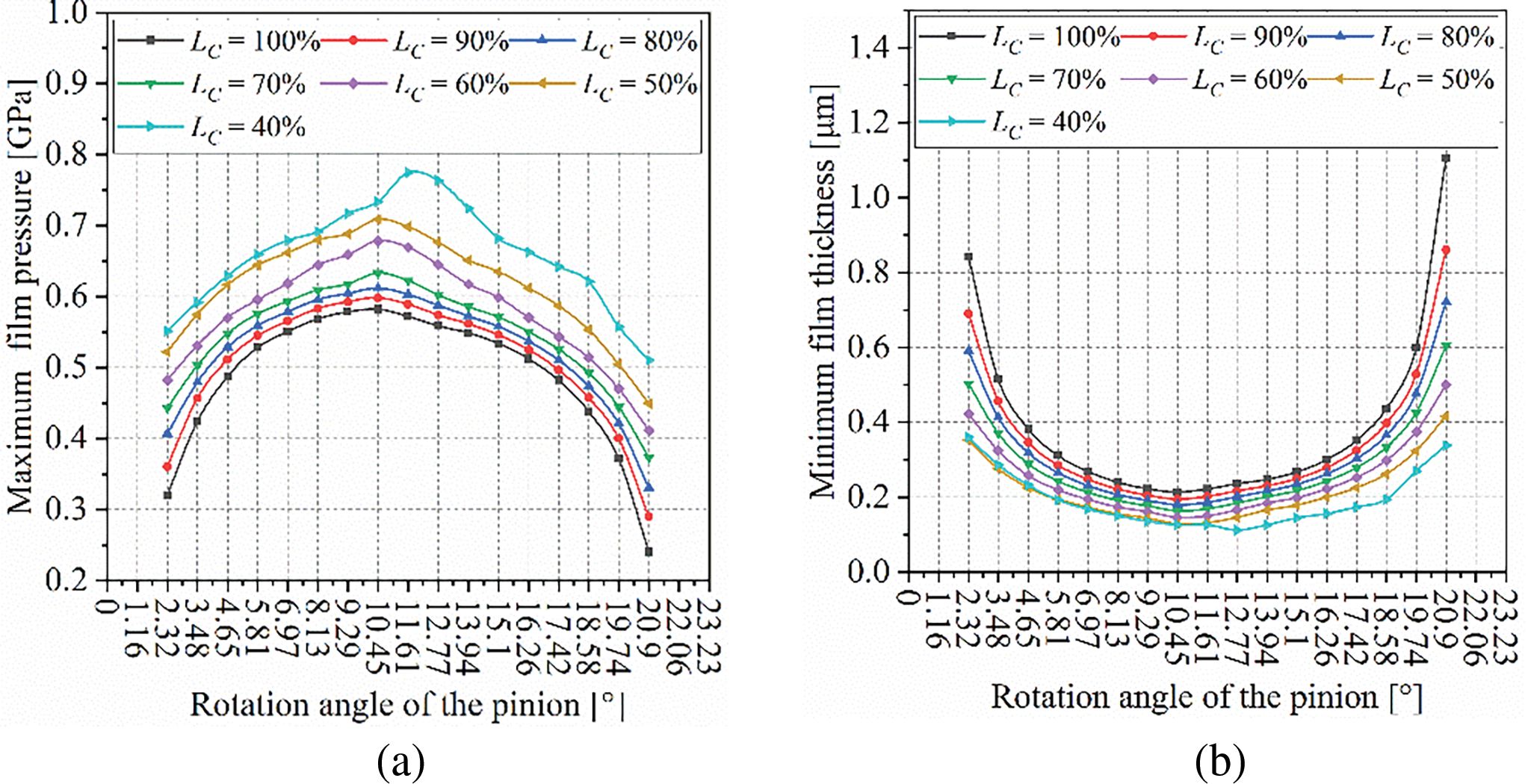
Figure 11: The effect of contact pattern ratio on the lubricant film thickness: (a) Minimum oil film thickness; (b) Maximum oil film pressure
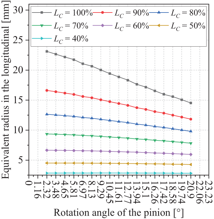
Figure 12: The equivalent radius of the tooth surface in the longitudinal direction
Fig. 13 illustrates the relationship between the lubricant film thickness on the tooth surface throughout a complete meshing cycle and the contact pattern ratio, as well as the equivalent radius of the double-edged face-milling cutter (i.e., the curvature radius in the longitudinal direction of the gear teeth). The impact of the equivalent radius of the double-edged face-milling cutter on lubrication is minimal, whereas the contact pattern ratio has the most significant influence on lubrication performance. As the contact pattern ratio decreases, the minimum film thickness decreases, and the maximum film pressure increases. In other words, the lubricant film is independent of the tooth curvature radius, and a larger contact pattern ratio on the tooth surface is more beneficial for the lubrication of the gear pair, thereby resulting in relatively better mechanical performance.
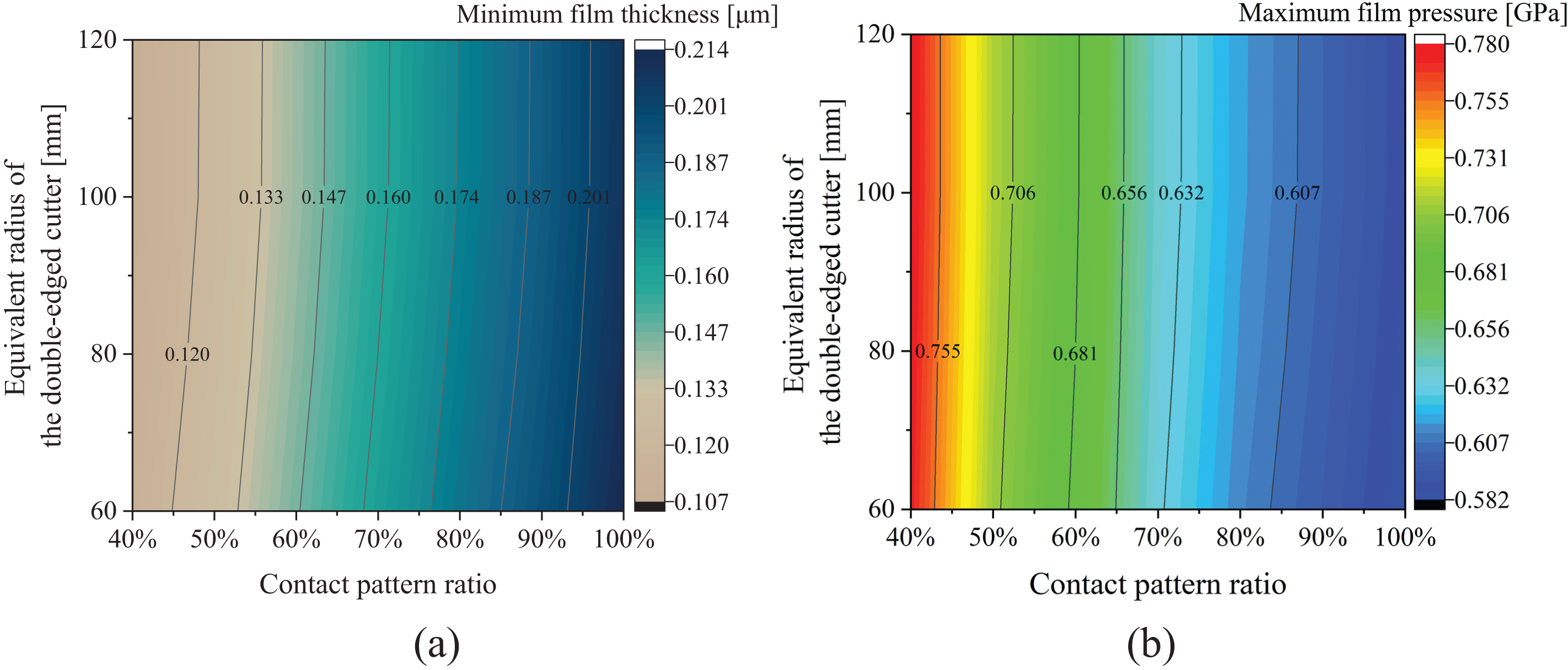
Figure 13: The effect of contact pattern ratio and equivalent radius of the face milling cutter on the oil film: (a) Minimum oil film thickness; (b) Maximum oil film pressure
The study draws the following conclusions:
(1) Utilizing the FEM to provide input data for EHL simulations reveals the phenomenon of tooth tip edge contact caused by tooth deformation, which is not detected when using traditional LTCA programs. As a result, the impact of tooth-tip edge contact may be overlooked during EHL simulations. Tooth surface modification can eliminate the abrupt load changes caused by edge contact at the tooth tip, thereby improving the lubrication conditions during gear meshing entry and exit. However, during single-tooth meshing, the improvement in lubrication performance due to tooth surface modification is not significant.
(2) Due to the relatively low normal load when the gear pair enters and exits meshing, the oil film thickness is greater, and the oil film pressure is lower during these periods. The lubrication condition is the worst when the gear pair is in a single-tooth meshing state. Excessive assembly errors are detrimental to the lubrication performance of the gear pair, while skew assembly errors below 0.05° have a minimal impact on lubrication performance. An increase in resistance torque leads to an increase in normal load, which in turn reduces the oil film thickness and increases the oil film pressure. Under the same conditions, reducing the load is beneficial for improving the lubrication performance of the gear pair.
(3) If both gears of a curvilinear gear pair are machined with a double-edged face-milling cutter, the lubrication performance improves as the cutter radius increases. If the cutter radius for machining the wheel remains unchanged, the lubrication performance increases as the radius of the single-edged face-milling used for machining the pinion increases. This result is due to the fact that the cutter radius used to machine the gear pair affects the size of the contact pattern of the gear pair.
(4) The main limitation of this research work is that the curvature and normal pressure at the meshing points on the tooth surface are calculated based on the finite element model of the gear pair. Therefore, the higher the number of nodes on the tooth surface, the higher the accuracy of the solution. It is strongly recommended to have as many nodes as possible in the direction of the tooth surface meshing line.
Acknowledgement: This research was supported by the Sichuan Science and Technology Program, Panzhihua City Provincial Targeted Financial Resources Transfer Payment, the Key Laboratory of Process Equipment and Control in Sichuan Province, Panzhihua University, Sichuan Provincial Engineering Technology Research Center for Advanced Manufacturing of Titanium Alloys, Panzhihua Key Laboratory of Advanced Manufacturing Technology. We extend our sincere thanks to these institutions for their generous support, which made this research possible.
Funding Statement: This research was funded by the Sichuan Science and Technology Program (Project Nos. 2024NSFSC0140, 2023NSFSC0414, 2022NSFSC0454), Panzhihua City Provincial Targeted Financial Resources Transfer Payment (Grant No. 222Y2F-GG-04), Open Project of the Key Laboratory of Process Equipment and Control in Sichuan Province (Project No. GK202211), Cultivation Research Project of Panzhihua University (Project No. 2023PY11), Open Project of Sichuan Provincial Engineering Technology Research Center for Advanced Manufacturing of Titanium Alloys (Project No. TM-2023-Z-02), Open Project of Panzhihua Key Laboratory of Advanced Manufacturing Technology (Project No. 2022XJZD05).
Author Contributions: The authors confirm contribution to the paper as follows: study conception and design: Xuegang Zhang; data collection: Xuegang Zhang, Ruiqi Wang; analysis and interpretation of results: Xuegang Zhang, Yingjie Dong, Xian Wei; draft manuscript preparation: Xuegang Zhang, Qi Zhang. All authors reviewed the results and approved the final version of the manuscript.
Availability of Data and Materials: Not applicable.
Ethics Approval: Not applicable.
Conflicts of Interest: The authors declare no conflicts of interest to report regarding the present study.
References
1. Liu S-T. Curvilinear cylindrical gears. Gear Technology. 1988;5:8–12. [Google Scholar]
2. Tseng J-T, Tsay C-B. Mathematical model and surface deviation of cylindrical gears with curvilinear shaped teeth cut by a hob cutter. J Mech Des. 2005;127(5):982–7. doi:10.1115/1.1876437. [Google Scholar] [CrossRef]
3. Peng Y, Song A, Shen Y, Lin X. A novel arc-tooth-trace cycloid cylindrical gear. Mech Mach Theory. 2017;118(2):180–93. doi:10.1016/j.mechmachtheory.2017.08.009. [Google Scholar] [CrossRef]
4. Zheng F, Hua L, Han X, Chen D. Generation of noncircular bevel gears with free-form tooth profile and curvilinear tooth lengthwise. J Mech Des. 2016;138(6):064501. doi:10.1115/1.4033396. [Google Scholar] [CrossRef]
5. Tseng J-T, Tsay C-B. Undercutting and contact characteristics of cylindrical gears with curvilinear shaped teeth generated by hobbing. J Mech Des. 2006;128(3):634–43. doi:10.1115/1.2181605. [Google Scholar] [CrossRef]
6. Tseng R-T, Tsay C-B. Contact characteristics of cylindrical gears with curvilinear shaped teeth. Mech Mach Theory. 2004;39(9):905–19. doi:10.1016/j.mechmachtheory.2004.04.006. [Google Scholar] [CrossRef]
7. Fuentes A, Ruiz-Orzaez R, Gonzalez-Perez I. Computerized design, simulation of meshing, and finite element analysis of two types of geometry of curvilinear cylindrical gears. Comput Methods Appl Mech Eng. 2014;272(1):321–39. doi:10.1016/j.cma.2013.12.017. [Google Scholar] [CrossRef]
8. Fuentes-Aznar A, Ruiz-Orzaez R, Gonzalez-Perez I. Comparison of spur, helical and curvilinear gear drives by means of stress and tooth contact analyses. Meccanica. 2017;52(7):1721–38. doi:10.1007/s11012-016-0515-y. [Google Scholar] [CrossRef]
9. Zhang X, Liang Z. Geometric modeling and CFD simulation of curvilinear cylindrical gear pumps. Iranian J Sci Technol Transact Mech Eng. 2023;47(1):1–17. doi:10.1007/s40997-022-00502-3. [Google Scholar] [CrossRef]
10. Luo P, Wu Y, Liang S, Hou L, Fan Q, Wei Y. TEHL analysis of VH-CATT cylindrical gear transmission in elliptical contact considering time-varying parameters. Adv Mech Eng. 2022;14(2):1–17. doi:10.1177/16878132221081615. [Google Scholar] [CrossRef]
11. Anuradha P, Kumar P. Effect of lubricant selection on EHL performance of involute spur gears. Tribol Int. 2012;50(4):82–90. doi:10.1016/j.triboint.2012.02.006. [Google Scholar] [CrossRef]
12. Zhou C, Xiao Z, Chen S, Han X. Normal and tangential oil film stiffness of modified spur gear with non-newtonian elastohydrodynamic lubrication. Tribol Int. 2017;109(3–5):319–27. doi:10.1016/j.triboint.2016.12.045. [Google Scholar] [CrossRef]
13. Shi X, Sun W, Lu X, Ma X, Zhu D, Zhao B, et al. Three-dimensional mixed lubrication analysis of spur gears with machined roughness. Tribol Int. 2019;140(1–2):105864. doi:10.1016/j.triboint.2019.105864. [Google Scholar] [CrossRef]
14. Ramirez R, Rodríguez A, Fabregas J, Maury H. Modeling and simulation of elastohydrodynamic lubrication in spur gears. CFD Lett. 2024;16(6):120–30. doi:10.37934/cfdl.16.6.120130. [Google Scholar] [CrossRef]
15. Peng Y, Zhao N, Qiu P, Zhang M, Li W, Zhou R. An efficient model of load distribution for helical gears with modification and misalignment. Mech Mach Theory. 2018;121(2):151–68. doi:10.1016/j.mechmachtheory.2017.10.019. [Google Scholar] [CrossRef]
16. Peng Y, Zhao N, Zhang M, Li W, Zhou R. Non-newtonian thermal elastohydrodynamic simulation of helical gears considering modification and misalignment. Tribol Int. 2018;124:46–60. doi:10.1016/j.triboint.2018.03.025. [Google Scholar] [CrossRef]
17. Yang Y, Li W, Wang J, Zhou Q. On the mixed EHL characteristics, friction and flash temperature in helical gears with consideration of 3D surface roughness. Ind Lubr Tribol. 2019;71(1):10–21. doi:10.1108/ILT-04-2017-0113. [Google Scholar] [CrossRef]
18. Changhua H, Shizhu W, Ping H. Multilevel solution of the elastohydrodynamic lubrication of concentrated contacts in spiroid gears. J Tribol. 1993;115(3):481–6. doi:10.1115/1.2921663. [Google Scholar] [CrossRef]
19. Pu W, Wang J, Yang R, Zhu D. Mixed elastohydrodynamic lubrication with three-dimensional machined roughness in spiral bevel and hypoid gears. J Tribol. 2015;137(4):041503. doi:10.1115/1.4030185. [Google Scholar] [CrossRef]
20. Simon VV. Improved mixed elastohydrodynamic lubrication of hypoid gears by the optimization of manufacture parameters. Wear. 2019;438–439:S0043164819300857. doi:10.1016/j.wear.2019.01.053. [Google Scholar] [CrossRef]
21. Qu W, Ding H, Tang J. An innovative semi-analytical determination approach to numerical loaded tooth contact analysis (NLTCA) for spiral bevel and hypoid gears. Adv Eng Software. 2020;149(2):102892. doi:10.1016/j.advengsoft.2020.102892. [Google Scholar] [CrossRef]
22. Ding H, Zhang W, Wu H, Chen T, Li S, Li H, et al. Multi-field coupling lubrication interface heat transfer model for hypoid gear transmission. Int Commun Heat Mass Transfer. 2024;154(12):107451. doi:10.1016/j.icheatmasstransfer.2024.107451. [Google Scholar] [CrossRef]
23. Wang D, Ren S, Zhang Y, Pu W. A mixed TEHL model for the prediction of thermal effect on lubrication performance in spiral bevel gears. Tribol Trans. 2020;63(2):314–24. doi:10.1080/10402004.2019.1688442. [Google Scholar] [CrossRef]
24. Ding H, Deng X, Xiao Y, Wang J, Li R, Zhang G, et al. Rough tooth flank thermal elastohydrodynamic lubrication analysis model of spiral bevel gears. Int J Heat Mass Transfer. 2024;230(12):125778. doi:10.1016/j.ijheatmasstransfer.2024.125778. [Google Scholar] [CrossRef]
25. Wang Y, Wu C, Tang W, Zhao X-F, Lv Q-J, Lian Y. Analysis on isothermal elastohydrodynamic lubrication of orthogonal face gear. Tribol Trans. 2012;55(6):863–71. doi:10.1080/10402004.2012.721920. [Google Scholar] [CrossRef]
26. Zhang X, Liang Z. Mathematical model and contact characteristics of curvilinear cylindrical gears with line contact. J Braz Soc Mech Sci Eng. 2021;43(4):183. doi:10.1007/s40430-021-02894-w. [Google Scholar] [CrossRef]
27. Nijenbanning G, Venner CH, Moes H. Film thickness in elastohydrodynamically lubricated elliptic contacts. Wear. 1994;176(2):217–29. doi:10.1016/0043-1648(94)90150-3. [Google Scholar] [CrossRef]
28. Pu W, Wang J, Zhou G, Xiao K, Li J. Effect of surface topography associated with arbitrary velocity direction on the lubrication film thickness in elliptical contacts. Ind Lubr Tribol. 2018;70(2):444–52. doi:10.1108/ILT-09-2016-0206. [Google Scholar] [CrossRef]
29. Greenwood JA. Elastohydrodynamic lubrication. Lubricants. 2020;8(5):51. doi:10.3390/lubricants8050051. [Google Scholar] [CrossRef]
30. Li S, Kahraman A. A transient mixed elastohydrodynamic lubrication model for spur gear pairs. J Tribol. 2009;132(1):011501. doi:10.1115/1.4000270. [Google Scholar] [CrossRef]
31. Li S, Kahraman A. Influence of dynamic behaviour on elastohydrodynamic lubrication of spur gears. Proc Inst Mech Eng Part J: J Eng Tribol. 2011;225(8):740–53. doi:10.1177/1350650111409517. [Google Scholar] [CrossRef]
32. Bahrami Ghahnavieh A, Akbarzadeh S, Mosaddegh P. A numerical study on the performance of straight bevel gears operating under mixed lubrication regime. Mech Mach Theory. 2014;75:27–40. doi:10.1016/j.mechmachtheory.2014.01.005. [Google Scholar] [CrossRef]
33. Lohner T, Ziegltrum A, Stemplinger J-P, Stahl K. Engineering software solution for thermal elastohydrodynamic lubrication using multiphysics software. Adv Tribol. 2016;2016(2):1–13. doi:10.1155/2016/6507203. [Google Scholar] [CrossRef]
34. Cao W, Pu W, Wang J, Xiao K. Effect of contact path on the mixed lubrication performance, friction and contact fatigue in spiral bevel gears. Tribol Int. 2018;123(4):359–71. doi:10.1016/j.triboint.2018.03.015. [Google Scholar] [CrossRef]
35. Wang Z, Pu W, He T, Wang J, Cao W. Numerical simulation of transient mixed elastohydrodynamic lubrication for spiral bevel gears. Tribol Int. 2019;139(1645):67–77. doi:10.1016/j.triboint.2019.06.032. [Google Scholar] [CrossRef]
36. Dai L, Pu W, Wang J. Mixed EHL analysis of planetary drives with small teeth number difference considering real tooth geometry. Lubr Sci. 2018;30(6):317–30. doi:10.1002/ls.1423. [Google Scholar] [CrossRef]
37. Gan L, Xiao K, Wang J, Pu W, Cao W. A numerical method to investigate the temperature behavior of spiral bevel gears under mixed lubrication condition. Appl Therm Eng. 2019;147:866–75. doi:10.1016/j.applthermaleng.2018.10.125. [Google Scholar] [CrossRef]
38. Jian G, Wang Y, Zhang P, Li Y, Luo H. Thermal elastohydrodynamic lubrication of modified gear system considering vibration. J Cent South Univ. 2020;27(11):3350–63. doi:10.1007/s11771-020-4551-3. [Google Scholar] [CrossRef]
39. Xiao Z, Shi X, Wang X, Ma X, Han Y. Lubrication analysis and wear mechanism of heavily loaded herringbone gears with profile modifications in full film and mixed lubrication point contacts. Wear. 2021;477(24):203790. doi:10.1016/j.wear.2021.203790. [Google Scholar] [CrossRef]
40. Zhou W, Zhu R, Liu W, Shang Y. An improved dynamic transmission error model applied on coupling analysis of gear dynamics and elastohydrodynamic lubrication. J Tribol. 2022;144(5):51601. doi:10.1115/1.4051813. [Google Scholar] [CrossRef]
41. Zhang XG, Huang XB, Gan B. Contact stresses and bending stresses analysis of curvilinear cylindrical gears generated by a face-milling cutter with parabolic profile. Métodos Numér Para Cálc Diseño Ing: Rev Int. 2023;39(4):1–23. doi:10.23967/j.rimni.2023.09.001. [Google Scholar] [CrossRef]
42. Litvin FL, Fuentes A. Gear geometry and applied theory. 2nd ed. Cambridge, MA, USA: Cambridge University Press; 2004. [Google Scholar]
43. Ping H. Numerical calculation of lubrication: methods and programs. Fusionopolis, Singapore: John Wiley & Sons; 2013. [Google Scholar]
44. Zhang X, Liang Z. Comparison of conventional double-helical and curvilinear cylindrical gear drives in terms of transmission errors and stress. Trans FAMENA. 2021;45(3):1–18. doi:10.21278/TOF.453016020. [Google Scholar] [CrossRef]
Cite This Article
 Copyright © 2025 The Author(s). Published by Tech Science Press.
This work is licensed under a Creative Commons Attribution 4.0 International License , which permits unrestricted use, distribution, and reproduction in any medium, provided the original work is properly cited.
 Downloads
 Citation Tools