
 Submit a Paper
 Propose a Special lssue
 Open Access
ARTICLE

Finite Element Modeling of Thermo-Viscoelastoplastic Behavior of Dievar Alloy under Hot Rotary Swaging
1 Department of Manufacturing Technology, Faculty of Mechanical Engineering, Brno University of Technology, Brno, 61600, Czech Republic
2 Department of Metallurgical Technologies, Faculty of Materials Science and Technology, VŠB Technical University of Ostrava, Ostrava, 70800, Czech Republic
* Corresponding Author: Josef Izák. Email:
Computer Modeling in Engineering & Sciences 2025, 142(3), 3115-3133. https://doi.org/10.32604/cmes.2025.059234
Received 01 October 2024; Accepted 14 January 2025; Issue published 03 March 2025
 View Full Text
 Download PDF
Abstract
The paper deals with the FEM (Finite Element Method) simulation of rotary swaging of Dievar alloy produced by additive manufacturing technology Selective Laser Melting and conventional process. Swaging was performed at a temperature of 900°C. True flow stress-strain curves were determined for 600°C–900°C and used to construct a Hensel-Spittel model for FEM simulation. The process parameters, i.e., stress, temperature, imposed strain, and force, were investigation during the rotary swaging process. Firstly, the stresses induced during rotary swaging and the resistance of the material to deformation were investigated. The amount and distribution of imposed strain in the cross-section can serve as a valuable indicator of the reduction in porosity and the texture evolution of the material. The simulation revealed the force required to swag the Dievar alloy. It also showed the evolution of temperature, which is important for phase transformation during solidification. Furthermore, microstructure evolution was observed before and then after rotary swaging. Dievar alloy is a critical material in the manufacture of dies for high-pressure die casting, forging tools, and other equipment subjected to high temperatures and mechanical loads. Understanding its viscoelastoplastic behavior under rotary swaging conditions is essential to optimize its performance in these demanding industrial applications.Keywords
Steels of various kinds are highly popular in numerous commercial and industrial branches, from nuclear, heat, and power industry, through transportation, to medicine [1–3]. Tool steels, including Dievar steel (a relatively new type of hot-working tool steel designed based on the H13 type steel) [4,5], are essential for a wide range of industrial applications. They are used for the production of various components, where the performance and durability of the tools themselves are crucial [6,7]. Conventional methods, such as casting and heat treatment, offer reliable results and balanced properties in final products. However, these can be affected by process irregularities and heterogeneity within larger material volumes [8,9]. In contrast, modern technologies, such as laminating, powder metallurgy, or additive manufacturing, i.e., 3D printing, methods offer new possibilities in design and production [10–12].
Laser Powder Bed Fusion technologies (L-PBF), known as the Selective Laser Melting (SLM) [13,14] technology, allow the creation of more or less complex components with customizable microstructures, which can provide numerous possibilities for optimizing the mechanical properties of the resulting components. Conventionally produced steels, which undergo ingot solidification followed by heat treatment, typically have homogeneous final microstructures with uniform grain sizes and relatively low levels of internal defects. On the contrary, 3D printed steels, which are produced by gradual melting and layering of powder particles with a laser, tend to have different microstructural characteristics. The SLM technology can lead to the formation of relatively finer grains and specific microstructural patterns as a result of rapid cooling and localized melting [15,16]. These microstructures can influence the phase distribution within the material, possibly affecting the final mechanical properties [17]. To enable microstructure/properties optimization, detailed research of the effects of different processing conditions and possibly different manufacturing processes used for post-processing of SLM-prepared components should be performed.
Post-processing of 3D printed material by shear strain, i.e., methods of plastic deformation, has been shown to be highly advantageous to reduce or eliminate the disadvantages of components related to additive manufacturing, such as internal porosity, presence of voids, unfavorable and inhomogeneous distribution of residual stress, or (locally) aggravated mechanical and utility properties [18,19]. Such post-processing can be performed by conventional forming methods, such as rolling, forging, and drawing [20–22]. However, the typical dimensions of 3D-printed components are generally too small to be effectively post-processed by industrial machines, stands, hammers, etc. Nevertheless, shear strain-based forming methods, such as rotary swaging [23,24], multiaxial and radial forging [25,26], or severe plastic deformation (SPD) methods [27–31], can advantageously be applied. In this paper, we focus on the post-processing of a 3D-printed steel by rotary swaging [32–34]. It is an industrially applicable process that incrementally applies shear strain using a set of rotating dies [35–37]. This process results in microstructural changes, refined grains, and changes in microstructure morphology—these phenomena can be tailored by optimizing the processing conditions [38,39]. For conventionally manufactured materials, RS can improve microstructural homogeneity, reduce grain size, and enhance mechanical properties. In the case of 3D printed steels, RS further improves the structure by reducing residual stress and eliminating porosity and inhomogeneities introduced during the printing process [40–43].
In order to characterize the beneficial effects of the combination of 3D printing and deformation post-processing, this paper focuses on comparing two specific material states of the Dievar tool steel, a state conventionally cast and annealed and a state prepared using SLM. Both the prepared steel workpieces were subjected to rotary swaging. To provide complete information, the experimental study is supplemented by a numerical simulation of rotary swaging of the steel using the FEM, which provides a detailed insight into the dynamics of the process [44,45]. The importance of simulation lies in its ability to quickly and cost-effectively predict and optimize the results of the swaging process. FEM allows the modelling of complex interactions between the material and deformation dies, including stress and strain distributions, deformation force, distribution of temperature, etc. [45–49]. This enables us to predict material behavior during the swaging process and optimize the process parameters to achieve the desired properties. Simulations also allow authors to identify possible issues during processing and adjust the swaging parameters, resulting in more efficient use of material and minimization of waste. FEM simulations provide valuable insight into how conventionally manufactured and 3D-printed steels respond to RS without the need for costly experimentation.
This work aims to use FEM simulations to analyze the deformation behavior of conventional and 3D-printed Dievar steel during rotary swaging. The primary aim is to acquire a deeper understanding of how different manufacturing methods affect the development of stress, imposed strain, and deformation heat (temperature) within the swaged workpiece. The use of FEM simulations prospectively allows more effective control of the manufacturing processes and adaptation to specific application requirements. This research will help to better understand the differences in the behavior of the studied alloy caused by different preparation methods.
The investigated material was Dievar alloy (Böhler-Uddehom, Vienna, Austria). There were evaluated two states, i.e., the commonly bought tool steel Dievar (Conv) (Fig. 1a) and the additive manufacturing state performed using Selective Laser Melting (SLM) technology (Fig. 1b). The original diameter of both samples was 25.4 mm.
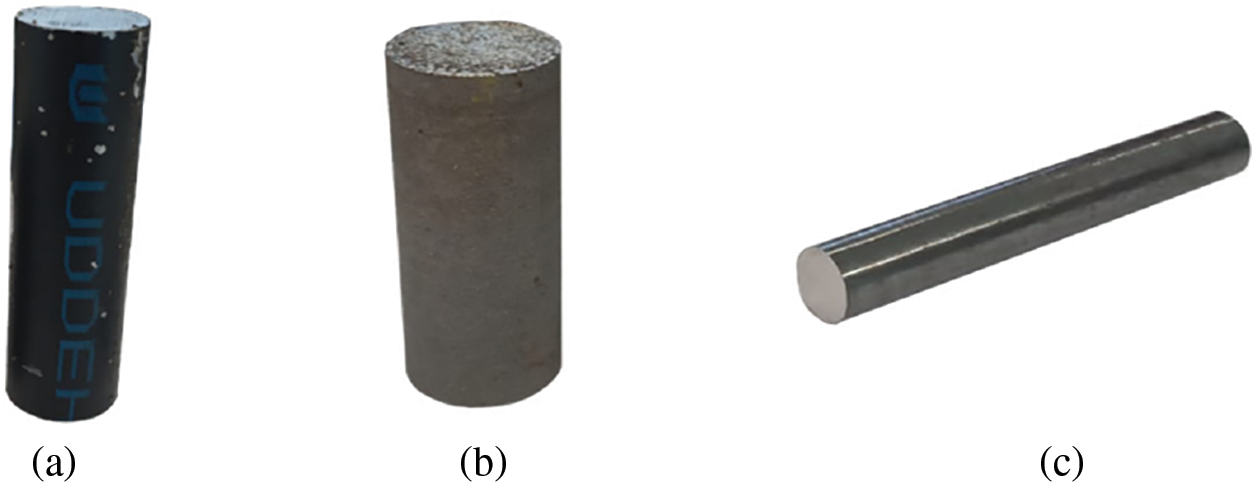
Figure 1: Workpieces used for testing: (a) SLM state; (b) Conv state; (c) state after rotary swaging of Dievar alloy
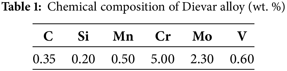
The Conv state was soft annealed at 850°C for two hours, then cooled to 600°C at 10°C/s, and subsequently air-cooled. The chemical composition of the Dievar material is given in Table 1. The as-printed sample for experiment was prepared by SLM as was mentioned above using a Renishaw AM400 printer (Renishaw plc., Wooton-under-Edge, UK) featured particle size ranging from 15 to 45 µm. The powder was melted by laser with a power of 165 W. As an atmosphere was used inherent gas Argon with purity 5.0. The parameters used to build the workpiece were of a layer thickness of 60 µm, a focus size of 70 µm, and a scanning speed of 650 mm’s−1. The SLM workpiece was built with the perpendicular to the building substrate (print orientation 90°) from left to right using the chessboard printing strategy.
Both states were also subjected to plastic deformation via rotary swaging (RS) (Fig. 1c) to enable microstructural comparison of the undeformed and deformed states. After RS, the Conv and SLM states are called Conv+RS and SLM+RS, respectively. The samples were preheated before swaging at the temperature of 900°C. The swaging was performed in two individual swaging passes from the original diameter of 25.4 mm to the final swaged diameter of 10 mm. The swaging ratios after each swaging pass were calculated via Eq. (1):
In Eq. (1), Si (mm2), Sn (mm2) and
The microstructure was observed by JEOL JSM-6010PLUS/LA (JEOL Ltd., Tokyo, Japan) scanning electron microscopy (SEM) equipment available at Swansea University, laboratory MACH 1 and Zeiss EVO LS25 (TESCAN, Brno, Czech Republic) equipment available in Swansea University. Microstructure analysis was focused on observing the differences between prepared states, i.e., Conv, Conv+RS, SLM and SLM+RS. The samples were mechanically ground on SiC papers and subsequently polished (Metalco s.r.o., Roztoky u Prahy, Czech Republic). Nital’s etchant (Metalco s.r.o., Roztoky u Prahy, Czech Republic) was used for visualization of microstructure using SEM microscopy.
2.3 Building the Material Flow Stress Model
To prepare the FEM simulation of hot RS of the Dievar alloy, it is essential to determine the material’s behavior during deformation under various thermomechanical conditions. Since the flow stress behavior has not yet been established for this type of material, uniaxial hot compression tests have been employed. These tests were carried out using the Gleeble 3800-GTC (Dynamic Systems, New York, NY, USA) thermomechanical simulator and its Hydrawedge II testing unit. The tests were conducted at strain rates of 0.1 and 10 s−1 and deformation temperatures of 600°C, 700°C, 800°C, and 900°C. The flow stress behavior under these conditions was measured for both initial states of the Dievar alloy, i.e., the Conv produced alloy and the 3D printed alloy. The testing was performed on cylindrical compression test samples with a diameter of 11 mm and a length of 16 mm, which were always heated directly to a selected deformation temperature by a heating rate of 10°C·s−1 via a direct electric resistance heating with a following soak time of 300 s. Preheated samples were compressed to a true strain of −1.1 and air-quenched for 60 s to preserve the deformation structure. The temperature measurement was provided via a pair of thermocouple wires of K-type (i.e., Ni-Cr (+) and Ni-Al (−)) welded on the sample surface at its mid-length. Tantalum foils and nickel-based grease (high temperature resistance, anti-seize and lubricating compound) were used to protect tungsten carbide anvils and reduce friction forces on the anvils–sample interface. Testing chamber was during the test held under vacuum to hamper oxidation processes, when the vacuum level was below 10−2 Torr-evoked by a rotary vacuum pump.
The load forces measured by the load cell and the values of the anvil displacement measured using a linear variable differential transformer transducer were then used to construct the dependence of the true flow stress behavior on the true strain under a given combination of strain rate and temperature as follows [50]:
In Eqs. (2) and (3), d0 (mm), l0 (mm), Δl (mm), F (N), ε (-) and σ (MPa) embody the initial sample diameter, initial sample length, anvil displacement, load force, true strain and true flow stress, respectively [50].
Once the experimental flow stress curves are known, it is possible to use these data to build a material flow stress model. Due to this model, it is then possible to predict the flow stress behavior for the given material even in experimentally unexamined thermomechanical conditions, which is an important factor from the viewpoint of the subsequent simulations. The intended simulations of the RS process will be performed in the Forge N × T software, and although the material model can be constituted in several ways [51–54], the Hensel-Spittel rheological law relationship (4) has been chosen for this purpose [55]:
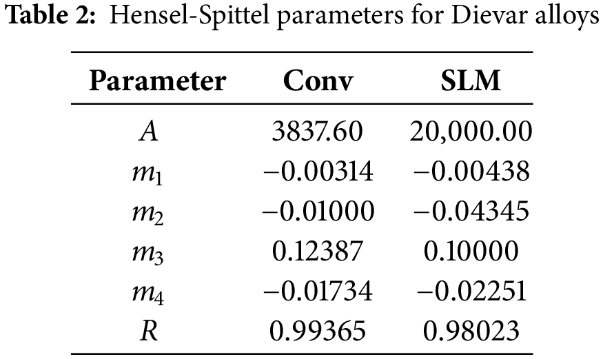
In Eq. (4), T (°C) and ε. (s−1) correspond to the deformation temperature and strain rate, respectively. Parameters A, m1, m2, m3 and m4 which define a specific material have been computed by non-linear regression analysis using the Levenberg-Marquardt optimization algorithm. The algorithm used is an iterative refinement of a rough parameter estimate based on the following formulae [55]:
In this equation, βi, βi+1, ∇βF, H and λ represent an m × 1 vector of material parameters from previous iteration step, an m × 1 vector of material parameters from the current iteration step, an m × 1 vector of gradients of objective function (sum of squared errors), m × m Hessian matrix of the second-order partial derivatives (given as multiplication of m × n transposed Jacobian matrix and n × m Jacobian matrix of partial derivatives of the objective function with respect to the examined material parameters) and damping factor, respectively, where n is the number of observations and m is the number of material parameters [55]. Table 2 summarizes the Hensel-Spittel parameters for Dievar alloys, including Pearson’s correlation coefficient R (-), indicating high regression accuracy for both models.
In spite of the fact that two strain rates were tested, all the acquired results exhibited comparable trends, i.e., higher values of true stress under higher strain rates and lower temperatures. Therefore, for the following analyses, only the strain rate of 0.1 s−1 was selected, being a reliable representative of the acquired data. Fig. 2 shows a comparison between the hot compression test flow stress data and flow stress data calculated via Eq. (4) and parameters in Table 2. The graphical comparison practically confirms the accuracy of the constitutive material model in the case of Dievar produced by Conv way. However, the situation is different in the case of the sample fabricated by additive manufacturing in Fig. 2b. For temperatures of 600°C, 700°C, and 900°C, the experimentally obtained curves correlate relatively well with the Hensel-Spittel model. The difference, at 800°C, is very significant, especially when compared to the Conv state. Regarding material behavior there is a high probability that processes such as work hardening due to martensitic transformation occurred. This hypothesis is supported by the fact that the model overestimated flow stress in comparison to experimental plastometric testing. In other words, based on model prediction, the applied temperature of 800°C is not high enough to provoke a greater extent of material softening by the activation of the recovery or recrystallization process. This overestimation is, with high probability, connected with the fact that the used model does not take into account the possible mutual influence of residual stress and porosity level after 3D printing. As can be seen, during higher strain rate model predicts much closer correlation to experimentally measured flow stress (Fig. 2c). Moreover, a significant difference in the effect of the deformation temperature is evident from this graphical comparison. For both alloys, it can be seen that the flow stress gradually grows as the deformation temperature decreases, but in the case of the alloy manufactured by the 3D printing technology, this increase is more significant—practically, there is an unexpected change when the temperature drops to 700°C and 600°C. At a temperature of 600°C, the flow stress of the 3D printed Dievar was, even so, excessive that the testing device was unable to produce the force required to fully compress the test sample—the registered forces reached the limit of the testing device, i.e., 196 kN. For this reason, there is no recording of the corresponding flow curve for deformations higher than 0.8, and the given missing piece of this curve can only be calculated using the assembled material model.
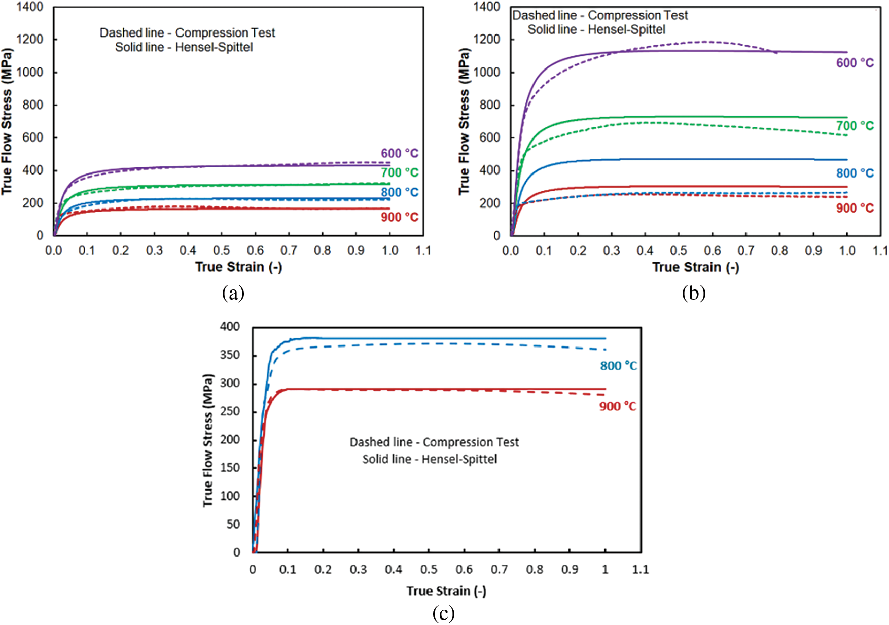
Figure 2: Comparison between the compression test and Hensel-Spittel flow stress data of the investigated Dievar alloys: (a) Conv—0.1 s−1; (b) 3D—0.1 s−1; (c) 3D—10 s−1
Since the hydrostatic stress has a significant effect on the stress-strain relationships in compression tests, it has been examined in Fig. 3, where the initial increase and subsequent decrease due to plastic flow of the material can be observed. This situation was evaluated in 4 chosen sensors as can be seen in Fig. 3b and the results from the sensor can be observed in the graph in Fig. 3c,d, respectively.
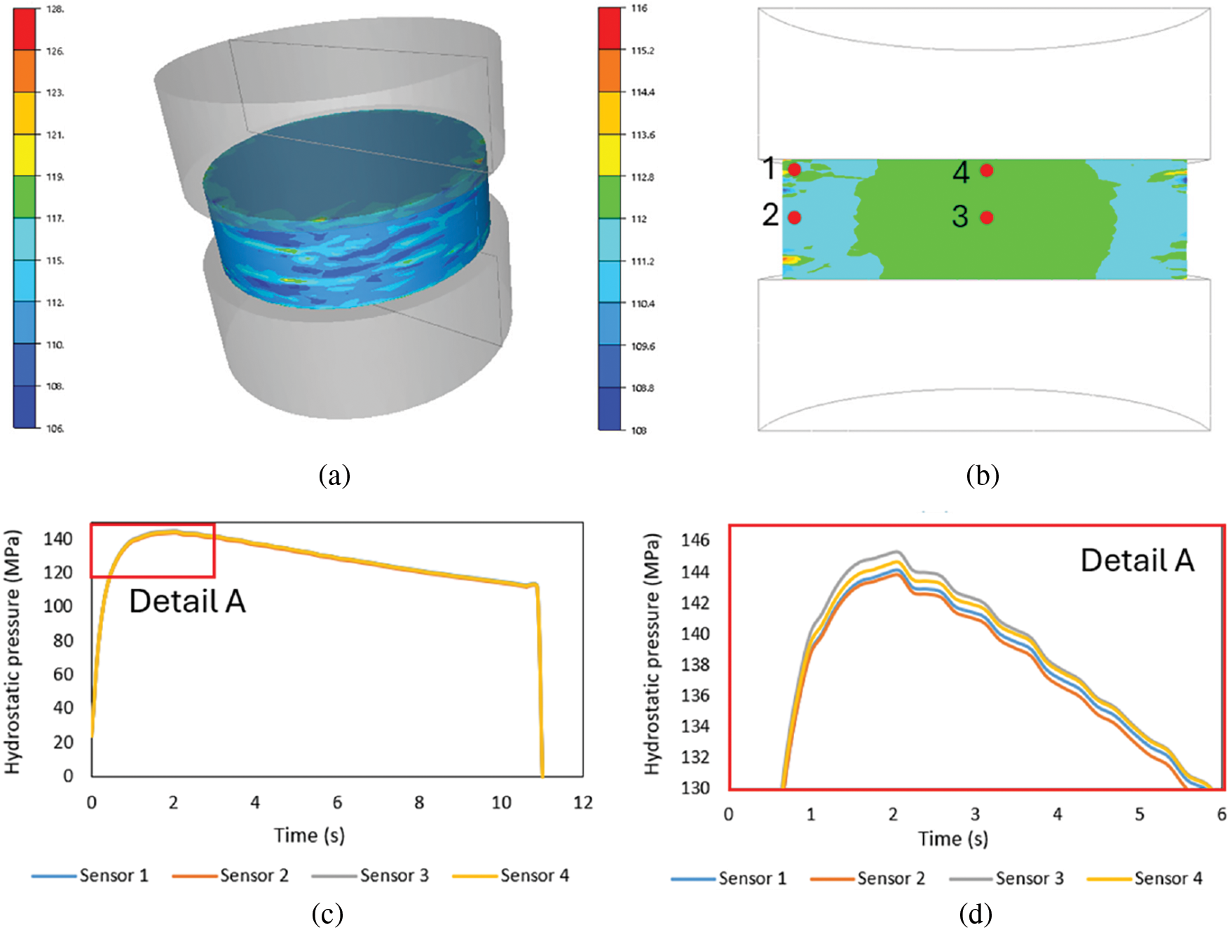
Figure 3: Evaluation of hydrostatic pressure: (a) hydrostatic pressure distribution of the tested sample (MPa); (b) distribution of hydrostatic pressure and sensors in the cross-section (MPa); (c) graphical interpretation of hydrostatic pressure according to sensors; (d) magnification of peaks with differences in hydrostatics pressure value according to the sensors
The selection of the Hensel-Spittel model was based on its ability to effectively describe viscoelastoplastic behavior under hot forming conditions. The model is widely recognized for its flexibility and robustness in capturing the temperature- and strain rate-dependent deformation behavior of metals, making it particularly suitable for high-temperature processes such as RS. Key parameters such as temperature (T) and strain rate (ε.) enable predictions of material behavior even under conditions that do not directly match experimental data obtained at a constant strain rate.
Additionally, the Hensel-Spittel model is one of the most widely used models in industrial practice for simulating the plastic behavior of materials. Its simplicity in implementation and ability to describe material behavior have made it a standard choice in commercial software tools for modeling processes such as hot forming. This widespread adoption in industry confirms its effectiveness and reliability in predicting the mechanical properties of metallic materials.
The deformation behaviour of the investigated alloys under the hot RS procedure was determined by numerical simulation using Forge N × T 3.0 software. Fig. 4 shows a RS geometry before the forming process (red—Dievar rod, green—anvils) with a demonstration of used meshing settings. Swaged rods were heated to 900°C, with anvils and ambient temperature set to 20°C. Other boundary conditions were then set as follows: thermal exchange between anvils and swaged rod was given by a transfer coefficient of 10,000 W·m−2·K−1, thermal exchange between objects and surroundings set as exchange with air (10 W·m−2·K−1), the friction conditions between the tools and the rod were set as without lubricant (corresponds to a friction coefficient of 0.4).
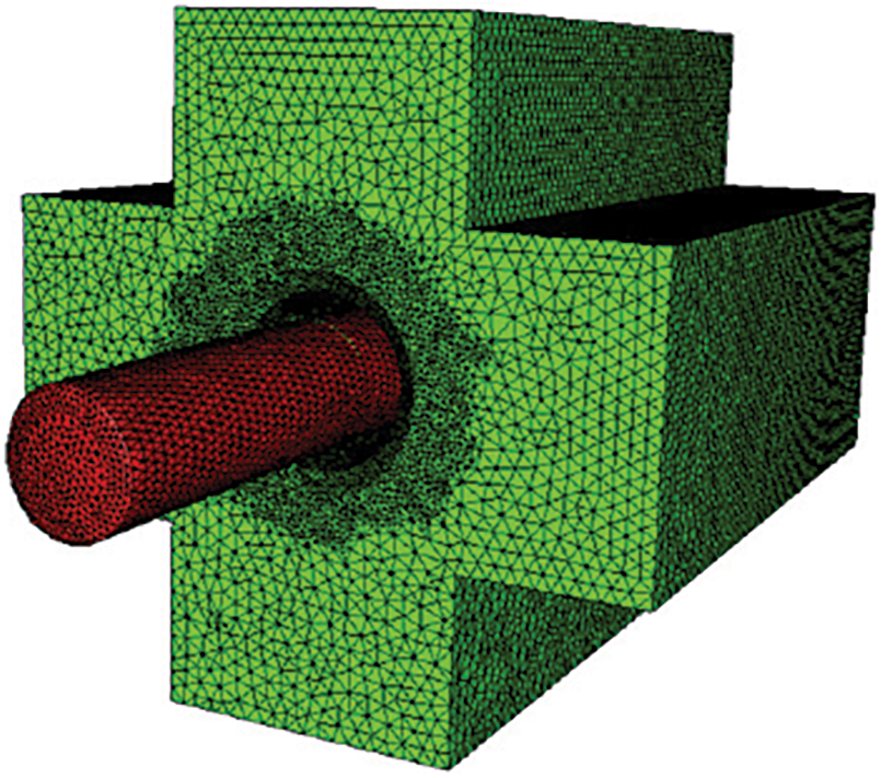
Figure 4: RS process
Note, both investigated material states (Conv and SLM) were processed via two RS passes, which corresponds to two levels of swaging ratios—specifically to
To better understand the swaging process, stress, temperature, and strain distributions were evaluated over time using a moving sensor measurement. It was assessment stress, temperature and strain during the swaging process using a moving sensor measurement. There were placed three sensors on the swaged rod (billet) surface (hereinafter called surface), within 1/4 of the middle (hereinafter called middle) and in the axis of billet (hereinafter called core). The location of the sensors and movement of the billet during the time can be seen in Fig. 5a–h. Furthermore, the overall force exerted by one swaging die during the process was observed. Since the RS technology is symmetrical, the forces on each swaging die are also symmetrical, i.e., the same force is applied to all four swaging dies.
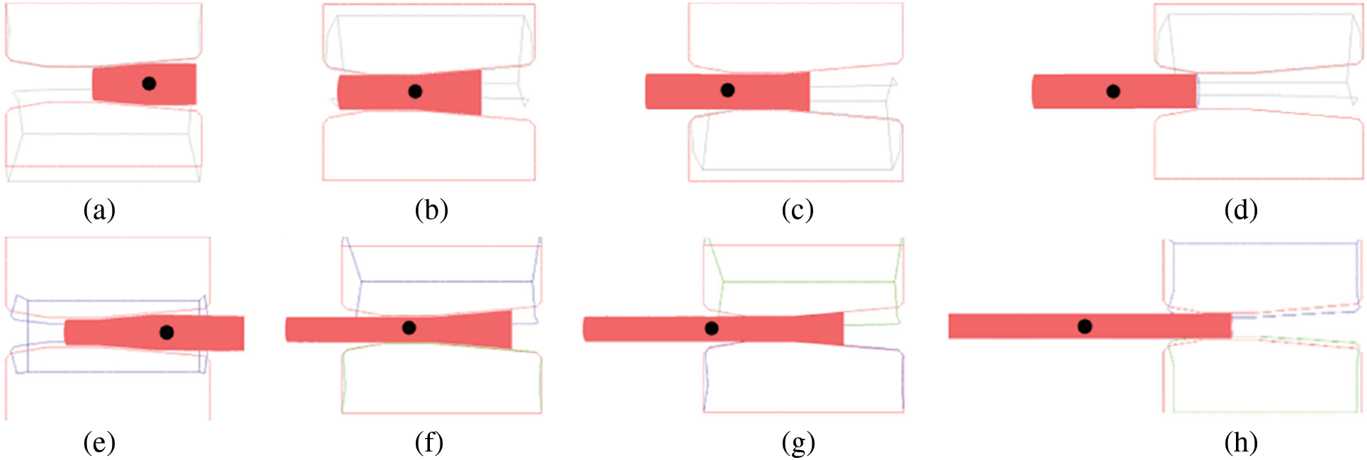
Figure 5: Position of billet during the RS in time (s): (a) 0.5; (b) 1.25; (c) 1.75; (d) 2.75; (e) 0.75; (f) 1.75; (g) 2.25; (h) 3.25
The simulations were conducted using a quasi-static implicit formulation available in the Forge N × T 3.0 software. This approach is well-suited for processes such as RS, where the kinetic energy is negligible compared to internal energy. By employing this method, the influence of kinetic phenomena was minimized, and consequently, it was not necessary for the kinetic-to-internal energy ratio to be monitored or for mass scaling to be applied. The mesh size was selected through an iterative approach to ensure the stability and accuracy of the simulations, with a finer mesh being applied in critical regions characterized by high stress and strain gradients, as illustrated in Fig. 4. In future analyses, a formal convergence study could be included to further refine the results.
Although it is recognized that axi-symmetric analysis could provide faster computational performance, a 3D finite element model was selected. This approach provides a more universal framework that can be easily adapted to potential future analyses involving non-axisymmetric features, variable boundary conditions, or local deviations. The use of the 3D model also enables the preparation of the analysis for future comparisons with experimental data, which often include real-world deviations that axisymmetric analysis may not adequately capture.
3.1 Microstructure Evaluation Using SEM Microscopy
Fig. 6a–d shows the individual microstructures of the prepared states. The microstructure of Conv state had a ferritic-perlite structure with a disperse distribution of carbides throughout the structure. The grain size was approximately 10 to 20 µm and can be seen in Fig. 6a. The microstructure produced by SLM consisted of a cellular structure where the size of the cell was approximately 3 to 5 µm (Fig. 6b). This type of structure is typical from workpiece performed using SLM technology [56–58]. The SLM-prepared structure (Fig. 6b) is visibly finer than the Conv-prepared structure (Fig. 6a).
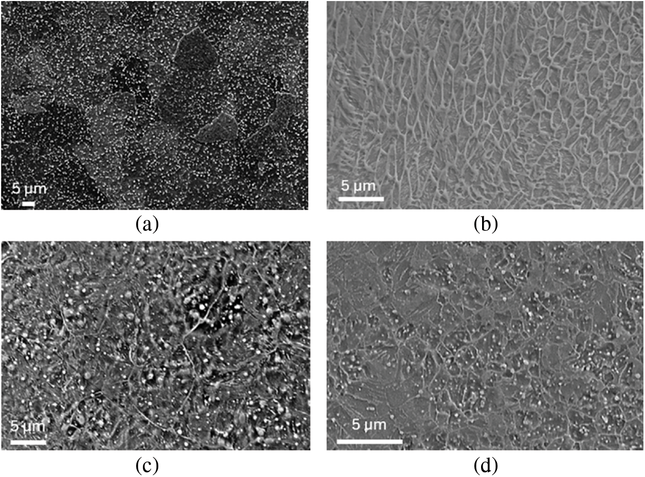
Figure 6: Microstructure at the swaging ratio
After the RS of Conv state, microstructure was composed of finer grains than before RS with a grain size of 5 to 8 µm. Furthermore, the microstructure contained the highest amount of precipitated carbides formed during the RS (Fig. 6c) [5]. The microstructure of the SLM+RS state looked very similar to the Conv+RS state, but the grain size was between 2 and 3 µm with very finely dispersed precipitates (Fig. 6d). From a view point of microstructural, the SLM+RS state after the swaging process shows a finer microstructure, than the Conv state after the RS.
3.2 Influence of RS Procedure on Stress Evolution
The size and distribution of the stress during the RS process can be seen in Fig. 7a–d. The most significant increase in the stress occurred when the billet was inserted into the anvils and during the RS process itself, particularly during the reduction of the billet—see Fig. 7a (between 0.5 and 1.25 s), Fig. 7b (between 0.5 and 1.5 s), and Fig. 7c,d (between 0.5 and 1.75 s). In all states, the highest stress values were measured on the surface (Fig. 7a–d). The direct contact between the anvils and the billet is the reason for the higher stresses on the surface and its surroundings. The trends of stresses in the middle area are very similar to the billet core for all swaged samples (Fig. 7a–d). When comparing stress values, there were a significant difference between the Conv state with a swaging ratio of
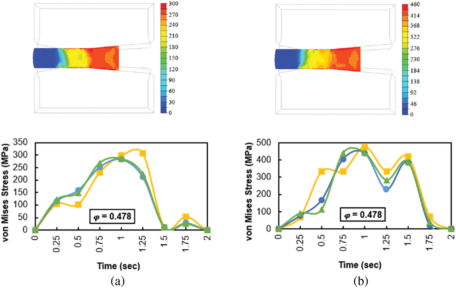
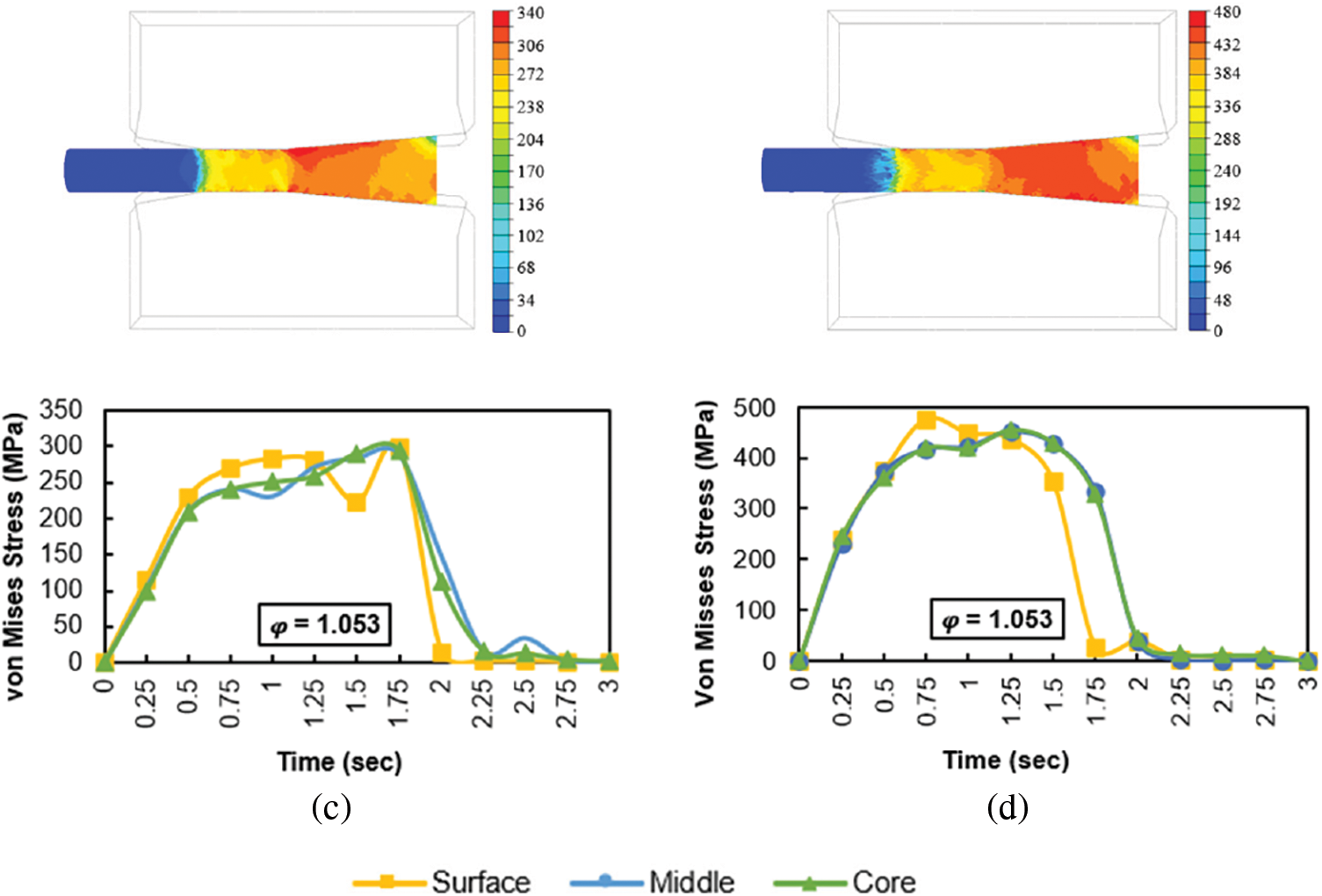
Figure 7: Stress-time dependence of RS Dievar alloy: (a) first pass Conv; (b) first pass SLM; (c) second pass Conv; (d) second pass SLM
3.3 Influence of RS Procedure on Temperature Evolution
Regarding the temperature evolution is concerned, it can be observed that the temperature in the first moments of the swaging process first rises slowly and then rises steeply—practically independently of the technology of preparation of the examined material (Fig. 8). In the case of the first pass, this initial increase is completed in approximately 1.2 s. However, looking at the temperature recorded on the surface of the deformed billet, it can be seen that in the first few passes, the aforementioned steep rise in temperature is preceded by a drop in temperature—this is even very significant in the case of the Conv prepared alloy (Fig. 8a). The temperature difference between the billet surface and core is due to heat dissipation to the cold anvils. The phase of sharp increase is then evidently caused by the development of deformation heat, which can also compensate the heat transfer to the anvils. For the second pass, it can be seen that in this case the temperature drop in the surface layers is negligible or absent. The thinner rod allows faster temperature equalization between its center and surface. The graphic records also show a temperature drop, immediately following the phase of rapid temperature growth. This drop corresponds to the moment when the bar (or more precisely the part of it fitted with sensors) leaves the deformation zone. The heat is dissipated into the surroundings as the deformation heat from the deformed part spreads to the part that is no longer deformed.
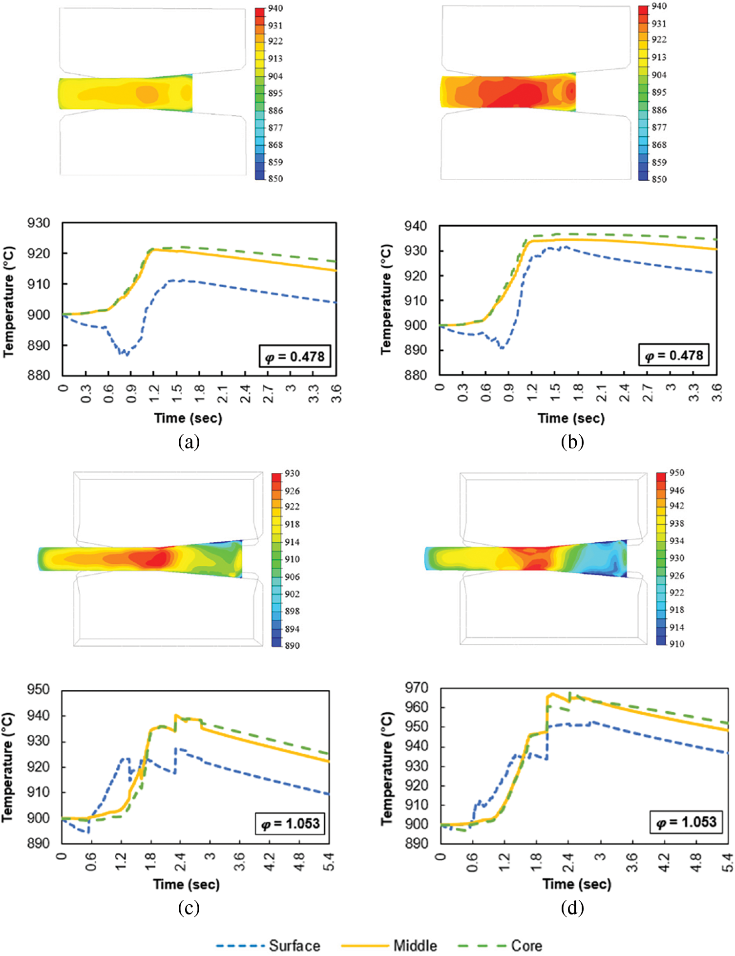
Figure 8: Temperature-time dependence of RS Dievar alloy: (a) first pass Conv; (b) first pass SLM; (c) second pass Conv; (d) second pass SLM
3.4 Influence of RS Procedure on Imposed Strain
During the RS procedure, strain is gradually imposed into the formed part. The graph in Fig. 9 show that this accumulation of strain occurs gradually over time. The strain initially increases very slowly, which corresponds to the part of the billet that is just approaching the main part of the deformation band (just approaching between the anvils). The part of the billet monitored by the sensors is not yet directly deformed by the tools, but as a result of the deformation of the surrounding parts that are already between the anvils, a partial deformation also occurs here as well, and this deformation is the greater the closer the given part of the billet is to the anvils. As soon as the monitored part of the billet gets between the anvils, there will be an intensive increase in strain—practically in all its layers. The most intensive stresses occur in the surface layers, directly in contact with the anvils, aligning with the previously observed stress distribution trends. As soon as the deformed part of the billet leaves the space of the anvils, the strain value no longer increases and the curve changes to a constant character—the imposed strain remains in the material. It is also interesting to note the difference in the imposed strain on the surface during the first pass, at a swaging ratio of 0.478. The imposed strain on the surface of the additively manufactured state reaches a value of 1, while in the case of the Conv state it reaches a value of 0.8. This difference in imposed strain is a consequence of the relatively high porosity of the SLM sample, which achieves 13%. Therefore, in the first pass, the imposed strain must be used to eliminate the pores and subsequently the imposed strain follows the same behaviour as in the case of the Conv sample. As for the second pass, the newly imposed strain begins to be added to the strain accumulated from the previous pass. It can be noticed that on the surface of the billet in the first pass the strain of 0.8 and 1 have been accumulated as for the Conv and SLM material, respectively and the next strain begins to accumulate on these strain values. Similar behavior can be then observed for the inner layers of the billet.
Figure 9: Imposed strain-time dependence of RS Dievar alloy: (a) first pass Conv; (b) first pass SLM; (c) second pass Conv; (d) second pass SLM
Fig. 10 shows the evolution of forces recorded on the first anvil. It can be seen that the trend is more or less the same regardless of the pass or the material forged. For the first pass (corresponding to a swaging ration of 0.478), a steep increase in force and a significant peak followed by a steep decline can be observed. All this takes place in a very short moment, lasting about 2 s, during which the billet is swaged. The force gradually increases as more and more of the billet passes between the anvils. When about half of the billet has been swaged, the force reaches its maximum and begins to decrease again when forging the second half of the billet. The same situation is observed in the case of the second pass (where the swaging ratio of 1.053 was applied). The difference compared to the first pass is essentially a much slower ramp-up of force in the initial forging phase. The peaks are also shifted to longer times. This is also because the rod is already longer during the second pass, and it’s swaging therefore takes a longer time. However, another very important fact is revealed by the graphic comparison, namely that the forces recorded during the swaging of material produced by the SLM technique are always higher than the forces recorded during the swaging of Dievar alloy produced conventionally. This is in accordance with the fact that the material produced by the SLM process has a higher flow stress behavior compared to the conventional one (see comparison in Fig. 2)—therefore, greater forces must be applied to change the shape.
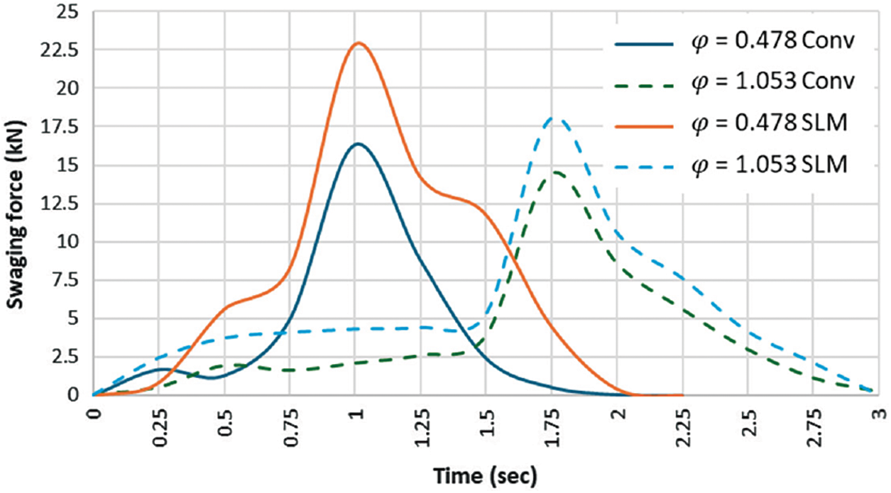
Figure 10: First anvil forces response
The Hensel-Spittel model was chosen for its established ability to describe viscoelastoplastic behavior under hot forming conditions and its flexibility in incorporating temperature and strain rate dependencies. This model has proven robust for industrial applications and provides a reliable framework for simulating processes such as RS. Despite these strengths, certain discrepancies were observed between the theoretical predictions and experimental data, particularly for 3D-printed metals at higher temperatures and larger strains.
These deviations may arise from the unique microstructural characteristics of 3D-printed materials, such as porosity and anisotropy, which the Hensel-Spittel model does not explicitly account for. However, the model was selected as a practical and effective tool for capturing the general material behavior under the studied conditions. Its widespread industrial adoption further supports its suitability for this type of analysis. Future studies could focus on integrating more advanced constitutive models to better address the specific properties of 3D-printed materials, particularly under extreme conditions.
The paper deals with the FEM simulation of RS of Dievar alloy produced by additive manufacturing technology Selective Laser Melting (SLM) and ingot casting (Conv).
For the simulation, true-flow-stress to strain curves were determined at temperatures between 600°C and 900°C and a so-called Hensel-Spittel model was constructed, which was the input for the rotary swaging FEM simulation.
Before RS, the Conv-prepared state had a yield strength of 380 MPa and the additively manufactured SLM state had a yield strength of 1100 MPa.
After RS, the SLM state exhibits a finer microstructure compared to the Conv state.
The microstructure of the SLM state after RS shows a finer microstructure than the microstructure of the Conv state after RS. Specifically, the grain size of the Conv+RS condition was 5 to 8 µm and that of the SLM+RS condition was 2 to 3 µm.
The highest stress during swaging was observed at the input billet between the anvils. For the Conv and SLM states, the stresses during the first pass were 300 and 460 MPa, respectively. In the second pass, the stresses increased to 340 MPa for the Conv state and 480 MPa for the SLM state.
At the surface, the sample temperature initially decreases due to heat transfer between the preheated sample and the cold anvils. However, as plastic deformation occurs between the anvils, the temperature of the sample (surface, middle, and core) begins to rise.
During the first pass, the temperature increased by 25°C for the Conv+RS sample and 35°C for the SLM+RS sample. In the second pass, the temperature rose further by approximately 15°C, reaching 940°C for the Conv+RS sample, and by 30°C, reaching 970°C for the SLM+RS sample.
The simulation results show that the imposed strain is highest at the surface and increases as the overall strain magnitude increases. In the middle and core of the sample, the strain distribution remains almost identical.
For the first pass, the imposed strain at the surface is 0.8 for the Conv+RS sample and 1.0 for the SLM+RS sample. This difference in imposed strain is a consequence of the relatively high porosity of the SLM sample, which achieves 13%. Therefore, in the first pass, the imposed strain must be used to eliminate the pores and subsequently the imposed strain follows the same behaviour as in the case of the Conv sample. During the second pass, the imposed strain at the surface reaches 2.3 for both the Conv+RS and SLM+RS samples.
The swaging forces were assessed for two swaging ratios: 0.478 during the first pass and 1.053 during the second pass. It can be seen that less force is required to produce the Conv state, than SLM state. The force required for forging decreases as the number of forges increases from viewpoint of the observed trend.
The Hensel-Spittel model, while effective for capturing temperature- and strain-rate-dependent behavior, does not explicitly account for microstructural anisotropy and porosity, particularly in 3D-printed materials, which may influence the correlation between experimental and modeled data at lower temperatures.
The results of this study provide valuable insights into the viscoelastoplastic behavior of Dievar alloy under conditions relevant to RS. This alloy is widely used in the production of dies for high-pressure die casting, forging tools, and other equipment utilized in the automotive and aerospace industries. Its exceptional thermal stability, wear resistance, and high strength make it suitable for applications where the material is subjected to a combination of extreme temperatures, mechanical loads, and cyclic deformation. This knowledge is helping to optimise forming processes and improve the performance of components made from this alloy.
Acknowledgement: We acknowledge Swansea University, laboratory MACH1 for observation of SEM microstructure. The cooperation of Dr. Josef Walek (VŠB–Technical University of Ostrava), is greatly appreciated and the project TQ03000386 Optimization of Technological Parameters of Electro Slag Remelting of Steels for Special Applications co-financed by the state budget by the Technology agency of the Czech Republic under the SIGMA Program.
Funding Statement: This research was funded by the project SP2024/089 of the Specific Research of the VŠB-Technical University of Ostrava and realized within the framework of the Johannes Amos Comenius Program, Materials and Technologies for Sustainable Development—MATUR, No. CZ.02.01.01/00/22_008/0004631 and Brno University of Technology project No. FSI-S-23-8231 “Investigation of Dynamic Deformation Behavior of Metallic Materials Prepared via Alternative Production Methods”.
Author Contributions: The authors confirm contribution to the paper as follows: study conception and design: Josef Izák, Marek Benč, Petr Opěla; data collection: Josef Izák, Marek Benč, Petr Opěla; analysis and interpretation of results: Josef Izák, Marek Benč, Petr Opěla; draft manuscript preparation: Josef Izák. All authors reviewed the results and approved the final version of the manuscript.
Availability of Data and Materials: The data that support the findings of this study are available from the corresponding author, JI, upon reasonable request.
Ethics Approval: Not applicable.
Conflicts of Interest: The authors declare no conflicts of interest to report regarding the present study.
References
1. Macháčková A, Kocich R, Bojko M, Kunčická L, Polko K. Numerical and experimental investigation of flue gases heat recovery via condensing heat exchanger. Int J Heat Mass Transf. 2018;124:1321–33. doi:10.1016/j.ijheatmasstransfer.2018.04.051. [Google Scholar] [CrossRef]
2. Zhitelev PS, Adigamov RR, Glukhov PA, Sokolov SF, Golubkov NA. Investigation of the recovery process during continuous annealing of cold-rolled automotive steels. Metallurgist. 2024;67(9–10):1351–61. doi:10.1007/s11015-024-01627-3. [Google Scholar] [CrossRef]
3. Kocich R, Kunčická L, Benč M, Weiser A, Németh G. Corrosion behavior of selective laser melting-manufactured bio-applicable 316L stainless steel in ionized simulated body fluid. Int J Bioprinting. 2024;10(1):339–56. doi:10.36922/ijb.1416. [Google Scholar] [CrossRef]
4. Xie Y, Cheng X, Wei J, Luo R. Characterization of carbide precipitation during tempering for quenched dievar steel. Materials. 2022;15(18):6448. doi:10.3390/ma15186448. [Google Scholar] [PubMed] [CrossRef]
5. Izák J, Benč M, Kunčická L, Opěla P, Kocich R. Influence of imposed strain on weldability of dievar alloy. Materials. 2024;17(10):2317. doi:10.3390/ma17102317. [Google Scholar] [PubMed] [CrossRef]
6. Machado AR, da Silva LRR, Pimenov DY, de Souza FCR, Kuntoğlu M, de Paiva RL. Comprehensive review of advanced methods for improving the parameters of machining steels. J Manuf Process. 2024;125:111–42. doi:10.1016/j.jmapro.2024.07.044. [Google Scholar] [CrossRef]
7. Izák J, Strunz P, Levytska O, Neméth G, Šaroun J, Pagáč M, et al. Residual stress distribution in dievar tool steel bars produced by conventional additive manufacturing and rotary swaging processes. Materials. 2024;17(23):5706. doi:10.3390/ma17235706. [Google Scholar] [PubMed] [CrossRef]
8. Khan MAA, Sheikh AK. A comparative study of simulation software for modelling metal casting processes. Int J Simul Model. 2018;17(2):197–209. doi:10.2507/IJSIMM17(2)402. [Google Scholar] [CrossRef]
9. Lopez PER, Jalali PN, Sjöström U, Jönsson PG, Mills KC, Sohn I. Key lubrication concepts to understand the role of flow, heat transfer and solidification for modelling defect formation during continuous casting. ISIJ Int. 2018;58(2):201–10. doi:10.2355/isijinternational.ISIJINT-2017-482. [Google Scholar] [CrossRef]
10. Kunčická L, Kocich R. Optimizing electric conductivity of innovative Al-Cu laminated composites via thermomechanical treatment. Mater Design. 2022;215:110441. doi:10.1016/j.matdes.2022.110441. [Google Scholar] [CrossRef]
11. Strunz P, Kocich R, Canelo-yubero D, Macháčková A, Beran P, Krátká L. Texture and differential stress development in W/Ni-Co composite after rotary swaging. Materials. 2020;13(12):2869. doi:10.3390/ma13122869. [Google Scholar] [PubMed] [CrossRef]
12. Tusher MMH, Ince A, Neu RW. High cycle fatigue and very high cycle fatigue performance of selective laser melting Ti-6Al-4V Titanium Alloy—a review. Mater Perform Charact. 2023;12(2):214–93. doi:10.1520/MPC20220088. [Google Scholar] [CrossRef]
13. Aboulkhair NT, Simonelli M, Parry L, Ashcroft I, Tuck C, Hague R. 3D printing of Aluminium alloys: additive manufacturing of Aluminium alloys using selective laser melting. Prog Mater Sci. 2019;106:100578. doi:10.1016/j.pmatsci.2019.100578. [Google Scholar] [CrossRef]
14. Dolzhenko P, Odnobokova M, Tikhonova M, Kaibyshev R, Chowdhury SG, Belyakov A. Grain boundary assembly in a 316L steel produced by selective laser melting and annealing. Mater Charact. 2023;206:113434. doi:10.1016/j.matchar.2023.113434. [Google Scholar] [CrossRef]
15. Chen X, Liu K, Guo W, Gangil N, Siddiquee AN, Konovalov S. The fabrication of NiTi shape memory alloy by selective laser melting: a review. Rapid Prototyp J. 2019;25(8):1421–32. doi:10.1108/RPJ-11-2018-0292. [Google Scholar] [CrossRef]
16. Pimenov DY, Berti LF, Pintaude G, Peres GX, Chaurasia Y, Khanna N, et al. Influence of selective laser melting process parameters on the surface integrity of difficult-to-cut alloys: comprehensive review and future prospects. Int J Adv Manuf Technol. 2023;127(3–4):1071–102. doi:10.1007/s00170-023-11541-8. [Google Scholar] [CrossRef]
17. Kořínek M, Halama R, Fojtík F, Pagáč M, Krček J, Krzikalla D, et al. Monotonic tension-torsion experiments and fe modeling on notched specimens produced by slm technology from ss316l. Materials. 2020;14(1):1–15. doi:10.3390/ma14010033. [Google Scholar] [PubMed] [CrossRef]
18. Hosseinzadeh A, Radi A, Richter J, Wegener T, Sajadifar SV, Niendorf T, et al. Severe plastic deformation as a processing tool for strengthening of additive manufactured alloys. J Manuf Process. 2021;68:788–95. doi:10.1016/j.jmapro.2021.05.070. [Google Scholar] [CrossRef]
19. Kunčická L, Kocich R, Benč M, Dvořák J. Affecting microstructure and properties of additively manufactured AISI 316L steel by rotary swaging. Materials. 2022;15(18):6291. doi:10.3390/ma15186291. [Google Scholar] [PubMed] [CrossRef]
20. Pustovoytov D, Pesin A, Tandon P. Asymmetric (hot, warm, cold, cryo) rolling of light alloys: a review. Metals. 2021;11(6):956. doi:10.3390/met11060956. [Google Scholar] [CrossRef]
21. Kudrya AV, Sokolovskaya EA, Ngo KN, Kaikibaeva AS. Relation between the nonuniformity of the properties and the structure of large forgings. Russian Metall Met. 2018;2018(6):589–92. doi:10.1134/S0036029518060125. [Google Scholar] [CrossRef]
22. Xu Q, Zhu J, Zong Y, Liu L, Zhu X, Zhang F, et al. Effect of drawing and annealing on the microstructure and mechanical properties of 304 austenitic stainless steel wire. Mater Res Express. 2021;8(12):126530. doi:10.1088/2053-1591/ac44d6. [Google Scholar] [CrossRef]
23. Wang Z, Chen J, Kocich R, Tardif S, Dolbnya IP, Kunčická L, et al. Grain structure engineering of NiTi shape memory alloys by intensive plastic deformation. ACS Appl Mater Interfaces. 2022;14(27):31396–410. doi:10.1021/acsami.2c05939. [Google Scholar] [PubMed] [CrossRef]
24. Strunz P, Kunčická L, Beran P, Kocich R, Hervoches C. Correlating microstrain and activated slip systems with mechanical properties within rotary swaged WNiCo pseudoalloy. Materials. 2020;13(1):208. doi:10.3390/ma13010208. [Google Scholar] [PubMed] [CrossRef]
25. Nakao Y, Miura H. Nano-grain evolution in austenitic stainless steel during multi-directional forging. Mater Sci Eng: A. 2011;528(3):1310–7. doi:10.1016/j.msea.2010.10.018. [Google Scholar] [CrossRef]
26. Wu Y, Dong X. Upper bound analysis of forging penetration in a radial forging process. Int J Mech Sci. 2015;103:1–8. doi:10.1016/j.ijmecsci.2015.08.023. [Google Scholar] [CrossRef]
27. Hlaváč LM, Kocich R, Gembalová L, Jonšta P, Hlaváčová IM. AWJ cutting of copper processed by ECAP. Int J Adv Manuf Technol. 2016;86(1–4):885–94. doi:10.1007/s00170-015-8236-2. [Google Scholar] [CrossRef]
28. Kunčická L, Kocich R, Ryukhtin V, Cullen JCT, Lavery NP. Study of structure of naturally aged aluminium after twist channel angular pressing. Mater Charact. 2019;152:94–100. doi:10.1016/j.matchar.2019.03.045. [Google Scholar] [CrossRef]
29. Lukáč P, Kocich R, Greger M, Padalka O, Száraz Z. Microstructure of AZ31 and AZ61 Mg alloys prepared by rolling and ECAP. Kovove Mater-Met Mater. 2007;45(3):115–20. [Google Scholar]
30. Kocich R, Greger M, Kursa M, Szurman I, Macháčková A. Twist channel angular pressing (TCAP) as a method for increasing the efficiency of SPD. Mater Sci Eng: A. 2010;527(23):6386–92. doi:10.1016/j.msea.2010.06.057. [Google Scholar] [CrossRef]
31. Dolzhenko P, Tikhonova M, Odnobokova M, Kaibyshev R, Belyakov A. Ultrafine-grained stainless steels after severe plastic deformation. Metals. 2023;13(4):674. doi:10.3390/met13040674. [Google Scholar] [CrossRef]
32. Kocich R, Kunčická L. Crossing the limits of electric conductivity of copper by inducing nanotwinning via extreme plastic deformation at cryogenic conditions. Mater Charact. 2024;207:113513. doi:10.1016/j.matchar.2023.113513. [Google Scholar] [CrossRef]
33. Wang Z, Zhang Y, Liogas K, Chen J, Vaughan GBM, Kocich R, et al. In situ synchrotron X-ray diffraction analysis of two-way shape memory effect in Nitinol. Mater Sci Eng: A. 2023;878:145226. [Google Scholar]
34. Estrin Y, Martynenko N, Lukyanova E, Serebryany V, Gorshenkov M, Morozov M, et al. Effect of rotary swaging on microstructure, texture, and mechanical properties of a Mg-Al-Zn alloy. Adv Eng Mater. 2020;22(1). doi:10.1002/adem.201900506. [Google Scholar] [CrossRef]
35. Kocich R, Kunčická L. Optimizing structure and properties of Al/Cu laminated conductors via severe shear strain. J Alloys Comp. 2023;953:170124. doi:10.1016/j.jallcom.2023.170124. [Google Scholar] [CrossRef]
36. Kunčická L, Kocich R, Strunz P, Macháčková A. Texture and residual stress within rotary swaged Cu/Al clad composites. Mater Lett. 2018;230:88–91. doi:10.1016/j.matlet.2018.07.085. [Google Scholar] [CrossRef]
37. Panov D, Kudryavtsev E, Naumov S, Klimenko D, Chernichenko R, Mirontsov V, et al. Gradient microstructure and texture formation in a metastable austenitic stainless steel during cold rotary swaging. Materials. 2023;16(4):1706. doi:10.3390/ma16041706. [Google Scholar] [PubMed] [CrossRef]
38. Kunčická L, Kocich R. Effect of activated slip systems on dynamic recrystallization during rotary swaging of electro-conductive Al-Cu composites. Mater Lett. 2022;321:132436. doi:10.1016/j.matlet.2022.132436. [Google Scholar] [CrossRef]
39. Machackova A, Kratka L, Petrmichl R, Kuncicka L, Kocich R. Affecting structure characteristics of rotary swaged tungsten heavy alloy via variable deformation temperature. Materials. 2019;12(24):4200. doi:10.3390/ma12244200. [Google Scholar] [PubMed] [CrossRef]
40. Wang Y, Yang Y, Lin Y, Chen H, Li G, Huang Y, et al. Microstructural refinement and mechanical properties improvement of Mg-Al–Mn-Zn–Ca alloy processed by rotary swaging at room temperature. Mater Sci Eng: A. 2024;913:147014. doi:10.1016/j.msea.2024.147014. [Google Scholar] [CrossRef]
41. Chuvil’deev VN, Murashov AA, Nokhrin AV, Berendeev NN, Likhnitskii CV, Sysoev AN, et al. Effect of annealing on the corrosion-fatigue strength and hot salt corrosion resistance of fine-grained titanium near-α alloy Ti-5Al-2V obtained using Rotary Swaging. J Alloys Comp. 2024;1003:175612. doi:10.1016/j.jallcom.2024.175612. [Google Scholar] [CrossRef]
42. Canelo-Yubero D, Kocich R, Hervoches C, Strunz P, Kunčická L, Krátká L. Neutron diffraction study of residual stresses in a W–Ni–Co heavy alloy processed by rotary swaging at room and high temperatures. Met Mater Int. 2022;28(4):919–30. doi:10.1007/s12540-020-00963-8. [Google Scholar] [CrossRef]
43. Kunčická L, Kocich R, Németh G, Dvořák K, Pagáč M. Effect of post process shear straining on structure and mechanical properties of 316 L stainless steel manufactured via powder bed fusion. Addit Manuf. 2022;59:103128. doi:10.1016/j.addma.2022.103128. [Google Scholar] [CrossRef]
44. Vinogradov A, Estrin Y. Analytical and numerical approaches to modelling severe plastic deformation. Prog Mater Sci. 2018;95:172–242. doi:10.1016/j.pmatsci.2018.02.001. [Google Scholar] [CrossRef]
45. Latypov MI, Alexandrov. Finite element analysis of plastic deformation in twist extrusion. Comput Mater Sci. 2012;60:194–200. doi:10.1016/j.commatsci.2012.03.035. [Google Scholar] [CrossRef]
46. Kocich R, Kursab M, Macháčková A. FEA of plastic flow in AZ63 alloy during ECAP process. Acta Phys Pol A. 2012;122(3):581–7. doi:10.12693/APhysPolA.122.581. [Google Scholar] [CrossRef]
47. Kunčická L, Kocich R, Drápala J, Andreyachshenko VA. FEM simulations and comparison of the ECAP and ECAP-PBP influence on Ti6Al4V alloy’s deformation behaviour. In: METAL 2013-22nd International Conference on Metallurgy and Materials; 2013. p. 391–6. [Google Scholar]
48. Ostapovich KV, Trusov PV, Yants AY. Prediction of crystallographic texture formation in polycrystalline samples under severe plastic deformation based on a two-level statistical elasto-viscoplastic model. Phys Mesomech. 2021; 24(3):225–36. doi:10.1134/S1029959921030012. [Google Scholar] [CrossRef]
49. Kocich R, Greger M, Macháčková A. Finite element investigation of influence of selected factors on ECAP process. In: METAL 2010-19th International Conference on Metallurgy and Materials; 2010. p. 166–71. [Google Scholar]
50. Kocich R, Opěla P, Marek M. Influence of structure development on performance of copper composites processed via intensive plastic deformation. Materials. 2023; 16(13):4780. Switzerland: MDPI AG. doi:10.3390/ma16134780. [Google Scholar] [PubMed] [CrossRef]
51. Savaedi Z, Motallebi R, Mirzadeh H. A review of hot deformation behavior and constitutive models to predict flow stress of high-entropy alloys. J Alloys Comp. 2022;903:163964. doi:10.1016/j.jallcom.2022.163964. [Google Scholar] [CrossRef]
52. Motallebi R, Savaedi Z, Mirzadeh H. Additive manufacturing—a review of hot deformation behavior and constitutive modeling of flow stress. Current Opinion Solid State Mater Sci. 2022;26(3):100992. doi:10.1016/j.cossms.2022.100992. [Google Scholar] [CrossRef]
53. Aghajani Derazkola H, Garcia E, Murillo-Marrodán A, Conde Fernandez A. Review on modeling and simulation of dynamic recrystallization of martensitic stainless steels during bulk hot deformation. J Mater Res Technol. 2022;18:2993–3025. doi:10.1016/j.jmrt.2022.03.179. [Google Scholar] [CrossRef]
54. Opěla P, Schindler I, Kawulok P, Kawulok R, Rusz S, Sauer M. Shallow and deep learning of an artificial neural network model describing a hot flow stress evolution: a comparative study. Mater Design. 2022;220:110880. doi:10.1016/j.matdes.2022.110880. [Google Scholar] [CrossRef]
55. Němec J, Kunčická L, Opěla P, Dvořák K. Determining hot deformation behavior and Rheology laws of selected austenitic stainless steels. Metals. 2023;13(11):1902. doi:10.3390/met13111902. [Google Scholar] [CrossRef]
56. Kahlert M, Brenne F, Vollmer M, Niendorf T. Influence of microstructure and defects on mechanical properties of AISI H13 manufactured by electron beam powder bed fusion. J Mater Eng Perform. 2021;30(9):6895–904. doi:10.1007/s11665-021-06059-7. [Google Scholar] [CrossRef]
57. Yuan M, Cao Y, Karamchedu S, Hosseini S, Yao Y, Berglund J, et al. Characteristics of a modified H13 hot-work tool steel fabricated by means of laser beam powder bed fusion. Mater Sci Eng: A. 2022;831:142322. doi:10.1016/j.msea.2021.142322. [Google Scholar] [CrossRef]
58. Yonehara M, Ttaka I, Nagahama T, Mizoguchi T, Tano M, Yoshimi T, et al. Parameter optimization of the high-power laser powder bed fusion process for H13 tool steel. Int J Adv Manuf Technol. 2020;110(1–2):427–37. doi:10.1007/s00170-020-05879-6. [Google Scholar] [CrossRef]
Cite This Article
 Copyright © 2025 The Author(s). Published by Tech Science Press.
This work is licensed under a Creative Commons Attribution 4.0 International License , which permits unrestricted use, distribution, and reproduction in any medium, provided the original work is properly cited.
 Downloads
 Citation Tools