
 Submit a Paper
 Propose a Special lssue
 Open Access
REVIEW

Smoothed Particle Hydrodynamics (SPH) Simulations of Drop Evaporation: A Comprehensive Overview of Methods and Applications
Departamento de Ciencias Básicas, Universidad Autónoma Metropolitana, Azcapotzalco Campus, Av. San Pablo 420, Colonia Nueva el Rosario, Alcaldía Azcapotzalco, Ciudad de México, 02128, Mexico
* Corresponding Author: Leonardo Di G. Sigalotti. Email:
Computer Modeling in Engineering & Sciences 2025, 142(3), 2281-2337. https://doi.org/10.32604/cmes.2025.060497
Received 03 November 2024; Accepted 23 January 2025; Issue published 03 March 2025
 View Full Text
 Download PDF
Abstract
The evaporation of micrometer and millimeter liquid drops, involving a liquid-to-vapor phase transition accompanied by mass and energy transfer through the liquid-vapor interface, is encountered in many natural and industrial processes as well as in numerous engineering applications. Therefore, understanding and predicting the dynamics of evaporating flows have become of primary importance. Recent efforts have been addressed using the method of Smoothed Particle Hydrodynamics (SPH), which has proven to be very efficient in correctly handling the intrinsic complexity introduced by the multiscale nature of the evaporation process. This paper aims to provide an overview of published work on SPH-based simulations related to the evaporation of drops suspended in static and convective environments and impacting on heated solid surfaces. After a brief theoretical account of the main ingredients necessary for the modeling of drop evaporation, the fundamental aspects of SPH are revisited along with the various existing formulations that have been implemented to address the challenges imposed by the physics of evaporating flows. In the following sections, the paper summarizes the results of SPH-based simulations of drop evaporation and ends with a few comments on the limitations of the current state-of-the-art SPH simulations and future lines of research.Graphic Abstract
Keywords
The evaporation of a liquid is a complex physical process involving the phase transition of the liquid into a vapor state and the motion (and/or deformation) of the liquid-vapor interface. Since mass and energy are transferred simultaneously through the interface, the evaporation is a multiscale and multistep heat transfer problem. The phase transition can take place at different temperatures for which enough thermal energy is stored within the liquid to overcome the forces of surface tension. At the microscopic level, the evaporation occurs when the kinetic energy acquired by the molecules close to the liquid surface is greater than the cohesion exerted by the intermolecular forces within the liquid phase [1,2]. For water drops in warm air, heat is transferred to the drop surface by conduction and convection, while mass (i.e., vapor) is transferred back to the air by diffusion and convection. In particular, the evaporation of small confined liquid systems, such as micrometer- and millimeter-sized drops, have numerous engineering applications and occurs in many natural and industrial processes. For example, raindrops lose some of their mass by evaporation as they fall to the ground. This may happen even when the atmosphere around them is not saturated with the vapor of the drops. The basic model of drop evaporation is the diffusion-controlled evaporation of a perfectly spherical drop in a stationary atmosphere, while convective motion that can appear in a moving atmosphere, will add an extra degree of complexity to the problem. Under the effects of convective motions evaporating drops may deform, as indeed occurs in freely falling raindrops where the changing shape geometry affects the evaporation rates. Drops can also evaporate by contact with hot solid surfaces. Good examples are given by the evaporation of sessile and pendant drops (see Erbil [3] for a comprehensive review of this special topic). However, most of our present knowledge of drop evaporation comes from models of homogeneous and single-component drops. If, on the other hand, the drop is composed of a multi-component fluid, as occurs in many industrial applications, the evaporation problem becomes much more complex because in this case, the more volatile components will evaporate first, which is then followed by a period where the evaporation rate is limited by the diffusion process in the liquid phase [3–5].
Although drop evaporation is a ubiquitous phenomenon appearing in many processes, it has not yet been modeled and simulated in a physically consistent manner. In general, the study of first-order phase transitions utilizing hydrodynamic plus heat transfer simulations is still today an open topic of research. Other difficulties and challenges are associated with the treatment of sharp discontinuities of fluid properties across the liquid-vapor interface as well as its motion and deformation. Published articles on numerical simulations of drop evaporation by traditional grid-based Eulerian numerical methods have been appearing for more than four decades. Although grid-based methods have succeeded in simulating volumetric effects, they have great difficulties in guaranteeing mass (or volume) preservation at free surfaces, treating inhomogeneities and deformable (or moving) boundaries, and shifting material interfaces [6–9]. In contrast, Smoothed Particle Hydrodynamics (SPH) is a Lagrangian mass-preserving method and has the advantage of being robust at handling free surfaces, extreme boundary deformations, and surface interactions [10,11]. Other attractive features are the Galilean invariance of the discrete hydrodynamic equations which allows for exact modeling of advection and the rather straightforward implementation of additional physical and chemical effects. Since SPH is relatively novel compared to grid-based methods, drop evaporation simulations using SPH date back no more than 25 years. The first SPH simulations of evaporating drops were reported in 2000 by Nugent et al. [12] using classical (local) thermodynamics with the aid of a van der Waals (vdW) equation of state. Since many of the basic features of liquid-vapor phase transitions can be studied in the framework of vdW mean field theory [13,14], the SPH model of Nugent et al. [12] was extended to study phase change flows in an infinite expanse of fluid using non-classical (i.e., non-local) vdW thermodynamics [15,16], where the classical pressure and caloric vdW equations of state are combined with a diffuse-interface model [14]. This model was later used in SPH simulations of spinodal decomposition and homogeneous nucleation [17–20] and explosive boiling [21–23] of liquid droplets. An advantage of these models is that the effects of surface tension are naturally handled by the cohesive term in the vdW pressure equation, while the capillary forces in a diffuse liquid-vapor interface are modeled by the so-called Korteweg tensor [14]. This formulation is quite robust and able to capture the essential physics of phase transition and liquid-vapor coexistence. The coupling between local vdW thermodynamics and the non-classical Korteweg tensor is also referred to in the literature as the vdW square gradient model [15]. In recent work, Harisankar et al. [24] studied the formation of a bare droplet and its evaporation under the addition of a small amount of energy using an SPH formulation similar to the one reported by Nugent et al. [12]. This model was previously applied to simulate the interaction of a fuel droplet with a heated surface [25] and more recently by coupling the SPH hydrodynamics with a Peng-Robinson equation of state to simulate the thermal evolution of an
Other SPH formulations aimed at simulating the evaporation of multiphase flows have also appeared in recent years. In particular, Yang et al. [27] reformulated the SPH hydrodynamic equations to describe the transport of mass and energy across the liquid-vapor interface with simplified thermodynamics relying on an ideal equation of state where the pressure was assumed to vary linearly with the density. In this approach a continuity equation for the vapor species was added to the system to determine the mass transfer rate across the interface. Since this method was found to be accurate enough to model the evaporation process at the liquid-gas interface and the diffusion of the vapor species into the vapor phase, variants of it were later used to model both the evaporation of bare drops and the evaporation of drops impacting on heated solid surfaces at standard atmospheric and high pressure [28–32]. Most of these variants focus on improvements in the convection-diffusion transport of mass and energy across the liquid-vapor interface. In particular, Xu et al. [31] introduced a time fractional-order convection-diffusion equation to simulate drop evaporation under different environments. They found that their droplet evaporation model conformed to the
A multi-phase, weakly-compressible SPH framework with ideal thermodynamics based on a Murnaghan-Tait equation of state for both the liquid and air phases capable of simulating supercooled large droplets (SLD) impingement at aeronautical speeds while considering the effects of surrounding air was reported by Cui et al. [39]. A similar formulation was extended by Liu et al. [40] to include thermal effects for studying the spreading dynamics and evaporation of sessile and nanofluid droplets. Their model was able to predict the evolution of the droplet from spreading to receding to bouncing on the heated wall. Moreover, the numerically predicted drop diameters were found to agree acceptably well with experimental data from images taken with a high-speed camera. While most of the above-mentioned models are useful in many engineering applications, a deeper insight into the details of evaporating liquid drops will certainly require the use of advanced numerical techniques along with physical and chemical effects. For example, most existing SPH models of drop evaporation are limited to two dimensions with only a few instances involving three-dimensional calculations. On the other hand, several studies start from initial conditions and use empirical parameters that do not strictly correspond to physical reality. However, SPH methods extended to include thermal effects have been demonstrated to be powerful tools for studying the complex dynamics involved in the evaporation of liquid droplets from diffusion-controlled (ordinary) boiling to bubble nucleation to explosive vaporization. This paper aims to provide an overview of the existing SPH formulations and model results of drop evaporation. The paper is organized as follows. A brief on theoretical considerations and formulations necessary for the modeling of drop evaporation is provided in Section 2. Section 3 describes fundamental aspects of the SPH method and introduces the governing equations in discrete form as they are used in the various formulations. An overview of the SPH results obtained for specific topics on drop evaporation is given in Sections 4–6. Section 7 contains a discussion on the limitations of the present state-of-the-art simulations and ends with a brief comment on future work. Finally, Section 8 contains the relevant conclusions.
The evaporation of liquid drops is a complex physical phenomenon in which the liquid undergoes a transition into a vapor (gas) state. The process is non-stationary and may occur over a wide range of temperatures for which the bulk liquid acquires enough thermal energy to overcome the effects of surface tension. From a molecular point of view, evaporation occurs when the kinetic energy of the surface liquid molecules exceeds the cohesive work exerted by the inner liquid molecules [1,2]. During drop evaporation heat transfer, from the external medium to the drop, and mass transfer, from the drop to the external medium, occur simultaneously, where heat is transferred to the drop by any of three mechanisms, namely conduction, convection, and radiation, while mass transfer to the external medium may occur either by diffusion or convection, or even by both. Under natural conditions, the rate of heat and mass transfer depends on the drop size, the temperature, the relative humidity, and the transport properties of the surrounding medium [3]. In this section, a brief on the basic theoretical aspects behind the numerical modeling of drop evaporation is introduced. However, before continuing, it is important to introduce some basic concepts related to liquid-vapor phase transitions. For example, if a homogeneous solution of a given composition is quenched below the region bounded by the binodal (or liquid-vapor coexistence) curve of the phase diagram, the separation of the solution into a liquid and vapor phase may occur either by spinodal decomposition or nucleation. In particular, for quenching into the miscibility gap below the spinodal curve, phase separation occurs spontaneously even for infinitesimally small fluctuations with a high interconnectivity of the two phases. This process is referred to as spinodal decomposition. When quenching takes the solution into the metastable region bounded by the spinodal and binodal curves, the system becomes thermodynamically unstable to the growth of large fluctuations only, leading to the formation of one or more vapor bubbles by nucleation. On the other hand, when a liquid is overheated, it may undergo an extremely rapid evaporation, leading eventually to a thermal or vapor explosion. This process, which is also called explosive vaporization, occurs when the liquid attains its superheat limit, i.e., the maximum temperature below the critical value to which the liquid can be elevated at constant pressure and composition before boiling explosively. At this limit, the liquid enters the metastable region where random density fluctuations of finite size initiate spontaneous nucleation of a vapor bubble, which then expands rapidly accompanied by extremely large evaporation rates and fluid accelerations.
The pressure,
where V is the volume occupied by the fluid, N is the number of molecules forming the fluid,
Using the definitions
which is the form originally introduced by Nugent et al. [12] and later employed by most SPH simulations of evaporating flows based on vdW thermodynamics. In their SPH simulations, Nugent et al. [12] used these parameters in reduced units:
The caloric behavior of the vdW fluid is described by the internal energy given by
where the first term on the right-hand side is the kinetic energy of the molecules and the second term is the potential energy of their forces of cohesion [41]. Here,
where
where
The sound speed for this vdW fluid is
while the specific heat at constant volume and pressure can be derived to be
Since
must hold to ensure positivity of
A SPH formulation that has recently been used extensively to simulate many problems involving evaporating multiphase flows relies on ideal thermodynamics by assuming a barotropic equation of state of the form [27].
where
is also frequently used, where
On the other hand, Yang et al. [26] reported SPH simulations of the interaction of fuel (
with realistic fuel properties along with the caloric equation
where
where
Surface tension is an interfacial property of any liquid. It arises because liquid molecules at and near the surface are less tightly bound than in the bulk liquid. Therefore, there is an excess of free energy at the liquid surface and as a result the surface molecules experience inwardly directed attractive forces, which are responsible for the elastic tendency to minimize the surface area. It has units of energy per unit area or, equivalently of force per unit length. In a liquid drop context, the surface tension encodes information of the amount of surface free energy per unit area of the drop [44]. In other words, it is a measure of the cohesive energy in an interface and is the main cause of inducing bubble and drop formation [45,46]. In addition, it is the factor governing the shape of liquid drops, which in turn has a crucial impact on the heat and mass transfer performance of a thermal system [47,48].
The surface tension of a liquid drop can be calculated using the Young-Laplace equation [49,50]
where
In model simulations of evaporating drops based either on vdW or Peng-Robinson thermodynamics, surface tension effects are not quantified by adding an artificial input force into the hydrodynamic equations because they arise naturally from the attractive (cohesive) term on the right-hand side of Eqs. (3) and (13). The gradient of the cohesive pressure produces an attractive, long-range surface force perpendicular to the surface itself and pointing towards the liquid phase. Therefore, in these simulations, there is no need to explicitly locate the interface and calculate the local surface curvature. A good example of a three-dimensional, SPH vdW-based calculation of an initially square-shaped drop evolving into a spherical drop by surface tension is displayed in Fig. 1 of Ref. [51].
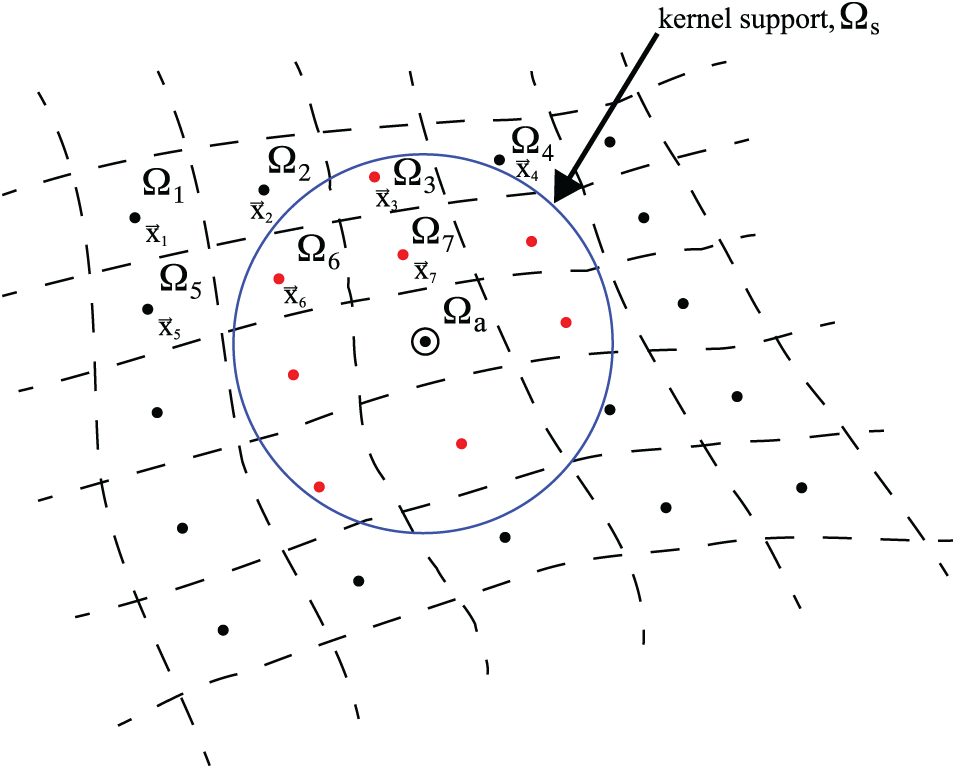
Figure 1: Schematic drawing showing the SPH discretization and the kernel support. Figure taken from Sigalotti et al. [66]
The evaporation of a liquid drop embedded into a hotter medium occurs because heat is transferred from the medium to the drop surface by conduction and/or convection, where it is converted into latent heat (or enthalpy) of vaporization. The amount of vapor that forms above a liquid is proportional to the temperature and therefore it is usually measured as the vapor pressure of the system. At higher heating temperatures, a greater number of surface molecules will acquire enough thermal energy to overcome the intermolecular attraction forces of the liquid and enter the vapor phase, resulting in increasing vapor pressure. A measure of the intermolecular attraction forces between pairs of liquid molecules is the latent heat
where A is an experimental constant related to the normal point of boiling. Taking the logarithm on both sides of Eq. (18), yields the expression
which is the equation of a straight line of slope
2.5 Classical Equations of Hydrodynamics
In the presence of thermal effects the motion of the fluid is described by the physical principles of mass, momentum, energy, and entropy balance. Under a Lagrangian framework, these conservation laws correspond to the set of coupled partial differential equations
where
with
with
is the entropy production.
SPH simulations of drop evaporation based on Eqs. (20)–(22) were carried out by Nugent et al. [12] and more recently by Harisankar et al. [24] and Yang et al. [26]. On the other hand, Hochstetter et al. [52] performed SPH-based calculations of the evaporation and condensation of liquids using a simplified version of Eqs. (20)–(22) for an incompressible, inviscid fluid under buoyancy effects. In their model, the energy equation was replaced by a heat conduction equation for a homogeneous medium
where
In the last five years, most work on drop evaporation has focused on SPH simulations of multiphase flows using the model proposed by Yang et al. [27,28] and variants of it. This model solves Eqs. (20) and (27) coupled to the Navier-Stokes equation for the fluid velocity
where
where
where
so that
where
where
In all classical models of two-phase fluid systems the interface dividing both fluids is assumed to be a surface of discontinuity endowed with surface tension. At the molecular scale, such an interface can be defined as a transition zone of typical width a few tens of Angströms. In contrast, the interfacial zone in a diffuse-interface model is defined by a continuous variation of an order parameter, such as the density, according to the molecular theory of capillarity [13]. In this case, the interface has an inner structure and a finite width through which the densities of both fluids are connected smoothly. Across the volume of the diffuse interface, all physical quantities are defined in terms of density variation. The diffuse-interface model has been successfully used to study diffusion mechanisms during processes of solidification and phase transitions [54–56]. In particular, Antanovskii [57] performed model simulations of binary fluids with heat and mass transfer using the fluid composition as an order parameter. Similar models were also used to study spinodal decomposition as well as drop migration and coalescence processes by thermo-capillary effects [58,59]. More recent simulations based on the diffuse-interface model coupled with vdW thermodynamics were reported by many authors to study liquid-vapor phase transitions by spinodal decomposition and homogeneous nucleation [17–20] and explosive vaporization in drops [21–23] as well as by heterogeneous nucleation in infinitely extended fluids [16,60]. Diffuse interfaces arise naturally in the description of fluids near their critical point. It is well-known that at subcritical temperatures two fluid phases separated by an interface may coexist in equilibrium. However, as the critical point is approached from below the binodal curve, the diffuse interface becomes thicker and thicker, and the effects of surface tension decrease. Eventually, at the critical point, the interface becomes infinitely diffuse and the surface tension vanishes. In the context of critical phenomena, there are in the literature a few works dealing with the dynamics of diffuse interfaces. For example, Felderhof [61] derived the equations governing the dynamics of diffuse interfaces near the critical point using a Lagrangian formalism, while Langer et al. [62] studied the condensation of a vapor near its critical point using a coarse-grained approximation.
2.6.1 Mean-Field Approximation
In the mean-field approximation, the thermodynamics of the liquid-vapor transition phase and the diffuse interface are described by the vdW capillarity model [14]. In this model the free energy per unit volume of the fluid is given by
where F is the volumetric free energy of the fluid,
These two conditions imply, respectively, that the temperature and generalized Gibbs free enthalpy must be uniform at equilibrium. By differentiation of Eq. (36) with respect to
where it has been made use of the identity
Since at equilibrium
and the equilibrium condition becomes
where
2.6.2 Modified Hydrodynamic Equations
The dependence of the fluid energy on the non-local term
where now the heat flux vector
This tensor vanishes as the system approaches the critical point as does the surface tension. The third term on the right-hand side of Eq. (47) is a non-classical energy flux associated with the capillarity coefficient
3 Fundamentals of the SPH Method
The SPH method was independently introduced in the literature in 1977 by Lucy [64] and Gingold et al. [65] for the numerical simulation of astrophysical flows of arbitrary geometry and at different spatial scales in three-space dimensions (3D). Since its invention, the method has found its way into an ever-increasing number of research areas, including applications to different fields of physics, biology, engineering, health sciences, and computer graphics. SPH is grid-free and relies on a Lagrangian description of the fluid, where the fluid is represented by a finite number of discrete particles (or interpolation points). Unlike traditional mesh-dependent schemes, SPH is easy to handle under complicated physics and deformable boundaries. In this section, we shall first introduce some fundamental aspects of SPH followed by details on the discretization of the continuum equations of thermohydrodynamics.
SPH is based on interpolation theory and uses as a starting point the well-known Dirac sifting property
where
Direct differentiation of Eq. (53) with respect to coordinate
where
In a similar form the kernel estimate of the gradient of a vector function,
The particle (or SPH) approximation is obtained by dividing the computational domain,
where
Higher accuracy for the estimation of the gradient can be obtained using the alternative representation
which guarantees that the gradient vanishes exactly when
In addition, a convenient SPH replacement of Eq. (55) for the divergence of a vector function, which is frequently encountered in the literature, is given by the expression
Other variants of Eqs. (58) and (60) can be found in the literature where the factor
3.2 The SPH Heat Conduction Equation
In almost all SPH studies of evaporation and condensation processes, the heat conduction Eq. (27) is written in particle form using the formulation introduced by Cleary et al. [69], namely
where
3.3 Smoothed Particle Equations of Evaporating Multiphase Flows
A model based on Eqs. (28)–(32) was proposed by Yang et al. [27] to simulate heat and mass transfer across liquid-vapor interfaces, which was then employed in many recent SPH simulations of evaporating multiphase flows [28–30,32,71]. In SPH particle form these equations read as follows:
Note that the viscous acceleration in the Navier-Stokes Eq. (28) and the right-hand side of the continuity-like equation for vapor species (31) are set in particle form using the same SPH replacement for the conduction Eq. (61). The term
if
In this model, the effects of surface tension are calculated by adding a term of the form [72]
to the right-hand side of Eq. (28), where
Most recent SPH simulations using the above formulation have focused mainly on studying drop evaporation as a result of contact with a heated solid surface. To model the vapor generated by the liquid drop after contact with a heated wall an additional force,
where
The saturated vapor mass fraction and vapor molar mass are calculated using Eqs. (33) and (34), respectively. During evaporation, the mass of vapor particles will increase at the interface, while that of liquid particles will consequently decrease. This implies that the mass of SPH particles changes during the numerical simulation. Therefore, to prevent large differences in the mass among particles about the same phase, Yang et al. [28] have implemented the criterion that when a mass particle exceeds a large critical value, the particle splits into two small particles, while on the contrary, if the mass particle is smaller than a small critical value, the particle merges with its nearest neighboring particle. For more details on the particle splitting and merging procedures, the interested reader is referred to Refs. [28,74].
3.4 Smoothed Particle Non-Classical Equations Describing a Diffuse Interface
An alternative SPH scheme to the one developed more recently by Yang et al. [27,28], known as the van der Waals square gradient model, was introduced in the literature by Charles et al. [15] in late 2011 to study the nanoscale condensation of water. This model is based on an extension of Nugent et al.’s [12] formulation to include non-classical thermodynamics through a diffuse-interface description, where the inhomogeneous interfacial region is described as smoothly varying in density. This model has been extensively applied by many authors to study first-order phase transitions and equilibrium properties of vdW multiphase systems, resulting from ordinary evaporation [17–20] and explosive vaporization [21–23] of liquid drops, and is based on the modified balance Eqs. (45)–(48), which admit the following smoothed particle representations
where
so that
4 SPH Models of Drop Evaporation with Standard Classical Thermodynamics
The first SPH simulations of drop circularization by surface tension and evaporation at subcritical temperatures were reported by Nugent et al. [12]. In their two-dimensional models, the liquid-to-vapor phase transition in evaporating drops was calculated using a vdW equation of state. Unlike most SPH simulation models of free-surface flows at that time, surface tension was not handled as an input parameter since it arises naturally from the cohesive part of the vdW equation of state. At the vapor-liquid interface, the vdW cohesive action translates into an attractive, long-range force normal to the interface that points toward the bulk of the liquid phase, so that there is no need to explicitly track the surface since the details of the local surface curvature are reproduced automatically. The SPH governing equations employed by Nugent et al. [12] include the summation interpolant for the particle density
which conserves mass exactly and replaces the smoothed particle continuity Eq. (76) to second-order accuracy. The momentum balance equation is the same as Eq. (77) without the last term on the right-hand side, while the specific internal energy is as Eq. (78) but without the third and fifth terms on the right-hand side and with the smoothed heat conduction term given instead by the symmetrized representation
where
respectively. The right-hand side of Eq. (83) strongly resembles the form used by Morris et al. [75] to estimate the surface normals for the calculation of surface curvatures with SPH in the framework of the continuum-surface-force (CSF) method. The choice of H was determined by the same considerations that led to interfacial stability with the CSF method. Thus, the forces represented by Eq. (83) largely cancel in the bulk of the liquid, except for a small strip of width H around the drop surface, where liquid particles are constrained to move inward in the opposite direction to the outward surface normal, leading to a net surface tension due to the local surface curvature. As the interpolating function, Nugent et al. [12] used the quartic spline kernel introduced by Lucy [64]
which is appropriate in two-space dimensions. In all simulations, they used 2500 SPH particles of equal mass (
Square drops of length
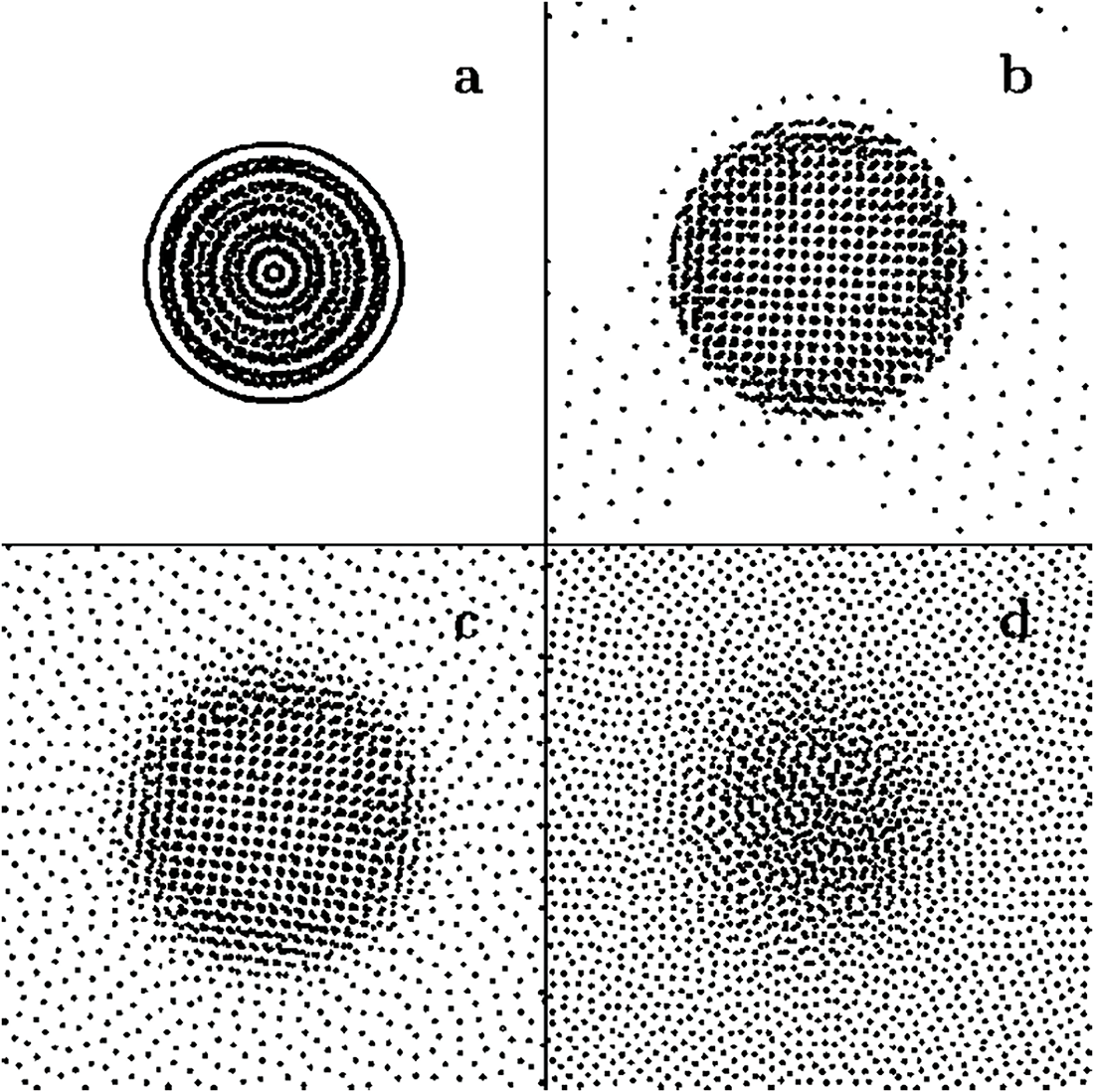
Figure 2: Stable circular drops in equilibrium with their vapor atmosphere formed from a square-shaped vdW liquid of initial subcritical temperature (a)
In a very recent work Harisankar et al. [24] used Nugent et al.’s [12] model to study the formation of bare liquid drops by surface tension and their evaporation when a small amount of energy, corresponding to 10% of the maximum particulate specific internal energy is added to the evolving drop every time step till 10,000 time steps after which the heat supply was stopped. In essence, their model differed from Nugent et al.’s [12] approach only in the choice of the kernel function. In this case, Lucy’s [64] kernel was replaced by the hyperbolic-shaped kernel function introduced by Yang et al. [76], namely
where
Harisankar et al. [24] simulated the complete vaporization of a model circular drop of initial temperature
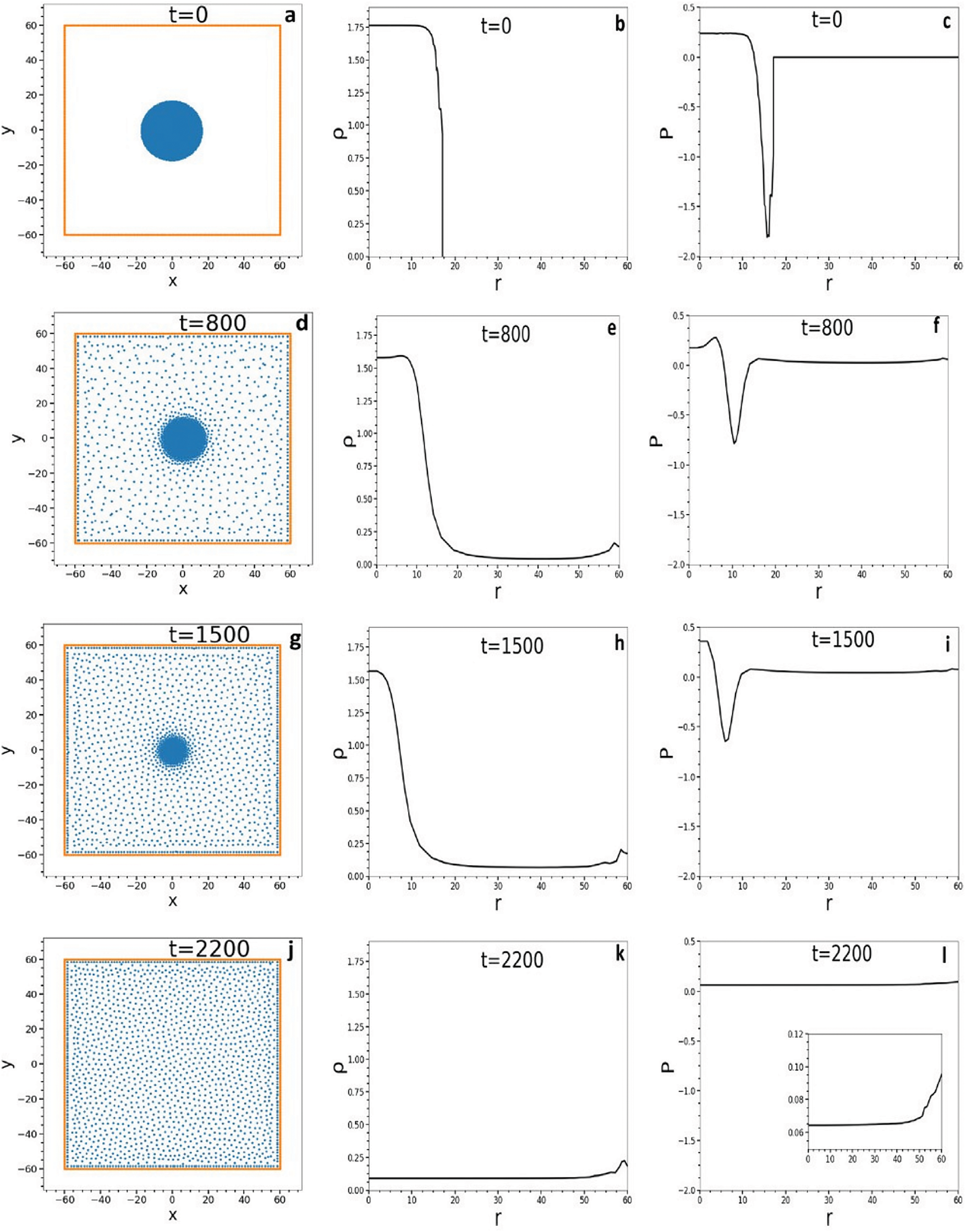
Figure 3: Sequence of snapshots showing the evolution to complete vaporization of a bare drop consisting of 1740 SPH particles with an initial temperature
The drop evaporation by impingement on heated surfaces is a related topic of research that has attracted great interest in science and engineering due to its occurrence in many industrial processes, such as, for example, spray cooling, fuel injection, fire suppression systems, inkjet printing, and fuel spray in internal combustion engines, among many other applications. Numerous recent SPH simulations relying on variants of the Nugent et al.’s [12] approach have been performed to study the spreading and evaporation of drops impacting upon heated solid surfaces. In particular, Yang et al. [26] performed three-dimensional simulations of the interaction of fuel (
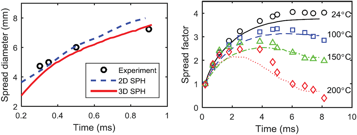
Figure 4: (Left) Time evolution of the spread diameter of a 2.4 mm diameter ethanol drop impacting on a solid wall at
The evolution of a 1.5 mm diameter
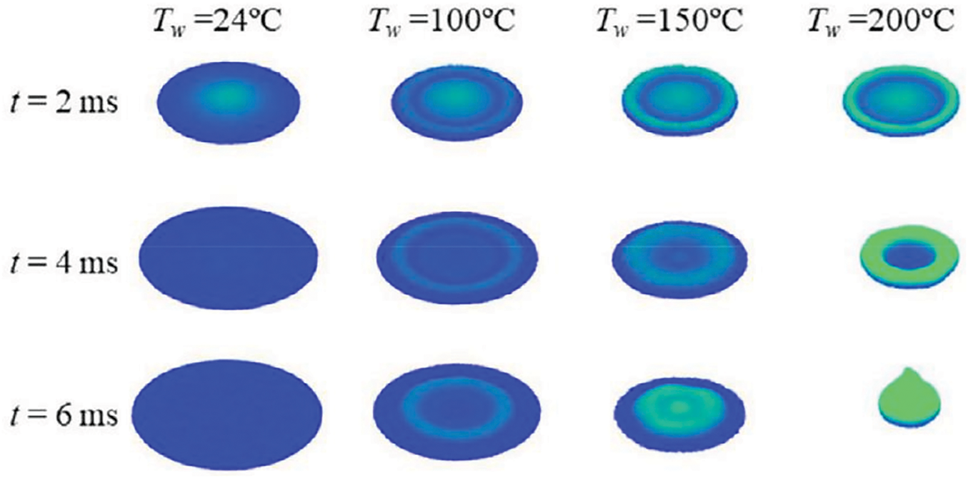
Figure 5: Deformation of a 1.5 mm diameter
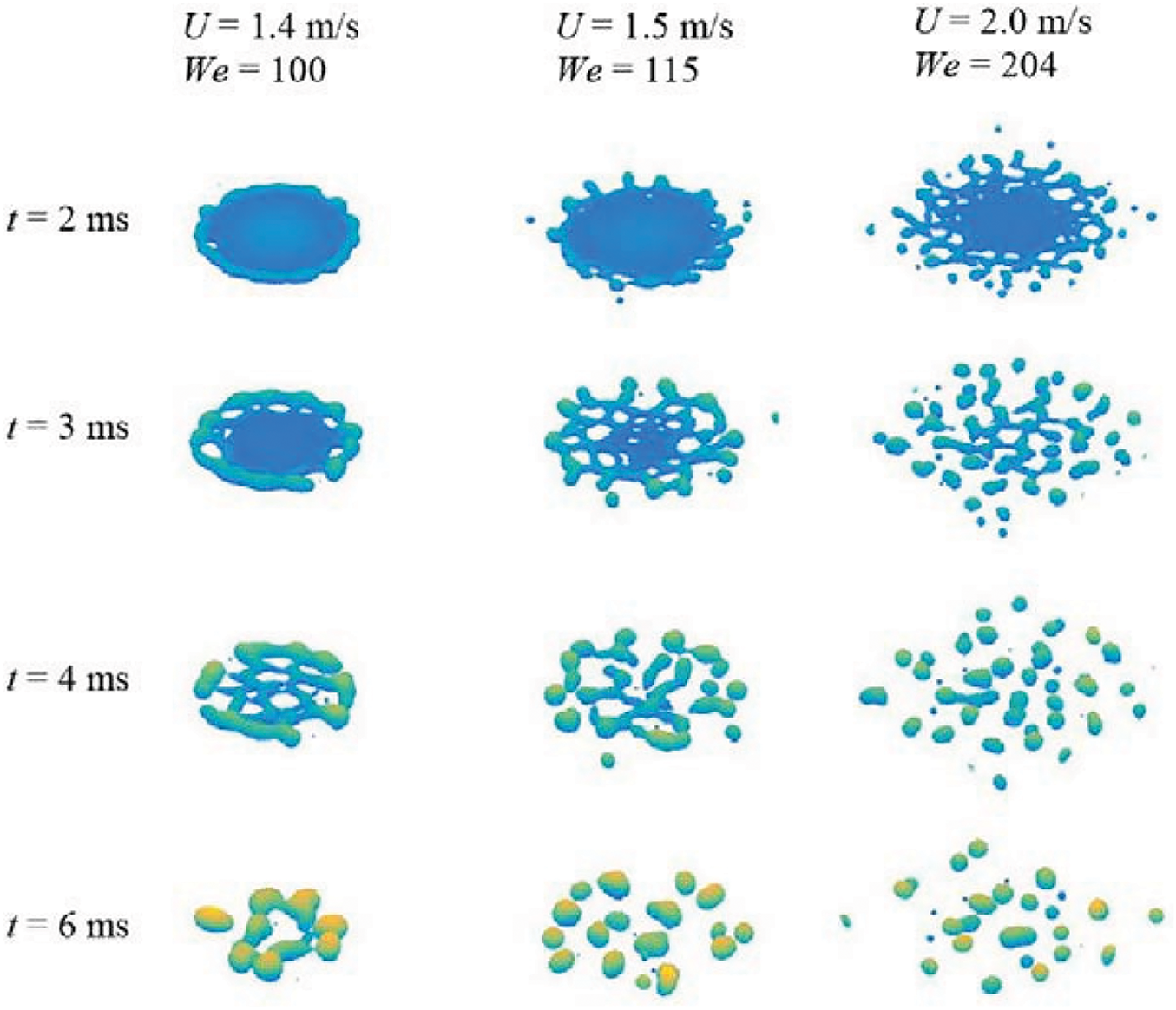
Figure 6: Drop deflagration after impact on a surface at
A modified SPH model to simulate the spreading dynamics of nanofluid droplets on heated walls was recently proposed by Liu et al. [40], where the fluid surface tension and wetting absorption during droplet wetting on a solid surface is modeled by adding a source force,
if
where
where
where
Based on the above SPH model, Liu et al. [40] simulated the wetting and de-wetting dynamics of sessile nanofluid droplets on a solid surface from non-heating to sub-boiling to super-boiling temperatures. In particular, when a nanofluid droplet impacts a sub-boiling heating plate the buoyancy force causes a slight change in the local velocity direction near the drop bottom where the temperature is characterized by a layered gradient. At a sub-boiling surface temperature of
At super-boiling temperatures of the heated plate, boiling evaporation is seen to play a dominant effect on the de-wetting stage. In this case, the experiments and the simulations also reveal two different patterns, this time depending on the heating temperature and thermal transfer. At moderate super-boiling the drop experiences intense boiling at its maximum spreading (i.e., wetting) on the surface, undergoing liquid film bursts and bubble explosion. However, during the spreading, receding, and evaporation the drop always remains in contact with the heated surface. This occurs at plate temperatures
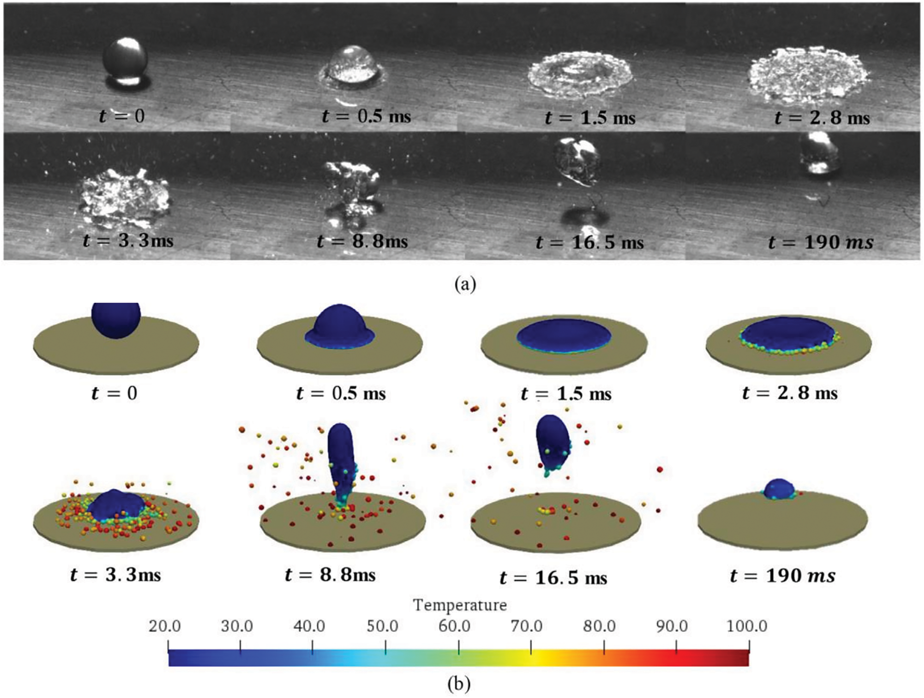
Figure 7: Impact of a nanofluids droplet on a sub-boiling heated surface at
5 SPH Models of Multispecies Flow Drop Evaporation
In general, the dynamics of drop evaporation involve phase change and energy transfer at the liquid-vapor interface along with the diffusion of vapor species in the vapor phase. As was described in Section 3.3, Yang et al. [27] proposed a reformulation of the classical model based on Eqs. (28)–(32), where a continuity equation for the vapor species was added to simulate the vapor mass fraction in the vapor phase. To account for the vapor mass increase and the liquid mass decrease during the process of liquid-vapor phase transition and avoid large mass differences at the liquid-vapor interface they introduced a particle splitting and merging technique, which was formulated in such a way as to conserve mass, momentum, and energy. Yang et al.’s [27] model and variants of it have been successfully applied to study the evaporation of static drops embedded in a heated gas. However, most studies were addressed to investigate the evaporation of liquid drops impacting on a heated surface.
Although most existing model simulations of drop impact on heated surfaces are validated for conditions at atmospheric pressure, Yang et al. [28] solved Eqs. (28)–(32) complemented by the pressure-density relation (11) to simulate the impact of a 50
At We
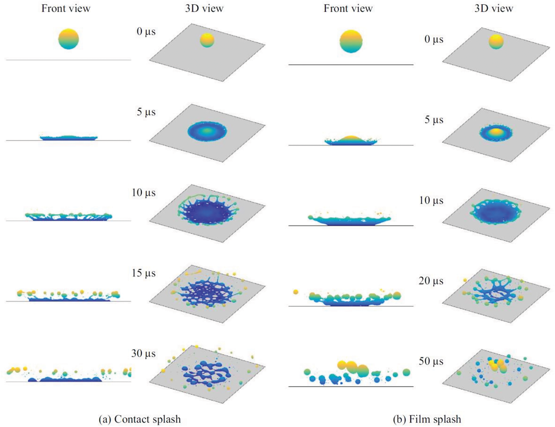
Figure 8: Impact of a 50
In a recent paper, Sohag et al. [29] reported three-dimensional SPH simulations of the impact of 50
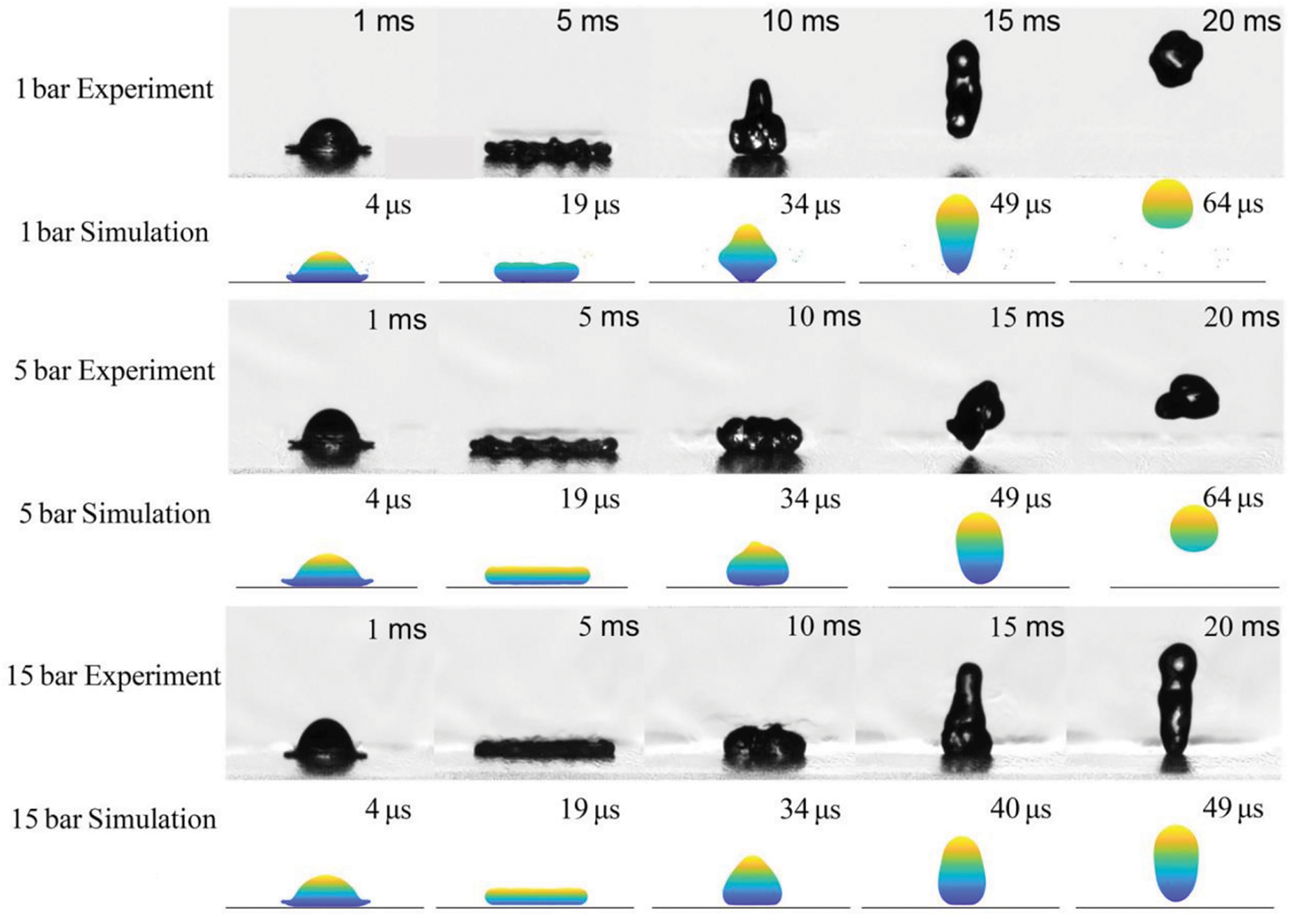
Figure 9: Impact of a 50
The simulations reported by Sohag et al. [29] focused on two different drop-impact regimes: spread and rebound. They found that the ambient pressure has little effect in changing the maximum liquid film spread. For example, Fig. 10 shows the temporal dependence of the spread factor for the
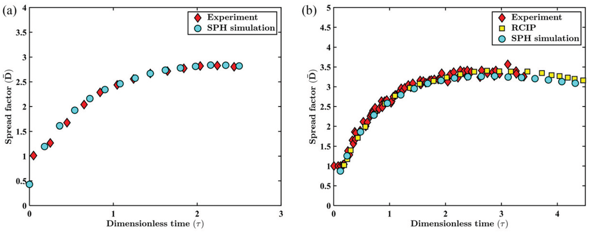
Figure 10: (a) Numerically predicted variation of the spreading factor as compared with experimental observations [86] after impact at We
An extension of Yang et al.’s [27,28] SPH formulation has been employed by Wang et al. [35] to provide a framework for direct numerical simulations (DNS) of drop evaporation and combustion processes. In particular, the movement of drops in an infinite flow field is allowed by implementing non-reflective boundary conditions in a limited area along with heat and mass transfer and chemical reaction processes. Their formulation includes a solution of the continuity Eq. (20), the momentum Eq. (28), augmented by a surface tension term of the form given by Eq. (67) using Qiang et al.’s [88] formulation for the color function and its gradient, the energy equation
where
The combustion heat of
Wang et al. [35] applied their scheme to the simulation of drop evaporation in a forced convection environment and the combustion of static single and multiple drops. In the first case, the evaporation of a 200
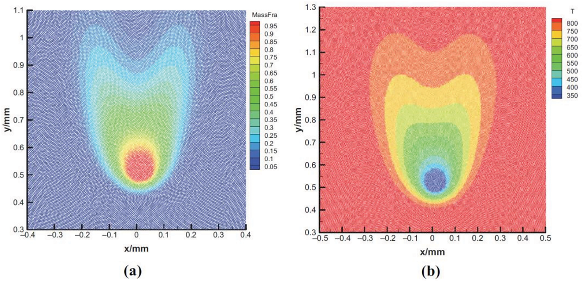
Figure 11: Numerical results for the evaporation of a 200
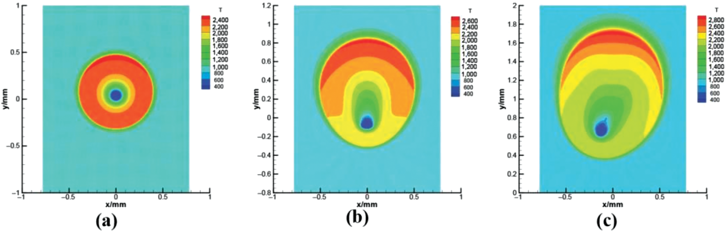
Figure 12: Predicted temperature field during the combustion of a 100
The drop evaporation after impact on the liquid film in a horizontal falling film evaporator was recently studied by Fan et al. [32] using Yang et al.’s [27,28] SPH formulation. The horizontal tube falling film evaporation is a promising technology that is widely applied in refrigeration and water treatment systems with great advantages in the heat and mass transfer efficiency and low cost [90–92]. The evaporation process of a drop impacting on a liquid film in falling-film heat exchangers not only relates to the flow and spreading dynamics after impact but also to the thermodynamic process of phase transition. Apart from related work by Xu et al. [31], Cui et al. [39], and Wang et al. [91], among other scholars, there are only a few instances in the literature dealing with SPH applications to liquid film evaporation. As a validation test case, Fan et al. [32] simulated the evaporation evolution of an ethanol droplet after impact on a heated surface, finding a fairly good agreement with ad hoc experimental observations for an ethanol drop of equivalent diameter
A schematic drawing of the evaporation model of drop impact on the liquid film employed by Fan et al. [32] is displayed in Fig. 13. The falling drop of radius 0.1 mm and temperature 313 K is placed at the center of a rectangular domain filled with gas at 333 K. The same initial temperature was used for the liquid film, while the wall temperature was set to 341 K. As the drop impacts the liquid film, a small crown first forms, which then spreads out as the drop merges gradually with the liquid film. When the initial drop velocity grows from 1 to 3 m
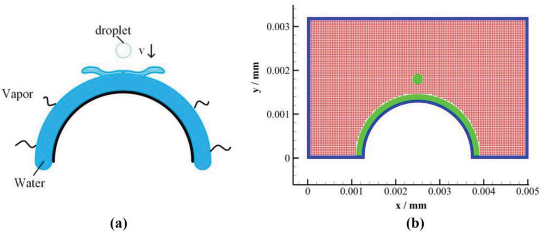
Figure 13: (a) Schematic drawing of a water drop in air impacting on a hot liquid film resting on a heated arched surface and (b) computational model domain. Figure taken from Fan et al. [32]
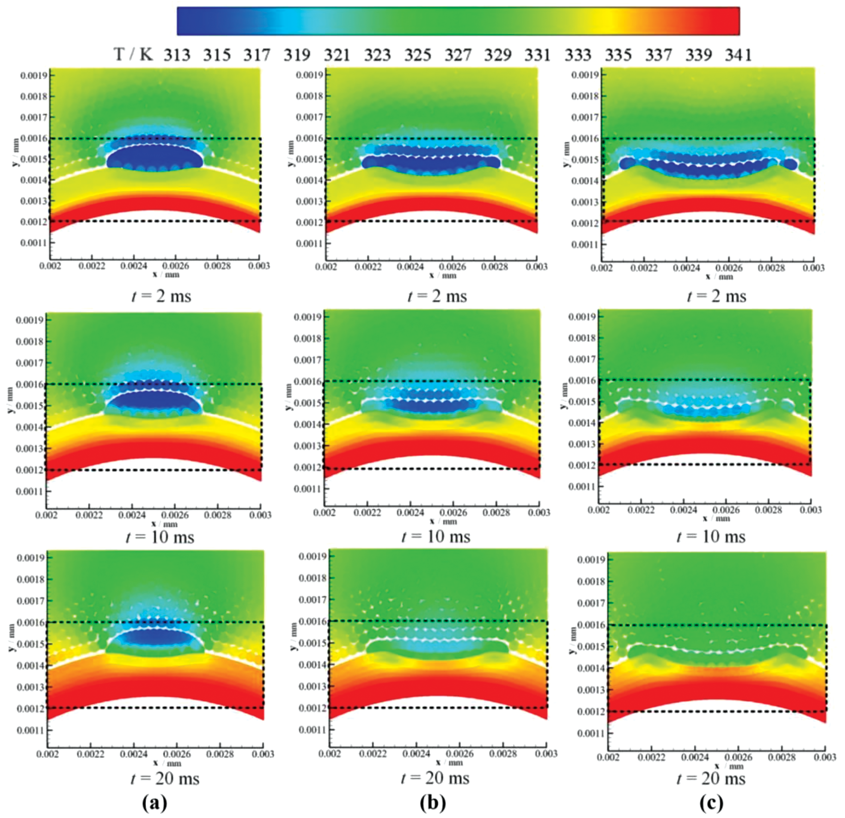
Figure 14: Temperature distribution at different times after the impact of a water drop initially at a temperature of 313 K on a hotter liquid film at a temperature of 333 K. The snapshots show the drop evaporation at different times in the top part of the arched liquid film for drop impact velocities of (a) 1 m
In a recent paper, Xu et al. [31] argued that SPH simulations of phase transitions based on ideal thermodynamics through the use of Eqs. (11) and (12) may not be accurate enough due to the decrease of liquid particles during evaporation. In order to improve the accuracy of SPH drop evaporation calculations, they proposed a formulation based on Eqs. (20), (27), and (28) coupled with Eq. (11) for the pressure-density relation, Eq. (31) for the mass fraction of the vapor species, and a time-fractional order convection-diffusion equation for the temperature of the form [93–95]
where
for
for
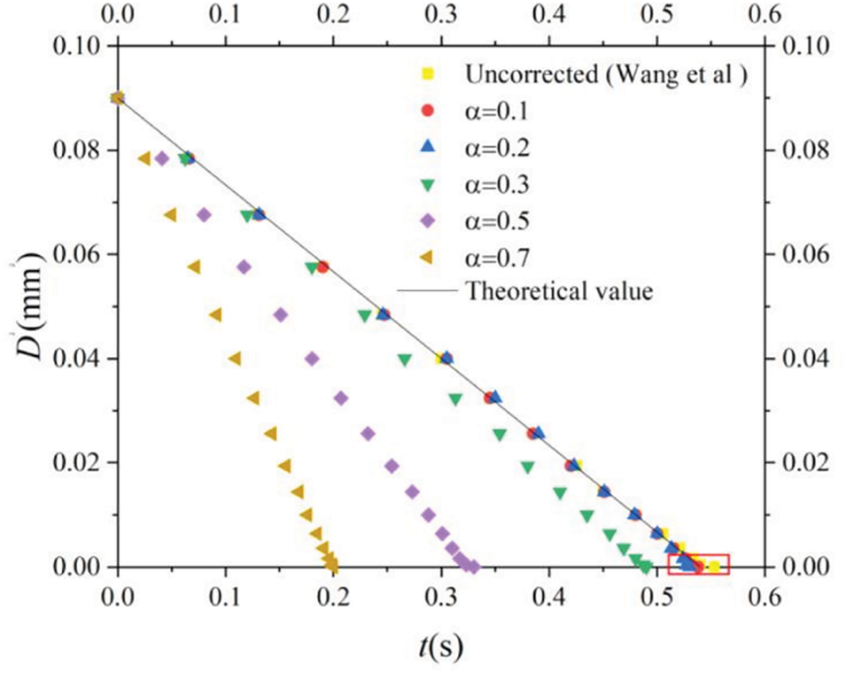
Figure 15: Temporal variation of the squared diameter of a static droplet undergoing evaporation. The colored symbols correspond to varying values of the fractional order selection (
With the above-modified scheme, Xu et al. [31] simulated the phase transition process of drops impacting on hot flat, and curved solid surfaces. Fig. 16 shows the evolution of a 0.3 mm diameter drop with an initial temperature of 573 K in a gaseous medium of the same temperature during impact on a hot arched surface. As the drop hits the surface it evaporates rapidly and a vapor film forms between the drop and the surface, which makes it float and reduces its evaporation rate. Fig. 17 shows how the spreading length and the evaporation rate of the drop vary with time. During drop evaporation, the ambient gas temperature decreases as most energy is absorbed by the evaporation process. Since the temperature of the hot surface is kept constant, the gas temperature rises again when the drop has completely evaporated.
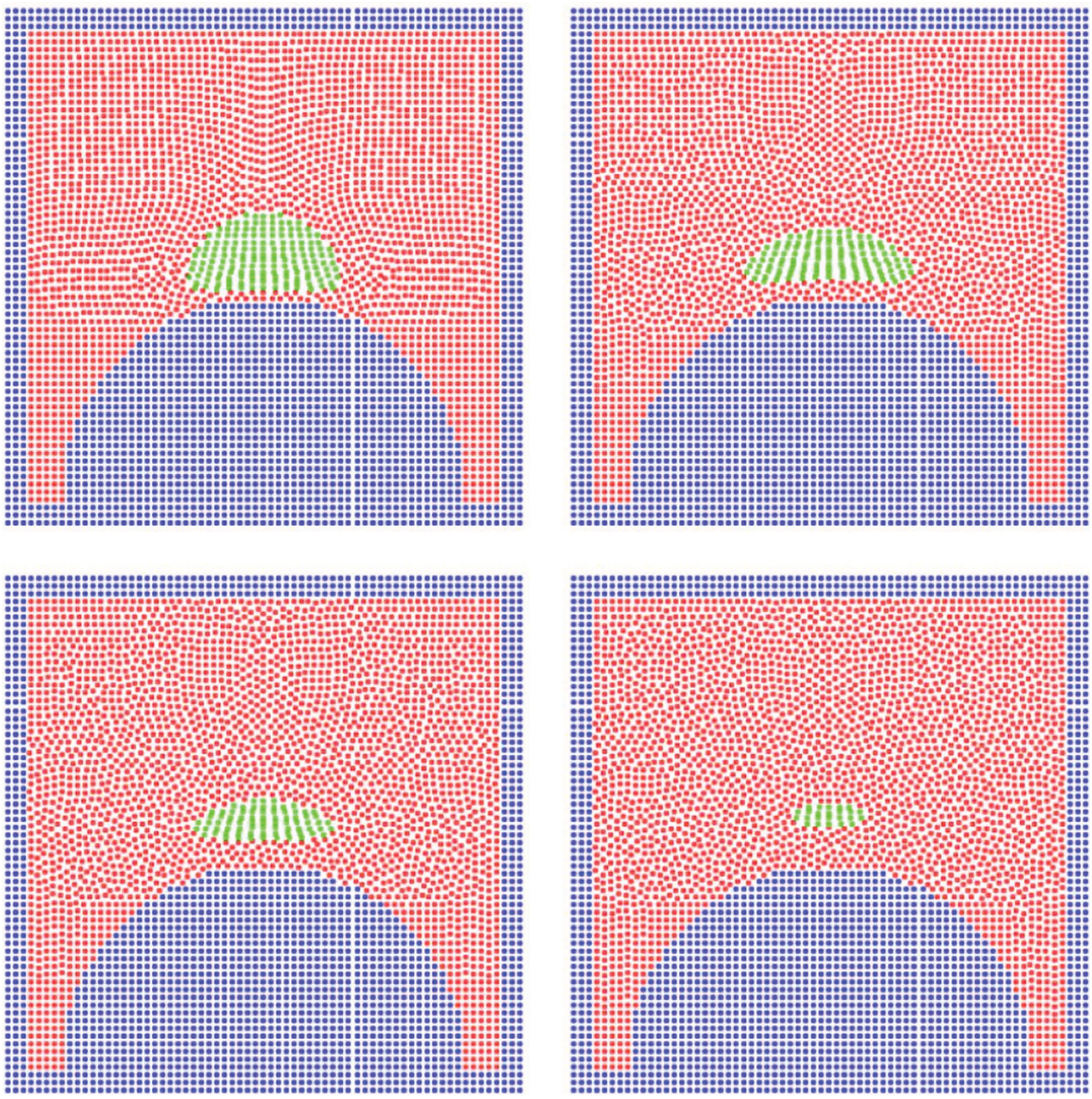
Figure 16: Snapshots showing a 0.3 mm diameter drop falling in a hot gas environment (at 573 K) and impacting on a semi-circular surface at 373 K with a velocity of 0.5 m
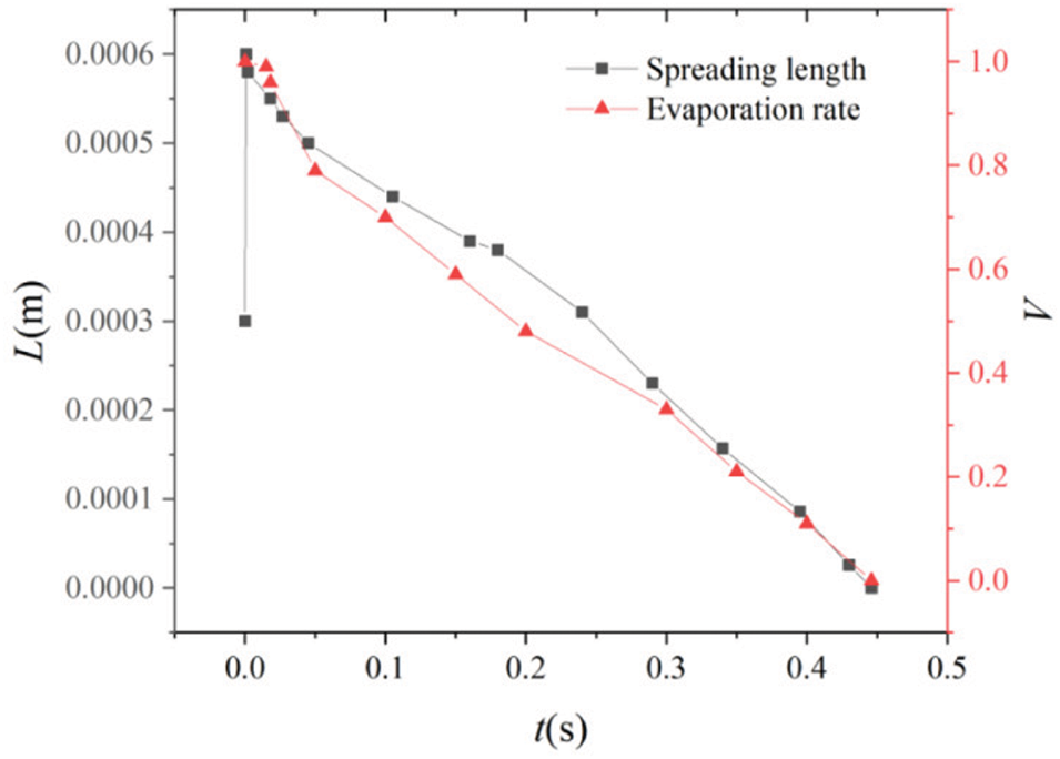
Figure 17: Variation of the spreading length and evaporation rate with time for the drop impact model of Fig. 16. Figure taken from Xu et al. [31]
In a further study, Subedi et al. [38] simulated the impact of a drop train on a hot surface at different impingement frequencies using a variant of Yang et al.’s [27,28] SPH formulation, where a Shepard filtering [96]
is applied after a certain number of timesteps to redefine the particle density so that large numerical fluctuations that may occur in the course of the simulation are effectively minimized. In addition, the XSPH technique introduced by Monaghan [43]
is used to smooth out the velocities and maintain an orderly movement of particles. Their method was first validated against experimental observations of a drop train impacting on a drywall for the radial position of the crown’s rim normalized to the drop diameter [97], finding a good level of agreement (see Subedi et al.’s [38], Fig. 2). The crown rim propagation and crater formation dynamics were also tested against the experimental measurements provided by Zhang et al. [98] for the impingement of a stream of hydrofluoroether (HFE)-7100 droplets on a pre-wetted surface for varying We numbers and impact frequencies. The numerical results were also found to be in reasonable agreement with the experimentally measured crown’s rim propagation for a falling 240
In particular, Subedi et al. [38] simulated the vertical impingement of consecutive 50
6 SPH Models of Drop Evaporation with Non-Local Thermodynamics
An alternative formulation for the numerical description of liquid-vapor phase transitions combines the pressure and caloric vdW equations with a diffuse-interface model, as was already reviewed in Section 2.6. In this formulation, the thermodynamics is based on the vdW mean-field theory and therefore the dynamics of evaporation require modification of the classical equations of hydrodynamics as given by the set of Eqs. (45)–(48), whose smoothed particle representations are given by Eqs. (76)–(79).
A simplified version of Eqs. (45)–(47), where the third term on the right-hand side of the internal energy Eq. (47) is dropped, was implemented by Sigalotti et al. [17] to investigate the evaporation of liquid drops starting from a square shape for a range of initial densities and temperatures. They found that drops with initial subcritical temperatures
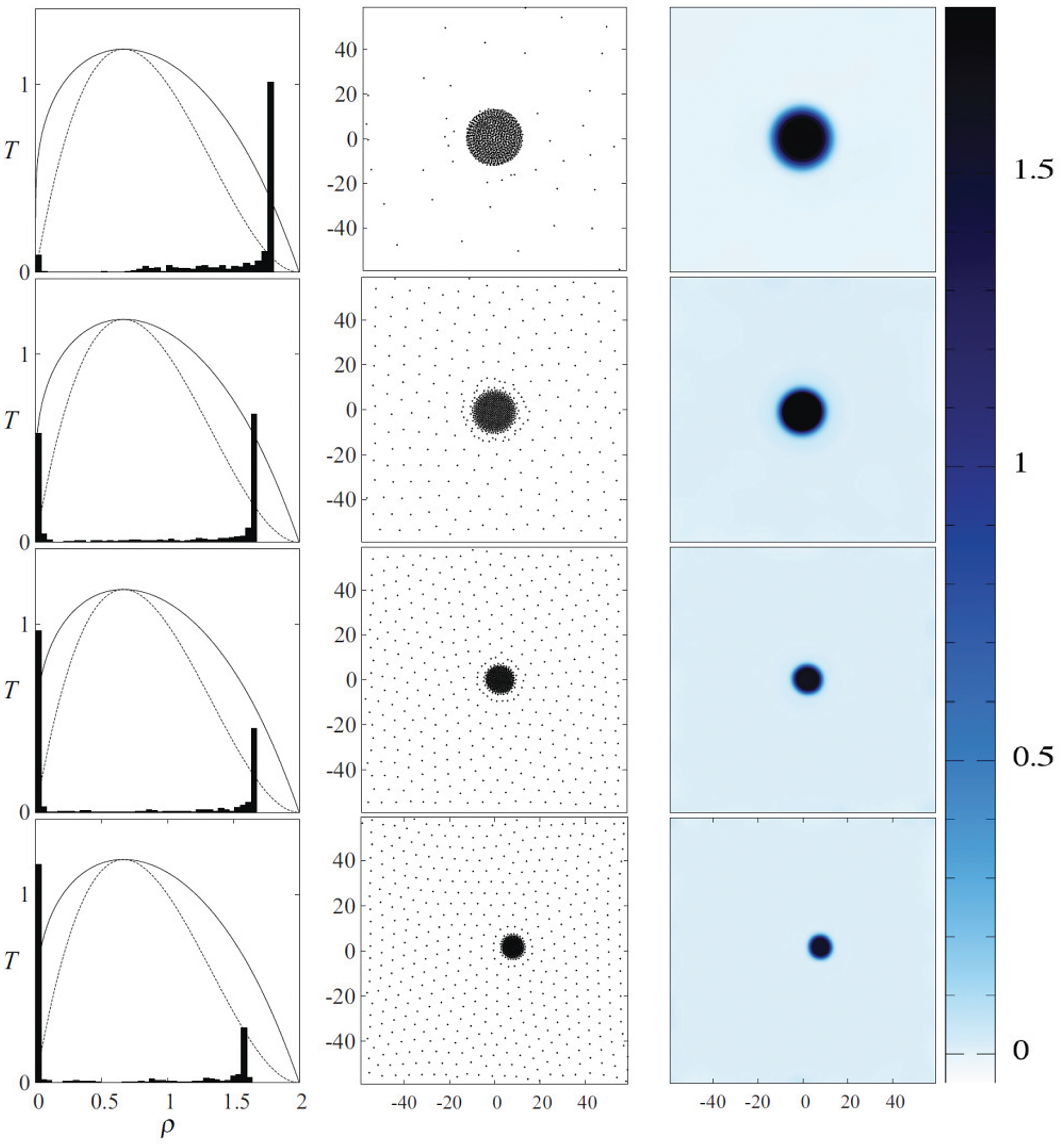
Figure 18: Stable vdW liquid drops in their vapor atmosphere after evaporation by spinodal decomposition. The equilibrium temperatures from top to bottom are 0.46, 0.64, 0.66, and 0.75 in reduced units. The normalized distribution of SPH particle densities overlayed on the phase diagram is shown in the left column of plots, while the particle positions showing the liquid and vapor phases and the spatially rendered mass density field are shown in the middle and right columns, respectively. The color-scale bar and numbers on the right indicate the density contrast in reduced units. Figure taken from Sigalotti et al. [17]
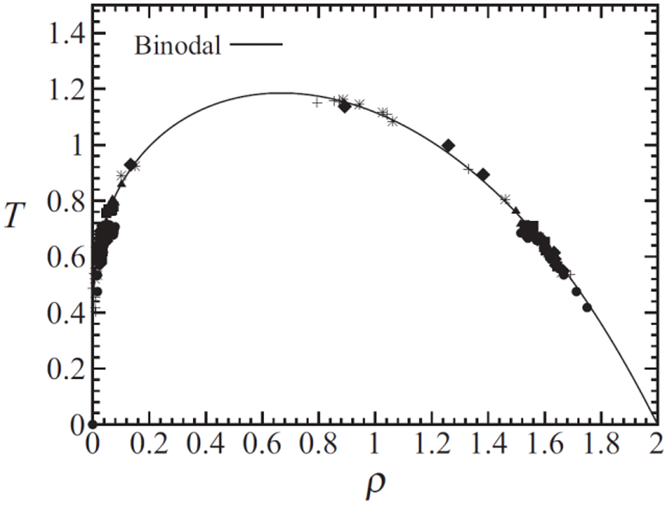
Figure 19: Equilibrium densities and temperatures for the vdW evaporation drops that produced stable liquid drops of finite size floating in their own vapor. The symbols discriminate among the model’s initial conditions (see Fig. 1 of Ref. [21]). Figure taken from Sigalotti et al. [21]
The same model formulation was further used by Sigalotti et al. [21] to simulate the evaporation and explosive vaporization of initially square-shaped drops with densities in the range between 0.31 and 1.64 in reduced units. For a fixed density, a sequence of models was produced by raising the initial drop temperature in order to predict the point separating normal boiling at subcritical heating from explosive boiling at the superheat limit. Values of
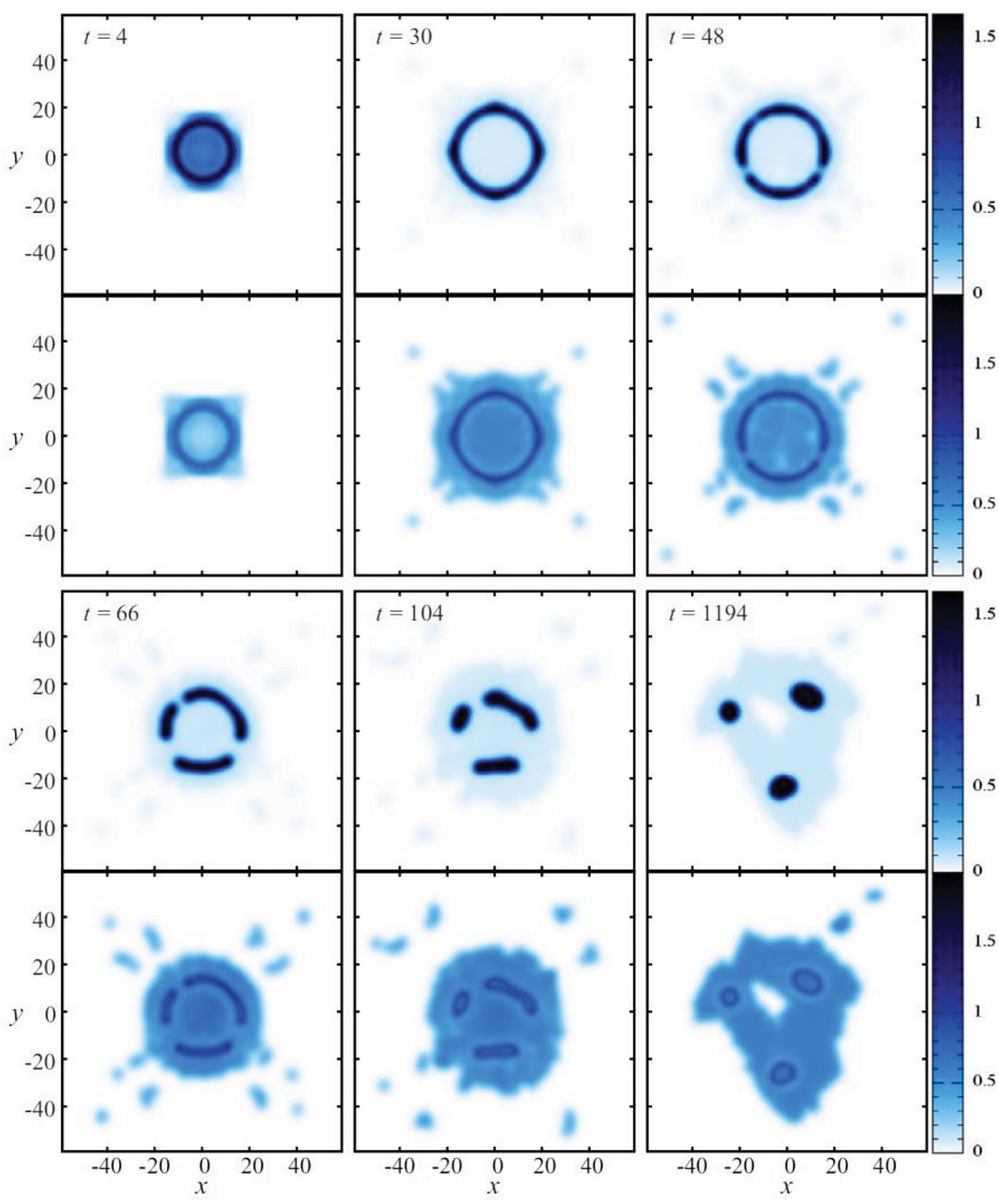
Figure 20: Snapshots of the density (upper plots) and temperatures (lower plots) showing the evaporation process of a vdW drop initially with
Water boiling on hydrophilic and hydrophobic surfaces was further simulated by Xiong et al. [18] by solving the SPH Eqs. (76)–(78), where the fifth term on the right-hand side of Eq. (78) was replaced by a volume-based external energy source (see their Eqs. (12) to (15)). In contrast with previous SPH simulations of liquid-vapor coexistence with non-local thermodynamics, they used dimensionless vdW parameters corresponding to water in terms of reference values of length (2.81 nm), temperature (562 K), time (1 ns), and mass (
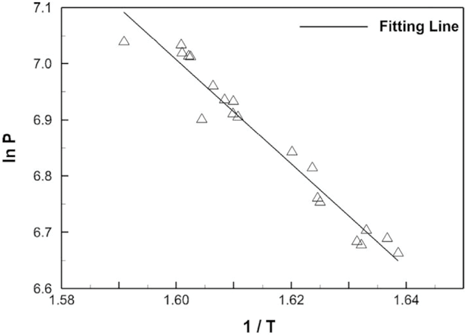
Figure 21: Linear fitting of
The same SPH model was employed by Xiong et al. [22] to simulate the vaporization of superheated drops in a vacuum and in a vapor chamber, this time using reference length, temperature, mass, and time scales of 5.326 nm, 546 K,
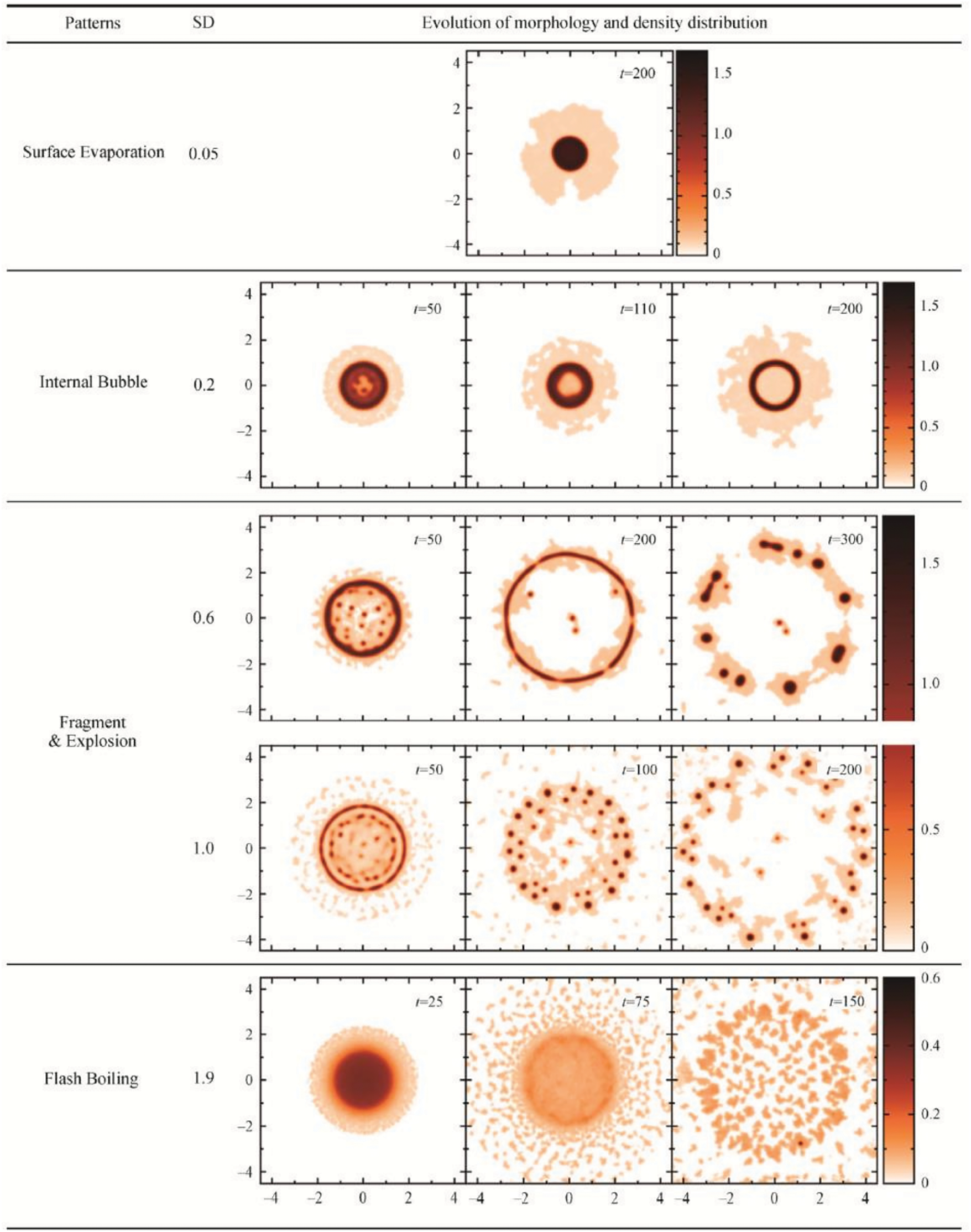
Figure 22: Rendered density field showing different evaporation patterns for a vdW drop initially with
In a more recent work, Díaz-Damacillo et al. [23] solved the SPH Eqs. (76)–(79) with the aid of the hyperbolic kernel introduced by Yang et al. [76] to study the evaporation of suspended equilibrium vdW drops. In this case, the fifth term on the right-hand side of Eq. (78) was added for the first time in order to provide a correct description of the thermal evolution and structure of the liquid-vapor interface. Starting from equilibrated circular drops with mean densities
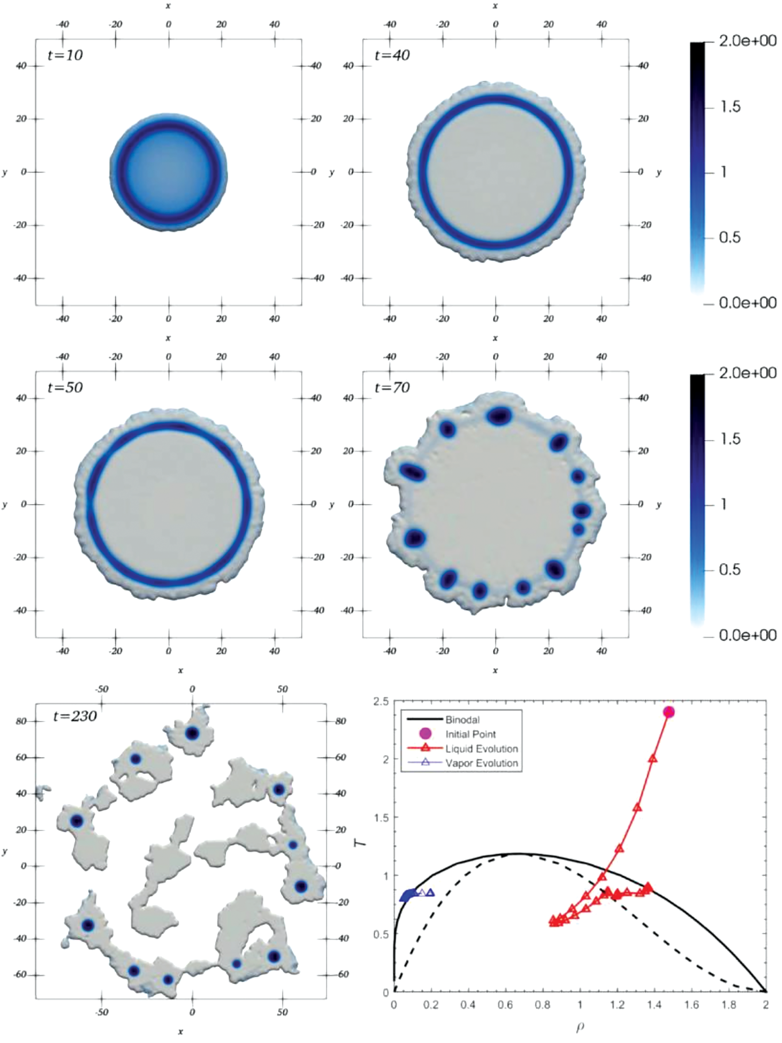
Figure 23: Rendered density field at different times during the evaporation of an equilibrium circular vdW drop initially with a mean density
In general, when liquid drops with microparticles evaporate completely on a surface, they leave a stain on it. This is typical of the so-called coffee ring effect by which the evaporated coffee drops leave a distribution pattern of particles that are more concentrated around the contact line. If the coffee drops contain nanometer particles, as they evaporate they leave instead a uniform stain of particles where they appear to be distributed evenly within the contact line. In contrast to coffee rings, this pattern deposition particle is called a coffee splat. These phenomena have been recently studied both experimentally and numerically by Xiong et al. [20], using the same vdW-based SPH formalism used previously by the same authors [18,22] coupled with a rigid particle model of finite-size microparticles, and a point-particle model for the nanoparticles. They considered the case of a drop placed on a wall of initial density
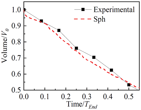
Figure 24: Temporal variation of the volume of an evaporating sessile drop of 10
Although the results shown in Fig. 24 are sufficiently convincing of the reliability of SPH to deal with problems of drop evaporation, the validity of the formulation proposed by Xiong et al. [20] was further tested against experimental observations of the flow field during evaporation of a 10
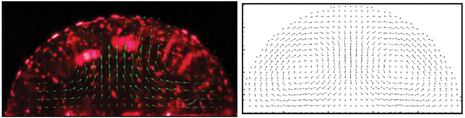
Figure 25: Experimentally observed velocity field within a sessile drop evaporating on a heated surface at
The morphology of an evaporating drop with rigid particles of diameter 0.25 (in dimensionless units; see Xiong et al.’s [20] Table 1 where the dimensionless and physical parameters are listed) is shown in Fig. 26. In this case, as the drop evaporates the rigid particles expand outwards following the steam out of the drop. However, when the diameter of the rigid particles is increased they always stay inside the drop. By comparison, the effect of point particles is depicted in Fig. 27 for the same superheat operated in Fig. 26 (i.e.,
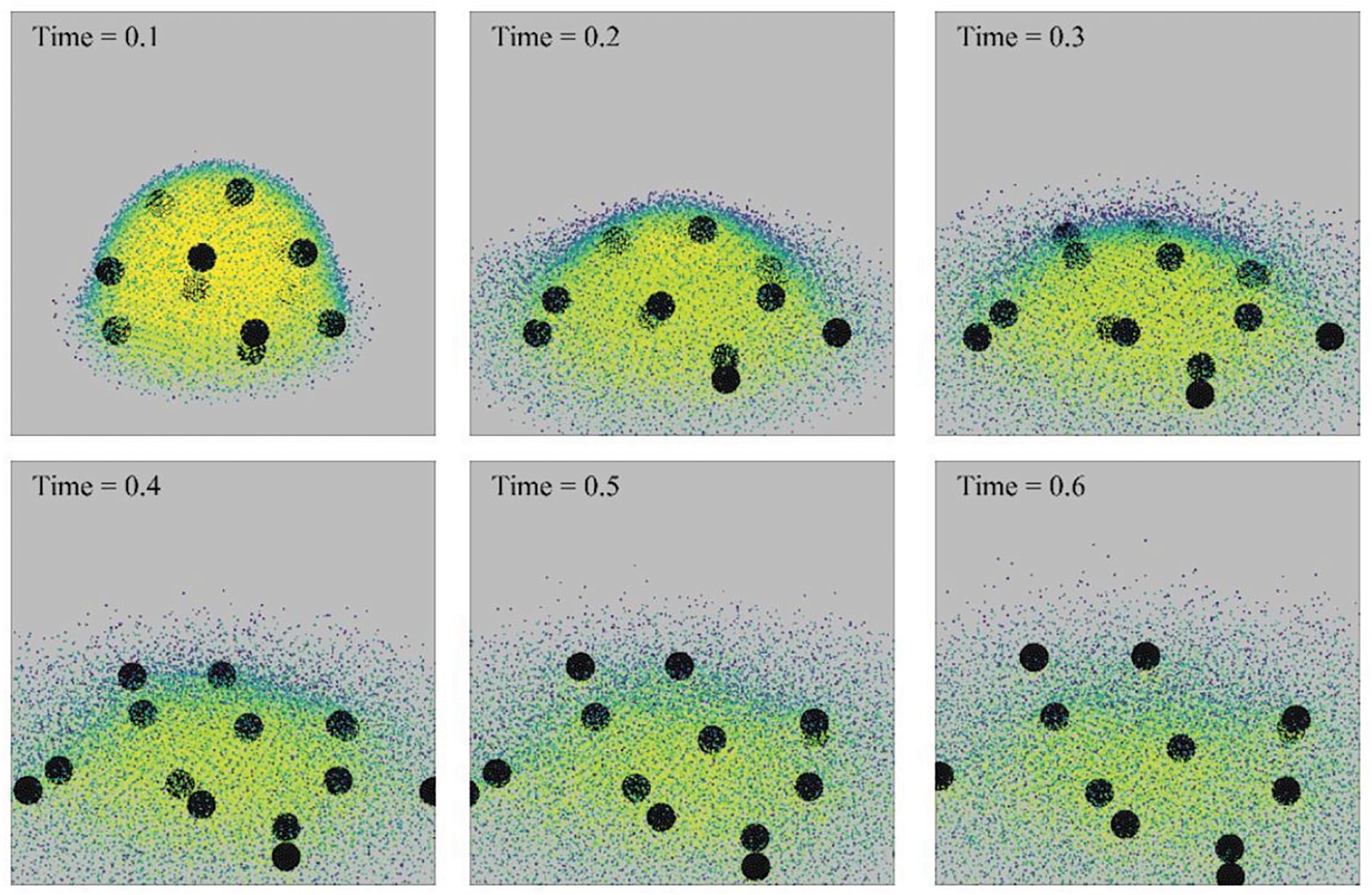
Figure 26: Snapshots showing the morphology of an evaporating sessile drop of 10
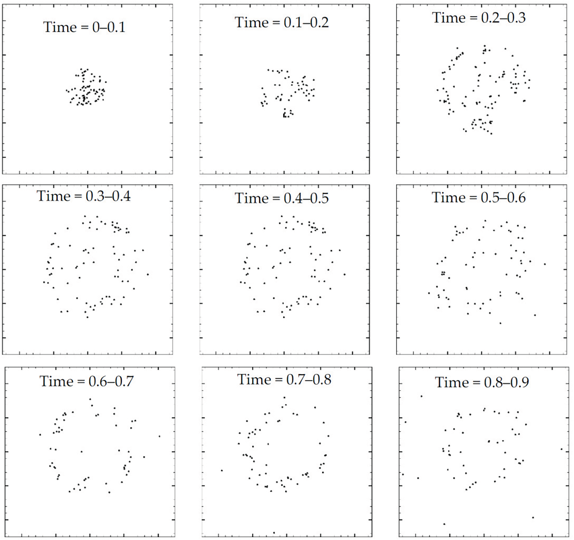
Figure 27: Snapshots showing the morphology of an evaporating sessile drop of 10
7 Limitations of the Present State-of-the-Art SPH Simulations and Future Lines of Research
Drop evaporation is a complex phenomenon involving a liquid-to-vapor phase transition. The complexity of the subject has been highlighted by Erbil [3] in his comprehensive review of the basic theory of evaporation of sessile and suspended liquid drops. The understanding of the physical processes involved during droplet evaporation under natural and industrial conditions is an important topic of research in many disciplines and has gained a wide audience over the last ten years due to the greater amount of documented experimental observations available and the emergence of increasingly sophisticated numerical methods and models. The subject has also important technological applications in an ever-increasing number of areas in science and engineering.
Among the different existing numerical methods that have been applied to study the problem of drop evaporation in its various forms, SPH has emerged as a relatively young and promising numerical method capable of modeling small to medium-sized systems from nanometric to millimetric length scales. Although significant progress has been achieved in consolidating its mathematical foundations, the method still suffers from some drawbacks, such as the lack of complete proofs of convergence and the standardization of techniques [103]. These problems leave behind a number of features that require intensive investigation. However, despite these caveats, SPH has been successfully employed in the simulation of finite-sized systems requiring the solution of the equations of fluid dynamics with heat transfer. In particular, state-of-the-art SPH simulations of droplet evaporation are based on two different formulations, which are extensions of the one implemented by Nugent et al. [12]. One formulation was introduced by Yang et al. [27] for the simulation of evaporating multiphase fluid flows, where the usual conservation laws were complemented with a continuity equation for the vapor species to simulate the vapor mass fraction in the gas phase. The second formulation, known as the vdW square gradient model, was introduced by Charles et al. [15], which uses non-classical thermodynamics based on the vdW mean-field approximation of capillarity. A number of limitations are common to both types of SPH simulations. Comments on the more relevant limitations will be provided in what follows.
7.1 Need for More Three-Dimensional Simulations
Most SPH simulations in the literature are limited to two-space dimensions, while a more realistic approach will require to model drop evaporation in three-space dimensions. Three-dimensional SPH simulations of evaporating drops have been reported in a few cases by Xiong et al. [18] for water drop boiling in contact with hydrophilic and hydrophobic surfaces and in Refs. [20,26,28,29,38,40] for fuel and nanofluids droplets impacting on a heated surface. However, there is almost a complete lack of three-dimensional SPH simulations of evaporating droplets suspended in static and convective atmospheres. On the other hand, three-dimensional simulations of non-evaporating drops have been presented by Acevedo-Malavé [51] for studying the dynamics of drop spheroidization under the effects of surface tension, and more recently, by Yang et al. [104] for studying drop impact on dry surfaces and Chaussonnet et al. [105] for studying the tree fragmentation of a mother drop in the context of biofuel production.
7.2 Need for Consistent Thermodynamics
Almost all SPH simulations of drop impact on heated surfaces using Yang et al.’s [27] SPH formulation rely on the use of ideal pressure-density relations so that surface tension effects are modeled by just adding an artificial force term to the momentum equation and a heating term to the energy equation based on a prescribed algorithm to mimic the cohesive action. In contrast, the SPH simulations of drop evaporation based on vdW thermodynamics display a liquid-to-vapor phase transition similar to that of a real fluid, while the long-range, attractive, inter-particle interaction force implicit in the cohesive term of the vdW equation of state results in surface tension. A drawback of some of these models is that the results can only be qualitatively assessed because the liquid-vapor equilibrium is predicted using vdW parameters in reduced (dimensionless) units and therefore they do not deal with realistic fluids [19,21–23]. However, Xiong et al. [18] studied drop evaporation in contact with hot surfaces using vdW thermodynamics with vdW parameters appropriate for water and Yang et al. [26] simulated the interaction of
7.3 Need for Temperature- and Density-Varying Transport Coefficients
A further important limitation that is common to all SPH simulations of evaporating drops lies in the assumption that the coefficients of viscosity and thermal conduction are constant, while in general for real liquids these coefficients are functions of density and temperature. For example, it is well-known that the shear and bulk viscosity coefficients of most liquids decrease with increasing temperature. It is common in numerical work to use the empirical relation [106,107]
to model the dependence of the shear viscosity coefficient on temperature, where A and B are empirically determined parameters [106]. Similarly, the thermal conductivity also decreases with temperature for most real liquids [107]. This can have important effects on the vapor conductivity especially in cases where the drop undergoes homogeneous nucleation followed by explosive vaporization. The dynamics of the bubble growth and the intensity of the explosion depend on the heat exchange between the vapor and the liquid layer around it [108]. In addition, for poorly conducting liquids, the rate of heat transfer from the liquid to the vapor decreases and, as a consequence, the dynamics of the bubble growth will be affected. Therefore, the assumption of constant transport coefficients limits the possibility of quantitative comparisons with experimental observations of the ordinary and explosive boiling of liquid drops. However, despite this, the landscape of SPH simulations of evaporating drops remains largely focused on constant viscosity and heat conductivity conditions. For instance, recent work on the characterization of fuel drop impact on wall films using Yang et al.’s [27] SPH formulation with constant transport coefficients was reported by Pan et al. [109,110]. A weakly compressible SPH formulation for thermo-capillary phase change problems involving solid, liquid, and gas phases using constant transport coefficients for application to selective laser melting was implemented by Meier et al. [111], which is an emerging metal additive manufacturing technique. More recently, Patwary et al. [112] reported three-dimensional SPH simulations of fuel droplets interacting with a heated wall at different ambient pressures and Weber numbers based on constant viscosity. In particular, they studied secondary atomization and proposed an empirical correlation relating the mean secondary droplet size to the ambient pressure in the film-boiling regime. Moreover, Subedi et al. [113] simulated the Leidenfrost behavior of a droplet stream impinging on a hot wall using Yang et al.’s [27] SPH formalism, finding that when the ambient pressure is increased splashing is impeded and the film concentrates inwards near the impingement point. The use of constant viscosity and thermal conduction coefficients has not only been a shortcoming of most SPH simulations, but also of simulations with other numerical methods [114–117].
Recently, the effects of variable viscosity have been studied in droplet collision dynamics for complex fluid systems, where interactions between liquid/liquid and liquid/air interfaces are involved [118]. In this case, however, the temperature dependence of viscosity on droplet collisions for both Newtonian and non-Newtonian fluids has been simulated using Direct Numerical Simulations with the aid of a Volume-of-Fluid method. For the liquid the temperature-dependent viscosity was modeled using the Arrhenius-type equation
where
A new SPH scheme developed for simulations of multi-component fluid mixing with thermally-driven buoyancy and temperature-dependent viscosity was presented by Reece et al. [119,120]. In this case, the SPH scheme was applied to study vitrification processes in the nuclear industry for waste immobilization before long-term storage. A list of ten different equations for viscosity as a function of temperature is provided by Reece [120]. However, of these equations the preferred ones for modeling melt viscosities of glasses in the vitrification of nuclear waste are those given by [121]
where A, B, C, D, and K are empirical parameters. In Eq. (101),
A notable analytical model for the heating and evaporation of a single component liquid drop was developed by Cossali et al. [122], which includes a temperature-dependent density, diffusivity, thermal conductivity, and specific heat of the gas species. They performed a comparison of the effects of variable properties on heat and evaporation rates with predictions of a constant property model for six different species, including water, acetone, ethanol,
which is consistent with monoatomic gases at low density [123], where
Rheologically complex fluids and materials are of great importance in numerous processing operations in the industry. In general, good examples of these materials are polymer solutions and biological fluids. Other examples are given by coated sheets, optical fibers, and plastics, which are important in many manufacturing processes. Therefore, more efficient production methods and manufacturing procedures can be designed by improving our understanding of their physical behavior. In response to this, a great amount of research dealing with the characterization, modeling, and simulation of non-Newtonian fluid flows using grid-based traditional numerical methods has been performed during the last three decades. In comparison only a few SPH simulations have been reported to date.
The first simulations of non-Newtonian fluid flows using SPH were reported in 2002 by Ellero et al. [129], where a corotational Jaumann-Maxwell model was employed to describe the viscoelastic behavior of the fluid. Shortly after, Shao et al. [130] studied the dynamics of viscoelastic fluid flows with free surfaces using a modified form of the Cross model. The ability of SPH to simulate transient viscoelastic fluid flows was assessed by Ellero et al. [131]. They simulated the start-up flow between parallel plates for a viscoelastic (Oldroyd-B) and an upper-convected Maxwell (UCM) fluid at a low Reynolds number, finding very good agreement with available analytical solutions. Later on, in 2007, Hosseini et al. [132] simulated non-Newtonian fluid flows using standard SPH techniques, including power-law, Herschel-Bulkley, and Bingham-plastic models. They considered three different test cases, namely a non-Newtonian dam-break problem, flow through a viscometer for different non-Newtonian fluids, and a laminar mudflow on a mild slope. The impact of Oldroyd-B and UCM fluid drops on a rigid plate was further investigated by Fang et al. [133]. Their results for the Newtonian and Oldroyd-B fluids were found to reproduce quantitatively well those obtained by Tomé et al. [134] using finite-difference methods. Xu et al. [135] reported three-dimensional SPH simulations of non-evaporating, Newtonian, and non-Newtonian drops impacting on a solid wall, in which the viscosity was modeled using the Cross model. Their results indicate that the Newtonian droplet spreads out by keeping a convex shape during the impact, while the non-Newtonian drop behaved differently due to the shear-thinning effect, achieving a larger spreading radius than its Newtonian counterpart. Their SPH scheme was also applied to two-dimensional simulations of transient viscoelastic fluid flows, where the polymer dynamics was described by the evolution of continuous Brownian configuration fields [136]. More recently, Tembely et al. [137] performed simulations of drop impact on different substrates for Newtonian and polymer solutions using a Volume-of-Fluid method. Moreover, Shi et al. [138] extended the
7.5 The Issue of Spatial Resolution
A further important factor is the issue of spatial resolution. For example, as resolution is increased quantitative differences can appear in the morphology of the system and the number of secondary droplets produced in overheated drops undergoing rapid or even explosive fragmentation. In addition, resolution can also influence the breakup times of the liquid layer due to bubble growth and the structure of the diffuse liquid-vapor interface. There are almost no publications showing convergence studies in SPH droplet simulation. However, Xu et al. [135] demonstrated that increasing the resolution from 55,552 to 749,078 particles in Newtonian and non-Newtonian drop impact simulations has little effect on the results when measured in terms of the evolution of the drop width. This situation will certainly change in drop simulations of fragmentation and explosive vaporization where a plethora of tiny droplets accompanied by vapor are produced. Therefore, in order to clarify how spatial resolution affects the drop evaporation process, it is necessary to carry out three-dimensional convergence studies in these cases and assess the validity of the numerical predictions by direct comparison with experimental data.
Since there is great interest in engineering applications where the liquid-vapor equilibrium is crucial to the development of predictive models of evaporating fuel droplets in engines for spray combustion, future simulations must include chemical reactions in order to simulate the evaporative combustion in multi-component fuel drops. On the other hand, considering the influence of the various conditions that may intervene during the drop/wall interaction process, more experimental results are needed to refine the model simulations. The level of prediction of SPH drop evaporation models will depend on several factors, including improved physics, chemistry, and spatial resolution. Of course, the computational tool can be extended to include realistic thermodynamic properties to simulate other fuels and predict the outcome of drop/wall interaction at practical operating conditions. In addition to the evaporation of drop impact on heated surfaces, more simulations are needed to study the evaporation and combustion of fuel drops in convective environments. These models are of particular importance because most liquid fuels are atomized before entering the combustion chamber and undergo combustion in the form of droplet groups. The reliability of the predictions must necessarily be tested by comparing the SPH results with molecular dynamics simulations and experimental measurements.
In this paper, we provide an overview of the published work on SPH-based simulations of liquid drop evaporation. The review covers articles published since 2000 when the first SPH simulations of evaporating drops were conducted. To assist non-expert readers, the paper includes an introductory section on the theoretical background necessary for the numerical modeling of drop evaporation. A separate section introduces some fundamental aspects of the SPH method, along with the governing equations and current state-of-the-art formulations employed in these simulations. Subsequent sections provide a brief description of relevant results obtained using different formulations for drop evaporation in static and convective hot environments, as well as during impact on a heated surface or liquid film. The evaporation of sessile drops due to contact with a hot wall is also reviewed as a specific case of drop impingement on a solid surface. The overview concludes with a section discussing the limitations of current SPH model simulations and suggesting potential directions for future research. Upon reviewing the various published studies, it is evident that the SPH method has become a powerful tool for simulating both ordinary and explosive boiling of small liquid drops in a hot atmosphere, as well as drop evaporation upon contact with a hot surface. These simulations have demonstrated a high level of predictive accuracy, particularly in cases where direct comparisons with experimental data were available.
Acknowledgement: We acknowledge the Departamento de Ciencias Básicas of the Universidad Autónoma Metropolitana, Azcapotzalco Campus for continued support during the preparation of the manuscript.
Funding Statement: The authors received no specific funding for this study.
Author Contributions: The authors confirm their contribution to the paper as follows: study conception and design: Leonardo Di G. Sigalotti, Carlos A. Vargas; draft manuscript preparation: Leonardo Di G. Sigalotti, Carlos A. Vargas. All authors reviewed the results and approved the final version of the manuscript.
Availability of Data and Materials: All data generated or analyzed during this study are included in this published article.
Ethics Approval: Not applicable.
Conflicts of Interest: The authors declare no conflicts of interest to report regarding the present study.
References
1. Papon P, Leblond L, Meijer PHE. The physics of phase transitions: concepts and applications. Berlin: Springer Verlag; 2002. [Google Scholar]
2. Silberberg MS, Amateis PG. Chemistry: the molecular nature of matter and change. 9th ed. Dubuque: McGraw-Hill Education; 2021. [Google Scholar]
3. Erbil HY. Evaporation of pure liquid sessile and spherical suspended drops: a review. Adv Colloid Interface Sci. 2012;170(1–2):67–86. doi:10.1016/j.cis.2011.12.006. [Google Scholar] [PubMed] [CrossRef]
4. Thern M, Lindquist T, Torisson T. Experimental and theoretical investigation of an evaporative fuel system for heat engines. Energy Convers Manag. 2007;48(4):1360–6. doi:10.1016/j.enconman.2006.06.009. [Google Scholar] [CrossRef]
5. Birouk M, Gökalp I. Current status of droplet evaporation in turbulent flows. Prog Energy Combust Sci. 2006;32(4):408–23. doi:10.1016/j.pecs.2006.05.001. [Google Scholar] [CrossRef]
6. Chen S, Wang Z, Shan X, Doolen GD. Lattice Boltzmann computational fluid dynamics in three dimensions. J Statist Phy. 1992;68(3–4):379–400. doi:10.1007/BF01341754. [Google Scholar] [CrossRef]
7. Renardy Y, Popinet S, Duchemin L, Renardy M, Zaleski S, Josserand C, et al. Pyramidal and toroidal water drops after impact on a solid surface. J Fluid Mech. 2003;484:69–83. doi:10.1017/S0022112003004142. [Google Scholar] [CrossRef]
8. Caviezel D, Narayanan C, Lakehal D. Adherence and bouncing of liquid droplets impacting on dry surfaces. Microflu Nanoflu. 2008;5(4):469–78. doi:10.1007/s10404-007-0248-2. [Google Scholar] [CrossRef]
9. Visser CW, Frommhold PE, Wildeman S, Mettin R, Lohse D, Sun C. Dynamics of high-speed micro-drop impact: numerical simulations and experiments at frame-to-frame times below 100 ns. Soft Matter. 2015;11(9):1708–22. doi:10.1039/C4SM02474E. [Google Scholar] [PubMed] [CrossRef]
10. Monaghan JJ. Smoothed particle hydrodynamics. Rep Progress Phy. 2005;68(8):1703–59. doi:10.1088/0034-4885/68/8/R01. [Google Scholar] [CrossRef]
11. Liu MB, Liu GR. Smoothed particle hydrodynamics (SPHan overview and recent developments. Arch Computat Meth Eng. 2010;17(1):25–76. doi:10.1007/s11831-010-9040-7. [Google Scholar] [CrossRef]
12. Nugent S, Posch HA. Liquid drops and surface tension with smoothed particle applied mechanics. Phy Rev E. 2000;62(4):4968–75. doi:10.1103/PhysRevE.62.4968. [Google Scholar] [PubMed] [CrossRef]
13. Rowlinson JS, Widom B. Molecular theory of capillarity. New York: Dover; 2002. [Google Scholar]
14. Anderson DM, McFadden GB, Wheeler AA. Diffuse-interface methods in fluid mechanics. Ann Rev Fluid Mech. 1998;30(1):139–65. doi:10.1146/annurev.fluid.30.1.139. [Google Scholar] [CrossRef]
15. Charles AN, Daivis P. A three dimensional smooth particle hydrodynamics model of the nanoscale condensation of water. In: The 19th International Congress of Modelling and Simulation–Sustaining Our Future: Understanding and Living with Uncertainty (MODSIM2011). Modelling and Simulation Society of Australia and New Zealand; 2011; Perth, Australia. p. 516–22. [Google Scholar]
16. Pütz M, Nielaba P. Effects of temperature on spinodal decomposition and domain growth of liquid-vapor systems with smoothed particle hydrodynamics. Phy Rev E. 2015;91(3):032303. doi:10.1103/PhysRevE.91.032303. [Google Scholar] [PubMed] [CrossRef]
17. Sigalotti LDG, Troconis J, Sira E, Peña-Polo F, Klapp J. Diffuse-interface modeling of liquid-vapor coexistence in equilibrium drops using smoothed particle hydrodynamics. Phys Rev E. 2014;90(1):013021. doi:10.1103/PhysRevE.90.013021. [Google Scholar] [PubMed] [CrossRef]
18. Xiong H, Zhang C, Yu Z. Multiphase SPH modeling of water boiling on hydrophilic and hydrophobic surfaces. Int J Heat Mass Trans. 2019;130(1):680–92. doi:10.1016/j.ijheatmasstransfer.2018.10.119. [Google Scholar] [CrossRef]
19. Troconis J, Sánchez-Silva F, Carvajal-Mariscal I, Peña-Polo F, Sigalotti LDG, Klapp J. Simulation of van der Waals liquid droplets within a hot air atmosphere using the smoothed particle hydrodynamics method. Int J Heat Mass Trans. 2023;202(4):123749. doi:10.1016/j.ijheatmasstransfer.2022.123749. [Google Scholar] [CrossRef]
20. Xiong H, Wang Q, Yuan L, Liang J, Lin J. Modeling and experiments of droplet evaporation with micro or nano particles in coffee ring or coffee plat. Nanomaterials. 2023;13(10):1609. doi:10.3390/nano13101609. [Google Scholar] [PubMed] [CrossRef]
21. Sigalotti LDG, Troconis J, Sira E, Peña-Polo F, Klapp J. Smoothed particle hydrodynamics simulations of evaporation and explosive boiling of liquid drops in microgravity. Phys Rev E. 2015;92(1):013021. doi:10.1103/PhysRevE.92.013021. [Google Scholar] [PubMed] [CrossRef]
22. Xiong H, Wang Q, Zhang C, Wang H, Lin J. Droplet evaporation to boiling in van der Waals fluid. J Therm Sci. 2022;31(3):790–801. doi:10.1007/s11630-022-1620-y. [Google Scholar] [CrossRef]
23. Díaz-Damacillo L, Sigalotti LDG, Alvarado-Rodríguez CE, Klapp J. Smoothed particle hydrodynamics simulations of the evaporation of suspended liquid droplets. Phy Fluids. 2023;35(12):122111. doi:10.1063/5.0176846. [Google Scholar] [CrossRef]
24. Harisankar PC, Sil T. Drop-vapour coexistence in smoothed particle hydrodynamics. Eng Anal Bound Elem. 2023;151(4):56–67. doi:10.1016/j.enganabound.2023.02.039. [Google Scholar] [CrossRef]
25. Ray M, Yang X, Kong S-C, Bravo L, Kweon C-BM. High-fidelity simulation of drop collision and vapor-liquid equilibrium of van der Waals fluids. Proc Combust Instit. 2017;36(2):2385–92. doi:10.1016/j.proci.2016.06.018. [Google Scholar] [CrossRef]
26. Yang X, Ray M, Kong S-C, Kweon C-BM. SPH simulation of fuel drop impact on heated surfaces. Proc Combust Instit. 2019;37(3):3279–86. doi:10.1016/j.proci.2018.07.078. [Google Scholar] [CrossRef]
27. Yang X, Kong S-C. Smoothed particle hydrodynamics method for evaporating multiphase flows. Phys Review E. 2017;96(3):033309. doi:10.1103/PhysRevE.96.033309. [Google Scholar] [PubMed] [CrossRef]
28. Yang X, Kong S-C. Smoothed particle hydrodynamics modeling of fuel drop impact on a heated surface at atmospheric and elevated pressures. Phys Review E. 2020;102(3):033313. doi:10.1103/PhysRevE.102.033313. [Google Scholar] [PubMed] [CrossRef]
29. Sohag MMA, Chausalkar A, Li L, Yang X. Numerical study of drop spread and rebound on heated surfaces with consideration of high pressure. Phy Fluids. 2022;34(11):113319. doi:10.1063/5.0124794. [Google Scholar] [CrossRef]
30. Xiao X, Ma X, Kari T, Xu Q, Fan M. Numerical simulation of droplet evaporation based on the smoothed particle hydrodynamics method. Therm Sci. 2023;27(5A):3745–56. doi:10.2298/TSCI230311101X. [Google Scholar] [CrossRef]
31. Xu Q, Ma X, Cheng Z, Xiao X, Ma Z. Numerical simulation of conduction problem with evaporation based on a SPH model improved by a fractional order convection-diffusion equation. Eng Anal Bound Elem. 2023;155(1/2):668–81. doi:10.1016/j.enganabound.2023.06.014. [Google Scholar] [CrossRef]
32. Fan M, Ma X, Li L, Xiao X, Cheng C. The simulation of droplet impact on liquid film evaporation in horizontal falling film evaporator based on smoothed particle hydrodynamics. Int J Num Meth Heat Fluid Flow. 2024;34(6):2257–84. doi:10.1108/HFF-01-2024-0045. [Google Scholar] [CrossRef]
33. Godsave GAE. Studies of the combustion of drops in a fuel spray-the burning of single drops of fuel. Symp (Int) Combust. 1953;4(1):818–30. doi:10.1016/S0082-0784(53)80107-4. [Google Scholar] [CrossRef]
34. Spalding DB. The combustion of liquid fuels. Symp (Int) Combust. 1953;4(1):847–64. doi:10.1016/S0082-0784(53)80110-4. [Google Scholar] [CrossRef]
35. Wang D, Qiang H, Shi C. A multiphase SPH framework for solving the evaporation and combustion process of droplets. Int J Num Meth Heat Fluid Flow. 2020;30(3):1547–75. doi:10.1108/HFF-08-2019-0666. [Google Scholar] [CrossRef]
36. Mitchell RE, Sarofim AF, Clomburg LA. Experimental and numerical investigation of confined laminar diffusion flames. Combust Flame. 1980;37:227–44. doi:10.1016/0010-2180(80)90092-9. [Google Scholar] [CrossRef]
37. Li L, Yang X, Sohag MMA, Wang X, Liu Q. SPH-ASR study of drop impact on a heated surface with considaration of inclined angle and evaporation. Eng Anal Bound Elem. 2022;141(9):235–49. doi:10.1016/j.enganabound.2022.05.016. [Google Scholar] [CrossRef]
38. Subedi KK, Kong S-C, Kweon C-BM. Numerical study of consecutive drop/wall impacts using smoothed particle hydrodynamics. Int J Multiph Flows. 2022;151(13):104060. doi:10.1016/j.ijmultiphaseflow.2022.104060. [Google Scholar] [CrossRef]
39. Cui X, Bakkar A, Habashi WG. A multiphase SPH framework for supercooled large droplets dynamics. Int J Num Meth Heat Fluid Flow. 2019;29(7):2434–49. doi:10.1108/HFF-10-2018-0547. [Google Scholar] [CrossRef]
40. Liu Z, Li S, Pan X, Fang H. Mechanism study on spreading dynamics of nanofluids droplet coupled with thermal evaporation. Int J Heat Mass Trans. 2022;183(21):122172. doi:10.1016/j.ijheatmasstransfer.2021.122172. [Google Scholar] [CrossRef]
41. Sommerfeld A. Thermodynamics and statistical mechanics. New York: Academic Press; 1955. Vol. 4. [Google Scholar]
42. Becker M, Teschner M. Weakly compressible SPH for free surfaces. In: Proceedings of the 2007 ACM SIGGRAPH/Europhysics Symposium on Computer Animation; 2007; San Diego, CA, USA: Eurographics Association. p. 32–58. [Google Scholar]
43. Monaghan JJ. Smoothed particle hydrodynamics. Annual Rev Astron Astrophy. 1992;30(1):543–74. doi:10.1146/annurev.aa.30.090192.002551. [Google Scholar] [CrossRef]
44. Fowkes FM. Attractive forces at interfaces. Indus Eng Chem. 1964;56(12):40–52. doi:10.1021/ie50660a008. [Google Scholar] [CrossRef]
45. Chen R-H, Phuoc TX, Martello D. Surface tension of evaporating nanofluid droplets. Int J Heat Mass Trans. 2011;54(11–12):2459–66. doi:10.1016/j.ijheatmasstransfer.2011.02.016. [Google Scholar] [CrossRef]
46. Vafaei S, Wen D. Bubble formation in a quiescent pool of gold nanoparticle suspension. Adv Coll Interf Sci. 2010;159(1):72–93. doi:10.1016/j.cis.2010.05.005. [Google Scholar] [PubMed] [CrossRef]
47. Domec J-C. Let’s not forget the critical role of surface tension in xylem water relations. Tree Physiol. 2011;31(4):359–60. doi:10.1093/treephys/tpr039. [Google Scholar] [PubMed] [CrossRef]
48. Das SK, Putra N, Roetzel W. Pool boiling characteristics of nano-fluids. Int J Heat Mass Trans. 2003;46(5):851–62. doi:10.1016/S0017-9310(02)00348-4. [Google Scholar] [CrossRef]
49. de Gennes P-G, Borchard-Wyart F, Quéré D. Capillarity and wetting phenomena: drops, bubbles, pearls, waves. Berlin: Springer; 2004. [Google Scholar]
50. Butt H-J, Graf K, Kappl M. Physics and chemistry of interfaces. 4th ed. Berlin: Wiley-VCH; 2023. [Google Scholar]
51. Acevedo-Malavé A. Fluid mechanics calculations in physics of droplets I: theoretical hydrodynamic formalism for the formation and condensation of spherical drops. J Computat Multiphase Flows. 2016;8(2):101–8. doi:10.1177/1757482X16654253. [Google Scholar] [CrossRef]
52. Hochstetter H, Kolb A. Evaporation and condensation of SPH-based fluids. In: Proceedings of the ACM SIGGRAPH/Eurographics Symposium on Computer Animation; 2017; New York, NY, USA: Association for Computing Machinery. p. 1–9. [Google Scholar]
53. Turns SR, Haworth DC. An introduction to combustion: concepts and applications. 4th ed. New York: McGraw-Hill; 2020. [Google Scholar]
54. Kobayashi R. Modeling and numerical simulation of dendritic crystal growth. Physica D: Nonl Phen. 1993;63:410–23. [Google Scholar]
55. Wheeler AA, Murray BT, Schaefer RJ. Computation of dendrites using a phase field model. Physica D: Nonl Phen. 1993;66:243–62. [Google Scholar]
56. Warren JA, Boettinger WJ. Prediction of dendritic growth and microsegregation patterns in a binary alloy using the phase-field method. Acta Metallurgica et Materialia. 1995;43(2):689–703. doi:10.1016/0956-7151(94)00285-P. [Google Scholar] [CrossRef]
57. Antanovskii LK. A phase field model of capillarity. Phys Flu. 1995;7:747–53. [Google Scholar]
58. Gurtin ME, Polignone D, Viñals J. Two-phase binary fluids and immiscible fluids described by an order parameter. Mathem Mod Meth Appl Sci. 1996;6(6):815–31. doi:10.1142/S0218202596000341. [Google Scholar] [CrossRef]
59. Jasnow D, Viñals J. Coarse-grained description of thermo-capillary flow. Phys Fluids. 1996;8:660–9. [Google Scholar]
60. Zhang C, Liang H, Yuan X, Liu G, Guo Z, Wang L. Lattice-Boltzmann model for van der Waals fluids with liquid-vapor phase transition. Int J Heat Mass Trans. 2021;179(8):121741. doi:10.1016/j.ijheatmasstransfer.2021.121741. [Google Scholar] [CrossRef]
61. Felderhof BU. Dynamics of the diffuse gas-liquid interface near the critical point. Physica. 1970;48(4):541–60. doi:10.1016/0031-8914(70)90184-9. [Google Scholar] [CrossRef]
62. Langer JS, Turski LA. Hydrodynamic model of the condensation of a vapor near its critical point. Phys Rev A. 1973;8(6):3230–43. doi:10.1103/PhysRevA.8.3230. [Google Scholar] [CrossRef]
63. Dunn JE, Serrin J. On the thermomechanics of interstitial working. Arch Rational Mech Anal. 1985;88(2):95–133. doi:10.1007/BF00250907. [Google Scholar] [CrossRef]
64. Lucy LB. A numerical approach to the testing of the fission hypothesis. Astronom J. 1977;82(12):1013–24. doi:10.1086/112164. [Google Scholar] [CrossRef]
65. Gingold RA, Monaghan JJ. Smoothed particle hydrodynamics: theory and application to non-spherical stars. Monthly Notic Royal Astronom Soci. 1977;181(3):375–89. doi:10.1093/mnras/181.3.375. [Google Scholar] [CrossRef]
66. Sigalotti LDG, Klapp J, Gesteira MG. The mathematics of smoothed particle hydrodynamics (SPH) consistency. Front Appl Mathem Statist. 2021;7:797455. doi:10.3389/fams.2021.797455. [Google Scholar] [CrossRef]
67. Sigalotti LDG, Klapp J, Rendón O, Vargas CA, Peña-Polo F. On the kernel and particle consistency in smoothed particle hydrodynamics. Appl Nume Mathem. 2016;108:242–55. doi:10.1016/j.apnum.2016.05.007. [Google Scholar] [CrossRef]
68. Monaghan JJ. Smoothed particle hydrodynamics and its diverse applications. Annual Revi Fluid Mech. 2012;44(1):323–46. doi:10.1146/annurev-fluid-120710-101220. [Google Scholar] [CrossRef]
69. Cleary PW, Monaghan JJ. Conduction modelling using smoothed particle hydrodynamics. J Computat Phys. 1999;148(1):227–64. doi:10.1006/jcph.1998.6118. [Google Scholar] [CrossRef]
70. Ma TY, Zhang F, Liu HF, Yao MF. Modeling of droplet/wall interaction based on SPH method. Int J Heat Mass Trans. 2017;105(1):296–304. doi:10.1016/j.ijheatmasstransfer.2016.09.103. [Google Scholar] [CrossRef]
71. Singh RK, Das S, Hodgson PD, Sen N. Evaporation of water droplets impacting upon heated surfaces. Int J Eng Sci. 2020;1:61–7. [Google Scholar]
72. Adami S, Hu XY, Adams NA. A new surface-tension formulation for multi-phase SPH using a reproducing divergence approximation. J Computat Phy. 2010;229(13):5011–21. doi:10.1016/j.jcp.2010.03.022. [Google Scholar] [CrossRef]
73. Breinlinger T, Polfer P, Hashibon A, Kraft T. Surface tension and wetting effects with smoothed particle hydrodynamics. J Computat Phy. 2013;243(3):14–27. doi:10.1016/j.jcp.2013.02.038. [Google Scholar] [CrossRef]
74. Yang X, Kong S-C. Adaptive resolution for multiphase smoothed particle hydrodynamics. Comput Phy Commun. 2019;239:112–25. doi:10.1016/j.cpc.2019.01.002. [Google Scholar] [CrossRef]
75. Morris JP, Fox PJ, Zhu Y. Modeling low Reynolds number incompressible flows using SPH. J Computat Phys. 1997;136(1):214–26. doi:10.1006/jcph.1997.5776. [Google Scholar] [CrossRef]
76. Yang X, Liu M, Peng S. Smoothed particle hydrodynamics modeling of viscous liquid drop without tensile instability. Comput Fluids. 2014;92:199–208. doi:10.1016/j.compfluid.2014.01.002. [Google Scholar] [CrossRef]
77. Swegle JW, Hicks DL, Attaway SW. Smoothed particle hydrodynamics stability analysis. J Computat Phys. 1995;116(1):123–34. doi:10.1006/jcph.1995.1010. [Google Scholar] [CrossRef]
78. Dyka CT, Ingel RP. An approach for tension instability in smoothed particle hydrodynamics (SPH). Comput Struct. 1995;57(4):573–80. doi:10.1016/0045-7949(95)00059-P. [Google Scholar] [CrossRef]
79. Monaghan JJ. SPH without a tensile instability. J Computat Phy. 2000;159(2):290–311. doi:10.1006/jcph.2000.6439. [Google Scholar] [CrossRef]
80. Meleán Y, Sigalotti LDG, Hasmy A. On the SPH tensile instability in forming viscous liquid drops. Comput Phy Commun. 2004;157:191–200. doi:10.1016/j.comphy.2003.11.002. [Google Scholar] [CrossRef]
81. Moita AS, Moreira ALN. Drop impacts onto cold and heated rigid surfaces: morphological comparisons, disintegration limits and secondary atomization. Int Heat Fluid Flow. 2007;28(4):735–52. doi:10.1016/j.ijheatfluidflow.2006.10.004. [Google Scholar] [CrossRef]
82. Chandra S, Avedisian CT. On the collision of a droplet with a solid surface. Proc Royal Soc A: Mathem, Phy Eng Sci. 1991;432(1884):13–41. [Google Scholar]
83. Tartakovsky A, Meakin P. Modeling of surface tension and contact angles with smoothed particle hydrodynamics. Phy Rev E. 2005;72(2):026301. doi:10.1103/PhysRevE.72.026301. [Google Scholar] [PubMed] [CrossRef]
84. Zhang M, Zhang H, Zheng L. Numerical investigation of substrate melting and deformation during thermal spray coating by SPH method. Plasma Chem Plasma Process. 2008;29(1):55–68. doi:10.1007/s11090-008-9158-7. [Google Scholar] [CrossRef]
85. Chausalkar A, Kweon C-BM, Kong S-C, Michael JB. Leidenfrost behavior in drop-wall impacts at combustor-relevant ambient pressures. Int J Heat Mass Trans. 2020;153(2):119571. doi:10.1016/j.ijheatmasstransfer.2020.119571. [Google Scholar] [CrossRef]
86. Kang BS, Lee DH. On the dynamic behavior of a liquid droplet impacting upon an inclined heated surface. Experim Fluids. 2000;29(4):380–7. doi:10.1007/s003489900104. [Google Scholar] [CrossRef]
87. Fujimoto H, Takezaki I, Shiotani Y, Tong A, Takuda H. Collision dynamics of two droplets impinging successively onto a hot solid. ISIJ Int. 2004;44(6):1049–56. doi:10.2355/isijinternational.44.1049. [Google Scholar] [CrossRef]
88. Qiang HF, Chen FZ, Gao WR. Modified algorithm for surface tension with smoothed particle hydrodynamics and its applications. Comput Model Eng Sci. 2011;77(3&4):239–62. doi:10.3970/cmes.2011.077.239. [Google Scholar] [CrossRef]
89. Mercier X, Orain M, Grisch F. Investigation of droplet combustion in strained counterflow diffusion flames using planar laser-induced fluorescence. Appl Phy B. 2007;88(1):151–60. doi:10.1007/s00340-007-2605-y. [Google Scholar] [CrossRef]
90. Dai Z, Zhang Y, Wang S, Nawaz K, Jacobi A. Falling-film heat exchangers used in desalination systems: a review. Int J Heat Mass Trans. 2022;185(12):122407. doi:10.1016/j.ijheatmasstransfer.2021.122407. [Google Scholar] [CrossRef]
91. Wang Q, Li M, Xu W, Yao L, Liu X, Su D, et al. Review on liquid film flow and heat transfer characteristics outside horizontal tube falling film evaporator: Cfd numerical simulation. Int J Heat Mass Trans. 2020;163(1):120440. doi:10.1016/j.ijheatmasstransfer.2020.120440. [Google Scholar] [CrossRef]
92. Wang JK, Ma XJ, Song BB, Zhou LX, Zhang ZTY. Simulation of falling film evaporation heat transfer in horizontal tubes based on optimized bionic structure. Sci Technol Eng. 2023;23(2):580–8. [Google Scholar]
93. Gao G, Sun Z, Zhang H. A new fractional numerical differentiation formula to approximate the Caputo fractional derivative and its applications. J Computat Phy. 2014;259:33–50. doi:10.1016/j.jcp.2013.11.017. [Google Scholar] [CrossRef]
94. Alikhanov AA. A new difference scheme for the time fractional diffusion equation. J Computat Phy. 2015;280(1):424–38. doi:10.1016/j.jcp.2014.09.031. [Google Scholar] [CrossRef]
95. Jiang T, Wang X-C, Huang J-J, Ren J-L. An effective pure meshfree method for 1D/2D time fractional convection-diffusion problems on irregular geometry. Eng Anal Bound Elem. 2020;118(2):265–76. doi:10.1016/j.enganabound.2020.06.008. [Google Scholar] [CrossRef]
96. Bonet J, Lok T-SL. Variational and momentum preservation aspects of smooth particle hydrodynamic formulations. Comput Meth Appl Mech Eng. 1999;180(1–2):97–115. doi:10.1016/S0045-7825(99)00051-1. [Google Scholar] [CrossRef]
97. Yarin AL, Weiss DA. Impact of drops on solid surfaces: self-similar capillary waves, and splashing as a new type of kinematic discontinuity. J Fluid Mech. 1995;283:141–73. doi:10.1017/S0022112095002266. [Google Scholar] [CrossRef]
98. Zhang T, Muthusamy JP, Alvarado JL, Kanjirakat A, Sadr R. Numerical and experimental investigations of crown propagation dynamics induced by droplet train impingement. Int J Heat Fluid Flow. 2016;57(1–21):24–33. doi:10.1016/j.ijheatfluidflow.2015.10.003. [Google Scholar] [CrossRef]
99. Mundo C, Sommerfeld M, Tropea C. Droplet-wall collisions: experimental studies of the deformation and breakup process. Int J Multiph Flow. 1995;21(2):151–73. doi:10.1016/0301-9322(94)00069-V. [Google Scholar] [CrossRef]
100. Temperley HNV. The behaviour of water under hydrostatic tension: III. Proc Phy Soc. 1947;59(2):199–208. doi:10.1088/0959-5309/59/2/304. [Google Scholar] [CrossRef]
101. Temperley HNV, Trevena DH. Metastability of the liquid-vapor transition and related effects. J Statist Phy. 1994;77(1–2):501–8. doi:10.1007/BF02186855. [Google Scholar] [CrossRef]
102. Dicuangco M, Dash S, Weibel JA, Garimella SV. Effect of superhydrophobic surface morphology on evaporative deposition patterns. Appl Phy Lett. 2014;104(20):201604. doi:10.1063/1.4878322. [Google Scholar] [CrossRef]
103. Vacondio R, Altomare C, De Leffe M, Hu X, Le Touzé D, Lind S, et al. Grand challenges for Smoothed Particle Hydrodynamics numerical schemes. Computat Partic Mech. 2021;8(3):575–88. doi:10.1007/s40571-020-00354-1. [Google Scholar] [CrossRef]
104. Yang X, Kong S-C. 3D simulation of drop impact on dry surface using SPH method. Int J Computat Meth. 2018;15(1):1850011. doi:10.1142/S0219876218500111. [Google Scholar] [CrossRef]
105. Chaussonnet G, Braun S, Dauch T, Keller M, Kaden J, Jakobs T, et al. Three-dimensional SPH simulation of twin-fluid atomizer operating at high pressure. In: 14th Triennial International Conference on Liquid Atomization and Spray Systems (ICLASS 2018); 2018; Chicago, IL, USA: ILASS-Americas. p. 1–9. [Google Scholar]
106. Holmes MJ, Parker NG, Povey MJW. Temperature dependence of bulk viscosity in water using acoustic spectroscopy. J Phy: Conf Ser. 2011;269:012011. doi:10.1088/1742-6596/269/1/012011. [Google Scholar] [CrossRef]
107. Reid RC, Prausnitz JM, Poling BE. The properties of gases and liquids. 4th ed. New York: McGraw-Hill; 1987. [Google Scholar]
108. Makouie N, Taheri AA. Numerical investigation of bubble growth under heat transfer. Indian J Scient Res. 2014;1(2):275–9. [Google Scholar]
109. Pan Y, Yang X, Kong S-C, Kweon C-BM. SPH simulations of drop impact on heated walls and determination of impact criteria. Atomizat Sprays. 2020;30(2):131–52. doi:10.1615/AtomizSpr.2020032857. [Google Scholar] [CrossRef]
110. Pan Y, Yang X, Kong S-C, Ting FC, Iyer C, Yi J. Characterization of fuel drop impact on wall films using SPH simulation. Int J Engine Res. 2022;23(3):416–33. doi:10.1177/1468087421992888. [Google Scholar] [CrossRef]
111. Meier C, Fuchs SL, Hart AJ, Wall WA. A novel smoothed particle hydrodynamics formulation for thermo-capillary phase change problems with focus on metal additive manufacturing melt pool modeling. Comput Meth Applied Mech Eng. 2021;381(2):113812. doi:10.1016/j.cma.2021.113812. [Google Scholar] [CrossRef]
112. Patwary MFF, Isik D, Kong S-C, Mayhew E, Kim KS, Kweon C-BM. Characterizing drop-wall interactions of engine fuels at engine-relevant conditions using smoothed particle hydrosynamics. J Eng Gas Turb Power. 2024;148(8):081023. doi:10.1115/1.4064802. [Google Scholar] [CrossRef]
113. Subedi KK, Kong S-C. Numerical study on the Leidenfrost behavior of a droplet stream impinging on a heated wall. Phy Rev E. 2022;106(1):015106. doi:10.1103/PhysRevE.106.015106. [Google Scholar] [PubMed] [CrossRef]
114. Moukalled F, Darwish M. Mixing and evaporation of liquid droplets injected into an air stream flowing at all speeds. Phy Fluids. 2008;20(4):040804. doi:10.1063/1.2912127. [Google Scholar] [CrossRef]
115. Finneran J. On the evaluation of transport properties for droplet evaporation problems. Int J Heat Mass Trans. 2021;181(4):121858. doi:10.1016/j.ijheatmasstransfer.2021.121858. [Google Scholar] [CrossRef]
116. Corpart M, Restagno F, Boulogne F. Analytical prediction of the temperature and the lifetime of an evaporating spherical droplet. Coll Surf A: Physicochem Eng Aspects. 2023;675(14):132059. doi:10.1016/j.colsurfa.2023.132059. [Google Scholar] [CrossRef]
117. Amsal M, Tran M-V, Hung YM, Scribano G, Chong CT. Numerical simulation of palm biodiesel droplet evaporation at various temperatures and pressures. Int J Ener Res. 2023;2023:1–15. doi:10.1155/2023/5302260. [Google Scholar] [CrossRef]
118. Durubal PM. Exploring variable viscosity effects in droplet collision dynamics in complex fluid systems [Ph.D. thesis]. The Netherlands: Eindhoven University of Technology; 2024. [Google Scholar]
119. Reece GR, Rogers BD, Lind SJ, Fourtakas G. New instability and mixing simulations using SPH and a novel mixing measure. J Hydrodynam. 2020;32(4):684–98. doi:10.1007/s42241-020-0045-x. [Google Scholar] [CrossRef]
120. Reece GR. Modelling and investigation of multi-phase mixing for vitrification applications using smoothed particle hydrodynamics (SPH) [Ph.D. thesis]. England: University of Manchester; 2022. [Google Scholar]
121. Miller J. Modelling melt viscosity for nuclear waste glass [Ph.D. thesis]. UK: University of Sheffield; 2014. [Google Scholar]
122. Cossali GE, Tonini S. An analytical model of heat and mass transfer from liquid drops with temperature dependence of gas thermo-physical properties. Int J Heat Mass Trans. 2019;138(9):1166–77. doi:10.1016/j.ijheatmasstransfer.2019.04.066. [Google Scholar] [CrossRef]
123. Hirschfelder JO, Curtiss CF, Bird RB. The molecular theory of gases and liquids. New York: John Wiley & Sons; 1964. [Google Scholar]
124. Al Zaitone B. Oblate spheroridal droplet evaporation in an acoustic levitator. Int J Heat Mass Trans. 2018;126(9):164–72. doi:10.1016/j.ijheatmasstransfer.2018.06.029. [Google Scholar] [CrossRef]
125. Kumar R, Tijerino E, Saha A, Basu B. Structural morphology of acoustically levitated and heated nanosilica droplet. Appl Phys Lett. 2010;97(12):123106. doi:10.1063/1.3493178. [Google Scholar] [CrossRef]
126. Tonini S, Cossali GE. An exact solution of the mass transport equations for spheroidal evaporating drops. Int J Heat Mass Trans. 2013;60(10):236–40. doi:10.1016/j.ijheatmasstransfer.2013.01.001. [Google Scholar] [CrossRef]
127. Tonini S, Cossali GE. One-dimensional analytical approach to modelling evaporation and heating of deformed drops. Int J HeatMass Transf. 2016;9(6):301–7. doi:10.1016/j.ijheatmasstransfer.2016.02.004. [Google Scholar] [CrossRef]
128. Tonini S, Cossali GE. An analytical approach to model heating and evaporation of multicomponent ellipsoidal drops. Heat Mass Trans. 2019;55(5):1257–69. doi:10.1007/s00231-018-2511-3. [Google Scholar] [CrossRef]
129. Ellero M, Kroger M, Hess S. Viscoelastic flows studied by smoothed particle hydrodynamics. J Non-Newtonian Fluid Mech. 2002;105(1):35–51. doi:10.1016/S0377-0257(02)00059-9. [Google Scholar] [CrossRef]
130. Shao S, Lo EYM. Incompressible SPH method for simulating Newtonian and non-Newtonian flows with a free surface. Adv Water Res. 2003;26(7):787–800. doi:10.1016/S0309-1708(03)00030-7. [Google Scholar] [CrossRef]
131. Ellero M, Tanner RI. SPH simulations of transient viscoelastic flows at low Reynolds number. J Non-Newtonian Fluid Mech. 2005;132(1–3):61–72. doi:10.1016/j.jnnfm.2005.08.012. [Google Scholar] [CrossRef]
132. Hosseini SM, Manzari MT, Hannani SK. A fully explicit three-step SPH algorithm for simulation of non-Newtonian fluid flow. Int J Num Meth Heat Fluid Flow. 2007;17(7):715–35. doi:10.1108/09615530710777976. [Google Scholar] [CrossRef]
133. Fang J, Owens RG, Tacher L, Parriaux A. A numerical study of the SPH method for simulating transient viscoelastic free surface flows. J Non-Newtonian Fluid Mech. 2006;139(1–2):68–84. doi:10.1016/j.jnnfm.2006.07.004. [Google Scholar] [CrossRef]
134. Tomé MF, Mangiavacchi N, Cuminato JA, Castelo A, McKee S. A finite difference technique for simulating unsteady viscoelastic free surface flows. J Non-Newtonian Fluid Mech. 2002;106(2–3):61–106. doi:10.1016/S0377-0257(02)00064-2. [Google Scholar] [CrossRef]
135. Xu X, Ouyang J, Yang B, Liu Z. SPH simulations of three-dimensional non-Newtonian free surface flows. Comput Meth Appl Mech Eng. 2013;256:101–16. doi:10.1016/j.cma.2012.12.017. [Google Scholar] [CrossRef]
136. Xu X, Ouyang J, Li W, Liu Q. SPH simulations of 2D transient viscoelastic flows using Brownian configuration fields. J Non-Newtonian Fluid Mech. 2014;208–209:59–71. doi:10.1016/j.jnnfm.2014.04.005. [Google Scholar] [CrossRef]
137. Tembely M, Vadillo D, Soucemarianadin A, Dolatabadi A. Numerical simulations of polymer solution droplet impact on surfaces of different wettabilities. Processes. 2019;7(11):798. doi:10.3390/pr7110798. [Google Scholar] [CrossRef]
138. Shi H, Huang Y. A GPU-based δ-Plus-SPH model for non-Newtonian multiphase flows. Water. 2022;14:1734. doi:10.3390/w14111734. [Google Scholar] [CrossRef]
139. Molteni D, Colagrossi A. A simple procedure to improve the pressure evaluation in hydrodynamic context using the SPH. Comput Phy Commun. 2009;180:861–72. doi:10.1016/j.cpc.2008.12.004. [Google Scholar] [CrossRef]
140. Keshtkar H, Aburumman N. Droplet simulations graphics: theories, methods and applications. 2024. [cited 2025 Jan 11]. Available from: https://arxiv.org/abs/2411.15880. [Google Scholar]
Cite This Article
 Copyright © 2025 The Author(s). Published by Tech Science Press.
This work is licensed under a Creative Commons Attribution 4.0 International License , which permits unrestricted use, distribution, and reproduction in any medium, provided the original work is properly cited.
 Downloads
 Citation Tools