
 Submit a Paper
 Propose a Special lssue
 Open Access
ARTICLE

A Robust Hybrid Solution for Pull-in Instability of FG Nano Electro-Mechanical Switches Based on Surface Elasticity Theory
Department of Mechanical Engineering, Amirkabir University of Technology (Tehran Polytechnic), Hafez Ave, Tehran, 158754413, Iran
* Corresponding Author: Mohammad Mohammadi Aghdam. Email:
Computer Modeling in Engineering & Sciences 2025, 143(3), 2811-2832. https://doi.org/10.32604/cmes.2025.065318
Received 10 March 2025; Accepted 16 May 2025; Issue published 30 June 2025
 View Full Text
 Download PDF
Abstract
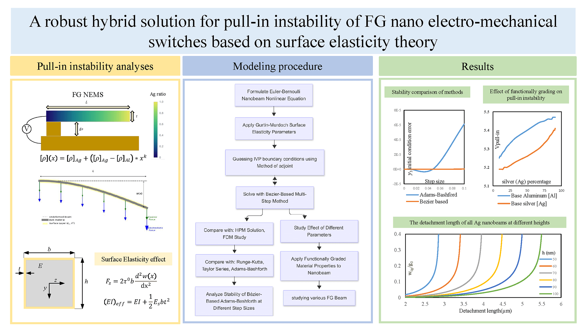
The precise computation of nanoelectromechanical switches’ (NEMS) multi-physical interactions requires advanced numerical models and is a crucial part of the development of micro- and nano-systems. This paper presents a novel compound numerical method to study the instability of a functionally graded (FG) beam-type NEMS, considering surface elasticity effects as stated by Gurtin-Murdoch theory in an Euler-Bernoulli beam. The presented method is based on a combination of the Method of Adjoints (MoA) together with the Bézier-based multi-step technique. By utilizing the MoA, a boundary value problem (BVP) is turned into an initial value problem (IVP). The resulting IVP is then solved by employing a cost-efficient multi-step process. It is demonstrated that the mentioned method can arrive at a high level of accuracy. Furthermore, it is revealed that the stability of the presented methodology is far better than that of other common multi-step methods, such as Adams-Bashforth, particularly at higher step sizes. Finally, the effects of axially functionally graded (FG) properties on the pull-in phenomenon and the main design parameters of NEMS, including the detachment length, are inspected. It was shown that the main parameter of design is the modulus of elasticity of the material, as Silver (Ag), which had better mechanical properties, showed almost a 6% improvement compared to aluminum (Al). However, by applying the correct amount of material with sturdier surface parameters, such as Aluminum (Al), at certain points, the nanobeams’ functionality can be improved even further by around 1.5%.Graphic Abstract
Keywords
Nanoelectromechanical switches (NEMS) are a class of switches that leverage the mechanical motion of a structure at the nanoscale to control the electrical current. NEMS has notable characteristics, including its diminutive size, high resonance frequencies, and relatively low volume [1,2]. They have the potential to serve as replacements for typical semiconductor switches [3], facilitate the setting up of high-speed data transmission links, and enable the development of novel sensor technologies for measuring physical properties. They provide advantages compared to regular semiconductor switches, including reduced power consumption and an increased on-off current ratio [4]. NEMS has immense potential to bring about significant changes across several fields, providing opportunities to improve various sectors substantially [5–7]. The aforementioned features of these instruments make them very suitable for a diverse range of applications, including biomedical [8] and chemical [9] sensors, automotive sensors and actuators [10], oscillators [11,12], integrated circuits [13], high-speed data transmission [14], low-power digital computing [15], logic and memory applications [16,17] and high-frequency applications [18]. However, utilizing this category of switches necessitates a highly detailed design.
The main approaches employed for the numerical investigation of mechanical characteristics in nanomaterials and nanostructures include quantum mechanics [19], atomistic simulations [20], and enriched continuum mechanics. The field of quantum mechanics is employed to examine nanomaterial structures and calculate mechanical parameters, including thermal characteristics and natural frequencies. Atomic modeling methodologies, such as molecular dynamics, are used to predict accurate physical characteristics. Atomistic simulation techniques are limited in their ability to investigate the mechanical characteristics of complex systems, and they have high calculation costs, including the behaviors of nanosystems and nanostructures [21–23]. However, the continuum model does not have the limitations mentioned in the previous methods, and a wider range of dimensions can be analyzed with it, along with less computational cost. Therefore, scholars have employed continuum modeling to investigate NEMS behaviors.
In contrast to their macroscopic counterparts, nanoscale materials and structures mainly display substantial size-dependent behavior. The behavior of materials is significantly influenced by surface elasticity at small scales. The surface area to volume ratio of a material increases considerably from the macroscopic to the nanoscale, where the surface elasticity acts markedly stronger [24]. Numerous theories, such as nonlocal elastic [25], coupled stress [26], strain gradient elastic [27], and surface elasticity [28] theories, are utilized to clarify the difference between nanoscale beam behavior and macroscale [29,30]. A stress-driven nonlocal model was introduced and applied to nanostructured beams [31]. It was later extended into the surface stress-driven model to study the coupling between long-range interactions and surface effects [32], offering improved accuracy. This modified formulation has since been the subject of recent studies investigating its effects on the mechanical behavior of nanostructured beams [33,34]. In a previous study, the NEMS beam was calculated by utilizing the non-local theory [35]. As this mechanical theory is still under scientific doubt for how the coefficients should be calculated, there is a need for the NEMS beam to be determined with a different mechanical theory. Gurtin–Murdoch surface elasticity theory [28,36] is one of the most well-known and applied theories for predicting NEMS behavior [37,38]. As a result, accurate modeling of NEMS is crucial for many of the applications mentioned and even high-frequency logic circuits and biomedical sensors, where material gradation and surface effects dominate performance. Therefore, this paper aims to utilize this surface elasticity theory as the foundation for NEMS modeling.
Currently, there is a significant interest in the study of functionally graded (FG) structures. FG beams are structural elements made from materials whose mechanical and thermal properties vary along their length or height, such as Young’s modulus, thermal conductivity, and coefficient of thermal expansion. Functional gradient materials can be fabricated using a great range of materials, including metals [39], ceramics [40], and polymers [41]. The current manufacturing methodologies for FG materials are powder metallurgy [42], chemical vapor deposition [43], laser cladding [44], and additive manufacturing [45]. FG beams possess several advantages over traditional beams, such as enhanced strength and stiffness, reduced weight, and improved thermal and electrical properties [46,47]. To provide an example [48], a fiber-reinforced composite material utilized in a thermal protection system for a spacecraft may exhibit a significantly high Young’s modulus in the area exposed to high temperatures to withstand deformation efficiently. In the other direction, in the area subjected to lower temperatures, the material may have a reduced coefficient of thermal expansion, therefore decreasing the onset of thermal stresses. A multitude of studies have investigated the integration of functionally graded materials with NEMS to construct an improved structure for switches [49–51]. The analysis of functionally graded NEMS is carried out using advanced numerical techniques because of their complex behavior.
The conversion of a boundary value problem (BVP) into an initial value problem (IVP) is typically preferred due to the relatively lower computational cost for solving an IVP compared to a BVP. One commonly used approach involves making educated guesses for the missing initial values and employing an iterative strategy to refine these initial values until the correct terminal boundaries are achieved. However, this strategy becomes inefficient when more than two initial values are unknown. This makes room for the utilization of the “Method of Adjoints,” also known as the Goodman & Lance method, which offers a more efficient alternative for determining missing initial values based on terminal values. In the case of non-linear BVPs, an iterative technique can be employed to determine the missing initial values, while linear BVPs do not necessitate iteration. This iterative approach can significantly reduce computation time by enhancing the convergence rate while maintaining a suitable accuracy [52,53].
Named after their innovator, Pierre Bézier, Bézier curves have been widely used in the structural design of automobiles since the 1960s. Aghdam et al. [54] first proposed a multi-step method based on Bézier curves to solve the initial value problems. They proved that a more stable and exact solution can be found by applying Bézier curves to several well-known nonlinear initial value problems. This method has proved useful in many mechanical systems [55–57]. In this paper, the Bézier curves-based multi-step technique is employed to compute the boundary conditions, which are used to update the MoA initial conditions. Then, common techniques such as Adams-Bashforth, Taylor, and Runge-Kutta are used to evaluate the supplied Bezier solution.
The objective of this study is to investigate the behavior of a cantilever axially functionally graded beam within NEMS by incorporating the Casimir intermolecular force. This will be achieved by applying a unique hybrid numerical approach to calculate the structural properties of the nanobeam. This numerical method is a combination of MoA and Bézier-based multi-step. More specifically, the base NEMS model is developed so that the effect of surface elasticity and FG formulations can be incorporated into the model. Then, the solution method is explained, giving details on the way MoA, along with the Bézier-based multi-step method, is implemented. The aforementioned model equations are then solved using the Bézier-based multi-step, Adams-Bashforth, Taylor, and Runge-Kutta methods and then validated. Moreover, the compatibility with the MoA of the Adams-Bashforth method is compared to the Bézier-based multi-step method. The effects of geometrical and surface elasticity parameters on the NEMS instability are investigated. Then, the FG properties of a nanobeam made of two materials are integrated into the instability analysis. Finally, the critical parameter for designing a beam-type NEMS actuator, known as the detachment length, is calculated.
Currently, our focus is on creating a model for beam-type NEMS actuators and applying the necessary forces and boundary conditions to the system. Subsequently, the surface effects will be incorporated into the equations. Then, the material properties are considered with an FG behavior.
The illustration in Fig. 1 depicts a traditional cantilever NEMS comprising two conducting electrodes that are positioned apart by a dielectric such as air or vacuum. One of the electrodes is fixed to the ground, while the other is attached to a beam that can be moved. When an electrical potential difference is imposed across the two electrodes of the switch, it generates an electrostatic force acting upon the nanobeam. Once the voltage surpasses a critical threshold, the electrostatic force experiences a proportional increase in the restoring force, leading to instability and collapse of the nanobeam towards the ground position. The phenomenon under consideration is commonly referred to as pull-in instability, and the specific electrical potential at which it occurs can also be referred to as the pull-in voltage.

Figure 1: Schematic of a cantilever-type NEMS
According to Fig. 1, a cantilever-type NEMS characterized by dimensions
The investigation primarily focuses on the static deflection of a narrow beam by utilizing the Euler-Bernoulli theory to examine the pull-in factors of NEMS.
Cases where
In the given context, the symbol
The dielectric permittivity of vacuum is
where
The utilization of a surface-layer-based model, namely a nanostructure composed of both bulk and surface components, as depicted in Fig. 2, serves as the fundamental approach for the continuous modeling of nanostructures, taking into account surface effects.

Figure 2: Schematic of a bending NEMS with surface effects
Surface effects are represented by a thin layer, denoted as
The symbol
in which
According to the information presented in Fig. 2, it can be observed that Eq. (6) demonstrates the influence of residual surface stress when the nanobeam is subjected to bending with a curvature that is not equal to zero. The distributed force applied during the bending process of NEMS can either increase or decrease their stiffness, depending on the sign of the remaining surface stress.
Considering equations for various forces as explained above, Eq. (1) can be rewritten in a more descriptive format showing the governing parameters over the nano beam as:
The boundary conditions for cantilever NEMS are given at the initial and final positions as:
2.3 Axially Functionally Graded Materials
In this study, it is assumed that the axially functionally graded (AFG) nanobeam material properties change continuously in the axial direction as a function of the component volume fractions. The functional material properties
where
Different material volume fractions are distributed along the axis
where
Initial value problems (IVPs) are generally faster to solve than boundary value problems (BVPs). One common approach is to make estimations for missing initial values and refine them using an iterative process. However, this method is less efficient, especially when multiple initial values are omitted. The “Method of Adjoints” by Goodman and Lance is highly efficient for determining unknown initial values using known terminal values. Iterative approaches can be more efficient for non-linear BVPs, while linear BVPs do not require iterative processes [53].
The initial stage of addressing the issue involves solving nth order ordinary differential equations by converting the equation into a system of n first-order differential equations. The objective of this study is to utilize the Method of Adjoints (MoA) to control the non-dimensional equation of the NEMS. As previously indicated, the initial step involves transforming Eq. (2) into a set of first-order differential equations. This is done by reestablishing the first-order differentiation of the parameter y as a new parameter, thus, the first-order differentiation of this parameter will be our second-order differentiation of y. By continuing this process, we can arrive at a system of 4 first-order differential equations shown in matrix form in Eq. (13):
where the functions
The remaining zeros in Eq. (13) are the result of turning a fourth order equation into a system of first-order equations. Considering Eq. (13), one may define a system of first-order ordinary differential equations as:
with the initial conditions as:
and the terminal conditions as:
where r and
In the MoA, the set of first-order governing differential equations is accompanied by a set of equations known as adjoint equations:
where
Therefore,
Using the set of initial conditions, we find the numerical value of this matrix at the initial point
Then, a system of adjoint equations is introduced as:
in which
The boundary conditions of adjoint equations are defined according to the boundary conditions of the original problem. For a cantilever nanobeam, two of the first initial conditions
From the solution of Eq. (24) with respect to boundary conditions (25), the following matrix can be computed:
The solution for a cantilever nanobeam may be expressed as:
The solution for a doubly clamped nanobeam can be mathematically represented as:
For the following iteration of the procedure, new initial conditions are determined based on:
The initial-value problem can be solved by employing the Bézier-based multistep method, which involves utilizing both predicted and known initial conditions. Additionally, the terminal boundary values at
3.2 Bézier-Based Multistep Method
A unique approach for solving ordinary differential equations was developed by Aghdam et al. [54] utilizing Bézier curves. Table 1 is a comprehensive compilation of the different formulations that result from each order of Bézier curves.

The mathematical representation of the
Using the Eq. (30), we can now drive different orders of the Bézier method formula. The second to fourth order can be found in Table 1.
The work presented in this paper extends the Bézier-based multistep method to solve a system of initial-boundary value problems by utilizing Bernstein polynomial basis functions. This technique is known for its robustness and effectiveness. To utilize the MoA, it is essential to generate arbitrary yet logical guesses for the absent initial conditions. While the exact value that was missing has been calculated during each iteration of the MoA, the subsequent step involves using the Bézier-based multistep approach to achieve the intended outcomes.
Therefore, to solve the Eq. (13) using the 4th order of the Bézier formula, we can drive the multistep equations:
This paper focuses mainly on the instability phenomenon of an axially beam-type FG NEMS made from silver (Ag) and aluminum (Al). MoA carried out the calculation framework as explained previously. The results below have been achieved by following the formulation of the surface elasticity theory developed for NEMS. At first, a NEMS made of silver (Ag) was verified with the results achieved by the finite difference method (FDM) and the Homotopy perturbation method (HPM) methods [59]. Then, the mentioned hybrid method is compared to 3 other multi-step methods. The methods were then relatively compared in accordance with MoA. The effect of the elasticity and geometry parameters underwent inspection. The analysis of the FG nanobeam was then carried out, which showed room for improvement.
4.1 Verification and Method Comparison
As a case study, a cantilever silver (Ag) beam has nanobeam analyzed in this section. The mechanical properties of the NEMS are as follows:
While applying the constant voltage of 1 V, the displacement of the nanobeam was calculated. This calculation was carried out by utilizing Runge-Kutta-4 as well as the 4-step formulation of Adams-Bashforth, Taylor series, and Bezier-based methods. Then, the results achieved by these methods were compared with FDM and HPM done in a previous study [59]. Table 2 demonstrates the accuracy of the methods comparatively. However, we still have to consider their stability and calculation cost.

The four-step Adams-Bashforth predictor-corrector method is an implicit method, while the other three are explicit methods. While being an explicit method, the Runge-Kutta-4 is computationally more expensive than all the methods in the present study. The Bézier-based method, which was previously explained, shows the highest stability between these methods. This matter will be discussed in more detail further in the paper.
The Adams-Bashforth method is on par with the Bézier-based method in small step sizes, while the former is a partially implicit method with a higher computation cost. It is observed that in the large step sizes, the Bézier-based method holds its stability at much larger step sizes than the Adams-Bashforth method. Table 3 shows the relative difference of tip displacement at 1 V achieved by the Adams-Bashforth and Bézier-based methods, with the average result arrived at in the FDM and HPM methods [59]. It can be said that the Bézier-based method is still accurate even in only 20 steps, while Adams-Bashforth shows large errors in less than 200 steps.

Other than stability at different step sizes, the compatibility of each method with the MoA is a crucial parameter to study. All four multi-step methods under investigation in this study were utilized with 2000 steps and 10 MoA cycles to arrive at calculate the missing initial condition. The parameter of compatibility was defined as the difference between the predicted initial condition

Figure 3: Showing MoA compatibility for each method at different step sizes
In the end, the displacements (shown

Figure 4: Comparison of displacement of the nanobeam in different methods
4.2 Instability Analysis and Geometric Effects
As seen in the NEMS analysis, there will be a voltage at which the nanobeam will become unstable; this voltage is called the pull-in voltage [10]. The pull-in voltage is the most important parameter for inspecting NEMS. This voltage can be seen in a tip displacement (shown by
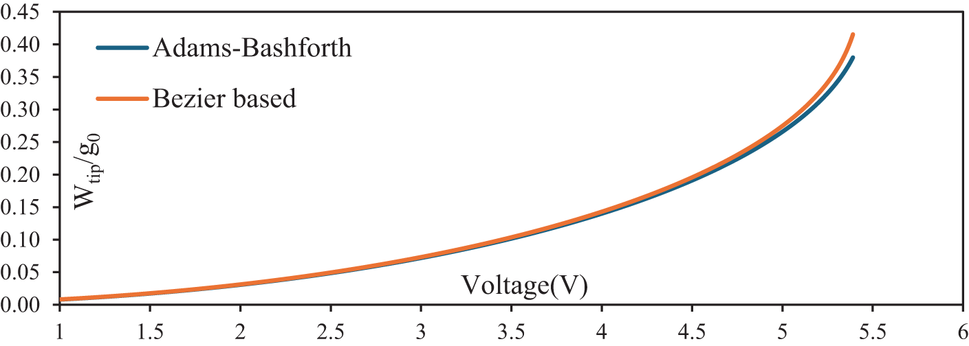
Figure 5: Displacement of NEMS tip under different voltages till the instability voltage
The first noticeable point is that the instability process usually takes place when the non-dimensional tip displacement (shown by wtip/g0) is greater than 0.41, based on the results yielded in Fig. 5. The instability voltage is a parameter that follows the nanobeam properties and initial values. As a result, the pull-in voltage (shown by

Figure 6: Instability
It can be seen in Fig. 6b that there is a direct, almost linear reaction on the instability voltage side as the height changes. This can be explained by the fact that as the height increases, the nanobeam strengthens, resulting in more nanobeam stability and a higher Vpull-in. Also, the effect of the gap change can be seen in Fig. 6a. This relationship is an even more linear one showing that the voltage of instability has an expected linear relationship.
4.3 Surface Elasticity Effects
Another aspect that can be analyzed is the effect of the surface elasticity parameters. While the difference they make in the Vpull-in may seem small, it should be noted that it is essential for the functionality of NEMS. The residual stress

Figure 7: Density plot of the effect of surface elasticity parameters on the instability voltage
4.4 Axially Functionally Graded Surface Elastic Nanobeam
The parameters of the nanobeam under analysis have now been those of a silver nanobeam. While keeping the same parameters of geometry, a new nanobeam material was analyzed. The material properties of aluminum (Al) are:
Table 4 gives a visualization of 4 nanobeams, with respectively 100%, 91%, 50%, and 9% amounts of silver (Ag) and aluminum (Al) at their base. Fig. 8 shows the percentage of silver (Ag) in all 19 different nanobeams under analysis that start with silver (Ag) at the base.


Figure 8: The silver (Ag) percentage for different amounts of the k parameter
The instability voltage diagram of the nanobeams has been analyzed and compared, and it has been illustrated for better understanding in Fig. 9.

Figure 9: Vpull-in of analyzed FG nanobeams using either Ag or Al at the base
By comparing the FG nanobeams with the fully aluminum (Al) and silver (Ag) nanobeam’s deformation at the instability voltage, it can be noted that 9%, 50%, and 91% (all in silver (Ag) amount) nanobeam starting with silver (Ag) will have respectively 5.19, 5.26, 5.41 V as their instability voltage. The same values for nanobeams starting with aluminum (Al) can be calculated as 5.25, 5.4, and 5.47 V. To understand the effect of FG nanobeams, it should be mentioned that purely silver (Ag) and aluminum (Al) had improved instability voltages of 5.39 and 5.09 V. As Fig. 9 illustrates, using an axially functionally graded nanobeam can improve our stability considerably. It is necessary to keep in mind that the nanobeam purely made of silver (Ag) reached instability at 5.39 V, which can be improved by 0.08 V by using less than 10% aluminum (Al) at the base of the nanobeam. That is a 1.5% increase while using material with a lower Young modulus, with a specific setting in the beam construction. Overall, it could be simplified to higher silver (Ag) ratios enhance stiffness at the beam enhancing the pull-in instability, while the aluminum (Al) rich regions improve the surface stress distribution.
Ultimately, the amount of deformation of an FG nanobeam can be even more significant than that of a nanobeam made of each isotropic material, which yields better results. This is due to the nature of surface elasticity parameters, as their effect is not distributed evenly through the nanobeam, and specific points-namely the importance of surface effect at the base of the nanobeam and the importance of Young modulus at the tip-in the construction of the nanobeam hold greater value than others.
Another characteristic that is necessary to consider is the detachment length of a NEMS beam. It is a primary parameter for the construction and design of the NEMS. The detachment length is defined as the maximum length at which the nanobeam does not collapse on itself with no electrostatic force and only the intermolecular forces [5].
The detachment length of the silver nanobeam previously under analysis with different heights calculated by the Bézier-based method is shown in Fig. 10a.

Figure 10: The detachment length of all Ag nanobeams at different (a) heights and (b) gap widths
This figure demonstrates the effect of heights on the statical stability of the NEMS beam. There is an almost linear relation between the two parameters. Another geometry parameter of the NEMS is the gap length. The changes in the detachment length in the 50 nm height beam made of silver (Ag) are shown in Fig. 10b.
This effect of a constructive parameter, such as the height, is more clearly shown in Fig. 11 with a comparative view of this parameter with the two methods mentioned throughout the paper.

Figure 11: All Ag nanobeam detachment lengths using both numerical methods
As it is like the effect of gap width on instability voltage, by increasing the gap width of the nanobeam, the detachment length increases in an almost linear behavior. The detachment length of these nanobeams was also analyzed for the better-performing FG nanobeams (91%) under different heights, which are illustrated in Table 5.

The way we construct the nanobeam has a significant effect on the result. However, while under electrostatic force, the instability pull-in voltage was improved, and the same cannot be said about the detachment length. This is compatible with our assumption since the detachment length is less affected by the surface effects than the pull-in phenomenon.
In the presented study, the equations of a NEMS beam underwent adjustments to be compatible with MoA. Focus was put on the comparison between Adams Bashforth and the method introduced. Both methods were thoroughly validated in comparison with recent papers and methods. Over the course of this study, it was shown the clear advantage of our mentioned method in both stability and accuracy, being more highlighted at higher step sizes.
At first, the pull-in voltage was calculated for the case of a silver (Ag) nanobeam. Moreover, the effect of the nanobeam geometrical parameters, such as gap size and nanobeam height, was compared. It was observed that these parameters have a significant impact on the instability voltage, as it increased linearly. Later, the effect of the two properties relevant to surface elasticity-namely, residual surface stress and surface elastic modulus-was considered, and the difference this theory makes in having a more accurate analysis was shown, as it can make a 7.8% increase in Vpull-in. Moreover, the study delved into the effect of using axially FG nanobeam through rigorous analysis of a nanobeam of silver (Ag) and aluminum (Al). The FG nanobeam with 89% and higher silver (Ag) present with silver (Ag) at the base of the nanobeam, and the nanobeams with 50% silver (Ag) with aluminum (Al) at the base were stable at higher voltages than the original ones. Highlighting that the nanobeam with 91% silver (Ag) with aluminum (Al) at the base was more stable by 1.5% in comparison to the purely silver (Ag) nanobeam.
This result shows potential for studies into finding optimal materials and FG nanobeams, also considering different and adjustable beam geometries such as tapered or curved nanobeams, allowing construction and modeling with even more engineerable properties. Nevertheless, for more accurate results, the study can be moved on to more detailed models, such as the non-local model, which assumes that non-local interactions are not negligible.
This research has been limited to a simple Euler-Bernoulli beam model. Yet it can open the path for deeper studies into NEMS with more advanced mechanical models such as Strain Gradient Theory or the Stress-Driven Model. Moreover, the order of accuracy of the multi-step method, unlike most others, does not decrease with using higher-order predictions, and only the stability would improve in such situations. Additionally, like many of the state-of-the-art studies in the nano field, the practical, accurate, and experimental data are lacking, resulting in an inability to verify the numerical data with non-theoretical data.
Acknowledgement: The authors thank the anonymous reviewers for their constructive feedback.
Funding Statement: The authors received no specific funding for this study.
Author Contributions: All authors confirm contribution to the paper as follows: Draft manuscript preparation: Vafa Mirzaei and Mohammad Bameri; Review the results and approve the final version of the manuscript: Mohammad Mohammadi Aghdam; Creation of images and tables: Vafa Mirzaei; Proofreading of article format: Peyman Moradweysi. All authors reviewed the results and approved the final version of the manuscript.
Availability of Data and Materials: All data generated or analyzed during this study are included in this published article.
Ethics Approval: Not applicable.
Conflicts of Interest: The authors declare no conflicts of interest to report regarding the present study.
References
1. Craighead HG. Nanoelectromechanical systems. Science. 2000;290(5496):1532–6. doi:10.1126/science.290.5496.1532. [Google Scholar] [PubMed] [CrossRef]
2. Zhang L, Xu K, Wei F. Fabrication of electronic switches based on low-dimensional nanomaterials: a review. J Mater Sci. 2023;58(5):2087–110. doi:10.1007/s10853-023-08177-0. [Google Scholar] [CrossRef]
3. Venusamy K, Tamilselvi M. Impact of NEMS technology over the growth of IoT—a analysis study. In: 2020 4th International Conference on Electronics, Communication and Aerospace Technology (ICECA); 2020 Nov 5–7; Coimbatore, India. p. 193–8. doi:10.1109/iceca49313.2020.9297582. [Google Scholar] [CrossRef]
4. Jang WW, Yoon JB, Kim MS, Lee JM, Kim SM, Yoon EJ, et al. NEMS switch with 30nm-thick beam and 20nm-thick air-gap for high density non-volatile memory applications. Solid State Electron. 2008;52(10):1578–83. doi:10.1016/j.sse.2008.06.026. [Google Scholar] [CrossRef]
5. Ilyas S, Younis MI. Resonator-based M/NEMS logic devices: review of recent advances. Sens Actuat A Phys. 2020;302:111821. doi:10.1016/j.sna.2019.111821. [Google Scholar] [CrossRef]
6. Yu X, Maalla A, Moradi Z. Electroelastic high-order computational continuum strategy for critical voltage and frequency of piezoelectric NEMS via modified multi-physical couple stress theory. Mech Syst Signal Process. 2022;165:108373. doi:10.1016/j.ymssp.2021.108373. [Google Scholar] [CrossRef]
7. Stachiv I, Alarcon E, Lamac M. Shape memory alloys and polymers for MEMS/NEMS applications: review on recent findings and challenges in design, preparation, and characterization. Metals. 2021;11(3):415. doi:10.3390/met11030415. [Google Scholar] [CrossRef]
8. Dahlan NA, Thiha A, Ibrahim F, Milić L, Muniandy S, Jamaluddin NF, et al. Role of nanomaterials in the fabrication of bioNEMS/MEMS for biomedical applications and towards pioneering food waste utilisation. Nanomaterials. 2022;12(22):4025. doi:10.3390/nano12224025. [Google Scholar] [PubMed] [CrossRef]
9. Waggoner PS, Craighead HG. Micro-and nanomechanical sensors for environmental, chemical, and biological detection. Lab Chip. 2007;7(10):1238–55. doi:10.1039/b707401h. [Google Scholar] [PubMed] [CrossRef]
10. Sparks DR. Application of MEMS technology in automotive sensors and actuators. In: MHA’98. Proceedings of the 1998 International Symposium on Micromechatronics and Human Science—Creation of New Industry; 1998 Nov 25–28; Nagoya, Japan. p. 9–15. doi:10.1109/MHS.1998.745744. [Google Scholar] [CrossRef]
11. Arndt G, Colinet E, Juillard J. Design of a co-integrated CMOS/NEMS oscillator with a simple electronic circuit. In: 2010 Symposium on Design Test Integration and Packaging of MEMS/MOEMS (DTIP); 2010 May 5–7; Seville, Spain. p. 368–71. [Google Scholar]
12. Padovani C, Pagani LG, Sansa M, Rey P, Robert P, Langfelder G. In-plane and out-of-plane FM accelerometers with 130 DB dynamic range through nems-based oscillators. In: 2024 IEEE 37th International Conference on Micro Electro Mechanical Systems (MEMS); 2024 Jan 21–25; Austin, TX, USA. p. 19–22. doi:10.1109/MEMS58180.2024.10439498. [Google Scholar] [CrossRef]
13. Dadgour HF, Banerjee K. Hybrid NEMS-CMOS integrated circuits: a novel strategy for energy-efficient designs. IET Comput Digit Tech. 2009;3(6):593–608. doi:10.1049/iet-cdt.2008.0148. [Google Scholar] [CrossRef]
14. Wei L, Kuai X, Bao Y, Wei J, Yang L, Song P, et al. The recent progress of MEMS/NEMS resonators. Micromachines. 2021;12(6):724. doi:10.3390/mi12060724. [Google Scholar] [PubMed] [CrossRef]
15. Peschot A, Qian C, Liu TJ. Nanoelectromechanical switches for low-power digital computing. Micromachines. 2015;6(8):1046–65. doi:10.3390/mi6081046. [Google Scholar] [CrossRef]
16. Song YH, Yoon JB. Micro and nanoelectromechanical contact switches for logic, memory, and power applications. In: Kyung CM, editor. Nano devices and circuit techniques for low-energy applications and energy harvesting. Dordrecht, The Netherlands: Springer; 2015. p. 65–117. doi:10.1007/978-94-017-9990-4_3. [Google Scholar] [CrossRef]
17. Wang Z, Fang J, Zhang P, Yang R. Nanomechanics: emerging opportunities for future computing. Sci China Inf Sci. 2021;64(10):206401. doi:10.1007/s11432-020-3241-9. [Google Scholar] [CrossRef]
18. Kaul AB, Wong EW, Epp L, Hunt BD. Electromechanical carbon nanotube switches for high-frequency applications. Nano Lett. 2006;6(5):942–7. doi:10.1021/nl052552r. [Google Scholar] [PubMed] [CrossRef]
19. Słowik O, Orłowska K, Kopiec D, Janus P, Grabiec P, Gotszalk T. Quantum mechanical aspects in the MEMS/NEMS technology. Meas Autom Monit. 2016;62(3):87–91. [Google Scholar]
20. Klimeck G, Ahmed SS, Bae H, Kharche N, Clark S, Haley B, et al. Atomistic simulation of realistically sized nanodevices using NEMO 3-D—part I: models and benchmarks. IEEE Trans Electron Devices. 2007;54(9):2079–89. doi:10.1109/TED.2007.902879. [Google Scholar] [CrossRef]
21. Fakhrabadi MMS, Amini A, Reshadi F, Khani N, Rastgoo A. Investigation of buckling and vibration properties of hetero-junctioned and coiled carbon nanotubes. Comput Mater Sci. 2013;73:93–112. doi:10.1016/j.commatsci.2013.02.020. [Google Scholar] [CrossRef]
22. Fakhrabadi MMS, Amini A, Rastgoo A. Vibrational properties of two and three junctioned carbon nanotubes. Comput Mater Sci. 2012;65:411–25. doi:10.1016/j.commatsci.2012.08.002. [Google Scholar] [CrossRef]
23. Fakhrabadi MMS, Allahverdizadeh A, Norouzifard V, Dadashzadeh B. Effects of boron doping on mechanical properties and thermal conductivities of carbon nanotubes. Solid State Commun. 2012;152(21):1973–9. doi:10.1016/j.ssc.2012.08.003. [Google Scholar] [CrossRef]
24. Mohebshahedin A, Farrokhabadi A. The influence of the surface energy on the instability behavior of NEMS structures in presence of intermolecular attractions. Int J Mech Sci. 2015;101:437–48. doi:10.1016/j.ijmecsci.2015.08.017. [Google Scholar] [CrossRef]
25. Eringen AC. On differential equations of nonlocal elasticity and solutions of screw dislocation and surface waves. J Appl Phys. 1983;54(9):4703–10. doi:10.1063/1.332803. [Google Scholar] [CrossRef]
26. Yang F, Chong ACM, Lam DCC, Tong P. Couple stress based strain gradient theory for elasticity. Int J Solids Struct. 2002;39(10):2731–43. doi:10.1016/S0020-7683(02)00152-X. [Google Scholar] [CrossRef]
27. Mindlin RD. Second gradient of strain and surface-tension in linear elasticity. Int J Solids Struct. 1965;1(4):417–38. doi:10.1016/0020-7683(65)90006-5. [Google Scholar] [CrossRef]
28. Gurtin ME, Murdoch AI. Surface stress in solids. Int J Solids Struct. 1978;14(6):431–40. doi:10.1016/0020-7683(78)90008-2. [Google Scholar] [CrossRef]
29. Moradweysi P, Ansari R, Hosseini K, Sadeghi F. Application of modified Adomian decomposition method to pull-in instability of nano-switches using nonlocal Timoshenko beam theory. Appl Math Model. 2018;54(9):594–604. doi:10.1016/j.apm.2017.10.011. [Google Scholar] [CrossRef]
30. Abdi J, Koochi A, Kazemi AS, Abadyan M. Modeling the effects of size dependence and dispersion forces on the pull-in instability of electrostatic cantilever NEMS using modified couple stress theory. Smart Mater Struct. 2011;20(5):055011. doi:10.1088/0964-1726/20/5/055011. [Google Scholar] [CrossRef]
31. Romano G, Barretta R. Nonlocal elasticity in nanobeams: the stress-driven integral model. Int J Eng Sci. 2017;115(5):14–27. doi:10.1016/j.ijengsci.2017.03.002. [Google Scholar] [CrossRef]
32. Penna R. Bending analysis of functionally graded nanobeams based on stress-driven nonlocal model incorporating surface energy effects. Int J Eng Sci. 2023;189(12):103887. doi:10.1016/j.ijengsci.2023.103887. [Google Scholar] [CrossRef]
33. Lovisi G, Feo L, Lambiase A, Penna R. Application of surface stress-driven model for higher vibration modes of functionally graded nanobeams. Nanomaterials. 2024;14(4):350. doi:10.3390/nano14040350. [Google Scholar] [PubMed] [CrossRef]
34. Penna R, Lovisi G, Feo L. Buckling analysis of functionally graded nanobeams via surface stress-driven model. Int J Eng Sci. 2024;205(2):104148. doi:10.1016/j.ijengsci.2024.104148. [Google Scholar] [CrossRef]
35. Bameri M, Mirzaei V, Moradweysi P, Aghdam MM. A hybrid numerical study of the nonlinear instability of nano-switches. In: Jazar RN, Dai L, editors. Nonlinear approaches in engineering application. Cham, Switzerland: Springer; 2024. p. 295–318. doi:10.1007/978-3-031-53582-6_10. [Google Scholar] [CrossRef]
36. Gurtin ME, Ian Murdoch A. A continuum theory of elastic material surfaces. Arch Ration Mech Anal. 1975;57(4):291–323. doi:10.1007/BF00261375. [Google Scholar] [CrossRef]
37. Mahmoud FF, Eltaher MA, Alshorbagy AE, Meletis EI. Static analysis of nanobeams including surface effects by nonlocal finite element. J Mech Sci Technol. 2012;26(11):3555–63. doi:10.1007/s12206-012-0871-z. [Google Scholar] [CrossRef]
38. Fu Y, Zhang J. Size-dependent pull-in phenomena in electrically actuated nanobeams incorporating surface energies. Appl Math Model. 2011;35(2):941–51. doi:10.1016/j.apm.2010.07.051. [Google Scholar] [CrossRef]
39. Ghanavati R, Naffakh-Moosavy H. Additive manufacturing of functionally graded metallic materials: a review of experimental and numerical studies. J Mater Res Technol. 2021;13(1–2):1628–64. doi:10.1016/j.jmrt.2021.05.022. [Google Scholar] [CrossRef]
40. Li W, Armani A, Martin A, Kroehler B, Henderson A, Huang T, et al. Extrusion-based additive manufacturing of functionally graded ceramics. J Eur Ceram Soc. 2021;41(3):2049–57. doi:10.1016/j.jeurceramsoc.2020.10.029. [Google Scholar] [CrossRef]
41. Singh S, Dwivedi UK, Chandra Shukla S. Recent advances in polymer based functionally graded composites. Mater Today Proc. 2021;47(2):3001–5. doi:10.1016/j.matpr.2021.05.324. [Google Scholar] [CrossRef]
42. Tripathy A, Sarangi SK, Panda R. Fabrication of functionally graded composite material using powder metallurgy route: an overview. Int J Mech Prod Eng Res Dev. 2017;7(6):135–45. doi:10.1007/978-981-32-9471-4_62. [Google Scholar] [CrossRef]
43. Groves JF, Wadley HNG. Functionally graded materials synthesis via low vacuum directed vapor deposition. Compos Part B Eng. 1997;28(1–2):57–69. doi:10.1016/S1359-8368(96)00023-6. [Google Scholar] [CrossRef]
44. Abboud JH, Rawlings RD, West DRF. Functionally graded nickel-aluminide and iron-aluminide coatings produced via laser cladding. J Mater Sci. 1995;30(23):5931–8. doi:10.1007/BF01151508. [Google Scholar] [CrossRef]
45. Li Y, Feng Z, Hao L, Huang L, Xin C, Wang Y, et al. A review on functionally graded materials and structures via additive manufacturing: from multi-scale design to versatile functional properties. Adv Mater Technol. 2020;5(6):1900981. doi:10.1002/admt.201900981. [Google Scholar] [CrossRef]
46. Reddy JN, Ruocco E, Loya JA, Neves AMA. Theories and analysis of functionally graded beams. Appl Sci. 2021;11(15):7159. doi:10.3390/app11157159. [Google Scholar] [CrossRef]
47. Kumar V, Akkasali NK, Kumar EK, Panda SK. Applications of functionally graded nano-and microstructures in MEMS and NEMS. In: Jena SK, Pradyumna S, Chakraverty S, editors. Advances in modelling and analysis of functionally graded micro-and nanostructures. Bristol, UK: IOP Publishing; 2024. p. 8–19. doi:10.1088/978-0-7503-6024-1ch8. [Google Scholar] [CrossRef]
48. Kumar S, Murthy Reddy KVVS, Kumar A, Rohini Devi G. Development and characterization of polymer-ceramic continuous fiber reinforced functionally graded composites for aerospace application. Aerosp Sci Technol. 2013;26(1):185–91. doi:10.1016/j.ast.2012.04.002. [Google Scholar] [CrossRef]
49. Fan F, Lei B, Sahmani S, Safaei B. On the surface elastic-based shear buckling characteristics of functionally graded composite skew nanoplates. Thin Walled Struct. 2020;154:106841. doi:10.1016/j.tws.2020.106841. [Google Scholar] [CrossRef]
50. Fattahi AM, Sahmani S, Ahmed NA. Nonlocal strain gradient beam model for nonlinear secondary resonance analysis of functionally graded porous micro/nano-beams under periodic hard excitations. Mech Based Des Struct Mach. 2020;48(4):403–32. doi:10.1080/15397734.2019.1624176. [Google Scholar] [CrossRef]
51. Sahmani S, Safaei B. Influence of homogenization models on size-dependent nonlinear bending and postbuckling of bi-directional functionally graded micro/nano-beams. Appl Math Model. 2020;82:336–58. doi:10.1016/j.apm.2020.01.051. [Google Scholar] [CrossRef]
52. Roberts SM, Shipman JS. Two-point boundary value problems: shooting methods. New York, NY, USA: Elsevier; 1972. [Google Scholar]
53. Goodman TR, Lance GN. The numerical integration of two-point boundary value problems. Math Tables Other Aids Comput. 1956;10(54):82. doi:10.2307/2002181. [Google Scholar] [CrossRef]
54. Aghdam MM, Fallah A, Haghi P. Nonlinear initial value ordinary differential equations. In: Dai L, Jazar RN, editors. Nonlinear approaches in engineering applications. Cham, Switzerland: Springer International Publishing; 2014. p. 117–36. doi:10.1007/978-3-319-09462-5_5. [Google Scholar] [CrossRef]
55. Kabir H, Aghdam MM. A robust Bézier based solution for nonlinear vibration and post-buckling of random checkerboard graphene nano-platelets reinforced composite beams. Compos Struct. 2019;212(1):184–98. doi:10.1016/j.compstruct.2019.01.041. [Google Scholar] [CrossRef]
56. Kabir H, Aghdam MM. A generalized 2D Bézier-based solution for stress analysis of notched epoxy resin plates reinforced with graphene nanoplatelets. Thin Walled Struct. 2021;169(1):108484. doi:10.1016/j.tws.2021.108484. [Google Scholar] [CrossRef]
57. Heydarpour Y, Aghdam MM. A hybrid Bézier based multi-step method and differential quadrature for 3D transient response of variable stiffness composite plates. Compos Struct. 2016;154:344–59. doi:10.1016/j.compstruct.2016.07.060. [Google Scholar] [CrossRef]
58. Serry FM, Walliser D, Maclay GJ. The anharmonic Casimir oscillator (ACO)-the Casimir effect in a model microelectromechanical system. J Microelectromech Syst. 1995;4(4):193–205. doi:10.1109/84.475546. [Google Scholar] [CrossRef]
59. Ma JB, Jiang L, Asokanthan SF. Influence of surface effects on the pull-in instability of NEMS electrostatic switches. Nanotechnology. 2010;21(50):505708. doi:10.1088/0957-4484/21/50/505708. [Google Scholar] [PubMed] [CrossRef]
60. Huang JM, Liew KM, Wong CH, Rajendran S, Tan MJ, Liu AQ. Mechanical design and optimization of capacitive micromachined switch. Sens Actuat A Phys. 2001;93(3):273–85. doi:10.1016/S0924-4247(01)00662-8. [Google Scholar] [CrossRef]
61. Gupta RK. Electrostatic pull-in test structure design for in-situ mechanical property measurements of microelectromechanical systems (MEMS) [dissertation]. Cambridge, MA, USA: Massachusetts Institute of Technology; 1997. [Google Scholar]
62. Israelachvili JN. Intermolecular and surface forces. 3rd ed. Burlington, MA, USA: Academic Press; 2011. [Google Scholar]
63. Lamoreaux SK. The Casimir force: background, experiments, and applications. Rep Prog Phys. 2005;68(1):201–36. doi:10.1088/0034-4885/68/1/r04. [Google Scholar] [CrossRef]
64. Miller RE, Shenoy VB. Size-dependent elastic properties of nanosized structural elements. Nanotechnology. 2000;11(3):139–47. doi:10.1088/0957-4484/11/3/301. [Google Scholar] [CrossRef]
65. Wang GF, Feng XQ. Surface effects on buckling of nanowires under uniaxial compression. Appl Phys Lett. 2009;94(14):141913. doi:10.1063/1.3117505. [Google Scholar] [CrossRef]
66. Jones RM. Mechanics of composite materials. Boca Raton, FL, USA: CRC Press; 2018. [Google Scholar]
Cite This Article
 Copyright © 2025 The Author(s). Published by Tech Science Press.
This work is licensed under a Creative Commons Attribution 4.0 International License , which permits unrestricted use, distribution, and reproduction in any medium, provided the original work is properly cited.
 Downloads
 Citation Tools