
 Submit a Paper
 Propose a Special lssue
 Open Access
ARTICLE
Sharp Interface Establishment through Slippery Fluid in Steady Exchange Flows under Stratification
1 Department of Mathematics, Hacettepe University, Beytepe, Ankara, 06532, Türkiye
2 Department of Medical Research, China Medical University Hospital, China Medical University, Taichung, 40402, Taiwan
3 Industrial Engineering Department, Faculty of Engineering, University of Tabuk, Tabuk, 71491, Saudi Arabia
* Corresponding Author: Mustafa Turkyilmazoglu. Email:
Computer Modeling in Engineering & Sciences 2025, 143(3), 2847-2865. https://doi.org/10.32604/cmes.2025.068031
Received 19 May 2025; Accepted 13 June 2025; Issue published 30 June 2025
 View Full Text
 Download PDF
Abstract
The variable salinity in stored reservoirs connected by a long channel attracts the attention of scientists worldwide, having applications in environmental and geophysical engineering. This study explores the impact of Navier slip conditions on exchange flows within a long channel connecting two large reservoirs of differing salinity. These horizontal density gradients drive the flow. We modify the recent one-dimensional theory, developed to avoid runaway stratification, to account for the presence of uniform slip walls. By adjusting the parameters of the horizontal density gradient based on the slip factor, we resolve analytically various flow regimes ranging from high diffusion to transitional high advection. These regimes are governed by physical parameters like channel aspect ratio, slip factor, Schmidt number, and gravitational Reynolds number. Our solutions align perfectly with ones in the no-slip limit. More importantly, under the conditions of no net flow across the channel and high Schmidt number (where stratification is concentrated near the channel’s mid-layer), we derive a closed-form solution for the slip parameter, aspect ratio, and gravitational Reynolds number that describes the interface’s behavior as a sharp interface separating two distinct zones. This interface, arising from hydrostatic wall gradients, ultimately detaches the low- and high-density regimes throughout the channel when the gravitational Reynolds number is inversely proportional to the aspect ratio for a fixed slip parameter. This phenomenon, observed previously in 2D numerical simulations with no-slip walls in the literature, is thus confirmed by our theoretical results. Our findings further demonstrate that wall slip leads to distinct and diverse flow regimes.Keywords
The sea and ocean represent classic examples of environmental flowswhere buoyancy-driven exchange occurs due to varying densities within the seawater mixture [1–3]. These exchange flows, also known as stratified shear flows, and their hydrodynamics governed by density stratification have attracted significant research due to their impact on nature in both oceanic and other geophysical contexts. Examples include the Bosphorus straits [4], estuary dynamics [5], architectural exchange flows [6], reservoir optimization for flood control [7], flooded underground mines [8], and understanding stratified turbulence [9]. This study focuses on these exchange phenomena within slippery walls, considering both scenarios with and without an interface separating the lighter and heavier water columns.
Thermal or solutal stratification may occur in vast engineering problems with different physical configurations. To focus on the recent efforts associated with the environmental research, estuarine exchange flow was reformulated in [10] accounting for the influence of wind forcing in the model, and methods were established for estimating estuarine stratification and flushing time in U.S. continental [11]. It was observed in the case study [12] that the thermocline and high-salt area can limit the water exchange in Western Pacific Ocean. Reference [13] presented how the deep hydrography in the subarctic Pacific evolves affecting the subtropical Pacific under glacial boundary conditions. The conditions of lake stratification in the Brazilian Amazon were examined in [14]. The impacts of the wind, tidal forcing, freshwater discharge and the bay stratification were searched in [15] for the coast of Peru. Hypoxia was detected in [16] due to the vertical salinity structure and high temperature in Saemangeum Lake.
In regard to the technological energy storage systems, the water stratification and thermocline dynamics in solar hot water storage tanks with mantle heat exchangers were experimentally tested in [17]. It was shown in [18] that a single media single tank system is better performing with a porous structure of the distributor wall during thermal energy storage. Flow injection effects on the temperature stratification in thermocline storage tanks were simulated in [19] with the aim of determining the stability range of bulk Froude number. Moreover, the stratification performance was numerically simulated in [20] in a packed-bed thermal storage tank.
In terms of other relevant applications, thermal stratification dependence on mass flow rate of coolant in nuclear reactors was numerically simulated in [21]. It was also determined in [22] that stable temperature stratification due to high-rise buildings can aggravate pollutant concentration in urban areas. One can further refer to other more mathematically inclined applications including [23–25], amongst many others.
The formulation of the driving force due to the horizontal difference in densities seems to be the hardest part of mathematical models in the real exchange flows. Reference [1] developed a connection between the horizontal density gradient and density/vertical density to be used in the balanced equations of diffusion of both momentum and density enabling one to learn the flow regime transitions. In high density transport region, a sharp interface of prevention between the two-phase system was clearly witnessed from the 2D numerical visualizations in [1]. Earlier, based on the internal hydraulics limit concept, such an interfacial depth derivation was implemented in [26] for the two-layer salinity system in a long duct. However, the very current experimental conduct in [27] proved that the free-slip and sharp non-entraining interface should be in account of a correct Froude number at the front. More research regarding bioconvection and density variation in fluid and heat flow was reported in [28,29]. The use of artificial intelligence techniques in various slippery fluid flows over channel configurations was also documented in [30,31].
This study builds upon the promising 1D no-slip model presented in [1] for estimating velocity and density fields in various steady flow regimes between two large tanks. However, recent experiments by [27] suggest that imposing free-slip conditions provides a more realistic representation of such phenomena. Therefore, our primary focus here is to understand how the observed flow regimes in Kaptein et al.’s work are significantly influenced by the presence of velocity slip at the channel walls connecting the reservoirs. Even though, the standard boundary condition for fluid-solid interfaces is the no-slip condition, the presence of tiny wall roughnesses does not disturb the channel shape, or surface treatment, or near-wall phenomena in complex fluids adequately justifies the use of a Navier-slip condition at the fluid-solid interface. Indeed, the importance of slippery walls have been well-recognized now among the scientific community. One can refer to the natural life applications in [32] and other micro channel applications in [33,34]. While study [1] primarily focused on parameter ranges leading to interface waves, another objective of this work is to formulate the exact boundary/interface that emerges between the fresher and saltier fluid zones during the high advection unmixed density transport stage (observed in Kaptein et al.’s numerical simulations). This phenomenon, occurring when density diffusion is overpowered by viscous fluid diffusion, manifests as a sharp, solid interface separating the pure fresher water flow above from the pure saltier water below. By balancing the diffusive and hydrostatic terms, we derive a mathematical function for this interface that incorporates the slip parameter. This investigation has the potential to enhance our understanding of real-world ocean dynamics, such as salt fronts in estuaries, and the resulting analytical expressions can offer valuable insights for numerical simulations of oceanic fronts.
2 Stratification Model between Two Reservoirs
As depicted in Fig. 1, we consider steady exchange flow motion owing to an active buoyancy force, where the less dense (light) mixture of water flows over a high dense (heavy) mixture through a horizontal channel connecting two huge reservoirs. The exchange takes place due to the salinity difference yielding distinct densities in the tanks, which are attached via a channel having length L and height H, supposedly much smaller than L. Having balanced the diffusion of momentum and salt with density gradient (horizontal), a steady state flow is reached, whose governing equations under the Boussinesq approximation are given by
in which
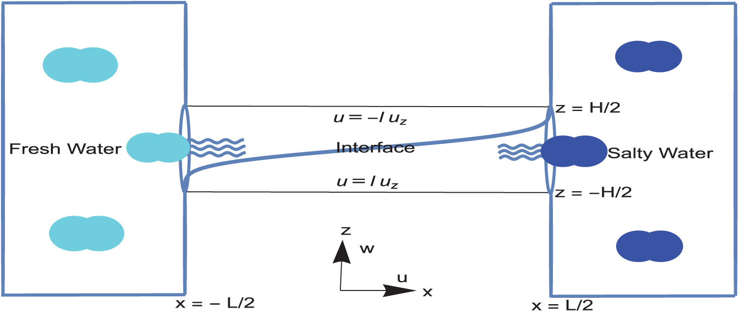
Figure 1: Stratification process between two huge reservoirs of water containing different salt concentrations. Fluid is flowing through a slippery long and thin channel having a small aspect ratio
Salinity and density can further be linked via a linear relation as in [1], but not preferred here. With respect to a defined buoyancy velocity scale
Having dropped the tilde from the quantities for convenience, and substituting (2) into (1) leads to the non-dimensional system
The dimensionless physical parameters in (3) governing the physical process are defined by
where
The physical domain along the channel is now
As stated above, the very current experimental conducts in [27] revealed that the free-slip and sharp non-entraining interface should be in account of a correct Froude number at the front. This motivated [27] to apply the free-slip boundary conditions at the fluid-fluid interface, in the stratified fluid treated as a two-layer system. It is highly believed that the current slip condition will complement the fluid-fluid slip assumption made in [27] and the theory is completed within the slippery conditions at both fluid-fluid and solid-fluid interfaces. It is noted that if the slip velocity arises due to wall roughness, the typical values of the dimensionless slip length L scaled by
The condition in 6 will assist occurrence of a physical asymmetry along the channel.
Closely following the fundamental assumptions in [1], such as the no effect of the reservoir with endless amount of fresh water and salt, the small aspect ratio with sufficiently long channel leading to a boundary layer effect of dropping the diffusive gradients along the channel, a unidirectional flow particularly effective in the central zone
We should remark that the mathematical analysis made under the no-slip boundary conditions in [1] in the central region of the channel is still valid here when slip is accounted for. Indeed, integrating the second momentum equation in (7) from
where
The problem is then reduced to the prescription of radial mass transport
The solution to (10) comes with the formulae
The
which drives the density along with the total mixture
From the above results, at the wall in the mid layer the accumulated salt densities yield the stratification amplitude
with
In the advection-dominated zone, however,
With this density distribution, having solved the system (7) results in the slip velocity field
Presuming that the wall stress at
overlapping the value
and thus the horizontal density change in combination with the above pressure field driving the exchange flow and stratification as proposed in [1] can be generalized here incorporating the velocity slip in the form
Consequently, the interface slope at
This result specifically helps us to set the idea that there exists an interface
Notice that with piece-wisely defined density distribution as above in mind, the density transport equation in (22) is already satisfied in each layer. Solution of system (22) yields the horizontal and vertical velocities across the interface
where
where
Moreover, this should be equal to the following pressure gradient obtained from the volume flow rate definition across the interface
It is apparent then that the mixture of flow is driven by a pressure gradient involving gradients of interface as well as the hydrostatic pressure. Hence, Eqs. (26) and (27) give rise to the following differential equation describing the shape of interface
One of the significant features of the interface is that vertical asymptotes are reached at the edges where
for which the intermediate parameters are listed in the Appendix A. It is reminded that the interface lies from the first reservoir up to the second reservoir if
which turns out to be in the case of
This corresponds to a gravitational Reynolds number
The results of velocity, density, and pressure fields will be presented in this section in competing diffusive and advective regimes of the exchange flow governed by the physical parameters L,
In the high diffusion regime, the scaled horizontal velocity and density profiles are shown in Fig. 2 drawn from (11). The asymmetry in both is due to the physical reason that the dense salt layer moving towards the reservoir of fresh water is balanced with the less dense layer counter flowing towards the salty reservoir induced by the horizontal pressure gradient in (12). This pressure gradient is not affected by the slip, but the vertical pressure gradient is highly controlled by it, which in turn balances the density distribution. The velocity slip is expectedly to increase the momentum transfer drifts as well as the mass over the depth of the channel, both of which are raised with a larger amplitude near the walls, hence the high stratification of mixture near
at the vertical positions
with the resultant wall densities
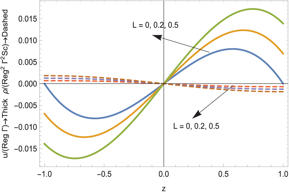
Figure 2: The scaled horizontal velocity and density profiles in high diffusion zone; unbroken curves for velocity and broken for density
The absolute volumetric flow rate and mass flow rate are also computed from
The shear and density gradients in this regime at the mid-depth
which indicates the increase in gradients with the slip. The stratification and exchange flow amplitudes from (14), (15) are demonstrated in Fig. 3a,b. They are shown to be impacted by the presence of velocity wall slip. A linear increase in stratification is certainly conserved. It is recalled that these physical quantities are predicted well by the 1D theory in a small
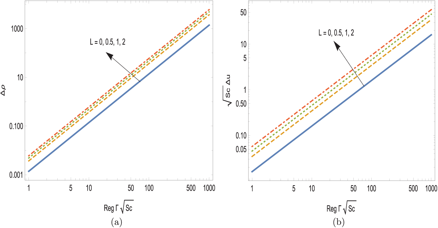
Figure 3: Effects of slip on the amplitudes. (a) Stratification and (b) exchange flow
In the particular case of no-slip flow, it means
Scaled velocity profiles are next revealed in Fig. 4 in the high advection zone from (17). Recall that in this zone, the density is already in its highest values
at the locations
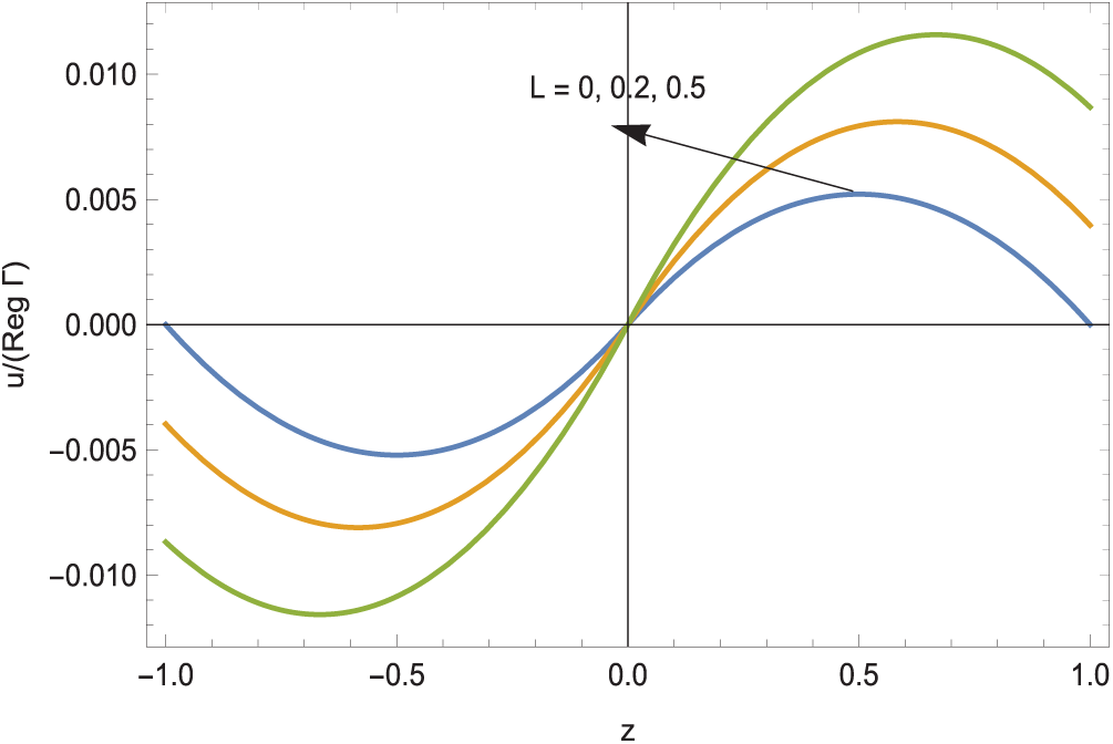
Figure 4: The scaled horizontal velocity profiles in high advection zone
The absolute volumetric flow rate is also computed from
The fluid is under the influence of linear pressure (19), which generates a slightly less momentum layer thickness as compared to the high diffusion regime.
The formation of a sharp interface separating two layers will be deliberated now from the derivations (22)–(32). Actually, Fig. 5 depicts the critical combination of
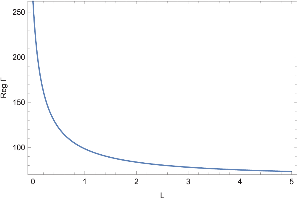
Figure 5: Critical
Fig. 6 then exhibits the effect of slip on the structure of the interface
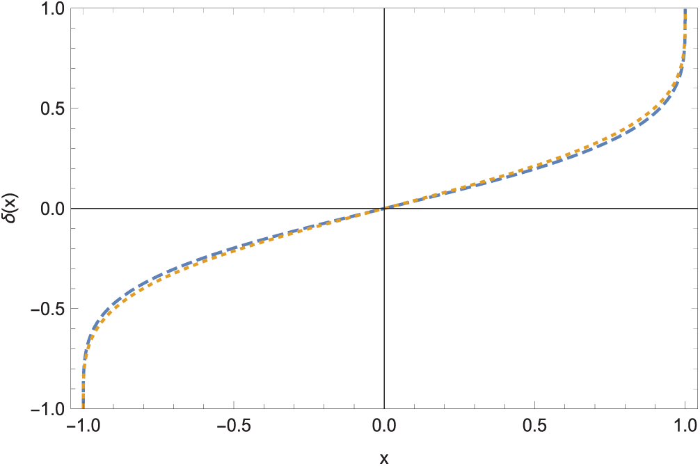
Figure 6: Interface shape at two slip parameters; dashed
Remarkably
It is noted that if the interface is not necessarily required to extend from reservoir to reservoir, then any
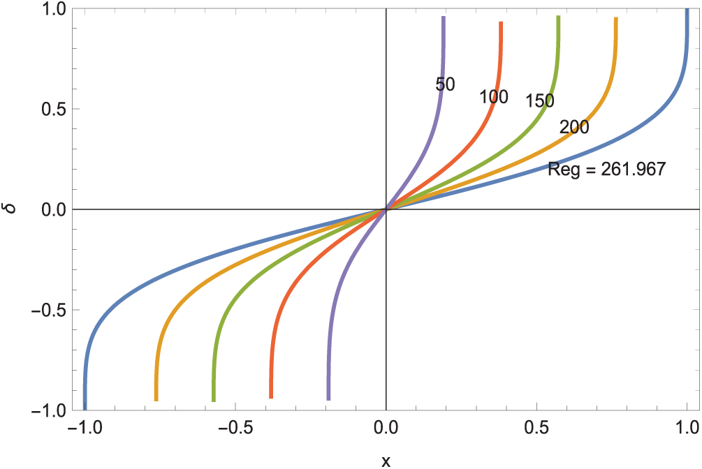
Figure 7: Interface shapes with no slip for changing
Fig. 8a–d illustrates the horizontal and vertical velocity profiles across the interface from (23), (24) in the high advection regime at the instant of interface formation. In the presence of the interface layer, the streamwise local extrema and exchange flow amplitude from the horizontal velocity field are calculated as
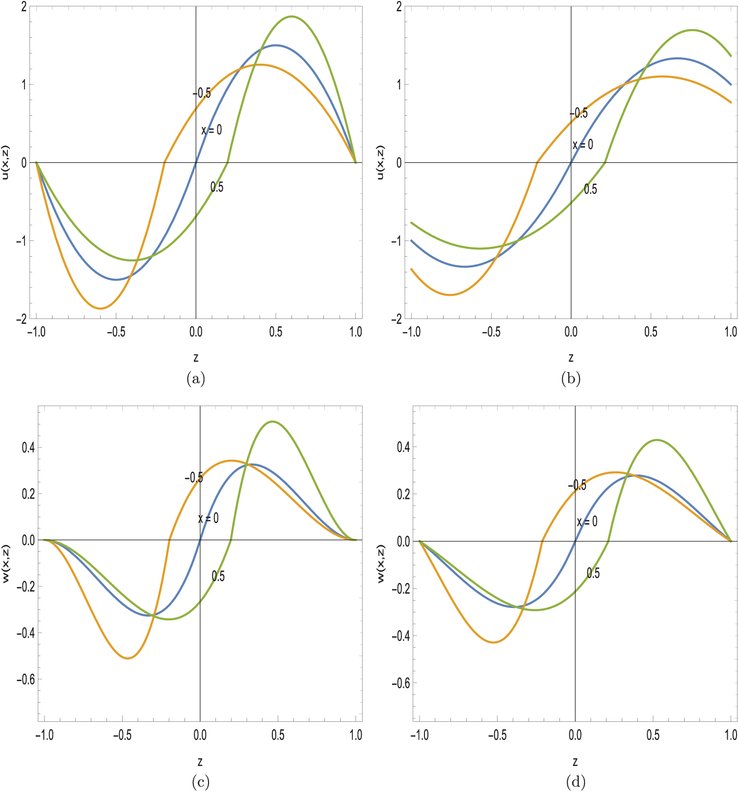
Figure 8: Velocity fields across the interface.
Even though the velocity distributions are symmetric at the centre of the channel from Fig. 8a–d, proceeding horizontally leads to redistribution of the velocities balanced with increasing/decreasing peaks at the depicted streamwise locations, due to the conservation of momentum. Interestingly, slip is seen to slightly reduce the extremums in (37), unlike the previous results in Figs. 2 and 4.
Additionally, the velocities of light and heavy particles at the entrance of the channel from the reservoirs are calculated from
whose profiles are exhibited in Fig. 9a,b. Although, figures give a clear physical intuition of how diffusion happens, a more rigorous analysis is required to explore the entrance regions as in [35].
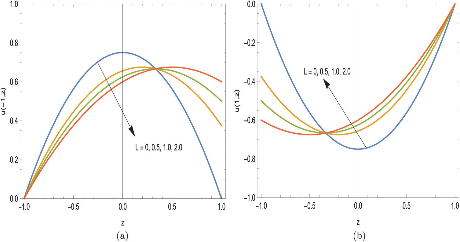
Figure 9: Velocity profiles at the channel entry. (a)
It is worthy of pointing that the interfacial zone is formed under the pressure defined in (25). Moreover, the pressure P from (26) or (27) can be integrated analytically in terms of
It is also noted that
Typical hydrostatic pressure distributions are revealed in Fig. 10. Equal volume flow rates across the interface leads to a symmetric pressure distribution, which in turn assists in the formation of sharp interface itself.
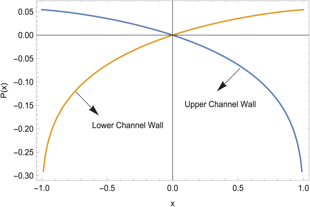
Figure 10: Pressures at the channel boundary
The pressure at the interface for no-slip can eventually be evaluated from (25) making use of (39)
which is illustrated in Fig. 11. Clearly, the slip triggered interfaces as demonstrated in Fig. 6 are balanced as a result of slight modifications of pressures above.
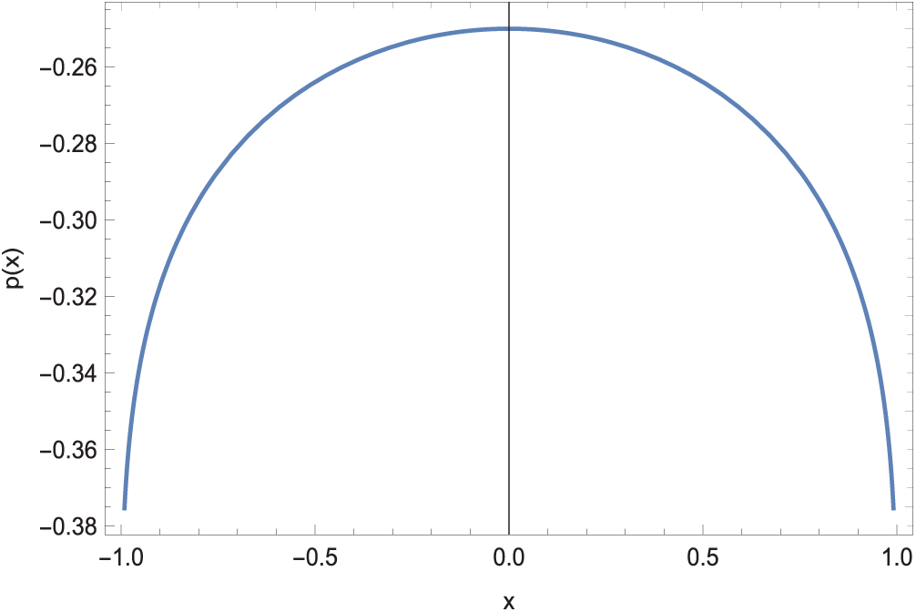
Figure 11: Pressure at the interface
This paper analytically investigates the potential impacts of velocity slip on stratified laminar exchange flows driven by density differences between two large tanks. We extend the one-dimensional no-slip model developed in [1] to incorporate Navier’s velocity slip law at the wall surfaces of the channel connecting the tanks of differing salinity. Our focus lies on the highly diffusive and highly advective flow regimes.
Our derived analytical expressions depend on four key physical parameters: channel aspect ratio, slip factor, Schmidt number, and gravitational Reynolds number. Notably, our solutions replicate those of [1] for the no-slip case. Furthermore, we find that slip generally increases velocity and density distributions in the high diffusion zone, thereby extending stratification and amplifying the exchange flow amplitude.
We also investigate the sharp interface arising in the high advection zone, which completely separates the low- and high-density exchange flows. An exact solution reveals that this interface forms due to a balance of hydrostatic pressure gradients acting on the channel walls under the no net flow assumption. Additionally, imposing the interface condition restricts the gravitational Reynolds number to be inversely proportional to the aspect ratio for a fixed slip parameter. This formula closely matches the interface observed in [1] high advection no-slip numerical simulations.
While velocity slip slightly modifies the interface, leading to a rearrangement of flow patterns above and below, its effect differs distinctly from that in the high diffusion zone. Notably, the parameter space leading to runaway stratification in certain flow regimes, as predicted by our one-dimensional model, warrants further study using 2D numerical simulations. Such simulations would enable better visualization and verification of the overall effects of the slip mechanism. The investigation of possible complexities introduced if a wavy boundary was used for the reservoir or if a Darcy porous medium was used in the reservoir would warrant further research.
Acknowledgement: Not applicable.
Funding Statement: None.
Author Contributions: The authors confirm contribution to the paper as follows: Conceptualization, Mustafa Turkyilmazoglu; methodology, Mustafa Turkyilmazoglu; software, Mustafa Turkyilmazoglu and Abdulaziz Alotaibi; validation, Mustafa Turkyilmazoglu and Abdulaziz Alotaibi; formal analysis, Mustafa Turkyilmazoglu and Abdulaziz Alotaibi; investigation, Mustafa Turkyilmazoglu and Abdulaziz Alotaibi; resources, Mustafa Turkyilmazoglu; data curation, Mustafa Turkyilmazoglu; writing—original draft preparation, Mustafa Turkyilmazoglu; writing—review and editing, Mustafa Turkyilmazoglu and Abdulaziz Alotaibi; visualization, Mustafa Turkyilmazoglu and Abdulaziz Alotaibi; supervision, Mustafa Turkyilmazoglu; project administration, Mustafa Turkyilmazoglu; funding acquisition, Mustafa Turkyilmazoglu. All authors reviewed the results and approved the final version of the manuscript.
Availability of Data and Materials: Data and materials can be obtained from the corresponding author upon a reasonable request.
Ethics Approval: Not applicable.
Conflicts of Interest: The authors declare no conflicts of interest to report regarding the present study.
Dummy variables are defined as follows:
References
1. Kaptein SJ, van de Wal KJ, Kamp LPJ, Armenio V, Clercx HJH, Duran-Matute M. Analysis of one-dimensional models for exchange flows under strong stratification. Ocean Dyn. 2020;70(1):41–56. doi:10.1007/s10236-019-01320-z. [Google Scholar] [CrossRef]
2. Maderich VS, Konstantinov SI, Kulik AT, Oleksiuk VV. Laboratory modelling of the water exchange through the sea straits. Oceanology. 1998;38:602–8. [Google Scholar]
3. Hogg A, Ivey G, Winters K. Hydraulics and mixing in controlled exchange flows. J Geophys Res. 2001;106(C1):30696–711. doi:10.1029/2000jc000266. [Google Scholar] [CrossRef]
4. Gregg CC, Ozsoy E, Latif MA. Quasi-steady exchange flow in the Bosphorus. Geophys Res Lett. 1999;26(1):83–6. doi:10.1029/1998gl900260. [Google Scholar] [CrossRef]
5. Geyer WR, Maccready P. The estuarine circulation. Annu Rev Fluid Mech. 2014;46(1):175–97. doi:10.1146/annurev-fluid-010313-141302. [Google Scholar] [CrossRef]
6. Nabi S, Flynn MR. Influence of geometric parameters on the eventual buoyancy stratification that develops due to architectural exchange flow. Build Environ. 2014;71(8):33–46. doi:10.1016/j.buildenv.2013.09.013. [Google Scholar] [CrossRef]
7. He W, Jiang A, Zhang J, Xu H, Yu X, Chen S, et al. Reservoir optimization operation considering regulating temperature stratification for a deep reservoir in early flood season. J Hydrol. 2022;604(6):127253. doi:10.1016/j.jhydrol.2021.127253. [Google Scholar] [CrossRef]
8. Mugova E, Wolkersdorfer C. Density stratification and double-diffusive convection in mine pools of flooded underground mines–A review. Water Res. 2022;214(2):118033. doi:10.1016/j.watres.2021.118033. [Google Scholar] [PubMed] [CrossRef]
9. Lefauve A, Linden PF. Experimental properties of continuously forced, shear-driven, stratified turbulence. Part 2. Energetics, anisotropy, parameterisation. J Fluid Mech. 2022;937:A35. doi:10.1017/jfm.2022.21. [Google Scholar] [CrossRef]
10. Basdurak NB, Burchard H, Schuttelaars HM. A local eddy viscosity parameterization for wind-driven estuarine exchange flow. Part I: stratification dependence. Prog Oceanogr. 2021;193(7):102548. doi:10.1016/j.pocean.2021.102548. [Google Scholar] [CrossRef]
11. Shen X, Detenbeck N, You M. Spatial and temporal variations of estuarine stratification and flushing time across the continental U.S. Estuar Coast Shelf Sci. 2022;279(4):108147. doi:10.1016/j.ecss.2022.108147. [Google Scholar] [PubMed] [CrossRef]
12. Ma J, Li X, Song J, Wang Q, Wen L, Xu K, et al. Relationship and stratification of multiple marine ecological indicators: a case study in the M2 seamount area of the Western Pacific Ocean. Ecol Indic. 2023;146(5):109804. doi:10.1016/j.ecolind.2022.109804. [Google Scholar] [CrossRef]
13. Zhao Y, Wang Y, Liu Z, Li X, Yang W. Deep-water circulation intensity and stratification in the South China Sea since the last glaciation. Mar Geol. 2023;457:107004. doi:10.1016/j.margeo.2023.107004. [Google Scholar] [CrossRef]
14. Aprile F, Darwich AJ. Lake stratification in the Brazilian Amazon: types and the first description of permanent meromixia. J South Am Earth Sci. 2023;124(1):104224. doi:10.1016/j.jsames.2023.104224. [Google Scholar] [CrossRef]
15. Arellano C, Echevin V, Merma-Mora L, Chamorro A, Gutierrez D, Aguirre-Velarde A, et al. Circulation and stratification drivers during the summer season in the upwelling bay of Paracas (Perua modelling study. Cont Shelf Res. 2023;254:104923. doi:10.1016/j.csr.2022.104923. [Google Scholar] [CrossRef]
16. Kwak D-H, Song Y-S, Choi Y-H, Kim K-M, Jeong Y-H. Influence of sluice gate operation on salinity stratification and hypoxia development in a brackish estuary dam. Reg Stud Mar Sci. 2023;57(3):102731. doi:10.1016/j.rsma.2022.102731. [Google Scholar] [CrossRef]
17. Li Q, Huang X, Tai Y, Gao W, Wenxian L, Liu W. Thermal stratification in a solar hot water storage tank with mantle heat exchanger. Renew Energy. 2021;173(5):1–11. doi:10.1016/j.renene.2021.03.105. [Google Scholar] [CrossRef]
18. Joshi V, Wasnik C, Wadegaonkar A, Kedare SB, Bose M. Influence of porosity and permeability of flow distributor on thermal stratification in single media storage tank. J Energy Stor. 2021;44(Part A):103241. doi:10.1016/j.est.2021.103241. [Google Scholar] [CrossRef]
19. Lou W, Xie B, Aubril J, Fan Y, Luo L, Arrive A. Optimized flow distributor for stabilized thermal stratification in a single-medium thermocline storage tank: a numerical and experimental study. Energy. 2023; 263(Part A):125709. doi:10.1016/j.energy.2022.125709. [Google Scholar] [CrossRef]
20. Liu Y-G, Zhang J-Y, Li H-J, Ji Q-Y, Zhou Q. Numerical study on stratification performance of cascaded three-layered packed-bed in the thermal storage process. Appl Therm Eng. 2023;219(Part C):119669. doi:10.1016/j.applthermaleng.2022.119669. [Google Scholar] [CrossRef]
21. Ali MY, Jin M, Zhang G, Wang L. Numerical analysis of thermal stratification dependence on mass flow rate of coolant during LOFA in pools of CLEAR-S. Prog Nucl Energy. 2020;125(2):103380. doi:10.1016/j.pnucene.2020.103380. [Google Scholar] [CrossRef]
22. Huang X, Gao L, Guo D, Yao R. Impacts of high-rise building on urban airflows and pollutant dispersion under different temperature stratifications: numerical investigations. Atmos Pollut Res. 2021;12(3):100–12. doi:10.1016/j.apr.2021.02.001. [Google Scholar] [CrossRef]
23. Hamid A, Hashim, Alghamdi M, Khan M, Alshomrani AS. An investigation of thermal and solutal stratification effects on mixed convection flow and heat transfer of Williamson nanofluid. J Mol Liq. 2019;284:307–15. doi:10.1016/j.molliq.2019.03.181. [Google Scholar] [CrossRef]
24. Khandelwal MK, Singh N. Stability of non-isothermal annular Poiseuille flow with viscosity stratification. Int Commun Heat Mass Transf. 2022;138:106359. doi:10.1016/j.icheatmasstransfer.2022.106359. [Google Scholar] [CrossRef]
25. Zhou M, Garrido OC, Ma S, Zhang N. Numerical investigation of turbulent thermal stratification at a horizontally oriented 90° pipe-elbow with varied elbow radiuses. Int J Therm Sci. 2023;185(2):108092. doi:10.1016/j.ijthermalsci.2022.108092. [Google Scholar] [CrossRef]
26. Gu L, Lawrence GA. Analytical solution for maximal frictional two-layer exchange flow. J Fluid Mech. 2005;543:1–17. doi:10.1017/s0022112005006002. [Google Scholar] [CrossRef]
27. Chiapponi L, Zemach T, Petrolo D, Ungarish M, Longo S. Experimental study on gravity currents with internal stratification in semicircular channels. European J Mech-B/Fluids. 2023;97:12–27. doi:10.1016/j.euromechflu.2022.08.004. [Google Scholar] [CrossRef]
28. Cao W, Rehman SU, Asjad MI, Inc M. Numerical study of bioconvection and Cattaneo-Christov heat flux model in MHD Maxwell nanofluid flow over a variable thickness elastic surface. Appl Computat Math. 2024;23:182–200. doi:10.3390/materproc2024017012. [Google Scholar] [CrossRef]
29. Ali B, Rehman SU, Fiaz M, Riaz MB, Zahid M. Significance of quadratic density variation on the heat transport phenomena in Careau dusty fluid subject to Lorentz force via stretching surface. Int J Thermofluids. 2024;22(15):100703. doi:10.1016/j.ijft.2024.100703. [Google Scholar] [CrossRef]
30. Ishaq M, Ashraf MB, Tashkandi MA, Ghachem K, Kolsi L. Artificial neural network analysis of irreversibility in electroosmotic flow of Prandtl-Eyring fluid through an inclined peristaltic channel with ciliated walls. Phys Fluids. 2025;37(2):023124. doi:10.1063/5.0249856. [Google Scholar] [CrossRef]
31. Ishaq M, Ashraf MB, Ashraf MU, Alshehery S, Faqihi AA, Hadidi HM. Hadidi Artificial neural network-based study of entropy optimization in Johnson-Segalman nanofluids through a peristaltic channel. Phys Fluids. 2025;37(3):033103. doi:10.1063/5.0255518. [Google Scholar] [CrossRef]
32. Samaha MA, Gad-el-Hak M. Slippery surfaces: a decade of progress. Phys Fluids. 2021;33(7):071301. doi:10.1063/5.0056967. [Google Scholar] [CrossRef]
33. Teodoro C, Bautista O, Mendez F, Arcos J. Mixed electroosmotic/pressure-driven flow for a generalized Phan-Thien–Tanner fluid in a microchannel with nonlinear Navier slip at the wall. European J Mech-B/Fluids. 2023;97(1):70–7. doi:10.1016/j.euromechflu.2022.09.006. [Google Scholar] [CrossRef]
34. Su L, He B, Wu X, Hong F. Analytical solutions of slip flow and H1 heat transfer in elliptical microchannels. Int J Therm Sci. 2023;184:108017. doi:10.1016/j.ijthermalsci.2022.108017. [Google Scholar] [CrossRef]
35. Duan Z, Muzychka YS. Slip flow in the hydrodynamic entrance region of circular and noncircular microchannels. J Fluid Eng. 2010;132(1):011201. doi:10.1115/1.4000692. [Google Scholar] [CrossRef]
Cite This Article
 Copyright © 2025 The Author(s). Published by Tech Science Press.
This work is licensed under a Creative Commons Attribution 4.0 International License , which permits unrestricted use, distribution, and reproduction in any medium, provided the original work is properly cited.
 Downloads
 Citation Tools