
 Submit a Paper
 Propose a Special lssue
 Open Access
ARTICLE

Double Conductive Panel System Cooling Solutions: L-Shaped Channel and Vented Cavity under Ternary Nanofluid Enhanced Non-Uniform Magnetic Field
1 Department of Mechanical Engineering, Manisa Celal Bayar University, Manisa, 45140, Turkey
2 Department of Industrial and Systems Engineering, College of Engineering, Princess Nourah bint Abdulrahman University, Riyadh, 11671, Saudi Arabia
3 Department of Physics, College of Sciences, Princess Nourah bint Abdulrahman University (PNU), Riyadh, 11671, Saudi Arabia
4 Department of Electrical Engineering, College of Engineering, University of Ha’il, Ha’il City, 81451, Saudi Arabia
5 Department of Mechanical Engineering, College of Engineering, University of Ha’il, Ha’il City, 81451, Saudi Arabia
* Corresponding Author: Kaouther Ghachem. Email:
(This article belongs to the Special Issue: Computational Methods in Mono/hybrid nanofluids: Innovative Applications and Future Trends)
Computer Modeling in Engineering & Sciences 2025, 144(1), 899-925. https://doi.org/10.32604/cmes.2025.066555
Received 11 April 2025; Accepted 10 July 2025; Issue published 31 July 2025
 View Full Text
 Download PDF
Abstract
Cooling system design applicable to more than one photovoltaic (PV) unit may be challenging due to the arrangement and geometry of the modules. Different cooling techniques are provided in this study to regulate the temperature of conductive panels that are arranged perpendicular to each other. The model uses two vented cavity systems and one L-shaped channel with ternary nanofluid enhanced non-uniform magnetic field. Their cooling performances and comparative results between different systems are provided. The finite element method is used to conduct a numerical analysis for a range of values of the following: the strength of the magnetic field (Hartmann number (Ha) between 0 and 50), the inclination of the magnetic field ( between 0 and 90), and the loading of nanoparticles in the base fluid ( between 0 and 0.03), taking into account both uniform and non-uniform magnetic fields. For the L-shaped channel and vented cavities, vortex size is controlled by imposing magnetic field and adjusting its strength. Whether uniform or non-uniform magnetic field is applied affects the cooling performances for different cooling configurations. Temperature drops of the horizontal panel with different magnetic field strengths by using channel cooling, vented cavity-1 and vented cavity-2 systems for uniform magnetic are 11°C, 21.5°C, and 3°C when the reference case of Ha = 0 is considered for the same cooling systems. However, they become 9.5°C, 13.5°C, and 12.5°C when non-uniform magnetic field is used. In the presence of uniform magnetic field effects and changing its magnitude, the use of cooling channel in vented cavity-1 and vented cavity-2 systems results in temperature drops of 4°C, 10.8°C, and 3.8°C for vertical panels. On the other hand, when non-uniform magnetic field effects are present, they become 0.5°C, 2.1°C, and 9°C. For L-channel cooling, the average Nu for the horizontal panel is more affected by , and Nu rises as rises. With increasing nanoparticle loading of ternary nanofluid, the average panel surface temperature shows a linear drop. For the horizontal panel, the temperature declines for nanofluid at the highest loading are 4°C, 10°C, and 12°C as compared to using only base fluid. The values of 5°C, 7°C, and 11°C are obtained for the vertical panel. Different cooling systems’ performance is estimated using artificial neural networks. The method captures the combined impact of applying non-uniform magnetic field and nanofluid together on the cooling performance while accounting for varied cooling strategies for both panels.Keywords
Efficient cooling methods of photovoltaic panels becomes an important hot topic in order to increase the effectiveness of the PV-installed systems [1–3]. The PV modules operate inefficiently due to the panels’ higher cell temperature. The PV cell’s temperature affects the conversion efficiency [4,5]. Therefore, it is essential to design alternative and effective cooling systems applicable to PV units. In recent years, numerous active, passive, and hybrid techniques for cooling photovoltaic systems have been presented [6,7]. Installation of fins, phase change materials, metal foams and modifications in the geometry are some of the available passive techniques [8–11].
Channel cooling, and jet impingement are the available active methods [12–14]. In some applications, both active and passive methods are combined to obtain hybrid cooling systems. The impacts of employing PCMs, nanofluids, and their combined use on the PV cooling efficiency were investigated by [15]. PCMs were one of the passive approaches used, and efficiency gains of up to 20% were seen. Combining passive and aggressive strategies was recommended to increase performance. In the study by [16], it was revealed that using PCM and nanofluids combined considerably improved PV efficiency. By using nanoparticles, the low thermal conductivity of PCMs in PV systems can be enhanced, and this has been shown to be an efficient cooling method for PV systems. Ref. [2] examined the most recent cooling techniques used on PV systems. It was noted that the cell temperature may be reduced 20°C using active techniques.
Design of single cooling system applicable to one PV module has been proposed in most studies. However, more than one PV unit can be considered and cooling system design may be challenging. Therefore, it is needed to consider alternative cooling system design special to multiple PV units. Cooling system design depends on the arrangement of the PVs. In the current work, two conductive panel units which are perpendicular to each other are considered and they form an L-shaped geometry. When one cooling channel is used, an L-shaped cooling channel is utilized. Other alternatives are the vented cavity (VC) systems.
Flow and convective heat transfer (HT) in VC systems are relevant in may applications such as in air conditioning, electronic cooling, drying, removal of contaminants and many other systems [17,18]. The considered L-shaped geometry of the double conductive panel allows to use triangular shaped VCs. These systems are prone to multiple vortex formation while size and distribution of these zones are dependent upon the geometry of the system, port location, port sizes and number of ports [19,20]. Cooling performance of these systems can be improved by utilizing nanofluids (NFs). Numerous energy applications, such as solar power, energy storage, refrigeration, heat exchangers, and many more, have successfully used this technology [21–24]. There have been numerous developments in NF modeling and the generation of new NF types [25–28]. In VC systems, utilization of NF resulted in performance improvement. Cooling effectiveness of VC systems during convection (forced or mixed) was found to be dependent upon the base fluid type, nanoparticle (NP) shape, its size and its amount in the base fluid [29–32].
L-shaped cooling channel and VC systems are suitable coolings that can be used as single cooling systems for the double conductive panels. The effectiveness of these systems are influenced by the number, size and distribution of the vortices within the systems. Magnetic field (MGF) can be employed to reduce vortices and enhance those systems’ cooling capabilities. MGF effects are important in a wide range of technological applications, including metal processing, biomedical, refrigeration, and microfluidic pumps [33–35]. Numerous research have examined the application of MGF and electrical field in convective HT applications [36–39]. It can be applied in a number of methods, such as time-periodic, partially active, uniform, and spatially variable [40–42].
In VC systems or channel, utilization of MGF has been considered in diverse studies [43]. Reference [44] explored the convective HT features in a T-shaped VC under MGF effects. They used Hartmann number (Ha) between 0 and 80 while Richardson number (Ri) was varied between 0.01 and 10. They found that for higher Re cases, the effects of MGF on thermal performance were more noticeable [45] used MGF effects in a triangular shaped PCM mounted VC system with corrugated wall during forced convection. MGF strength was considered for Ha between 0 and 60. A rotating inner surface was considered in the VC system. The utilization of MGF resulted in acceleration of phase change process by about 15.8% for stationary case. Reference [46] analyzed convective HT in a VC systems considering uniform partial MGF effects for opposing and aiding flow impacts. Analysis was conducted for Ri between 0.1 and 100 while Ha was kept between 0 and 100. It was noted that using partial MGF in the middle of the left wall had more impact on the decrements of average Nu. MGF is used with NF in order to increase its effectiveness in convective HT. In the review work of [47] performed a comprehensive review for the application of NF, MGF and turbulators on the convective HT improvements in channels. It was noted that highest HT was obtained with higher NP loading, higher MF strengths and complicated channel geometries. It was found that using different NFs enhanced the thermal performance.
In the present work, cooling of double conductive panel system is considered by using single cooling systems. L-shaped channel, and two VC systems are proposed as the cooling systems under MGF effects with ternary NF. The proposed systems are prone to multiple vortex production while MGF is a good control method for reducing the size and extent of them within channel and cavities. Ternary NF is used along with the MGF for further enhancement of cooling performance. Hybrid NFs which contain more than one NP in base fluid have been used in thermal applications for a variety of reasons such as cost, stability, and synergistic effects of NPs [48–50]. In this study, performance of three different cooling systems are compared and impacts of inclined MGF parameters and NP loading on the fluid flow, and cooling performance are examined. In the literature, utilization of ternary NF application under MGF effects is considered [51,52] while studies for cooling of multiple conductive units with NF and MGF effects are also available [53]. However, application and comparison of VC and L-shaped cooling system for multiple conductive panels under nano-enhanced inclined non-uniform MGF have never been considered. Artificial neural network (ANN) is utilized for estimation of cooling performance for each of the systems with nano-enhanced MGF effects. For the design, optimization, and development of sophisticated thermal management techniques that can be applied to several PV units in diverse applications, and electronic cooling applications, the suggested cooling systems and computational methodology are helpful.
Cooling systems for double conductive panel system are proposed by using L-shaped channel and two VC systems. Both uniform and non-uniform MGF are considered during forced convection of ternary NF. Schematic view of cooling systems are shown in Figs. 1 and 2. Two identical conductive panels of length L, height
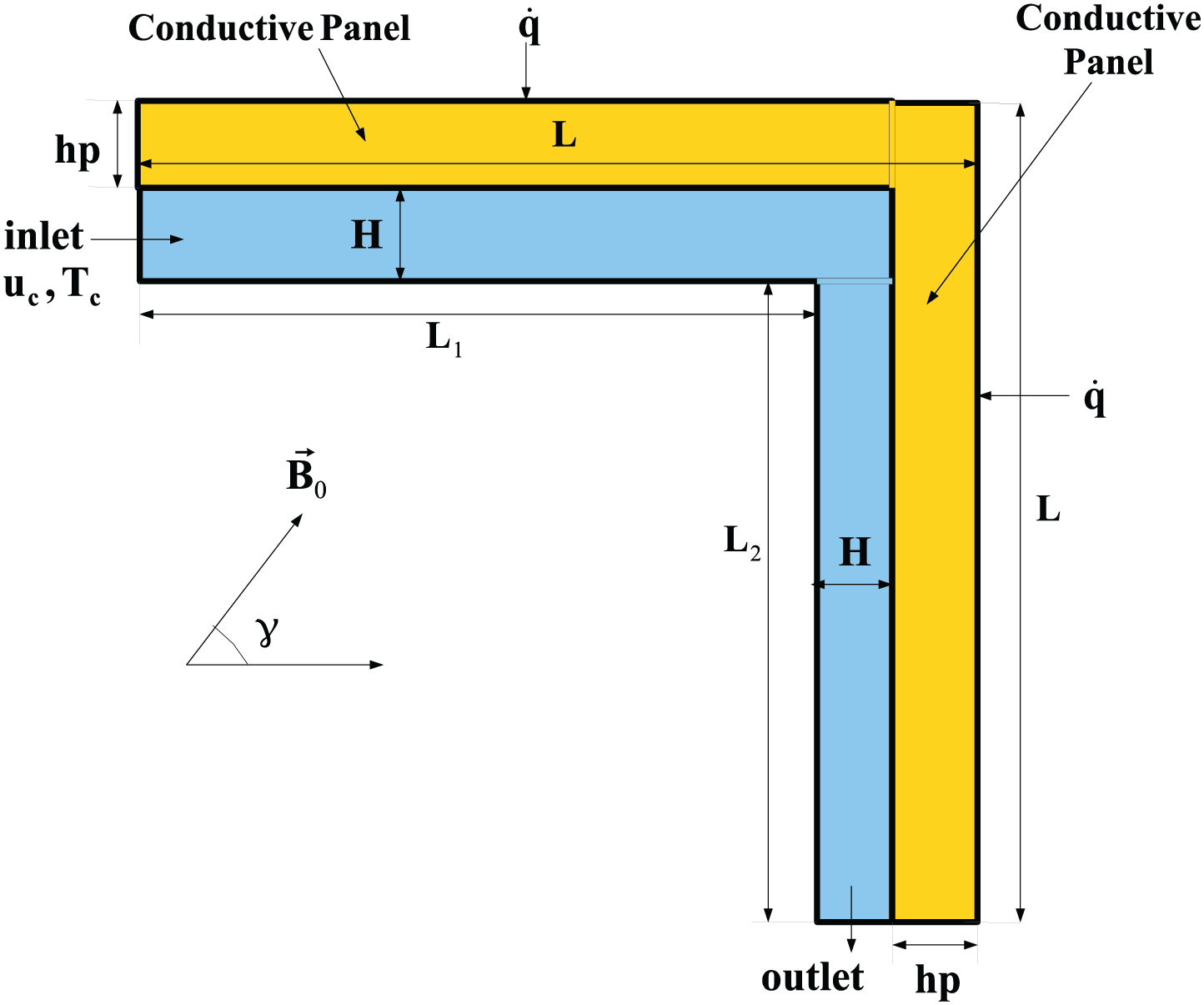
Figure 1: L-shaped cooling channel for double conductive panel system under inclined MGF effects
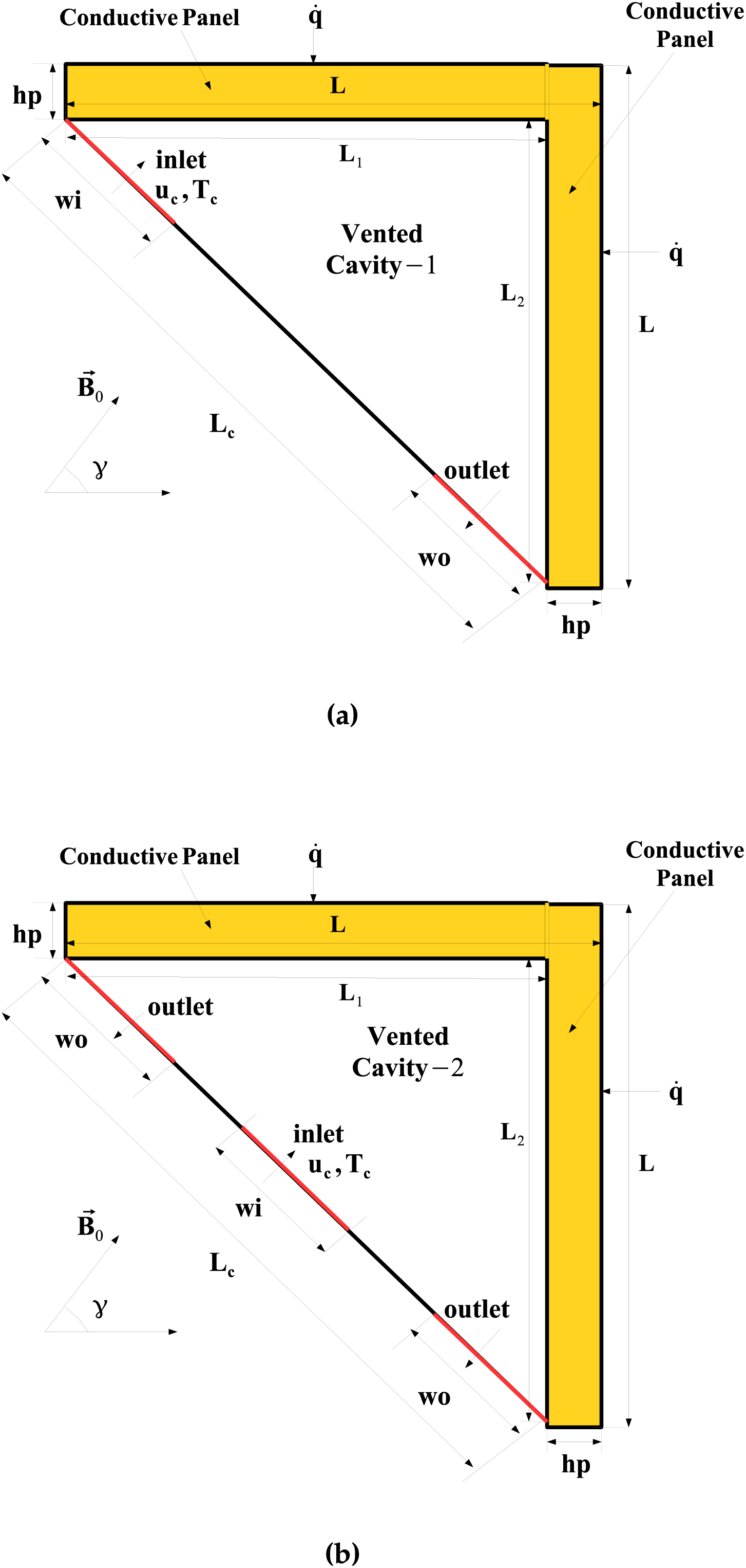
Figure 2: VC-1 system (one inlet, one outlet) (a) and VC-2 system (one inlet, two outlets) (b) for double conductive panel systems under inclined MGF effects
Following equations are considered for the cooling channel and L-shaped cooling channel [54,55]:
where the MGF strength and its inclination angle with respect to the horizontal are denoted by B and
The Reynolds number (Re), Hartmann number (Ha), Prandtl number (Pr), and conductivity ratio (KR), which are provided as follows, are the pertinent transport parameters of relevance:
where
• For the inlet of the channel and VC systems:
• At the exit of the cooling systems:
• For the cooling system-panel interface:
• At the walls of the cooling systems:
• At the panel upper surfaces:
The value of heat flux is
As the cooling fluid, NP having three NP compositions is used. NPs include platelet graphene, cylindrical MWCNT, and spherical aluminum oxide. The total NP solid volume fraction is given by
Definitions of
where
The NP solid volume percent ranges from 0 to 0.03.
The PV panel’s efficiency is directly proportional to its average surface temperature,
where the cell temperature is indicated by
where
where
GWR-FEM is used as the solution method. Numerous resources exist that cover the fundamentals and modeling concepts of FEM for convective HT [59,60]. Numerous research have demonstrated successful applications of FEM for convective HT with MG effects. Lagrange FEMs of varying orders are used to approximate field variables as in the following:
where the shape functions are described by
The SUPG (Streamline-Upwind Petrov-Galerkin) approach is utilized for treatment of numerical instability. In the fluid flow and HT modules, BICGStab (BiConjugate Gradient Stabilized) is taken into consideration. The convergence criterion is established at 10−7.
Grid independence tests are carried out for VC-systems and L-shaped cooling channel coupled with double conductive panels. Fig. 3a shows the element number for different grid scenarios considering VC-1 and L-shaped channel. Fig. 3b presents the average surface temperature of horizontal panel considering different grid cases. Grid system G4 is used for cooling channel VC-1 system. The number of element for VC-1 is 123,444 while for L-shaped channel, it is 123,333. Grid distribution of cooling systems are presented in Fig. 4 where refinement is made toward the interface between the panel and cooling channel and near the walls.
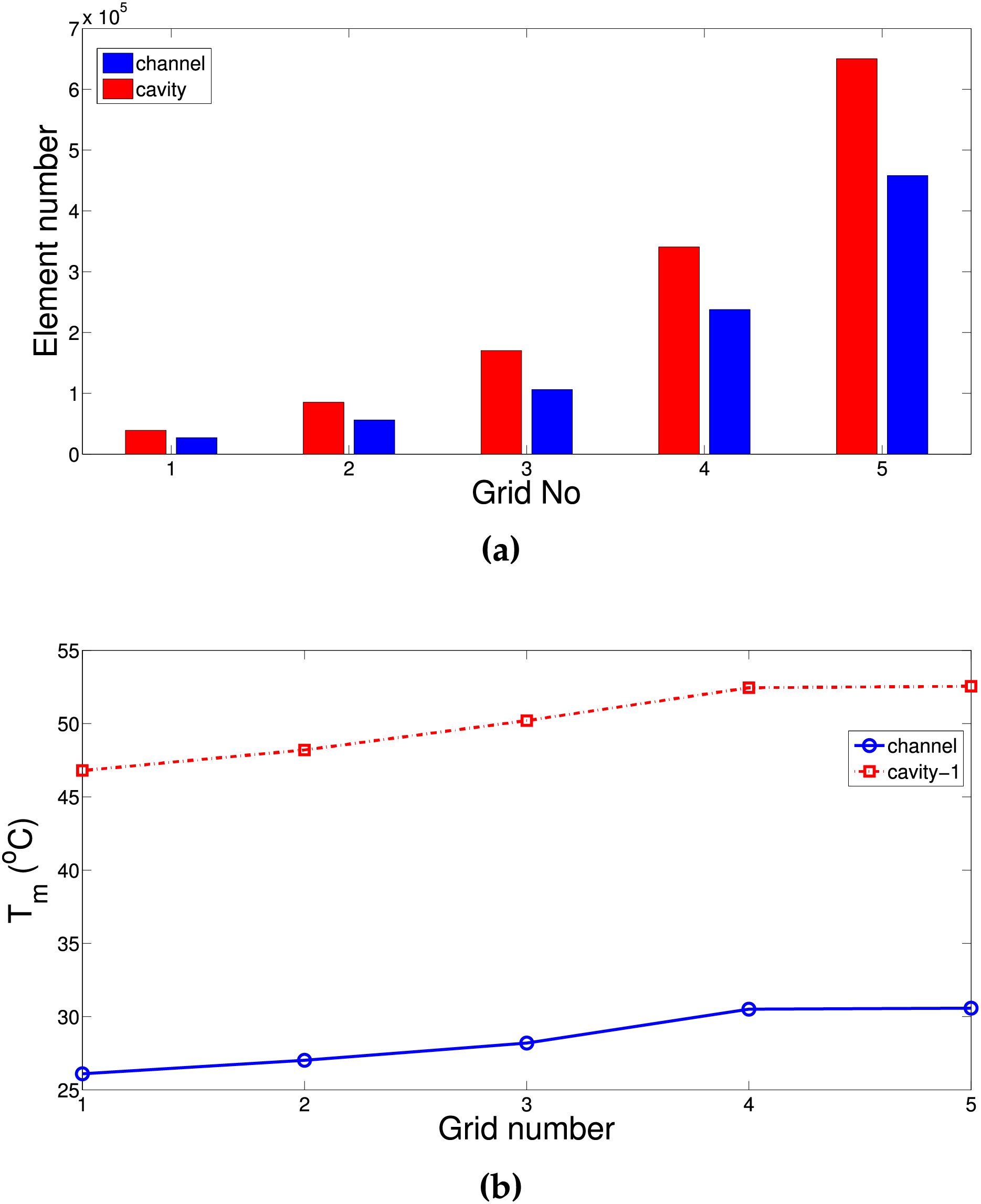
Figure 3: Element number for different gird cases with channel and cavity cooling systems (a) and grid independence test results for average temperature (b)
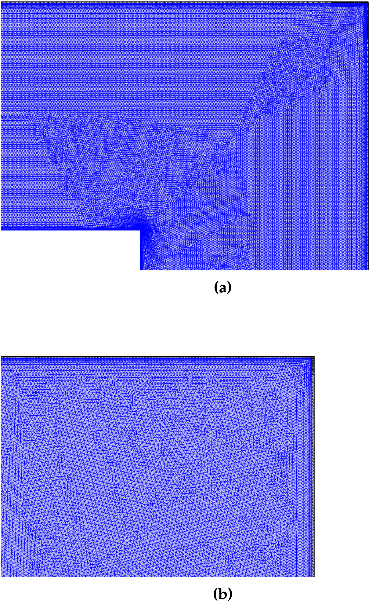
Figure 4: Grid distribution of reference case for channel (a) and cavity cooling system (b)
Code validation is performed by using different available relevant studies in the literature. In the first work, mixed convection in a VC system is examined by using the reference study in [61]. In the mentioned work, cavity had discrete heating elements on the vertical wall while experimental study was performed by utilizing Mach-Zehnder interferometry method. Experimental analysis was conducted for varying Re and heat source positions. Comparison of isotherms at heat source location of Yc = 0.5 at Re = 1600 is presented in Fig. 5a. In Fig. 5b, average Nu comparisons at two different Ra numbers are given. The highest deviation is found to be 4.61% between the results. In another validation, effects of MGF on the convective HT in a differentially heated cavity is taken into consideration while results from study in [62] are utilized. The aim is to show the impacts of using MGF on the convection and if the current code is capable of capturing MGF effects during convection in a cavity. Comparison of streamlines at Ha = 30 utilizing the current code and those found in the reference study of [62] are presented in Fig. 6a,b. Fig. 6c shows the average Nu vs. Ra at Ha = 30. As long as the highest variation stays below 3%, the general agreement between the results is good.
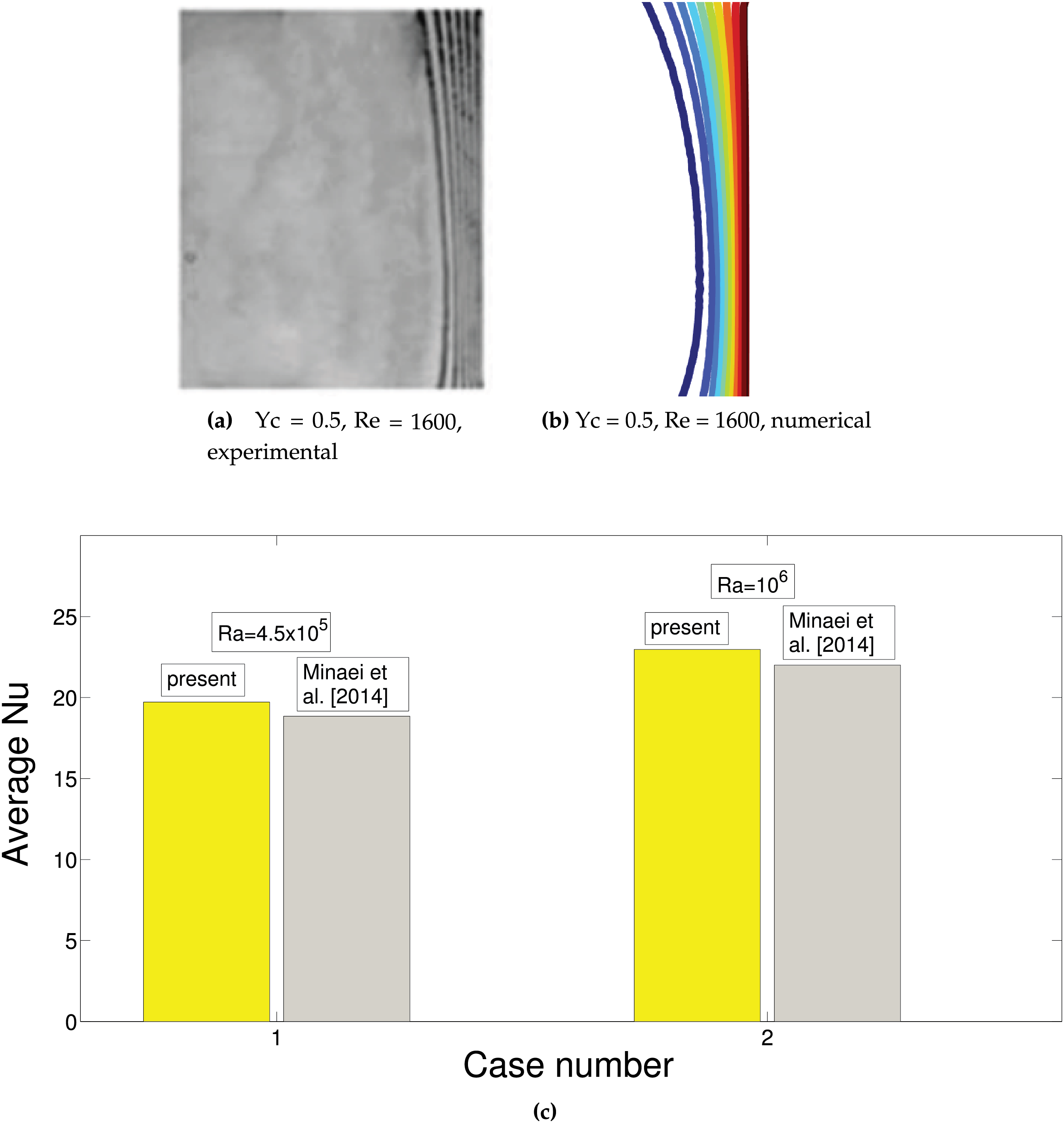
Figure 5: Validation 1: Comparison of isotherms from experimental work in [61] and obtained by using the present code at heat source location of Yc = 0.5 (a, b) and average Nu comparisons at two different Ra (c) for flow in VC system

Figure 6: Validation 2: Comparison of streamlines for convection in a differentially heated cavity under MGF effects at Ha = 30 (a, b) and average Nu vs. Ra comparisons at Ha = 30 (c) by using the results available in [62]
Thermal management of double conductive panel system is considered during forced convection of ternary NF in cooling channel or VCs. A uniform external MG-F is imposed. The numerical analysis is conduced for various values of MG-F strength (Ha between 0 and 50), inclination of MG-F (
Fig. 7 shows the streamline variations with different MG-F strength for inclination of
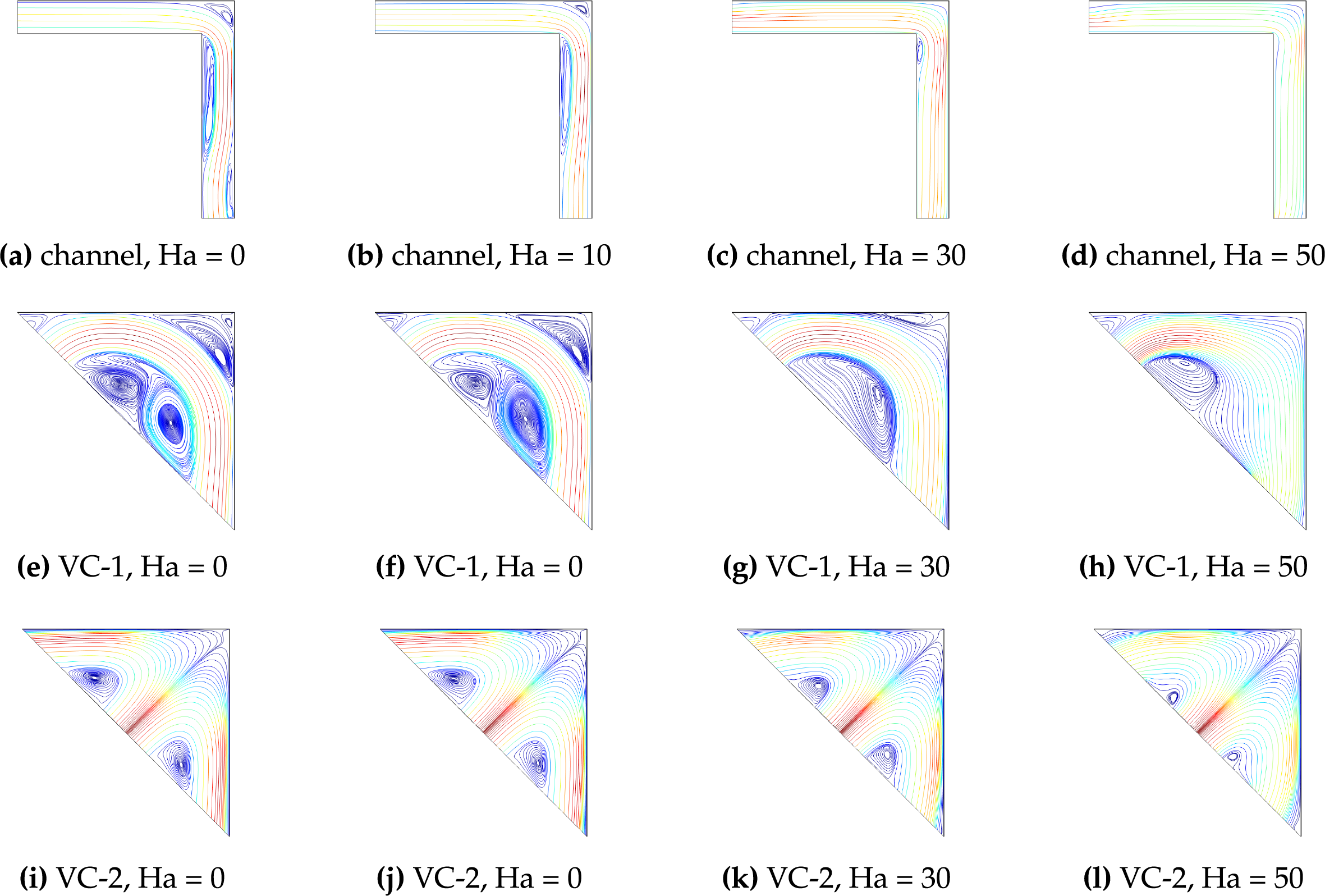
Figure 7: Effects of MGF strength (Ha number variation) on the distribution of streamlines in L-shaped channel (a–d) and VC systems (e–l) in non-uniform MGF case (A = 1,
Cooling performance is indicated by using the average Nu for each of the panels and their average surface temperatures. Fig. 8a,b shows the impacts of MG-F strength on the variation of average Nu for the horizontal and vertical panels considering uniform and non-uniform MGF effects for channel and VC cooling systems. When L-shaped channel is used, average Nu rises with higher MG-F strengths for both uniform and non-uniform cases. Vortex suppression near the upper corner and on the lower part of vertical channel is obtained which results in thermal transport improvement when L-shaped cooling channel is considered. Average Nu increments of 59.8% and 55.6% are obtained when MGF is imposed in the cooling channel at the highest strength considering uniform and non-uniform MGF. Due to the form of the non-uniform part of MGF, the overall impact of MGF is lower as compared to case of using uniform MGF. In VC systems, vortex formation is seen while imposing MGF controls the size and distribution of them in the VC cooling systems. When VC-1 cooling system is used, average Nu rises by about 14% by imposing MGF at the highest strength. When two exit vents are used, a corner vortex forms at the junction of the conductive panels; this vortex reduces as the MGF intensity increases. Consequently, the VC-1 cooling system’s thermal performance is slightly enhanced by larger Ha values. Imposing MGF causes a decline in cooling performance when taking into account VC-2 systems. This is explained by the fact that the main fluid stream with higher Ha has reduced fluid velocity and vortices are created away from the conductive panels. When uniform and non-uniform MGF effects are considered, average Nu reduction for VC-2 becomes 5.7% and 26.8%, respectively. For vertical panel, average Nu first decreases and then rises with higher Ha with channel cooling. When VC-1 cooling is used, average Nu reduces with higher Ha for vertical panel. This is attributed to the vortex reduction in the lower part of the cavity with higher Ha. As the vortices are formed for lower MGF strength case, they can be considered as obstacles while fluid stream velocity above it has higher velocity and thermal transport is higher for this panel. For VC-2, imposing non-uniform MGF leads to increase in average Nu. The discrepancies between the uniform and non-uniform MGF become more apparent for the vertical plate. By employing uniform-MGF at the highest strength the decrements of average Nu becomes 20.4% and 7.7% for VC-1 and VC-2 systems. When non-uniform MGF is imposed at Ha = 50, cooling performance improvement of 46% is obtained for VC-2 system. Average panel temperatures of both plates are considered as cooling performance index. For horizontal plate, optimum cooling effectiveness is attained by using channel cooling with MGF at the highest strength either uniform or non-uniform. The worst case for this plate is seen for VC-2 cooling system considering non-uniform MGF at the highest strength. When reference case of Ha = 0 is considered for the same cooling systems, temperature drops of horizontal panel becomes 11°C, 21.5°C and 3°C by using channel cooling, VC-1 and VC-2 systems for uniform MGF (Fig. 9). However, they become 9.5°C, 13.5°C and 12.5°C when non-uniform MGF is considered. For VC-2 system, imposing non-uniform MGF has the worst impact on the temperature drop. For vertical panel, in the presence of uniform MGF effects, using cooling channel, VC-1 and VC-2, results in temperature drops of 4°C, 10.8°C, 3.8°C while with non-uniform MGF effects, they become 0.5°C, 2.1°C and 9°C (Fig. 9).

Figure 8: Impacts of Ha number on the variation of average Nu for horizontal (a) and vertical (b) panels considering various cooling systems under uniform (U-MF) and non-uniform (N-MF) MGF effects (
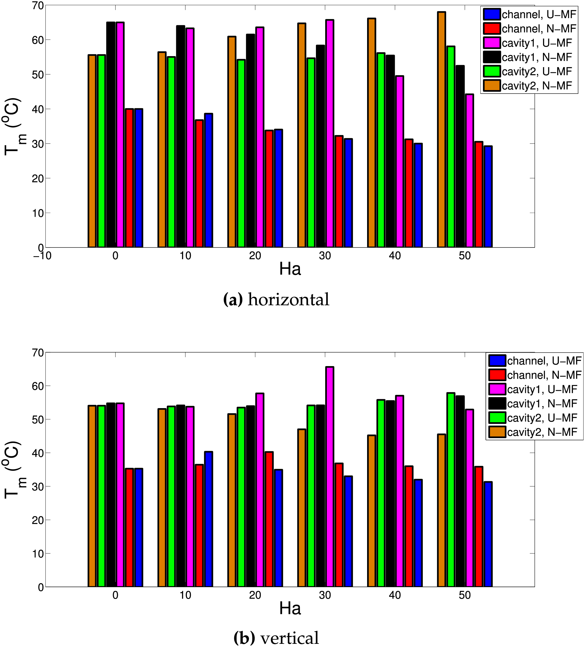
Figure 9: Effects of Ha number on the variation of average surface temperature of horizontal (a) and vertical (b) panels considering various cooling systems under uniform (U-MF) and non-uniform (N-MF) MGF effects (
Another influencing MGF parameter is the inclination angle. Fig. 10 shows the streamline distributions in various cooling systems. In channel cooling, horizontal MGF results in vortex formation on the corner junction and on the vertical channel. When inclination angle is increased, the corner vortex disappears while on the vertical channel its size increases. For VC-1 system, size of the upper corner vortex reduces with higher inclination. At
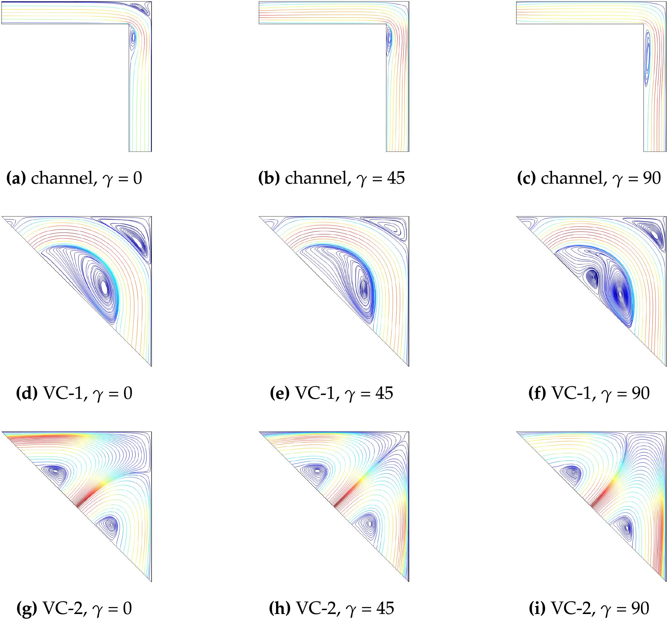
Figure 10: Impacts of MG inclination on the streamline distributions considering various L-shaped cooling channel (a–c), VC-1 system (d–f) and VC-2 cooling system (g–i) for non-uniform MGF cases (Ha = 25, A = 1,
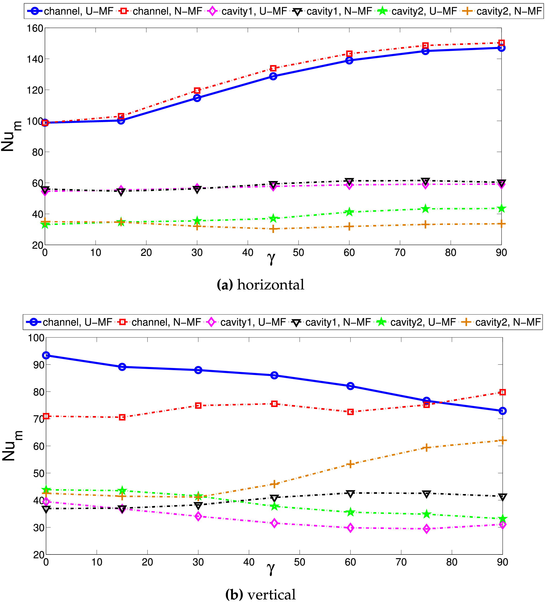
Figure 11: Average Nu variation of horizontal (a) and vertical (b) parts with different MG inclination considering various cooling channels for uniform (A = 0) and non-uniform (A = 1) MGF case (Ha = 25,
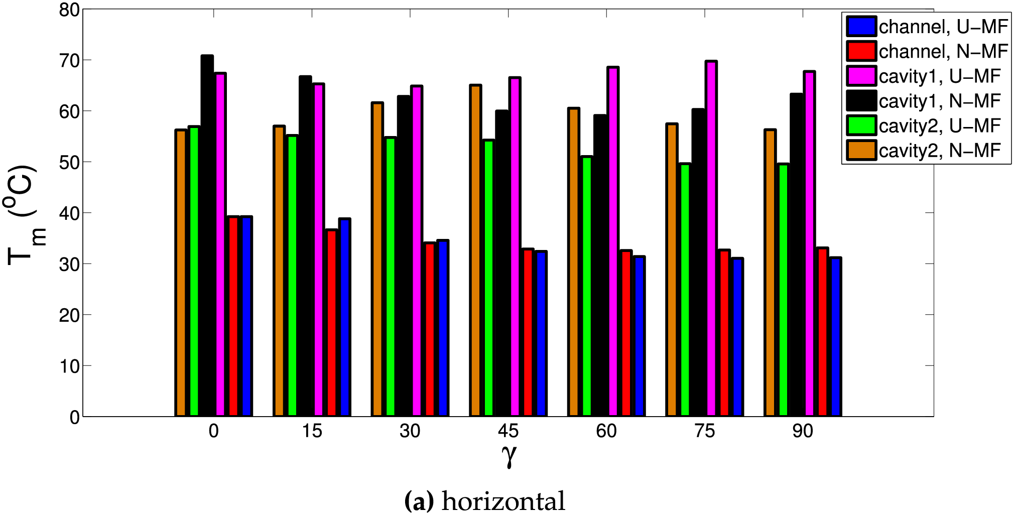
Figure 12: Impacts of MG inclination on the average surface temperatures of the horizontal (a) and vertical (b) panels considering various cooling channels for uniform (A = 0) and non-uniform (A = 1) MGF case (Ha = 25,
Ternary NF is used as the cooling medium. Thermal performance improvements by using hybrid NF in various convective HT systems have been shown in many studies. When hybrid ternary NPs are used in base fluid, favorable impacts on thermal conductivity and electrical conductivity improvements are obtained. Therefore, enhanced transport features with effective MGF effects are achieved in cooling systems under uniform and non-uniform MGF. Figs. 13 and 14 show temperature drops for horizontal and vertical panels with higher NP loading in the base fluid considering various cooling systems. There is a linear decreasing trend of average panel surface temperature with higher NP loading. For horizontal plate, temperature drops of 4°C, 10°C, and 12°C are obtained for NF at the highest loading. For vertical panel, they are obtained as 5°C, 7°C and 11°C. The potential of using ternary NF for VC-2 cooling system on the performance improvement is higher. This cooling system results in higher surface temperature of the panels while cooling system is least effective as compared to VC-1 and channel cooling system. Therefore, using NF results in more temperature reduction of the panel surface temperature for this system.
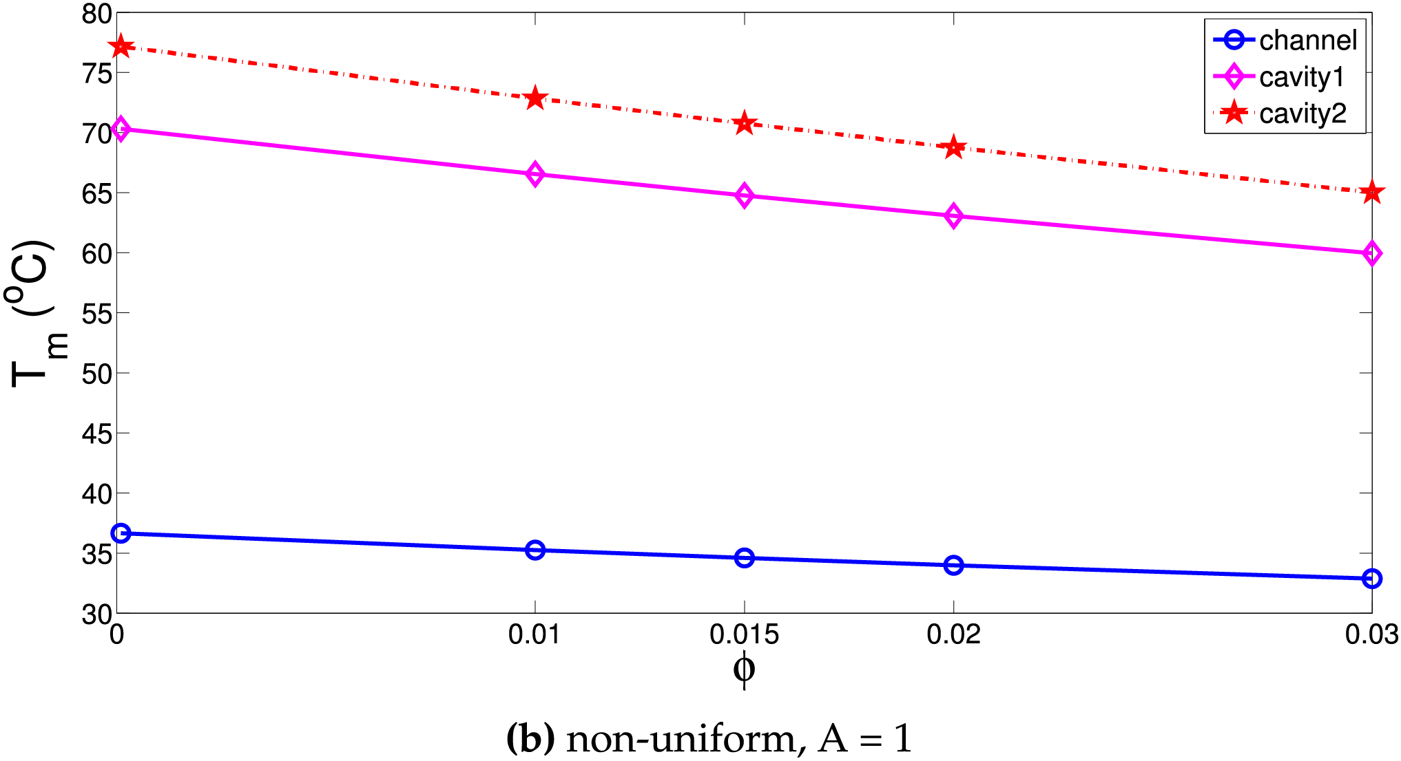
Figure 13: Effects of NP loading amount on the variation of average surface temperature of the horizontal panel with various cooling systems for uniform (a) and non-uniform (b) MGF cases (Ha = 25,
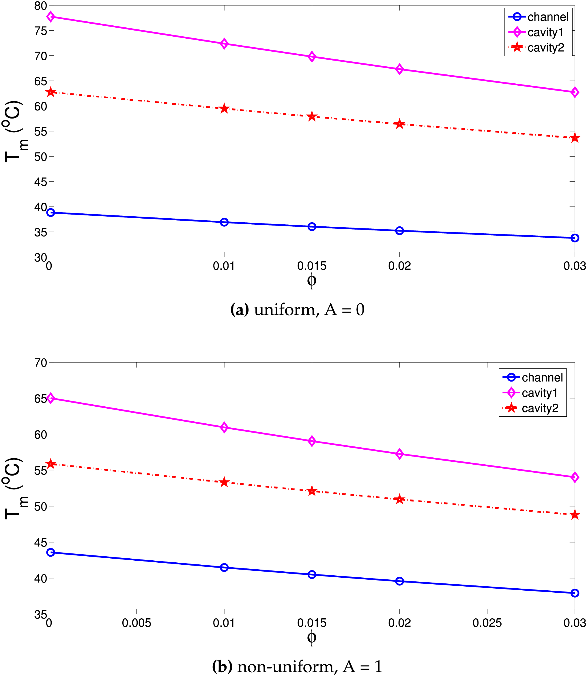
Figure 14: Effects of NP loading amount on the variation of average surface temperature of the vertical panel with various cooling systems for uniform (a) and non-uniform (b) MGF cases (Ha = 25,
Artificial neural network (ANN) is used for estimation of cooling performance of channel, VC-1 and VC-2 cooling systems. MGF parameters (amplitude and inclination) and NP loading impact on the average surface temperature of both panels are modeled by using feed-forward NN. The neuron model of ANN can be given as in the following [63]:
The input and
where
The ANN model structure with inputs, outputs and different layers is shown in Fig. 15. 10 neurons are utilized in the hidden layer. Different number of neurons in the hidden layer and different activation functions are tested. Higher neuron numbers greater than 15 lead to performance degradation while MSE values are higher when less than 8 neurons are used. With 10 neurons in the hidden layer, and hyperbolic tangent sigmoid function as the activation function, best results are achieved.

Figure 15: ANN architecture with inputs, outputs and different layers
Table 1 shows the MSE and

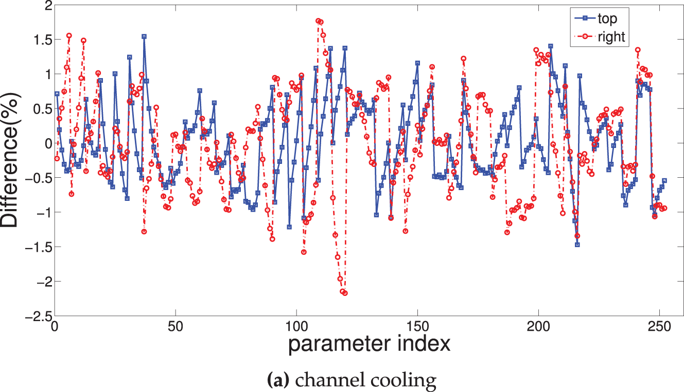
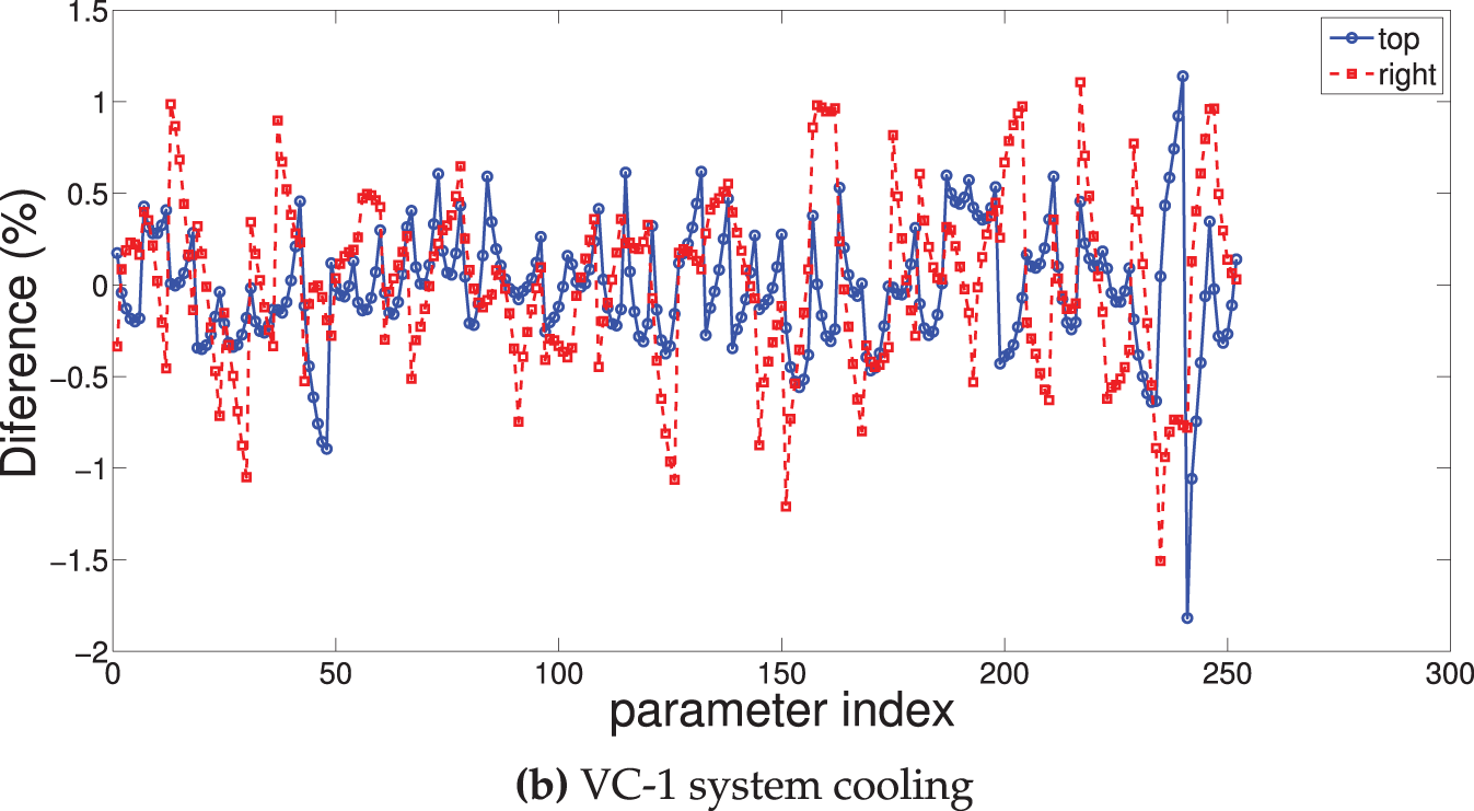
Figure 16: Error in the percentage for the estimation of average panel surface temperature considering channel cooling (a) and VC-1 system cooling (b)

Figure 17: Comparison of average panel surface temperatures (in °C) obtained from CFD and estimated with ANN for horizontal (a) and vertical (b) panels by using channel cooling

Figure 18: Comparison of average panel surface temperatures (in °C) obtained from CFD and estimated with ANN for vertical panels by using VC-1 (a) and VC-2 (b) cooling systems
Cooling systems are proposed for double conductive panel system which are positioned perpendicular to each other. L-shaped cooling channel and two VCs are used under combined impacts of using non-uniform inclined MGF and ternary NF. Following important outcomes are achieved as:
• Cooling performances for various channel are affected depending upon whether the imposed MGF is uniform or non-uniform.
• Using L-shaped channel cooling with MGF at the maximum strength-either uniform or non-uniform-will provide the best cooling performance for horizontal panel while worst cooling performance for this panel is obtained with VC-2 system with non-uniform MGF.
• Using L-channel, VC-1 and VC-2 systems for uniform MGF, temperature drops of the horizontal panel become 11°C, 21.5°C, and 3°C with varying MGF strength as compared to reference case of using Ha = 0. Yet, when non-uniform MGF is considered, they become 9.5°C, 13.5°C, and 12.5°C.
• Using cooling channel, VC-1 and VC-2 systems in the presence of uniform MGF effects leads in temperature decreases of 4°C, 10.8°C, and 3.8°C for vertical panels with varying strength of MGF as compared to reference case of Ha = 0. They are obtained as become 0.5°C, 2.1°C, and 9°C when non-uniform MGF effects are present.
• When varying MGF inclination in uniform case, horizontal panel surface temperature variations of 8°C, 2°C, and 7.3°C are obtained when using L-channel, VC-1 and VC-2 cooling system. They are 4°C, 11°C, and 7.5°C for vertical panel.
• At the highest loading of nanoparticle in the base fluid, for horizontal panel temperature drops of 4°C, 10°C, and 12°C are obtained for L-channel, VC-1 and VC-2 cooling system as compared to using only base fluid while they are 5°C, 7°C, and 11°C for the vertical panel.
• With 10 neurons in the hidden layer, ANN is used to estimate the cooling performance of the channel, VC-1, and VC-2 cooling systems. When taking into account different cooling methods for both panels, ANN captures the combined effects of applying non-uniform MGF and NF together on the cooling performance.
Present study can be extended to include exergy analysis, pressure drop effects, spatially varying and time dependent thermal boundary conditions. Different nanoparticle composition of ternary NF can be used and other hybrid NFs can be considered as the cooling medium. Turbulent flow regime and surface roughness effects of walls can be considered. The geometry of the cooling channel and VC (such as opening ratio of the inlet and outlet slots) can be considered in the ANN model for cooling system geometry optimization. There may be some challenges during the practical realization of the proposed cooling systems. But those systems are suitable for the cooling of double conducive panes which vertical to each other. Geometric modifications such as wavy surfaces for VCs can be considered. The elasticity of the walls, 3D effects and their impacts on the cooling performance can be studied as an extension of the current work. The present work shows that using uniform or non-uniform MGF effects may improve the cooling performance of horizontal or vertical panels. Further performance improvement of both panels are reached by adding NPs in base fluid and increasing its loading. In practical applications, experimental works for using nano-enhanced MGF can be adopted in the cooling part of multiple PV-units. When using NFs in practical system such as cooling unit of a PV module, cost of them, agglomeration kinetics and stability issues should be considered.
Acknowledgement: Not applicable.
Funding Statement: This research project was funded by the Deanship of Scientific Research and Libraries, Princess Nourah bint Abdulrahman University, through the Program of Research Project Funding after Publication, grant No. (RPFAP-88-1445).
Author Contributions: The authors confirm contribution to the paper as follows: Conceptualization, Fatih Selimefendigil, Kaouther Ghachem, Lioua Kolsi; methodology, Hind Albalawi, Fatih Selimefendigil, Kaouther Ghachem, Lioua Kolsi; software, Fatih Selimefendigil, Lioua Kolsi; validation, Fatih Selimefendigil, Kaouther Ghachem, Lioua Kolsi; formal analysis, Hind Albalawi, Fatih Selimefendigil, Kaouther Ghachem, Lioua Kolsi; investigation, Fatih Selimefendigil, Kaouther Ghachem, Lioua Kolsi; resources, Hind Albalawi, Kaouther Ghachem, Badr M. AlShammari; writing—original draft preparation, Fatih Selimefendigil, Kaouther Ghachem, Lioua Kolsi; writing—review and editing, Hind Albalawi, Fatih Selimefendigil, Kaouther Ghachem, Badr M. AlShammari, Lioua Kolsi; supervision, Hind Albalawi, Fatih Selimefendigil, Kaouther Ghachem, Badr M. AlShammari, Lioua Kolsi; funding acquisition, Hind Albalawi, Kaouther Ghachem. All authors reviewed the results and approved the final version of the manuscript.
Availability of Data and Materials: The data that support the findings of this study are available from the corresponding author upon reasonable request.
Ethics Approval: Not applicable.
Conflicts of Interest: The authors declare no conflicts of interest to report regarding the present study.
Abbreviations
| B0 | Magnetic field strength |
| A | Non-uniform amplitude |
| h | Heat transfer coefficient |
| H | Channel height |
| k | Thermal conductivity |
| KR | Conductivity ratio |
| ks | Panel thermal conductivity |
| L | Panel length |
| Nu | Nusselt number |
| p | Pressure |
| P | Perimeter |
| Pr | Prandtl number |
| Heat flux | |
| Re | Reynolds number |
| T | Temperature |
| x, y | Cartesian coordinates |
| Greek Characters | |
| Thermal diffusivity | |
| Temperature coefficient | |
| Solid volume fraction | |
| Kinematic viscosity | |
| Density | |
| Non-dimensional temperature | |
| Subscripts | |
| c | Cold |
| h | Hot |
| m | Average |
| nf | Nanofluid |
| p | Solid particle |
| pv | Photovoltaic |
| ref | Reference |
| w | Wall |
| Abbreviations | |
| ANN | Artificial neural network |
| CFD | Computational fluid dynamics |
| HT | Heat transfer |
| MGF | Magnetic field |
| MSE | Mean square error |
| NF | Nanofluid |
| PV | Photovoltaic |
| VC | Vented cavity |
References
1. Torbatinezhad A, Rahimi M, Ranjbar A, Gorzin M. Performance evaluation of PV cells in HCPV/T system by a jet impingement/mini-channel cooling scheme. Int J Heat Mass Transf. 2021;178(14):121610. doi:10.1016/j.ijheatmasstransfer.2021.121610. [Google Scholar] [CrossRef]
2. Hasanuzzaman M, Malek A, Islam M, Pandey A, Rahim N. Global advancement of cooling technologies for PV systems: a review. Sol Energy. 2016;137(6):25–45. doi:10.1016/j.solener.2016.07.010. [Google Scholar] [CrossRef]
3. Selimefendigil F, Okulu D, Oztop HF. Three dimensional numerical study of PV module cooling by using thermoelectric effects and nano-enhanced confined multiple slot jet impingement. Int J Heat Mass Transf. 2024;221:125093. doi:10.1016/j.ijheatmasstransfer.2023.125093. [Google Scholar] [CrossRef]
4. Waqas A, Ji J. Thermal management of conventional PV panel using PCM with movable shutters—a numerical study. Sol Ene. 2017;158:797–807. doi:10.1016/j.solener.2017.10.050. [Google Scholar] [CrossRef]
5. Wu SY, Zhang QL, Xiao L, Guo FH. A heat pipe photovoltaic/thermal (PV/T) hybrid system and its performance evaluation. Energy Build. 2011;43(12):3558–67. doi:10.1016/j.enbuild.2011.09.017. [Google Scholar] [CrossRef]
6. Tyagi PK, Kumar R. Performance enhancement of nanofluid-based photovoltaic/thermal system with a novel finned multi-block container of phase change material in the summer season of northern India. J Energy Storage. 2024;90(12):111733. doi:10.1016/j.est.2024.111733. [Google Scholar] [CrossRef]
7. Togun H, Basem A, Kadhum AAH, Abed AM, Biswas N, Rashid FL, et al. Advancing photovoltaic thermal (PV/T) systems: innovative cooling technique, thermal management, and future prospects. Sol Energy. 2025;291(4):113402. doi:10.1016/j.solener.2025.113402. [Google Scholar] [CrossRef]
8. Sheikholeslami M, Farshad SA, Ebrahimpour Z, Said Z. Recent progress on flat plate solar collectors and photovoltaic systems in the presence of nanofluid: a review. J Clean Prod. 2021;293(4):126119. doi:10.1016/j.jclepro.2021.126119. [Google Scholar] [CrossRef]
9. Jamil F, Ali HM, Nasir MA, Karahan M, Janjua M, Naseer A, et al. Evaluation of photovoltaic panels using different nano phase change material and a concise comparison: an experimental study. Renew Energy. 2021;169:1265–79. doi:10.1016/j.renene.2021.01.089. [Google Scholar] [CrossRef]
10. Siecker J, Kusakana K, Numbi BP. A review of solar photovoltaic systems cooling technologies. Renew Sustain Ener Rev. 2017;79:192–203. doi:10.1016/j.rser.2017.05.053. [Google Scholar] [CrossRef]
11. Tyagi PK, Kumar R. Comprehensive performance assessment of photovoltaic/thermal system using MWCNT/water nanofluid and novel finned multi-block nano-enhanced phase change material-based thermal collector: energy, exergy, economic, and environmental (4E) perspectives. Energy. 2024;312(12):133575. doi:10.1016/j.energy.2024.133575. [Google Scholar] [CrossRef]
12. Alizadeh H, Ghasempour R, Shafii MB, Ahmadi MH, Yan WM, Nazari MA. Numerical simulation of PV cooling by using single turn pulsating heat pipe. Int J Heat Mass Trans. 2018;127:203–8. doi:10.1016/j.ijheatmasstransfer.2018.06.108. [Google Scholar] [CrossRef]
13. Selimefendigil F, Öztop HF. Comparative study on different cooling techniques for photovoltaic thermal management: hollow fins, wavy channel and insertion of porous object with hybrid nanofluids. Appl Therm Eng. 2023;228(8–9):120458. doi:10.1016/j.applthermaleng.2023.120458. [Google Scholar] [CrossRef]
14. Royne A, Dey CJ. Design of a jet impingement cooling device for densely packed PV cells under high concentration. Sol Energy. 2007;81(8):1014–24. doi:10.1016/j.solener.2006.11.015. [Google Scholar] [CrossRef]
15. Ali HM. Recent advancements in PV cooling and efficiency enhancement integrating phase change materials based systems-A comprehensive review. Sol Energy. 2020;197(5813):163–98. doi:10.1016/j.solener.2019.11.075. [Google Scholar] [CrossRef]
16. Hamzat AK, Sahin AZ, Omisanya MI, Alhems LM. Advances in PV and PVT cooling technologies: a review. Sustain Energy Technol Assess. 2021;47:101360. doi:10.1016/j.seta.2021.101360. [Google Scholar] [CrossRef]
17. Saeidi SM, Khodadadi JM. Forced convection in a square cavity with inlet and outlet ports. Int J Heat Mass Trans. 2006;49(11–12):1896–906. doi:10.1016/j.ijheatmasstransfer.2005.10.033. [Google Scholar] [CrossRef]
18. Velazquez A, Arias JR, Montanes JL. Pulsating flow and convective heat transfer in a cavity with inlet and outlet sections. Int J Heat Mass Trans. 2009;52(3–4):647–54. doi:10.1016/j.ijheatmasstransfer.2008.07.020. [Google Scholar] [CrossRef]
19. Hamzah H, Canpolat C, Jasim LM, Sahin B. Hydrothermal index and entropy generation of a heated cylinder placed between two oppositely rotating cylinders in a vented cavity. Int J Mech Sci. 2021;201:106465. doi:10.1016/j.ijmecsci.2021.106465. [Google Scholar] [CrossRef]
20. Ouri H, Selimefendigil F, Bouterra M, Omri M, Alshammari BM, Kolsi L. MHD hybrid nanofluid convection and phase change process in an L-shaped vented cavity equipped with an inner rotating cylinder and PCM-packed bed system. Alexandria Eng J. 2023;63:563–82. doi:10.1016/j.aej.2022.08.016. [Google Scholar] [CrossRef]
21. Bakthavatchalam B, Habib K, Saidur R, Saha BB, Irshad K. Comprehensive study on nanofluid and ionanofluid for heat transfer enhancement: a review on current and future perspective. J Mol Liq. 2020;305:112787. doi:10.1016/j.molliq.2020.112787. [Google Scholar] [CrossRef]
22. Kasaeian A, Daneshazarian R, Mahian O, Kolsi L, Chamkha AJ, Wongwises S, et al. Nanofluid flow and heat transfer in porous media: a review of the latest developments. Int J Heat Mass Trans. 2017;107(6):778–91. doi:10.1016/j.ijheatmasstransfer.2016.11.074. [Google Scholar] [CrossRef]
23. Esfe MH, Bahiraei M, Hajbarati H, Valadkhani M. A comprehensive review on convective heat transfer of nanofluids in porous media: energy-related and thermohydraulic characteristics. Appl Therm Eng. 2020;178(1):115487. doi:10.1016/j.applthermaleng.2020.115487. [Google Scholar] [CrossRef]
24. Yang L, Jiang W, Ji W, Mahian O, Bazri S, Sadri R, et al. A review of heating/cooling processes using nanomaterials suspended in refrigerants and lubricants. Int J Heat Mass Transf. 2020;153:119611. doi:10.1016/j.ijheatmasstransfer.2020.119611. [Google Scholar] [CrossRef]
25. Pordanjani AH, Aghakhani S, Afrand M, Mahmoudi B, Mahian O, Wongwises S. An updated review on application of nanofluids in heat exchangers for saving energy. Energy Convers Manag. 2019;198:111886. doi:10.1016/j.enconman.2019.111886. [Google Scholar] [CrossRef]
26. Arshad W, Ali HM. Graphene nanoplatelets nanofluids thermal and hydrodynamic performance on integral fin heat sink. Int J Heat Mass Trans. 2017;107(5):995–1001. doi:10.1016/j.ijheatmasstransfer.2016.10.127. [Google Scholar] [CrossRef]
27. Miroshnichenko IV, Sheremet MA, Oztop HF, Abu-Hamdeh N. Natural convection of alumina-water nanofluid in an open cavity having multiple porous layers. Int J Heat Mass Trans. 2018;125:648–57. doi:10.1016/j.ijheatmasstransfer.2018.04.108. [Google Scholar] [CrossRef]
28. Sheremet MA, Revnic C, Pop I. Free convection in a porous wavy cavity filled with a nanofluid using Buongiorno’s mathematical model with thermal dispersion effect. Appl Math Comput. 2017;299:1–15. doi:10.1016/j.amc.2016.11.032. [Google Scholar] [CrossRef]
29. Arroub I, Bahlaoui A, Raji A, Hasnaoui M, Naïmi M. Cooling enhancement by nanofluid mixed convection inside a horizontal vented cavity submitted to sinusoidal heating. Eng Comput. 2018;35(4):1747–73. doi:10.1108/ec-03-2017-0080. [Google Scholar] [CrossRef]
30. Benzema M, Benkahla YK, Boudiaf A, Ouyahia SE, El Ganaoui M. Magnetic field impact on nanofluid convective flow in a vented trapezoidal cavity using Buongiorno’s mathematical model. Eur Phys J Appl Phys. 2019;88(1):11101. doi:10.1051/epjap/2019190239. [Google Scholar] [CrossRef]
31. Selimefendigil F, Öztop HF. Effects of an inner stationary cylinder having an elastic rod-like extension on the mixed convection of CNT-water nanofluid in a three dimensional vented cavity. Int J Heat Mass Trans. 2019;137:650–68. doi:10.1016/j.ijheatmasstransfer.2019.03.093. [Google Scholar] [CrossRef]
32. Benzema M, Benkahla YK, Labsi N, Ouyahia SE, El Ganaoui M. Second law analysis of MHD mixed convection heat transfer in a vented irregular cavity filled with Ag-MgO/water hybrid nanofluid. J Therm Anal Calorim. 2019;137(3):1113–32. doi:10.1007/s10973-019-08017-x. [Google Scholar] [CrossRef]
33. Prakash J, Ansu AK, Tripathi D. Alterations in peristaltic pumping of Jeffery nanoliquids with electric and magnetic fields. Meccanica. 2018;53(15):3719–38. doi:10.1007/s11012-018-0910-7. [Google Scholar] [CrossRef]
34. Murzin D, Mapps DJ, Levada K, Belyaev V, Omelyanchik A, Panina L, et al. Ultrasensitive magnetic field sensors for biomedical applications. Sensors. 2020;20(6):1569. doi:10.3390/s20061569. [Google Scholar] [PubMed] [CrossRef]
35. Pandey A, Kumar A, Tripathi D, Sharma K. Membrane-driven flow and heat transfer of viscoelastic fluids: MHD and entropy generation analysis. Int J Num Meth Heat Fluid Flow. 2025;42(3):187. doi:10.1108/hff-11-2024-0898. [Google Scholar] [CrossRef]
36. Giwa S, Sharifpur M, Ahmadi M, Meyer J. A review of magnetic field influence on natural convection heat transfer performance of nanofluids in square cavities. J Therm Anal Calorim. 2021;145(5):2581–623. doi:10.1007/s10973-020-09832-3. [Google Scholar] [CrossRef]
37. Hussain M, Sheremet M. Convection analysis of the radiative nanofluid flow through porous media over a stretching surface with inclined magnetic field. Int Commun Heat Mass Transf. 2023;140(6):106559. doi:10.1016/j.icheatmasstransfer.2022.106559. [Google Scholar] [CrossRef]
38. Mandal DK, Mondal MK, Biswas N, Manna NK, Chamkha AJ. Partial magnetic field and segmental heating effects on hybrid nanofluidic convection in a tilted porous wavy cavity. J Magn Magn Mater. 2023;583(3):171035. doi:10.1016/j.jmmm.2023.171035. [Google Scholar] [CrossRef]
39. Prakash J, Tripathi D, Tiwari AK, Pandey AK. Melting heat transfer and irreversibility analysis in Darcy-Forchheimer flow of Casson fluid modulated by EMHD over cone and wedge surfaces. Therm Sci Eng Progress. 2024;52(5):102680. doi:10.1016/j.tsep.2024.102680. [Google Scholar] [CrossRef]
40. Islam T, Yavuz M, Parveen N, Fayz-Al-Asad M. Impact of non-uniform periodic magnetic field on unsteady natural convection flow of nanofluids in square enclosure. Frac Fraction. 2022;6(2):101. doi:10.3390/fractalfract6020101. [Google Scholar] [CrossRef]
41. Ahmed SE, Hussein AK, Mansour M, Afrand M, Morsy Z, Kolsi L. Effect of magnetic field on the mixed convection in double lid-driven porous cavities filled with micropolar nanofluids. Num Meth Part Differ Eq. 2022;38(4):1090–111. doi:10.1002/num.22820. [Google Scholar] [CrossRef]
42. Izadi M, Hajjar A, Alshehri HM, Sheremet M, Galal AM. Charging process of a partially heated trapezoidal thermal energy storage filled by nano-enhanced PCM using controlable uniform magnetic field. Int Commun Heat Mass Transf. 2022;138(3):106349. doi:10.1016/j.icheatmasstransfer.2022.106349. [Google Scholar] [CrossRef]
43. Kherroubi S, Ragui K, Bensaci A, Labsi N, Boutra A, Benkahla YK. Effect of the second outlet location and the applied magnetic field within a ventilated cubic cavity crossed by a nanofluid on mixed convection mode: best configurations. J Therm Analy Calorim. 2020;139(3):2243–64. doi:10.1007/s10973-019-08638-2. [Google Scholar] [CrossRef]
44. Kasaeipoor A, Ghasemi B, Aminossadati S. Convection of Cu-water nanofluid in a vented T-shaped cavity in the presence of magnetic field. Int J Therm Sci. 2015;94(5):50–60. doi:10.1016/j.ijthermalsci.2015.02.014. [Google Scholar] [CrossRef]
45. Selimefendigil F, Öztop HF. Coupled effects of corrugation and rotation on the phase transition and thermal process in a vented cavity under MHD convection. J Energy Storage. 2024;77(1):109925. doi:10.1016/j.est.2023.109925. [Google Scholar] [CrossRef]
46. Geridönmez BP, Öztop HF. Effects of partial magnetic field in a vented square cavity with aiding and opposing of MWCNT-water nanofluid flows. Eng Anal Bound Elem. 2021;133(7):84–94. doi:10.1016/j.enganabound.2021.08.024. [Google Scholar] [CrossRef]
47. Gürdal M, Arslan K, Gedik E, Minea AA. Effects of using nanofluid, applying a magnetic field, and placing turbulators in channels on the convective heat transfer: a comprehensive review. Renew Sustain Energ Rev. 2022;162:112453. doi:10.1016/j.rser.2022.112453. [Google Scholar] [CrossRef]
48. Adun H, Kavaz D, Dagbasi M. Review of ternary hybrid nanofluid: synthesis, stability, thermophysical properties, heat transfer applications, and environmental effects. J Clean Prod. 2021;328:129525. doi:10.1016/j.jclepro.2021.129525. [Google Scholar] [CrossRef]
49. Abbas F, Ali HM, Shah TR, Babar H, Janjua MM, Sajjad U, et al. Nanofluid: potential evaluation in automotive radiator. J Mol Liq. 2020;297:112014. doi:10.1016/j.molliq.2019.112014. [Google Scholar] [CrossRef]
50. Adil A, Baig T, Manzoor S, Ali HM. Performance investigation of normal channel facile heat sink using hybrid nanofluid: an experimental and numerical approach. J Therm Anal Calorim. 2024;149(9):4049–68. doi:10.1007/s10973-024-12972-5. [Google Scholar] [CrossRef]
51. Hafeez MB, Krawczuk M, Nisar KS, Jamshed W, Pasha AA. A finite element analysis of thermal energy inclination based on ternary hybrid nanoparticles influenced by induced magnetic field. Int Commun Heat Mass Transf. 2022;135(9–10):106074. doi:10.1016/j.icheatmasstransfer.2022.106074. [Google Scholar] [CrossRef]
52. Ahmed SE, Raizah Z, Arafa AA, Hussein SA. FEM treatments for MHD highly mixed convection flow within partially heated double-lid driven odd-shaped enclosures using ternary composition nanofluids. Int Commun Heat Mass Transf. 2023;145(2):106854. doi:10.1016/j.icheatmasstransfer.2023.106854. [Google Scholar] [CrossRef]
53. Selimefendigil F, Oztop HF. Computational study and optimization of an inclined U-channel cooling system for triple conductive panels under magnetic field. Case Stud Therm Eng. 2025;65(8):105532. doi:10.1016/j.csite.2024.105532. [Google Scholar] [CrossRef]
54. Mehrez Z, El Cafsi A, Belghith A, Le Quere P. MHD effects on heat transfer and entropy generation of nanofluid flow in an open cavity. J Magn Magn Mater. 2015;374:214–24. doi:10.1016/j.jmmm.2014.08.010. [Google Scholar] [CrossRef]
55. Elshehabey HM, Hady F, Ahmed SE, Mohamed R. Numerical investigation for natural convection of a nanofluid in an inclined L-shaped cavity in the presence of an inclined magnetic field. Int Commun Heat Mass Trans. 2014;57(5):228–38. doi:10.1016/j.icheatmasstransfer.2014.07.004. [Google Scholar] [CrossRef]
56. Sahoo RR. Thermo-hydraulic characteristics of radiator with various shape nanoparticle-based ternary hybrid nanofluid. Powder Technol. 2020;370(1):19–28. doi:10.1016/j.powtec.2020.05.013. [Google Scholar] [CrossRef]
57. Kashyap S, Sarkar J, Kumar A. Performance enhancement of regenerative evaporative cooler by surface alterations and using ternary hybrid nanofluids. Energy. 2021;225(2):120199. doi:10.1016/j.energy.2021.120199. [Google Scholar] [CrossRef]
58. Bayrak F, Oztop HF, Selimefendigil F. Experimental study for the application of different cooling techniques in photovoltaic (PV) panels. Energy Convers Manag. 2020;212:112789. doi:10.1016/j.enconman.2020.112789. [Google Scholar] [CrossRef]
59. Lewis RW, Nithiarasu P, Seetharamu KN. Fundamentals of the finite element method for heat and fluid flow. Hoboken, NJ, USA: John Wiley & Sons; 2004. [Google Scholar]
60. Reddy JN, Gartling DK. The finite element method in heat transfer and fluid dynamics. Boca Raton, FL, USA: CRC Press; 2010. [Google Scholar]
61. Minaei A, Ashjaee M, Goharkhah M. Experimental and numerical study of mixed and natural convection in an enclosure with a discrete heat source and ventilation ports. Heat Trans Eng. 2014;35(1):63–73. doi:10.1080/01457632.2013.810455. [Google Scholar] [CrossRef]
62. Ghasemi B, Aminossadati S, Raisi A. Magnetic field effect on natural convection in a nanofluid-filled square enclosure. Int J Therm Sci. 2011;50(9):1748–56. doi:10.1016/j.ijthermalsci.2011.04.010. [Google Scholar] [CrossRef]
63. Haykin S. Neural networks: a guided tour. Nonlin Biomed Signal Process. 2000;1:53–68. [Google Scholar]
64. Kalogirou SA. Applications of artificial neural-networks for energy systems. Appl Energy. 2000;67(1–2):17–35. doi:10.1016/s0306-2619(00)00005-2. [Google Scholar] [CrossRef]
65. Yu C, Manry MT, Li J, Narasimha PL. An efficient hidden layer training method for the multilayer perceptron. Neurocomputing. 2006;70(1–3):525–35. doi:10.1016/j.neucom.2005.11.008. [Google Scholar] [CrossRef]
Cite This Article
 Copyright © 2025 The Author(s). Published by Tech Science Press.
This work is licensed under a Creative Commons Attribution 4.0 International License , which permits unrestricted use, distribution, and reproduction in any medium, provided the original work is properly cited.
 Downloads
 Citation Tools