
 Submit a Paper
 Propose a Special lssue
 Open Access
ARTICLE

General Improvement of Image Interpolation-Based Data Hiding Methods Using Multiple-Based Number Conversion
Department of Computer and Communication Engineering, National Kaohsiung University of Science and Technology, Kaohsiung, 824005, Taiwan
* Corresponding Author: Da-Chun Wu. Email:
Computer Modeling in Engineering & Sciences 2025, 144(1), 535-580. https://doi.org/10.32604/cmes.2025.067239
Received 28 April 2025; Accepted 13 June 2025; Issue published 31 July 2025
 View Full Text
 Download PDF
Abstract
Data hiding methods involve embedding secret messages into cover objects to enable covert communication in a way that is difficult to detect. In data hiding methods based on image interpolation, the image size is reduced and then enlarged through interpolation, followed by the embedding of secret data into the newly generated pixels. A general improving approach for embedding secret messages is proposed. The approach may be regarded a general model for enhancing the data embedding capacity of various existing image interpolation-based data hiding methods. This enhancement is achieved by expanding the range of pixel values available for embedding secret messages, removing the limitations of many existing methods, where the range is restricted to powers of two to facilitate the direct embedding of bit-based messages. This improvement is accomplished through the application of multiple-based number conversion to the secret message data. The method converts the message bits into a multiple-based number and uses an algorithm to embed each digit of this number into an individual pixel, thereby enhancing the message embedding efficiency, as proved by a theorem derived in this study. The proposed improvement method has been tested through experiments on three well-known image interpolation-based data hiding methods. The results show that the proposed method can enhance the three data embedding rates by approximately 14%, 13%, and 10%, respectively, create stego-images with good quality, and resist RS steganalysis attacks. These experimental results indicate that the use of the multiple-based number conversion technique to improve the three interpolation-based methods for embedding secret messages increases the number of message bits embedded in the images. For many image interpolation-based data hiding methods, which use power-of-two pixel-value ranges for message embedding, other than the three tested ones, the proposed improvement method is also expected to be effective for enhancing their data embedding capabilities.Keywords
Data hiding [1–5] can be employed to embed secret messages into cover images in an imperceptible manner, thereby achieving the objective of covert communication through the resulting stego-images. Data hiding methods yield stego-images with three key characteristics of the hidden message: imperceptibility, high capacity, and security. Some examples of data hiding methods using images as secret carriers are least significant bit (LSB) substitution [6], difference expansion [7,8], histogram shifting [9,10], prediction-error expansion [11,12], pixel-value differencing (PVD) [13], and image interpolation [14,15].
The LSB substitution method proposed by Wang et al. [6] takes advantage of the human eye’s inability to perceive slight changes in pixel values by substituting the less significant bits of pixel values to hide data. The LSB substitution method can also be combined with other data hiding techniques to achieve high embedding capacities while preserving the qualities of stego-images. An example is Solak [16] who combined the LSB substitution method with enhanced modified signed digit (EMSD) algorithms. Tian [7] proposed a difference expansion method which expands the difference value between every two adjacent pixels’ values by shifting left the bits of the difference value and embeds a message bit into the shifted value. Ni et al. [9] proposed a histogram shifting method which makes slight adjustments of ±1 to the pixel values within the range of each pair of zero and peak points in the image histogram, and embeds message bits into those pixel values which are identical to the peak-point value. Thodi and Rodríguez [11] proposed a prediction-error expansion method that merges the expansion embedding technique with a predictor-based decorrelation technique, achieving a higher embedding capacity than the difference expansion method.
Wu and Tsai [13] proposed the first PVD-based data hiding method, which embeds secret messages by adjusting the differences between the values of each pixel pair in an image. The entire range [0, 255] of all possible absolute values of the pixel pairs’ grayscale differences is divided into multiple smaller quantization ranges. The width of each quantization range is a power of two to facilitate the embedding of the bit-based information, yielding high data embedding rates. This method utilizes the difference in visual perception between smooth and rough areas, and embed more bits of the secret message in pixel pairs with larger pixel-value differences.
As a generalization of Wu and Tsai [13], Wu and Shih [17] supported the use of non-power-of-two quantization range widths by applying a multiple-based number conversion mechanism [18] which transforms the message bits collectively into a large multiple-based number and embeds each digit of the number into a pixel pair to achieve higher message embedding rates, significantly enhancing the flexibility and generalization of the original PVD data hiding method [13].
Image interpolation techniques [19,20] are commonly used for adjusting image sizes. These techniques compute the values of newly generated pixels resulting from the interpolation process based on the original pixel values in the input image. Jung and Yoo [14] proposed a data hiding method based on one such technique, called neighbor mean interpolation (NMI). The method at first scales the input image down to 1/4 of its original size and then scales it up using the proposed NMI technique to form a cover image, calculating the newly generated pixel values during scaling up as the averages of the pixel values of the existing neighboring pixels. Secret messages are hidden in the newly generated pixel values in each 3 × 3 block with the number of bits embedded in each pixel value being determined by the difference between the value of a pre-selected reference pixel (which is the upper-left corner pixel in the block) and the newly generated pixel value.
A method proposed by Chang et al. [21], based on the work of Jung and Yoo [14], employs a technique termed enhanced neighbor mean interpolation (ENMI) to improve image quality. The reference pixel is selected in the same as done in Jung and Yoo [14]. Also, a histogram modification method is applied to increase the embedding capacity. Malik et al. [22] proposed an improved NMI technique by assigning larger weights to closer neighboring pixels when estimating each newly created pixel value during the image interpolation process. The technique increases the embedding capacity compared to [21] and delivers better image quality than both [14,21].
Lee and Huang [15] proposed a data hiding method based on a technique referred to as interpolation by neighboring pixels (INP). The technique selects the corner pixel with the maximum value within each 3 × 3 image block in the cover image as the reference pixel, and message bits are embedded in each newly generated pixel value according to the value of the difference value computed in the same way as done in the NMI-based data hiding method [14] described above, thereby improving the yielded message embedding capacity. Tang et al. [23] enhanced the INP technique proposed by Lee and Huang [15] by selecting the maximum of the absolute differences between the corner pixels’ values and the newly generated pixel values. This maximum value is then used as the aforementioned difference value to determine the number of message bits to embed into the newly generated pixel values. The resulting method improves both embedding capacity and image quality compared to [15].
Recently, Mohammad et al. [24] proposed a new adaptive interpolation-based data hiding technique to improve the NMI-based image interpolation-based data hiding method [14], using an interpolation technique that assigns weights to the pixel values of all the four corners of each 3 × 3 block when calculating the three newly generated pixels’ values. Also, to prevent overflows to occur while embedding the message bits, more sophisticated formulas are used to compute the aforementioned reference values that are used to determine the number of message bits to embed into the newly generated pixel values. Furthermore, the maximum number of bits to embed is limited by a preset value, which allows for adjusting the trade-off between the quality of the stego-image and the data hiding capacity. For convenience, the interpolation technique used by this method is referred to as new interpolation expansion and abbreviated as NIE.
In more recent years, interpolated-based data hiding methods have received increasing attention in the research community. Some studies have focused on refining various aspects of the embedding process in interpolation-based data hiding methods. For example, Hassan and Gutub [25] proposed the use of multiple interpolation techniques during the image scaling-up phase to achieve high embedding capacity while maintaining acceptable image quality. Lu et al. [26] introduced a so-called multiple center folding strategy for encoding secret messages, which effectively reduces the distortion incurred in the stego-image. To enhance embedding capacity or image quality, several studies have integrated interpolation-based data hiding techniques with other information hiding approaches. For instance, Mandal et al. [27] combined the difference expansion technique to improve embedding capacity, while Fan et al. [28] incorporated the prediction-error expansion technique to reduce image distortion.
The objective of this study is to propose a general method for improving image interpolation-based data hiding techniques. The proposed approach aims to enhance embedding capacity by removing the powers-of-two restriction on the range of pixel values available for secret message embedding. Furthermore, a multiple-based number conversion technique [17,18,29] is incorporated to embed the secret messages effectively. The method increases the number of message bits embedded in the newly generated pixels, thereby increasing the message embedding capacity with the quality of the result stego-image degraded very slightly. Specifically, the proposed method is applied to enhance various image interpolation-based data hiding methods mentioned above, namely the well-known NMI-, INP-, and NIE-based data hiding methods, proposed by Jung and Yoo [14], Lee and Huang [15], and Mohammad et al. [24], respectively, to demonstrate its effectiveness.
The remainder of this paper is organized as follows. In Section 2, the related techniques discussed in this study are introduced. In Section 3, the proposed method utilizing the multiple-based number conversion technique for enhancing the three aforementioned image interpolation-based data hiding methods (i.e., the NMI-, INP-, and NIE-based data hiding methods) is presented in detail. Experiments implementing the proposed method for improving the three methods just mentioned have been conducted, and a comprehensive analysis of the experimental results is presented in Section 4. Finally, the conclusions of this study, along with suggestions for future works, are presented in Section 5 of this paper.
2 A Review of Related Techniques
In this section, techniques relevant to the present study are reviewed in detail. Specifically, a thorough review of the NMI-based data hiding method based on image interpolation, as proposed by Jung and Yoo [14] as well as an in-depth presentation of the multiple-based number conversion technique [18] used to improve the effectiveness of message embedding in image interpolation-based data hiding methods are included. In addition, the INP-based data hiding method proposed by Lee and Huang [15] and the NIE-based data hiding method proposed by Mohammad et al. [24] are presented in Appendices A and B, respectively, to shorten the main text and enhance the readability of this article.
2.1 A Review of the NMI-Based Data Hiding Method
The NMI-based data hiding method proposed by Jung and Yoo [14] was the first to perform message embedding based on the use of image interpolation results. The concept of typical image interpolation-based message embedding can be observed in the operations of the NMI-based data hiding method, which can be described from three aspects: image interpolation, message embedding, and message extraction.
2.1.1 The Image Interpolation Process
In general, a data hiding technique based on image interpolation first scales down the input image I of size W × H to create the original image Io, as referred to in [14], with both its width and height being halved, as shown in Fig. 1. Subsequently, the original image Io is scaled up to double its dimensions using an interpolation technique that is specifically designed for each distinct data hiding method. This scaled-up image Ic serves as the cover image, within which message data are embedded to yield a stego-image, as shown in Fig. 1.
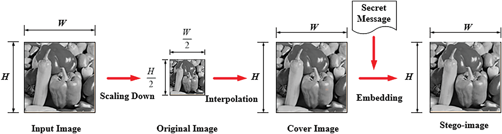
Figure 1: Illustration of the secret message embedding process of an image interpolation-based data hiding method
More specifically, during the image scaling-up process via interpolation, at first, the pixels of the original image Io are used to create overlapping 2 × 2 blocks in such a way that the column pixels in each block overlap with those of horizontally-neighboring blocks, and the row pixels overlap with those of vertically-neighboring blocks. For example, as shown by Fig. 2a, for a given 2 × 2 block B (drawn with red line segments as its boundary), its right column’s two pixels overlap with the left column’s two pixels of the horizontally adjacent right-side 2 × 2 block Bhr (drawn with green line segments as its boundary). That is, it can be said simply that Bhr is the overlapping horizontally-adjacent right-side block of B. Similarly, B has an overlapping vertically-adjacent bottom-side 2 × 2 block Bvb (drawn with green line segments as its boundary as shown in Fig. 2b), which has two pixels shared with B. Therefore, B has the two adjacent blocks Bhr and Bvb, as shown in Fig. 2c.
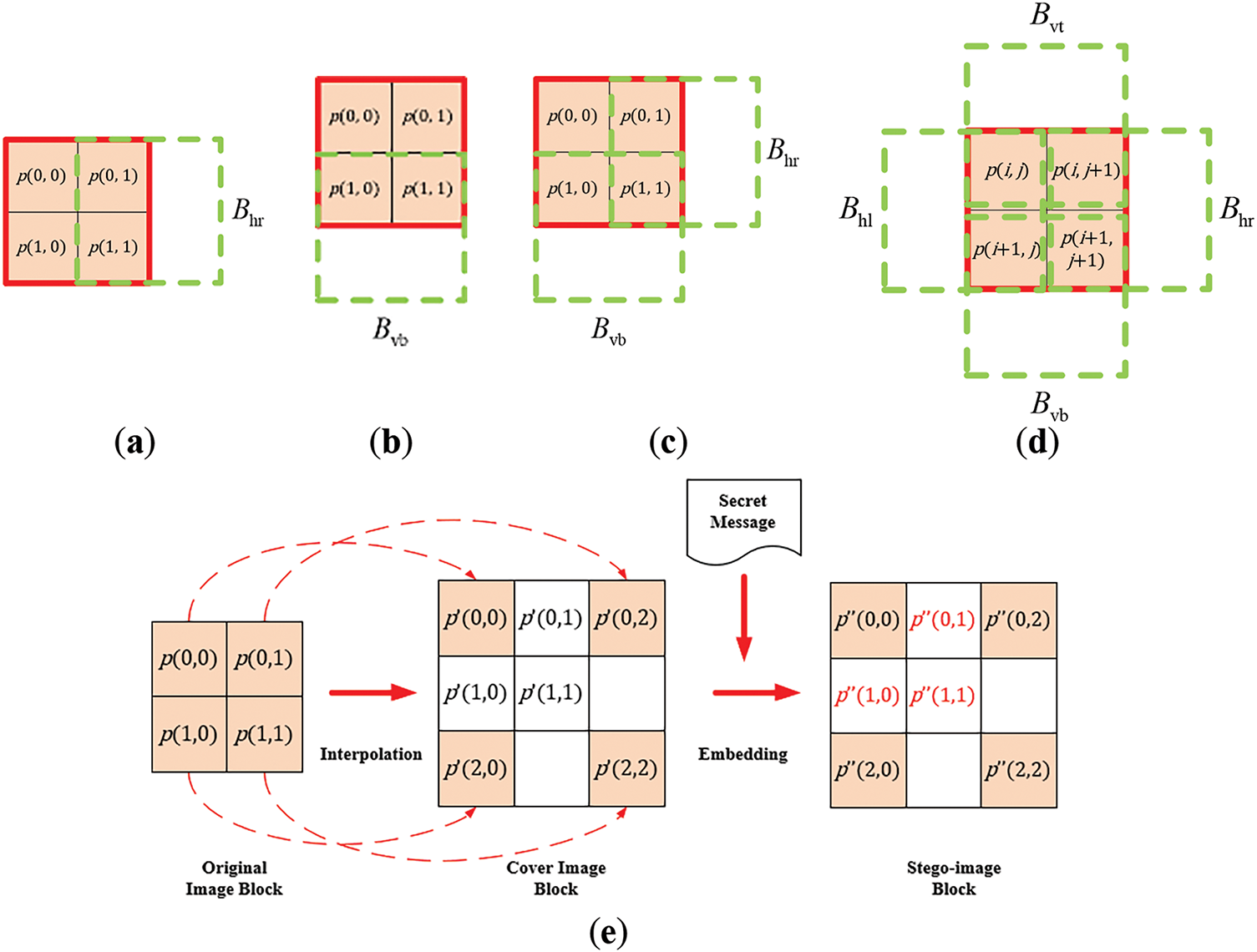
Figure 2: Illustration of a typical image interpolation-based data hiding method. (a–d) examples of overlapping 2 × 2 blocks obtained from the input image. (e) The steps of the interpolation and data embedding process
Note that in the previous discussion, B is assumed to be the block of the upper-left corner of an image. For the general case where B is a non-boundary 2 × 2 block instead of at the upper-left corner, then as shown in Fig. 2d, it has additionally both an overlapping horizontally-adjacent left-side 2 × 2 block Bhl and an overlapping vertically-adjacent top-side 2 × 2 block Bvt. In short, B has the four adjacent blocks Bhr, Bhl, Bvb, and Bvt.
Subsequently, the interpolation process is carried out for each 2 × 2 block B in a sequential manner, proceeding in a zig-zag fashion from left to right and from top to bottom, by enlarging the original image block B into a corresponding 3 × 3 overlapping block B′ in the cover image, as illustrated in Fig. 2e. The values of all the four pixels of B are copied directly to the four corners of B′ which are referred to as pivot pixels in [15]. The remaining pixels within B′ termed non-pivot pixels, are newly generated pixels whose values are calculated using a specific interpolation technique provided by each data hiding method.
Specifically, let the values of the pivot pixels at the four corners of B′ in the scaled-up cover image be denoted as p′(0, 0), p′(0, 2), p′(2, 0), and p′(2, 2), which correspond to the values of the four corner pixels of B of the original image, namely p(0, 0), p(0, 1), p(1, 0), and p(1, 1), respectively. That is
Also, the values of the three newly generated non-pivot pixels in the 3 × 3 cover image block B′, denoted as p′(0, 1), p′(1, 0), and p′(1, 1), are computed in terms of the values of the pivot pixels p′(0, 0), p′(0, 2), p′(2, 0), and p′(2, 2) using interpolation specified by each distinct hiding method as mentioned previously. Specifically, in the NMI-based data hiding method [14], the values of the non-pivot pixels are computed as
As shown in the center of Fig. 2e, there are still two blank pixels, one to the right and the other at the bottom, of the 3 × 3 block B′ with values that have not been processed yet. In fact, when the two 2 × 2 blocks, Bhr and Bvb, to the right and below the current block B, respectively, are processed, the values of these two blank pixels will be computed, as can be figured out according to the above-mentioned process for computing the values of the non-pivot pixels.
2.1.2 The Message Embedding Process
When a typical interpolation-based data hiding method is applied, the non-pivot pixels in each block B′ of the cover image are used to embed the input secret message. In this process, at first, the value of the pivot pixel p′(0, 0) in B′ is kept unchanged. That is, the pixel value p″(0, 0) of the resulting stego-image block is set to be the upper-left pixel value p′(0, 0) in the cover-image block B′:
Next, the numbers of bits that can be embedded in the three newly generated non-pivot pixels, respectively, are decided. First, a reference pixel P is identified for use in the message embedding process. The value of P is called the reference pixel value and denoted as R. For example, in the NMI-based method, P is chosen as the upper-left corner pixel in B′ with value p′(0, 0), i.e., R is set to be
After determining the reference pixel value R, three absolute difference values δi, where i = 1, 2, 3, are calculated. For example, in the NMI-based method, the calculations are listed as follows:
where p′(0, 1), p′(1, 0), and p′(1, 1) are the newly generated non-pivot pixel values described in Eq. (2) above.
Subsequently, the number of bits embeddable in each of the non-pivot pixels with values p′(0, 1), p′(1, 0), and p′(1, 1), denoted as ni (i = 1, 2, 3), are determined. For example, in the NMI-based method, they can be expressed as
where ⌊·⌋ denotes the floor function.
Finally, the message bit embedding is proceeded by taking ni bits (i = 1, 2, 3) from the secret message in sequence, converting it into a decimal value vi, and the resulting values v1, v2, and v3 are added to the non-pivot pixel values p′(0, 1), p′(1, 0), and p′(1, 1), respectively, resulting in the new pixel values p″(0, 1), p″(1, 0), and p″(1, 1) in the corresponding block in the stego-image. That is, the pixel values p″(0, 1), p″(1, 0), and p″(1, 1) are set respectively to be
After embedding all message bits into the blocks of the cover image, a stego-image containing the hidden message is generated, as illustrated in Fig. 2e as well.
2.1.3 The Message Extraction Process
During the message extraction process performed by a typical interpolation-based method, the pixel values of the original cover image are required. These values are directly calculated from the stego-image without the need to actually recover the cover image. Conceptually, this can be seen as recovering the cover image initially for use in the message extraction process, as illustrated in Fig. 3. The details are explained further below.
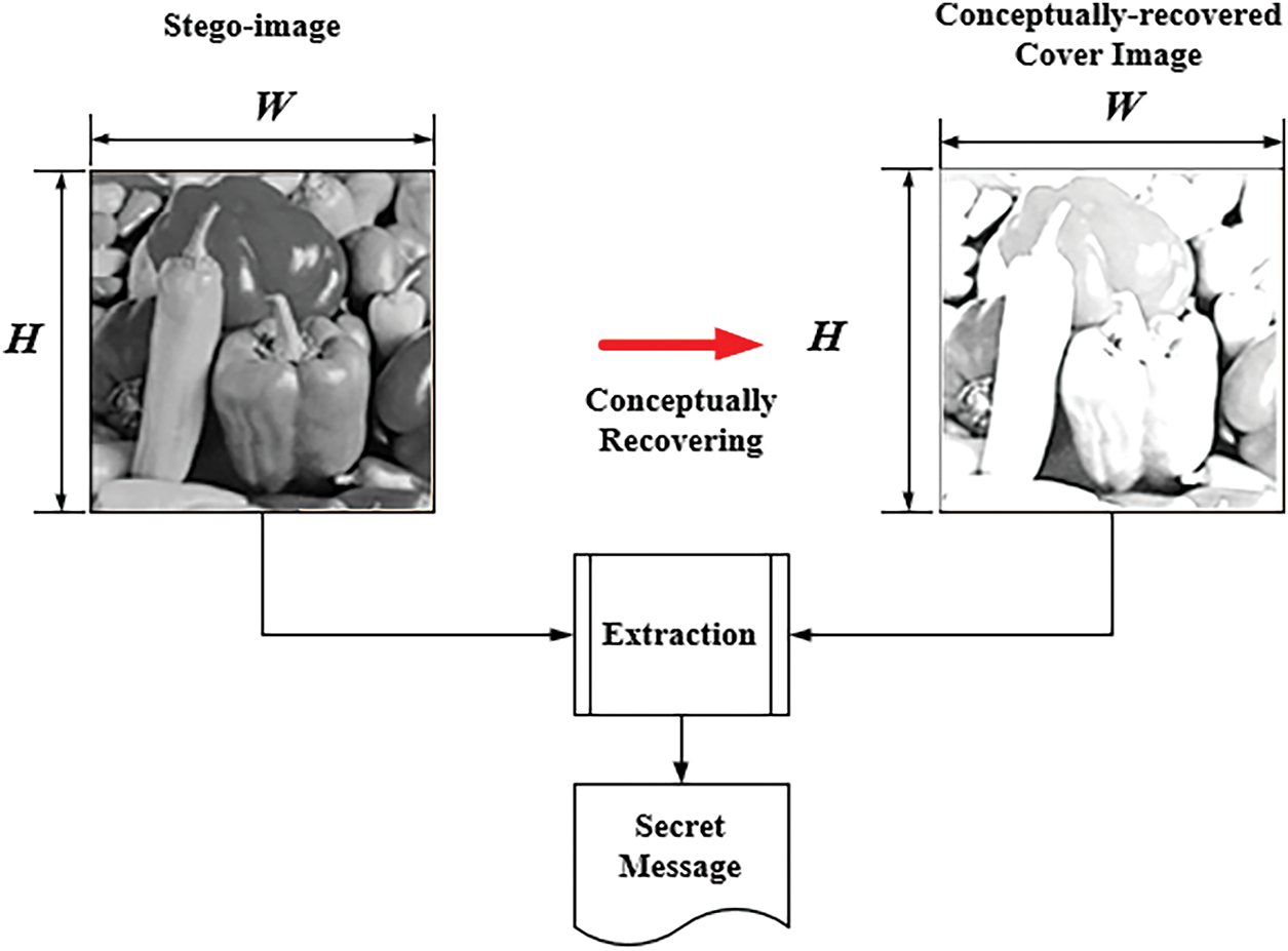
Figure 3: Illustration of the secret message extraction process of an image interpolation-based data hiding method
Initially, the values of the pivot pixels in the conceptually recovered cover image Ic are copied from those of the pivot pixels in the stego-image S, while the values of the non-pivot pixels in Ic are reconstructed by referencing the pivot pixels and using the same interpolation technique applied during the message embedding process. Specifically, in the NMI-based data hiding method [14], the technique described in Eq. (2) is applied and the pixel values p′(0, 1), p′(1, 0), and p′(1, 1) of Ic can be computed from the pixel values of S as
Subsequently, both S and the Ic are segmented into overlapping 3 × 3 blocks using the same approach as done in message embedding, as depicted in Fig. 4. The number ni of bits with i = 1, 2, 3, which were embedded in each of the three newly generated pixels in each block of the cover image can be retrieved separately according to the same calculation steps as done in the message embedding process.
Figure 4: Illustration of the data extraction process for blocks in typical image interpolation-based data hiding methods
Next, the pixel values p′(0, 1), p′(1, 0), and p′(1, 1) of each cover image block B′ are subtracted respectively from the corresponding pixel values p″(0, 1), p″(1, 0), and p″(1, 1) of the corresponding stego-image block B″ to obtain three pixel-value differences v1, v2, and v3:
Subsequently, each pixel-value difference vi (i = 1, 2, 3) is converted into a binary number N. If N has fewer than the required ni bits computed according to the Eqs. (3)–(5), it is padded with leading zeros.
By the way, the two blank pixels at the right and bottom sides of the 3 × 3 stego-image block B″ shown on the left of Fig. 4 are not treated at this stage, just like the case in the message embedding process. The secret messages embedded in these two pixels are extracted later in the next stage when processing the adjacent 3 × 3 blocks of B″ on the right and bottom sides.
2.2 Multiple-Based Number Conversion Technique
Wu and Tsai [18] proposed a new method of data hiding based on the concept of multiple-based number conversion. An n-digit multiple-based number is represented as
where each digit di in the number has a corresponding base bi > 1 for i = 0, 1, … , n − 1. The value of di falls within the range from 0 to bi − 1. Its decimal value may be computed by the following equation:
The operation of multiple-based number conversion has the following two properties which were reported in [18].
Property 1.
An integer I can be represented as a multiple-based number dn−1(bn−1)dn−2(bn−2) … d2(b2)d1(b1)d0(b0) through successive integer divisions of I by the bases b0, b1, . . . , bn−1, where each di is the remainder of the respective division.
Property 2.
If the selected bases bn−1, bn−2, … , b0 satisfy the equation
Based on the above properties, for example, if it is desired to convert the decimal number m0 = 56410 into a multiple-based number N with base values b0 = 9, b1 = 5, and b2 = 13, then N can be represented as d2(b2)d1(b1)d0(b0) where the values of d0, d1, and d2 can be computed step by step in the following way and as illustrated in Fig. 5.
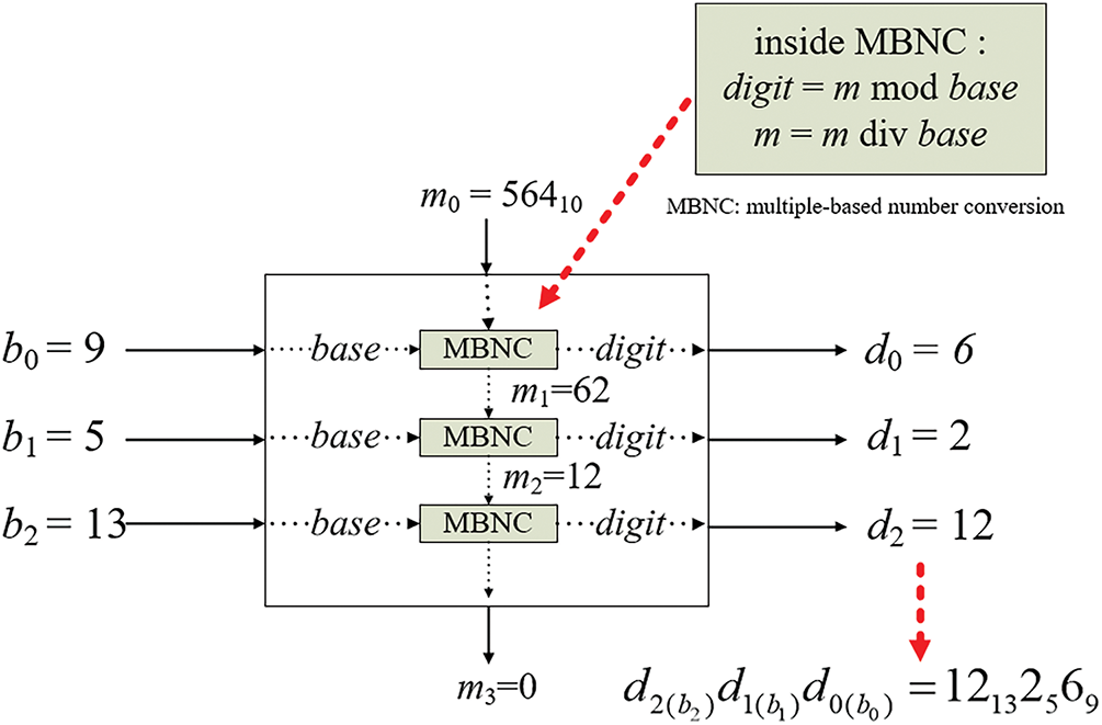
Figure 5: Illustration of applying the proposed multiple-based number conversion process to convert decimal number 56410 into a multiple-based number 12132569
(1) Perform the integer division of m0 = 564 by the base b0 = 9, resulting in a quotient of m1 = 62 and a remainder of 6. Therefore, d0 is taken to be the digit value 6 with base 9, i.e., d0(b0) = 69.
(2) Divide the quotient m1 = 62 by the second base b1 = 5, yielding a new quotient of m2 = 12 and a remainder of 2. Consequently, the digit value d1(b1) of the multiple-based number is 25.
(3) Divide the quotient m2 = 12 by the third base b2 = 13, resulting in a quotient of m3 = 0 and a remainder of 12 so that digit value d2(b2) of the multiple-based number is 1213.
(4) Combine the above intermediate results into a multiple-based number d2(b2)d1(b1)d0(b0) 12132569 as the final result.
In practice, to convert the multiple-based number dn−1(bn−1)dn−2(bn−2) … d2(b2)d1(b1)d0(b0) into its decimal equivalent, one can simply add the decimal values represented by each digit di(bi) for i = 0, 1, … , n − 1. Specifically, the value represented by the digit di(bi) is computed as the value of the coefficient di multiplied by
Accordingly, to convert a multiple-based number into its decimal equivalent m, first set the initial value m0 of m to be 0 and the initial value a0 of the multiplier a to be 1. Then, process di(bi) sequentially for i = 0, 1, … , n − 1 and add di × ai one by one to decimal equivalent m. That is, the accumulation of the decimal values represented by di(bi) can be expressed as
After summing up di(bi), the multiplier ai is then multiplied by bi, yielding the next multiplier needed for calculating di+1(bi+1), i.e., the next a can be expressed as
This process of computations using Eqs. (10) and (11) are repeated for each di(bi) in the multiple-based number until all the digit values have been summed up to obtain finally the desired decimal equivalent m.
For example, to convert the multiple-based number N = 12132569 to be a decimal number, first set the initial value m0 of m to be 0 and the initial value a0 of the multiplier a to be 1. Then, extract the rightmost digit of N, which is 69 and calculate the next values of m and a to be m1 = 6, a1 = 9, according to Eqs. (10) and (11), respectively. Next, extract the second digit of N, namely 25, and calculate the new values of m and a to be m2 = 6 + 2 × 9 = 24, a2 = 9 × 5 = 45. Finally, extract the third digit of N, which is 1213 and calculate the final value of m to be m3 = 24 + 12 × 45 = 564. At this point, the conversion of 12132569 is completed with the decimal value 56410 as the desired result.
3 Proposed General Improvement of Various Image Interpolation-Based Data Hiding Methods Using Multiple-Based Number Conversion
The proposed method, which is designed to generally improve various existing image interpolation-based data hiding techniques, including the processes of message embedding and extraction, is illustrated in Figs. 6 and 7, respectively. In other words, these two figures together represent an interpolation-based data-hiding system enhanced by the proposed method.
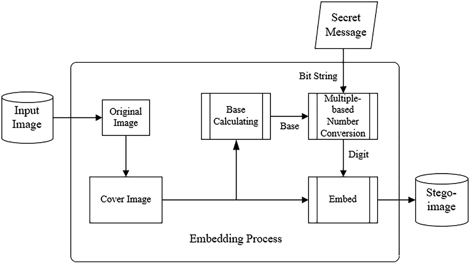
Figure 6: Illustration of the embedding process in an interpolation-based data-hiding system improved by the proposed method
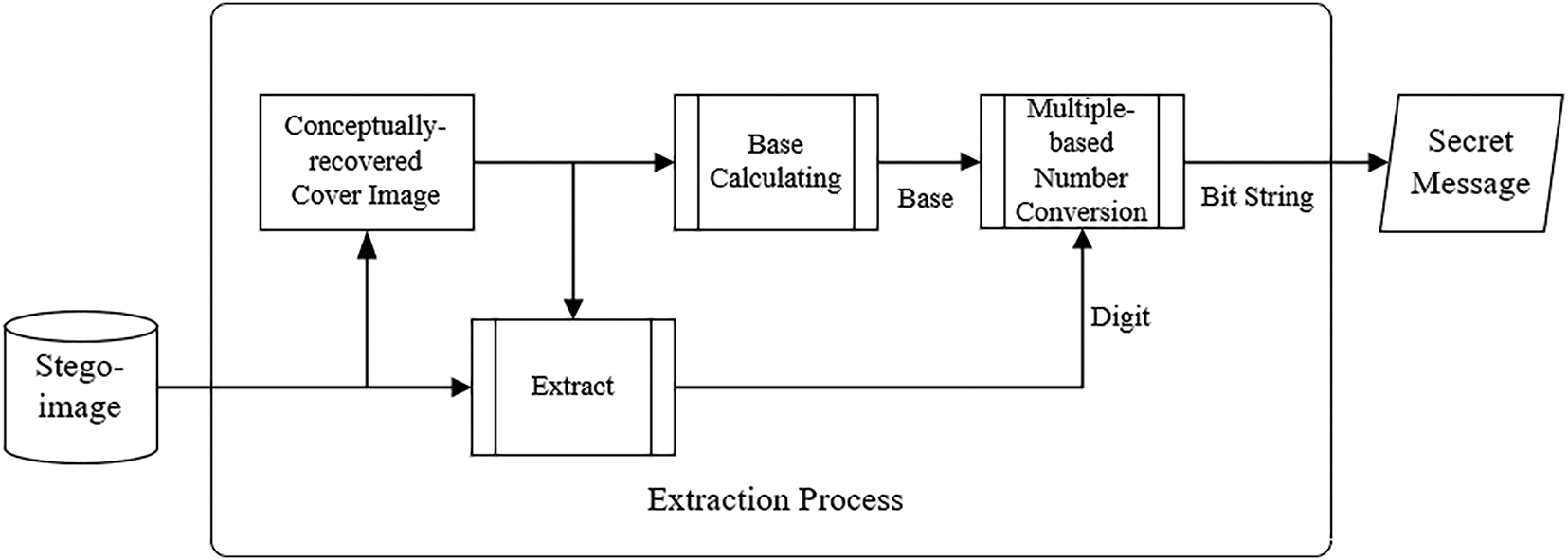
Figure 7: Illustration of the extraction process in an interpolation-based data-hiding system improved by the proposed method
In this section, the principle of generally improving the image interpolation-based data hiding method by use of the multiple-based number conversion technique as proposed in this study is presented at first. Then, a detailed description of how this improvement technique is applied in message embedding and extraction to enhance the effectiveness of the NMI-based data hiding method [14] is presented. The improvement technique has also been applied to the INP-based and NIE-based data hiding methods [15,24] in this study, and the comprehensive details are provided in Appendices C and D, again to maintain the conciseness and readability of the main text.
3.1 Use of Proposed Multiple-Based Number Conversion to Generally Enhance Data Hiding Capacity
The NMI-, INP-, and NIE-based data hiding methods [14,15,24] all use the created 3 × 3 overlapping blocks of the cover image to embed message data into the values of three newly generated non-pivot pixels, namely p′(0, 1), p′(1, 0), and p′(1, 1), within each image block, as shown in Fig. 2. These three methods compute the numbers of message bits that can be embedded into the newly generated pixels in different ways as described previously and summarized in the following.
(1) The NMI-based data hiding method [14] uses the absolute difference δ between the reference pixel value p′(0, 0) in each block and each of the three newly generated non-pivot pixels’ values p′(0, 1), p′(1, 0), and p′(1, 1) to compute the number of bits that can be embedded into the corresponding pixel value as ⌊log2δ⌋.
(2) The INP-based data hiding method [15] uses the maximum value R of the four corner pixels’ values, namely p′(0, 0), p′(0, 2), p′(2, 0), and p′(2, 2), in each block as the reference pixel value, finds the absolute difference δ between this reference pixel value and each of the three newly generated non-pivot pixels’ values p′(0, 1), p′(1, 0), p′(1, 1) to calculate the number of bits that can be embedded into the corresponding pixel value as ⌊log2δ⌋.
(3) The NIE-based data hiding method [24] defines p′(0, 0) as the reference pixel value R, calculates the smallest of the three values |R − p′|, 255 − p′, and 2U (where 1 ≤ U ≤ 8) for each newly generated pixel with value p′ as the pixel-value difference δ, and then computes the number of bits that can be embedded into p′ as ⌊log2δ⌋.
As a summary, the three aforementioned image interpolation-based data hiding methods [12,13,21] perform the following steps of operations for message-bit embedding in each non-pivot pixel in each created 3 × 3 block B of the cover image.
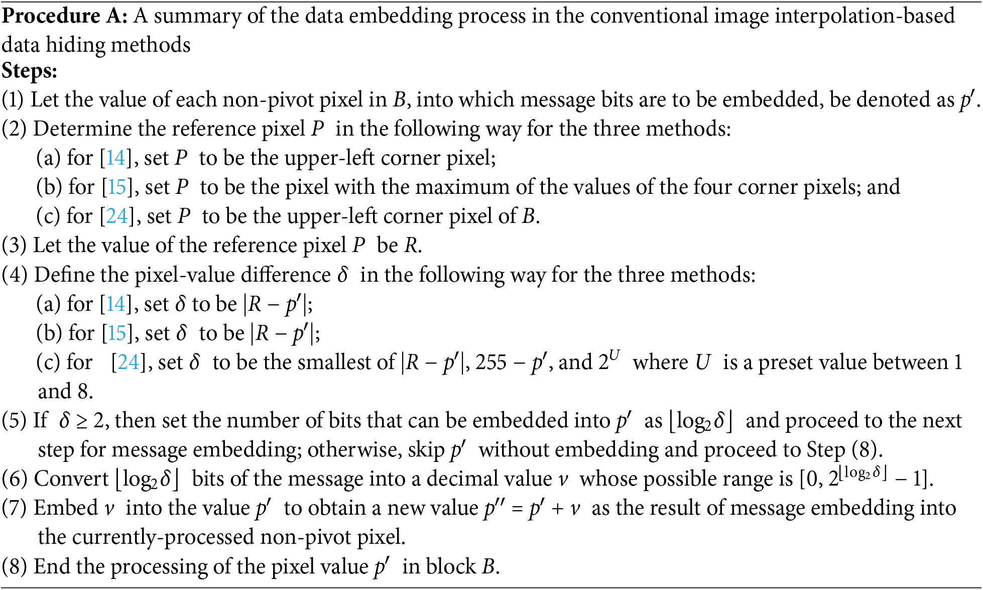
It is noted that to ensure consistent uses of notations for describing the three methods in the above summary, the schemes for determining the pixel-value difference and the number of bits that can be embedded in the NIE-based data hiding method, as proposed in [24] and described previously, are adjusted as described in Steps (4c) and (5) above, but the results obtained after the adjustment are identical to the original ones.
Now, when δ is a power of two, then 2⌊log2δ⌋ equals δ and the possible range [0, 2⌊log2δ⌋ − 1] becomes [0, δ − 1] so that after Step (7) above is carried out, the new pixel value p″ will fall within the range [p′, p′ + δ − 1], allowing the number of embedded bits to reach the maximum.
However, the value of δ is not always a power of two in real applications; in such a case, the possible range of p′′ after embedding the bit value v becomes the subrange [p′, p′ + 2⌊log2δ⌋ − 1], meaning that the subrange [p′ + 2⌊log2δ⌋, p′ + δ − 1] of [p′, p′ + δ − 1] is wasted, resulting in fewer bits being embedded and, consequently, a lower message embedding capacity.
In this study, the technique of multiple-based number conversion is proposed to remove this shortage, improving the data embedding capacity of interpolation-based data hiding like the three methods mentioned above [14,15,24]. Specifically, during the message embedding process dealing with a pixel with value p′ in the cover image, let the absolute differences between p′ and its corresponding reference pixel value be denoted as δ. Instead of taking the number of embedded bits into p′ as ⌊log2δ⌋ as done by the conventional methods to embed the bit value v into p′ to become a new value p″ = p′ + v as described in Steps (5)–(7) of Procedure A above, the proposed improvement method adopts the multiple-based number conversion presented previously to treat each absolute difference value δ as the created base value b of a digit d in a multiple-based number, with d being a remainder in successive integer divisions of the decimal value of the message by the created bases. Finally, the digit d is embedded into p′ as p″ = p′ + d. That is, the proposed improvement method carries out the following outline of message embedding (the detailed algorithms will be presented in the later sections).
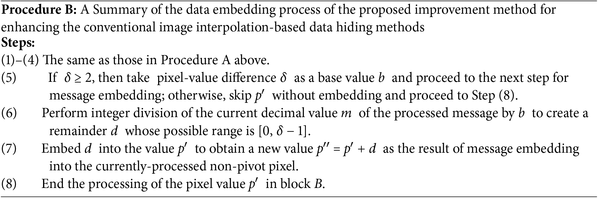
By using Procedure B above, after Step (7) is accomplished, the new pixel value p″ will fall within the range [p′, p′ + δ − 1]. The above-mentioned wasted subrange [p′ + 2⌊log2δ⌋, p′ + δ − 1] of pixel values incurred by Procedure A can now be fully utilized by the proposed improvement method, as proved by the following theorem.
Theorem 1: The number mp of bits embedded by the proposed improvement method into a cover image I is larger than or equal to the number mc of bits embedded by a conventional image interpolation-based data hiding method like [14,15,24], i.e.,
Proof: Assume that the cover image I contains n non-pivot pixels denoted as P0, P1, … , Pn−1 available for secret embedding, where the pixel-value difference defined by the previously-described overview of the data embedding process of conventional image interpolation-based data hiding methods for Pi is δi for i = 0, 1, … , n − 1, where
In a conventional image interpolation-based data hiding method T like [14,15,24], the total number mc of bits embedded in I, as can be seen from Steps (6) and (7) of Procedure A, can be expressed as
In the improvement method that enhances the conventional method T using the proposed multi-based number conversion technique, the total number of embedded bits mp in I can be expressed as
according to aforementioned Property 2 of multi-based number conversion, and can be rewritten as
according to a property of the log function: log(A × B) = log(A) + log(B).
Since the inequality
is a well-known property of the floor function [30], which, when applied iteratively for n times, implies the following inequality:
leading to the following result according to Eqs. (12) and (13):
This completes the proof of the theorem. □
Fig. 8 is an illustration of Theorem 1 for comparing the number of embedded bits in a conventional image interpolation-based data hiding method with the results achievable by the proposed improvement method using different numbers (n) of embeddable non-pivot pixels with randomly generated pixel-value difference values (δ) distributed within the range of 2 to 10.
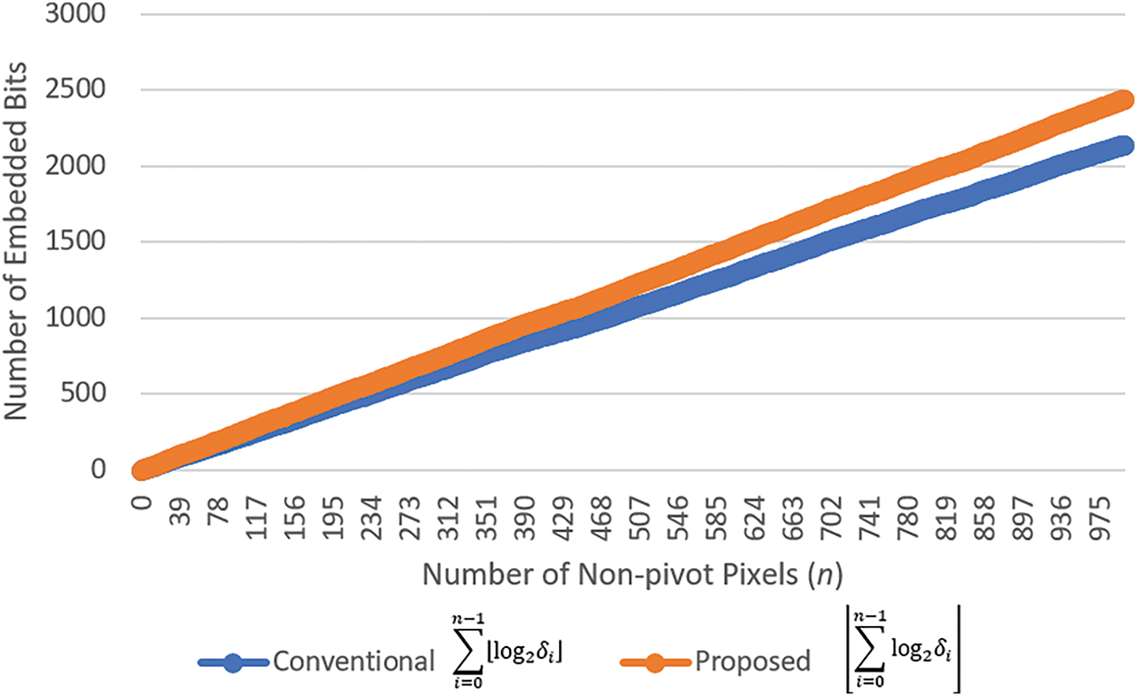
Figure 8: An illustration comparing the number of embedded bits shows that the conventional image interpolation-based data hiding methods achieve
Lemma 1: If the selected bases bn−1, bn−2, … , b0 satisfy the equation
then the n-digit multiple-based number dn−1(bn−1)dn−2(bn−2) … d2(b2)d1(b1)d0(b0) can be used to represent the value of any b-bit binary number.
Proof: According to Property 2 described previously, the n-digit multiple-based number
can be used to represent the value of any b-bit binary number when the following inequality is true:
But it is easy to see that the following inequality is true:
By combining Eqs. (18) and (19), the following inequality can be obtained:
which implies that the following inequality holds:
according to a property of the log function: if log(A) ≥ B, then A ≥ 2B. This completes the proof of the lemma. □
During the hidden data extraction process, the base values b0, b1, … , bn−1 of the multiple-based number system are recalculated based on the absolute pixel value differences δi between the n pixels in the aforementioned conceptually recovered cover image available for message extraction and their corresponding reference pixel values, where i = 0, 1, … , n − 1. Subsequently, the pixel-value differences between the embedded message pixels in the stego image and the corresponding pixels in the cover image are computed for each block, and these differences are used as the digit values d0, d1, … , dn−1 of the extracted multiple-based number represented as
which is finally converted into a binary number as the retrieved secret message in the form of a binary bit string.
3.2 Improvement of the NMI-Based Data Hiding Method by Multiple-Based Number Conversion
In this section, the proposed enhancement of the NMI-based data hiding method using multiple-based number conversion is presented in detail, followed by the detailed descriptions of the message embedding process and the extraction processes of the improved NMI-based data hiding method.
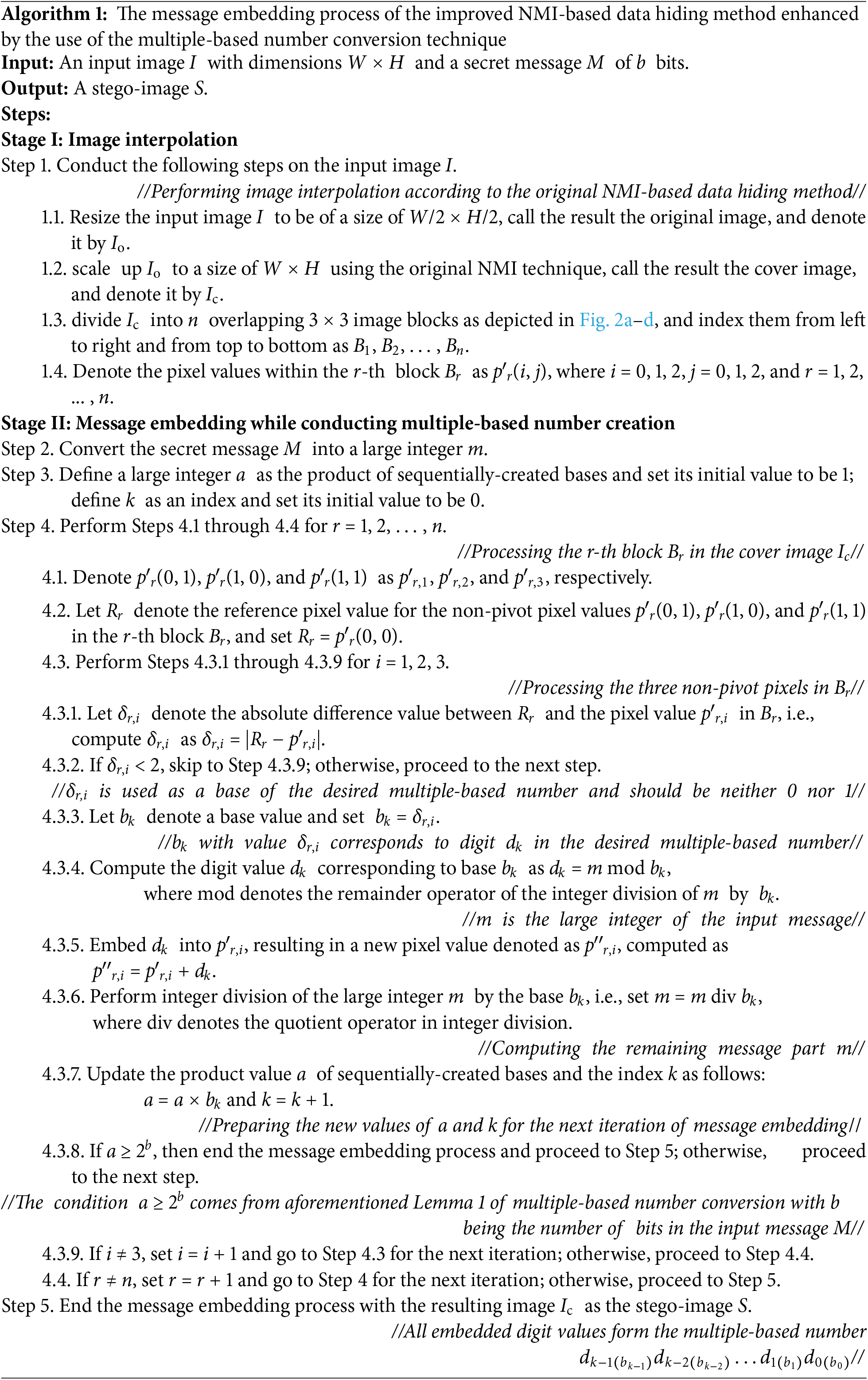
The message embedding process of the improved NMI-based data hiding method begins with generating a cover image using the interpolation scheme of the original NMI-based data hiding method. Then, the secret message to be embedded is converted into a large integer, followed by successive integer divisions with the base values being the absolute difference values between the value p′(0, 0) of the reference pixel and the values of the newly generated non-pivot pixels in each block of the cover image, yielding a multiple-based number. Finally, the digit values in the resulting multiple-based number are embedded respectively into the non-pivot pixels associated with the corresponding base values.
(a) The Message Embedding Algorithm (Algorithm 1)
(b) An Example of Applying Algorithm 1 for Message Embedding
An example of applying Algorithm 1 for embedding a given message into a cover image Ic obtained in Stage I of the above algorithm is illustrated in Fig. 9 with the computations of the intermediate results being described in the following. The image Ic is divided into two overlapping 3 × 3 blocks for data embedding in Step 1.3 of the algorithm. Assume that the message to be embedded is a binary string
of the length b = 17. This bit string is first converted into a large integer m = 50,843 as done by Step 2 of the algorithm. Also, a is set to be 1 in Step 3.
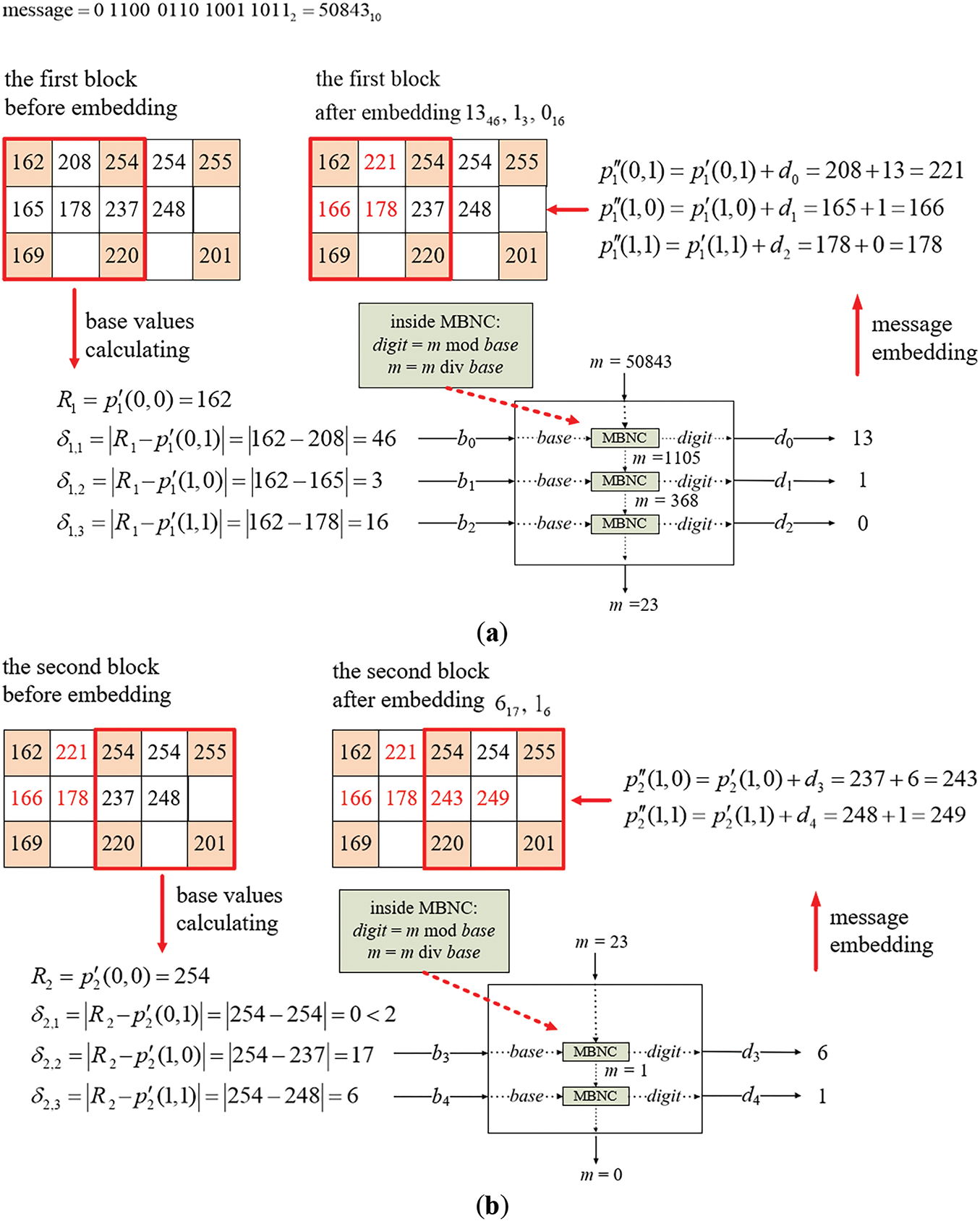
Figure 9: Illustration of an example of applying Algorithm 1 to embed a binary message string into a two-block cover image. (a) The embedding process for the first block. (b) The embedding process for the second block
(i) Embedding Message Bits into the First Block
Initially, the base values corresponding to the pixel values designated for message embedding in the first block of the cover image Ic shown at the left of Fig. 9a are identified by Steps 4.1, 4.2, and 4.3.1–4.3.3. Specifically, with the non-pivot pixel values p′1(0, 1), p′1(1, 0), and p′1(1, 1) which are 208, 165, and 178, respectively, and the reference pixel value R1 = p′1(0, 0) which is 162, the absolute difference values between R1 and the values of the non-pivot pixels are calculated to be δ1,1 = |162 − 208| = 46, δ1,2 = |162 − 165| = 3, and δ1,3 = |162 − 178| = 16. Since all the three difference values are greater than or equal to 2, they are appropriate, as required by Step 4.3.2, to be used as base values b0 = 46, b1 = 3, and b2 = 16 for embedding the corresponding digits of the multiple-based number.
Then, as carried out by the operations described in Steps 4.3.4 and 4.3.6, the large integer m (used to generate digits to be embedded) is divided sequentially by the corresponding base values b0, b1, and b2 using successive integer divisions. The serial remainders obtained from these divisions are used as the digit values d0, d1, and d2 of the desired multiple-based number. Finally, these digit values are embedded into p′1(0, 1), p′1(1, 0), and p′1(1, 1), respectively, as described by Step 4.3.5. More details of this message embedding process are presented in the following.
1. By d0 = m mod b0, the first digit d0 in the multiple-based number is computed to be 50,843 mod 46 = 13 which is embedded into p′1(0, 1) by adding d0 to p′1(0, 1) to obtain the new pixel value p″1(0, 1) = 208 + 13 = 221.
2. The value of m is updated to be m div b0 = 50,843 div 46 = 1,105, the product value a of the sequentially-created bases is updated to be a × b0 = 1 × 46 = 46, and the result 46 is checked to be smaller than 2b = 217 = 131,072, as done in Steps 4.3.6–4.3.8, meaning that more message bit embedding may be continued.
3. By d1 = m mod b1, the second digit d1 is computed to be 1,105 mod 3 = 1 which is embedded into p′1(1, 0) by adding d1 to p′1(1, 0) to obtain the new pixel value p″1(1, 0) = 165 + 1 = 166.
4. The value of m is updated to be m div b1 = 1,105 div 3 = 368, and that of a to be a × b1 = 46 × 3 = 138 with 138 < 217 = 131,072 being checked, meaning that more message-bit embedding may be continued.
5. By d2 = m mod b2, the third digit d2 is computed to be 368 mod 16 = 0 which is then embedded into p′1(1, 1) by adding d2 to p′1(1, 1) to obtain the new pixel value p″1(1, 1) = 178 + 0 = 178.
6. The value of m is updated to be m div b2 = 368 div 16 = 23, and that of a to be a × b2 = 138 × 16 = 2,208 < 217 = 131,072, meaning that more embedding may be continued by processing the second block as shown in Fig. 9b.
At the end of embedding in the first block, the embedded digits are d0(b0), d1(b1), and d2(b2), namely 1346, 13, and 016, respectively, with the values of m and a being 23 and 2,208.
(ii) Embedding Message Bits in the Second Block
The embedding process is then performed similarly on the second block of the cover image Ic as illustrated in Fig. 9b. The non-pivot pixel values used for embedding in this block are p′2(0, 1), p′2(1, 0), and p′2(1, 1), which are 254, 237, and 248, respectively, while the reference pixel value R2 is p′2(0, 0) = 254. The absolute differences are calculated to be δ2,1 = |254 − 254| = 0, δ2,2 = |254 − 237| = 17, and δ2,3 = |254 − 248| = 6. Only the second and third differences are greater than or equal to 2, and so are used as the fourth and fifth base values b3 = 17 and b4 = 6. Two digits d3, and d4 obtained as the remainders resulting from dividing m by b3 and b4 successively are then embedded into p′2(1, 0), and p′2(1, 1), respectively. The details are described in the following, as a continuation of those of processing the first block.
7. By d3 = m mod b3, the fourth digit d3 is computed to be 23 mod 17 = 6, which is embedded into p′2(1, 0) by adding d3 to p′2(1, 0) to obtain the new pixel value p″2(1, 0) = 237 + 6 = 243.
8. The value of m is updated to be m div b3 = 23 div 17 = 1, and that of a to be a × b3 = 2,208 × 17 = 37,536 < 217 = 131,072, meaning that more message bit embedding may be continued.
9. By d4 = m mod b4, the fifth digit d4 is computed to be 1 mod 6 = 1, which is then embedded into p′2(1, 1) by adding d4 to p′2(1, 1) to obtain the new pixel value p″2(1, 1) = 248 + 1 = 249.
10. The value of m is updated to be m div b4 = 1 div 6 = 0, and that of a to be a × b4 = 37,536 × 6 = 225,216 ≥ 217 = 131,072, indicating that the 17-bit secret message has been fully embedded and the algorithm is stopped according to Step 4.3.8.
As a result, the digits embedded in the second block are d3(b3) and d4(b4), namely 617 and 16. Consequently, the entire secret message embedded into the two blocks forms the multiple-based number 16617016131346.
The message extraction process of the proposed improved NMI-based data hiding method begins with conceptually recovering the cover image from the input stego-image using the NMI technique. The conceptually-recovered cover image is identical to that produced during the embedding process. The stego-image and cover image are then synchronously divided into overlapping 3 × 3 blocks for message extraction. Subsequently, by the proposed improvement method, the base values corresponding to the digit values of the multiple-based number to be found in each block are derived from the recovered cover image. The digit values corresponding to these base values are then extracted using the pixel values of the stego-image and their corresponding pixel values in the cover image. The base values and the digit values are combined to form the desired multiple-based number, which is finally converted into a bit string of the same length as the embedded secret message, thereby completing the extraction of the secret information. The detailed extraction procedure of the improved NMI-based data hiding method is presented in the following.
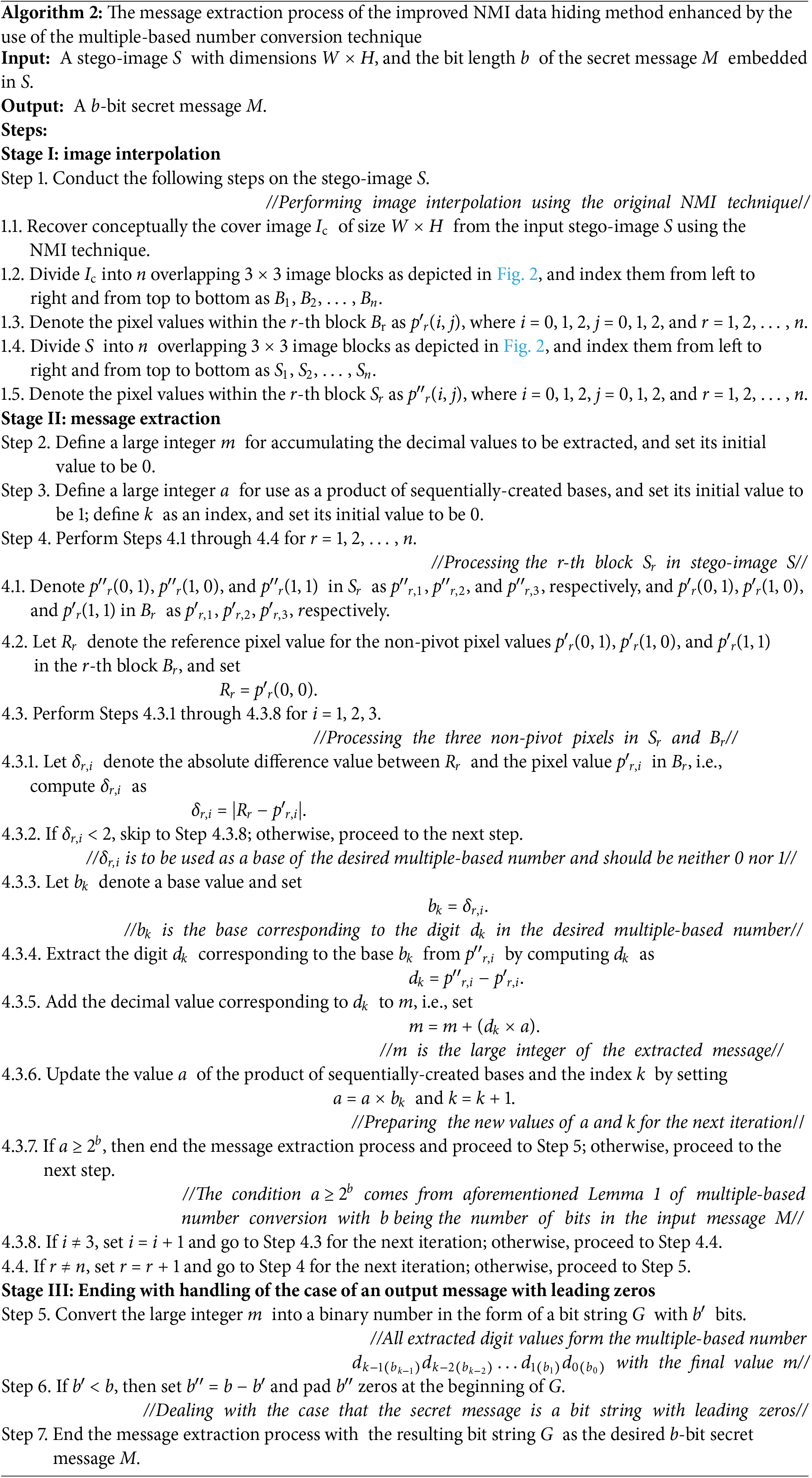
(a) The Message Extraction Algorithm (Algorithm 2)
(b) An Example of Applying Algorithm 2 for Message Extraction
An example of applying Algorithm 2 for message extraction from a stego-image that is yielded by Algorithm 1 as illustrated in Fig. 9 is shown in Fig. 10 with the computations of the intermediate results being described in the following. The process begins with conceptually recovering the cover image Ic from the stego-image S using the original NMI technique, as carried out by Step 1.1 of Algorithm 2. Both S and Ic are divided into two 3 × 3 blocks for data extraction by Steps 1.2 and 1.4. Also, m is set to be 0 in Step 2 and a is set to be 1 in Step 3. More details of the message extraction process are described in the following.
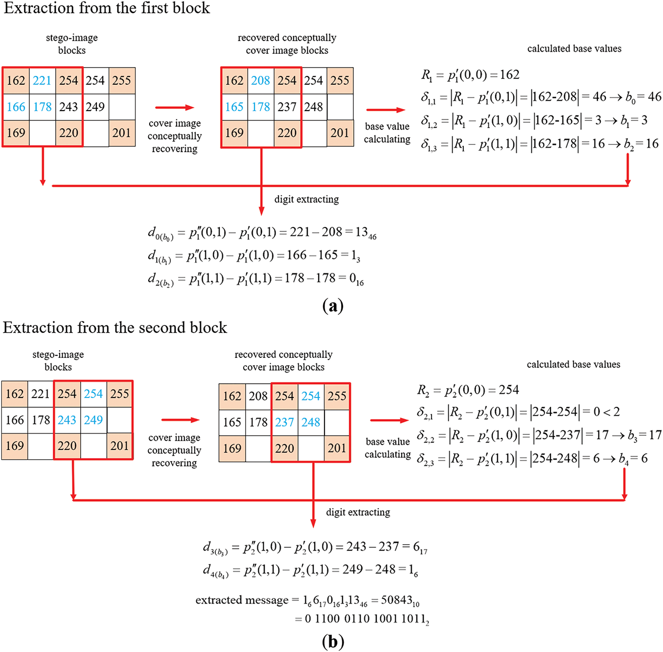
Figure 10: Illustration of an example of applying Algorithm 2 to extract a binary message string from a two-block stego-image. (a) The extraction process for the first block. (b) The extraction process for the second block
(i) Extraction of the Message Bits from the First Block
Initially, the base values are recovered from the non-pivot pixel values in the first block of the conceptually-recovered cover image Ic by Steps 4.1, 4.2 and 4.3.1–4.3.3, as illustrated at the right of Fig. 10a. Specifically, with the non-pivot pixel values p′1(0, 1), p′1(1, 0), and p′1(1, 1) being 208, 165, and 178, respectively and the reference pixel value R1 = p′1(0, 0) being 162, the absolute differences between R1 and the non-pivot pixels’ values are calculated to be δ1,1 = |162 − 208| = 46, δ1,2 = |162 − 165| = 3, and δ1,3 = |162 − 178| = 16. Since all these three differences are greater than or equal to 2, they are appropriate, as required by Step 4.3.2, to be used as the base values b0 = 46, b1 = 3, b2 = 16 for extracting the corresponding digits of the multiple-based number to be found out.
Then, as carried out by the operations of Step 4.3.4, the differences between the stego-image pixel values p″1(0, 1), p″1(1, 0), and p″1(1, 1) as well as the corresponding cover image pixel values p′1(0, 1), p′1(1, 0), and p″1(1, 1) are computed to extract the digits d0, d1, and d2 of the multiple-based number. The detailed extraction steps are described as follows.
1. By d0 = p″1 (0, 1) − p′1(0, 1), the first digit d0 in the multiple-based number is computed to be p″1(0, 1) − p′1(0, 1) = 221 − 208 = 13.
2. The value of m is updated to be m + (d0 × a) = 0 + (13 × 1) = 13, and the product value a of sequentially-created bases to be a × b0 = 1 × 46 = 46 which is checked to be smaller than the value 2b = 217 = 131,072, as done in Steps 4.3.5–4.3.7, meaning that more message bit extraction may be continued.
3. By d1 = p″1(1, 0) − p1′(1, 0), the second digit d1 is computed to be 166 – 165 = 1.
4. The value of m is updated to be m + (d1 × a) = 13 + (1 × 46) = 59, and that of a to be a × b1 = 46 × 3 = 138 < 217 = 131,072, meaning that more extraction may be continued.
5. By d2 = p″1(1, 1) − p1′(1, 1), the third digit d2 is computed to be 178 − 178 = 0.
6. The value of m is updated to be m + (d2 × a) = 59 + (0 × 138) = 59, and that of a to be a × b2 = 138 × 16 = 2,208 = 2,208 < 217 = 131,072, meaning that more extraction may be continued by processing the second block as shown in Fig. 10.
At the end of the process of extraction from the first block, the extracted digits are d0(b0), d1(b1), and d2(b2), namely 1346, 13, and 016, with the values of m and a being 59 and 2,208.
(ii) Extraction of the Message Bits from the Second Block
The extraction process is then performed similarly on the second block of the stego-image S as illustrated in Fig. 10b. Additional base values of the multiple-based number are recovered from non-pivot pixel values in the second block of the recovered cover image Ic by Steps 4.1, 4.2 and 4.3.1–4.3.3, as shown at the right of Fig. 10b. Specifically, with the non-pivot pixel values p′2(0, 1), p′2(1, 0), and p′2(1, 1) which are 254, 237, and 248, respectively, and the reference pixel value R2 = p′2(0, 0) which is 254, the absolute difference values between the latter values and the former ones are calculated to be δ2,1 = |254 − 254| = 0, δ2,2 = |254 − 237| = 17, and δ2,3 = |254 – 248| = 6. Only the second and third difference values are greater than or equal to 2, and so they are used as the fourth and fifth base values b3 = 17 and b4 = 6 for extracting the corresponding digits of the desired multiple-based number. Accordingly, the difference values between the stego-image pixel values p″2(1, 0), and p″2(1, 1) and the corresponding cover image pixel values p′2(1, 0), and p′2(1, 1) are computed to extract respectively the digits d3, and d4 of the multiple-based number. The details are described in the following, as a continuation of those of processing the first block described previously.
7. By d3 = p″2(1, 0) − p′2(1, 0), the fourth digit d3 is computed to be 243 − 237 = 6.
8. The value of m is updated to be m + (d3 × a) = 59 + (6 × 2,208) = 13,307, and that of a to be a × b3 = 2,208 × 17 = 37,536 < 217 = 131,072, meaning that more extraction may be continued.
9. By d4 = p″2(1, 1) − p′2(1, 1), the fifth digit d4 is computed to be 249 − 248 = 1.
10. The value of m is updated to be m + (d4 × a) = 13,307 + (1 × 37,536) = 50,843, and that of a to be a × b4 = 37,536 × 6 = 225,216 ≥ 217 = 131,072, indicating that the 17-bit secret message has been fully extracted and the algorithm is stopped according to Step 4.3.7.
As a result, the digits extracted from the second block are d3(b3) and d4(b4), namely 617 and 16. Consequently, the entire secret message extracted from the two blocks forms the multiple-based number 16617016131346. The value of m = 50,843 is finally converted to be a bit string G = 11000110100110112 with 16 bits. After padding one zero bit at the beginning of G by Step 6 of the algorithm, the entire 17-bit binary secret message 011000110100110112 is obtained.
4 Excremental Results and Discussions
The experimental environment used in this study consisted of an Intel i7-10700 CPU, 16 GB of memory, and Microsoft Visual Studio 2019, with the implementation conducted using the C# programming language. For large integer processing, the BigInteger class from the System.Numerics namespace was employed. Six 512 × 512 grayscale images—Baboon, Jet, Peppers, Boat, Tree, and House—were used as input images, as shown in Fig. 11. A randomly generated binary string was consistently used for secret message embedding in all the experiments conducted in this study.
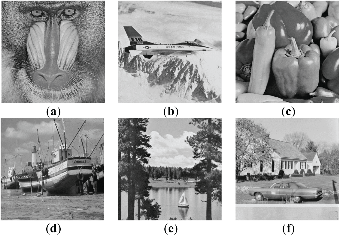
Figure 11: Tested input images. (a) Baboon. (b) Jet. (c) Peppers. (d) Boat. (e) Tree. (f) House
4.1 Comparisons with the Original NMI-, INP-, and NIE-Based Data Hiding Methods and the Methods Utilizing the Proposed Improvement
At first, by using each of the three original NMI-, INP-, and NIE-based data hiding methods [14,15,24] as well as their improved versions generated by applying the improvement technique based on multiple-based number conversion as proposed in this study, each previously-mentioned tested image is embedded with the maximum possible number of bits coming from the randomly generated binary string. The results are shown in Table 1, from which it can be seen that the proposed method yields better message embedding rates than the original NMI-, INP-, and NIE-based data hiding methods. Here, the embedding rate of an image is defined as

Specifically, for NMI-based data hiding, the proposed improvement technique increases the embedding rate of the original method by an average of 14.69%. For INP- and NIE-based data hiding, the proposed improvement technique achieves average increases of 13.74% and 10.87%, respectively. In summary, the improvement technique proposed in this study yields embedding rates that are, on average, 10% to 14% higher than those of the three original methods.
Furthermore, two metrics, PSNR (peak signal-to-noise ratio) and SSIM (structural similarity index measure) [31], were used to evaluate the quality of the resulting stego-images. Here, SSIM is a widely used metric with values ranging from 0 to 1, where a higher score indicates greater structural similarity between images. The stego-images created by the proposed improvement technique are inferior in this aspect to those yielded by the three conventional NMI-, INP-, and NIE-based data hiding methods as can be seen from Figs. 12 and 13. However, as can be seen from Fig. 14, the stego-images of the Baboon created by the proposed improvement technique look almost of no visual difference from those yielded by the conventional methods. This phenomenon can also be seen from the quality of the stego-images of the Jet, as shown in Fig. 15. That is, the degradations of the stego-images yielded by the proposed improvement technique are limited.
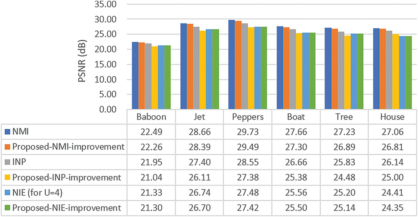
Figure 12: The PSNR values of images yielded by the three original data hiding methods and the methods utilizing the proposed improvement technique
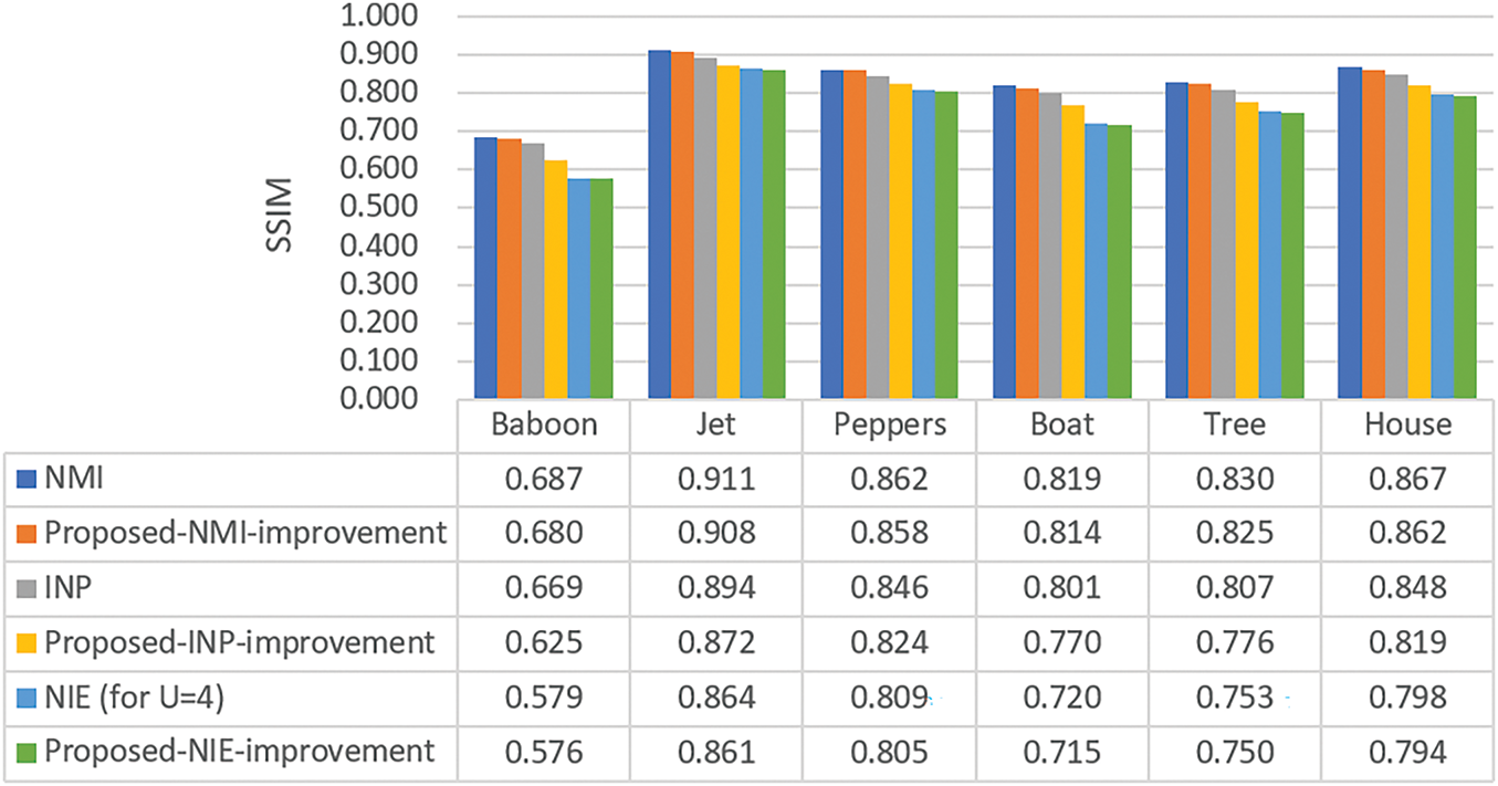
Figure 13: The SSIM values of images yielded by the three original data hiding methods and the methods utilizing the proposed improvement technique
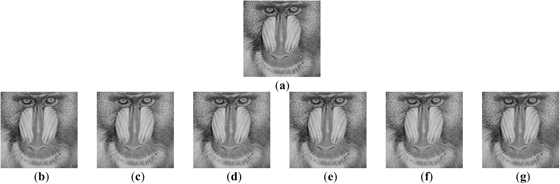
Figure 14: The stego-images generated by embedding secret messages into the image shown in Fig. 11a of the Baboon using the original NMI-, INP-, and NIE-based data hiding methods [14,15,24], as well as the methods resulting from using the improvement technique proposed in this study. (a) Original Image. (b) The images yielded by the original NMI-based data hiding method. (c) The images yielded by the original INP-based data hiding method. (d) The images yielded by the original NIE-based data hiding method (for U = 4). (e) The images yielded by the improved NMI-based data hiding method. (f) The images yielded by the improved INP-based data hiding method. (g) The images yielded by the improved NIE-based data hiding method (for U = 4)
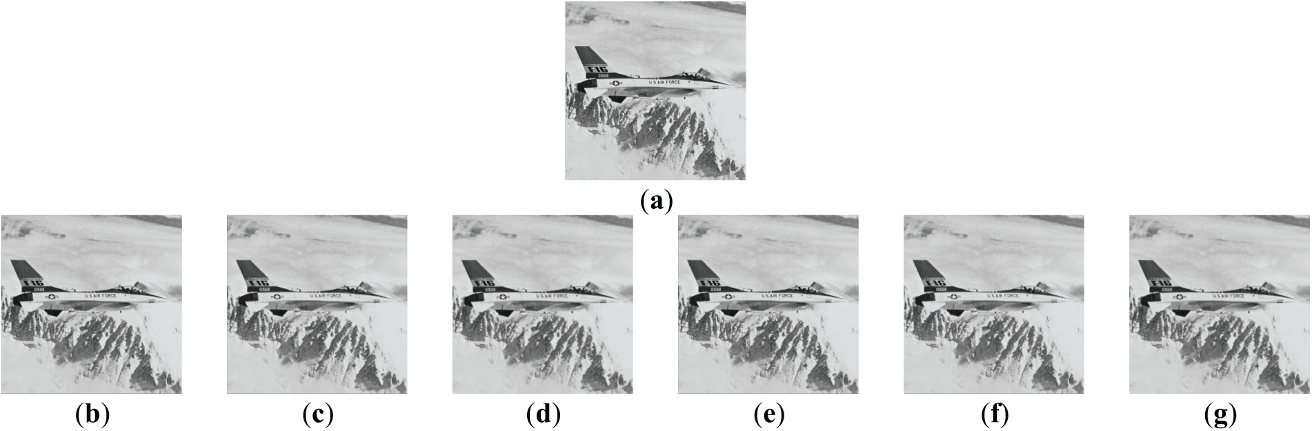
Figure 15: The stego-images generated by embedding secret messages into the image shown in Fig. 11b of the Jet using the original NMI-, INP-, and NIE-based data hiding methods [14,15,24], as well as the methods resulting from using the improvement technique proposed in this study. (a) Original Image. (b) The images yielded by the original NMI-based data hiding method. (c) The images yielded by the original INP-based data hiding method. (d) The images yielded by the original NIE-based data hiding method (for U = 4). (e) The images yielded by the improved NMI-based data hiding method. (f) The images yielded by the improved INP-based data hiding method. (g) The images yielded by the improved NIE-based data hiding method (for U = 4)
4.2 Comparison of the Embedding Rates between the Original NIE-Based Methods and the Methods Utilizing the Proposed Improvement, under Different U Values
Additionally, the comparisons of the embedding rates yielded by the original NIE-based data hiding method under different U values with those yielded the method that incorporates the proposed improvement technique for two selected images, Fig. 11a,b, are shown in Fig. 16. It can be seen from the figure that as U increases, both the original NIE-based data hiding method and the proposed improvement method yield increasing embedding rates. However, the proposed improvement method consistently achieves higher rates than the original method. This phenomenon further demonstrates the superiority of the proposed method in embedding-rate performance.
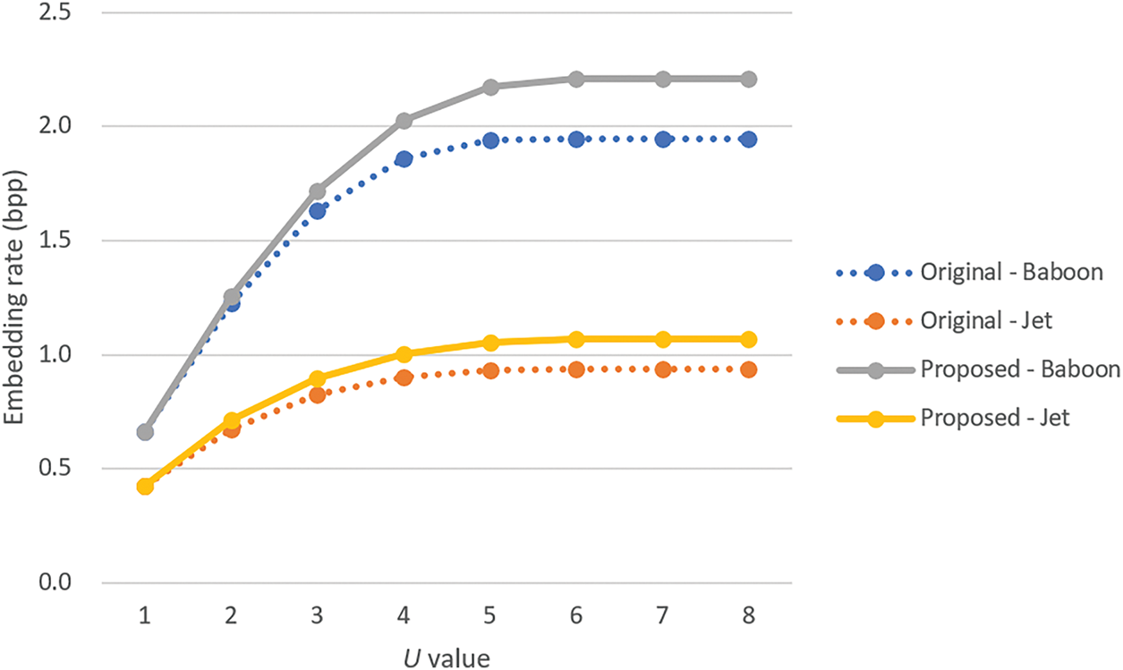
Figure 16: Comparison of the embedding rates between the original NIE-based methods and the methods resulting from using the improvement technique proposed in this study for two images, the Baboon in Fig. 11a and the Jet in Fig. 11b, under different U values
4.3 Security Evaluation by RS Steganalysis
The RS steganalysis method, a dual-statistics approach introduced by Fridrich et al. [32], was utilized to assess the security of the stego-images generated by the proposed method in this study. Figs. 17a–c and 18a–c present the RS diagrams created from the stego-images shown in Figs. 14e–g and 15e–g, respectively. These stego-images were generated by embedding secret messages into the images shown in Fig. 11a (Baboon) and Fig. 11b (Jet), respectively. The embedding process was performed using the improved NMI-, INP-, and NIE-based data hiding methods presented previously.
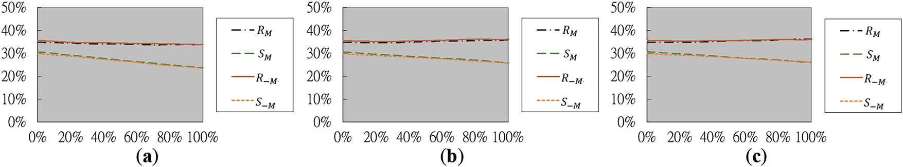
Figure 17: The RS diagrams yielded by RS steganalysis for the images in Fig. 14e–g of the Baboon. (a) Diagram generated from Fig. 14e yielded by the improved NMI-based data hiding method. (b) Diagram generated from Fig. 14f yielded by the improved INP-based data hiding method. (c) Diagram generated from Fig. 14g yielded by the improved NIE-based data hiding method
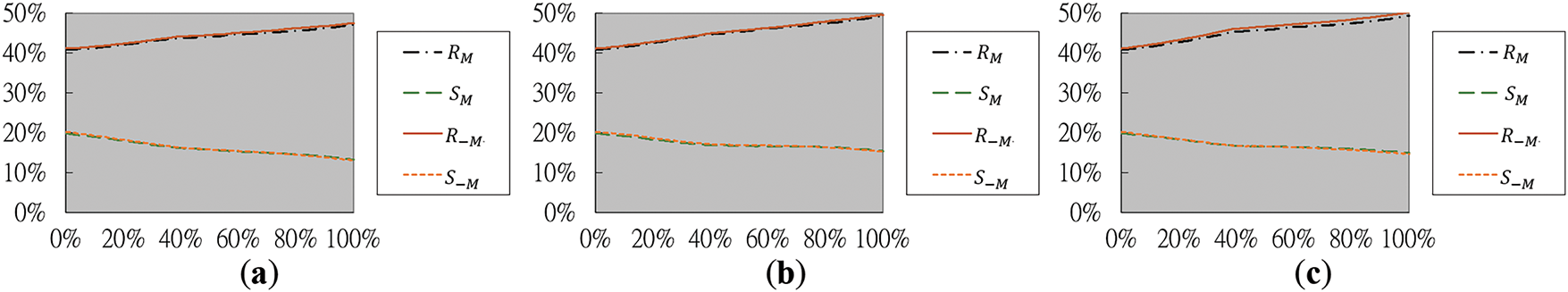
Figure 18: The RS diagrams yielded by RS steganalysis for the images in Fig. 15e–g of the Jet. (a) Diagram generated from Fig. 15e yielded by the improved NMI-based data hiding method. (b) Diagram generated from Fig. 15f yielded by the improved INP-based data hiding method. (c) Diagram generated from Fig. 15g yielded by the improved NIE-based data hiding method
In these RS diagrams, the horizontal x-axis represents the percentage of image pixels containing embedded secret messages, while the vertical y-axis shows the proportions of regular and singular pixel groups associated with the masks M = [0 1 1 0] and −M = [0 −1 −1 0]. Specifically, each pixel group is defined as G = (x1, x2, x3, x4), where x1 through x4 are four adjacent pixels for analysis. To evaluate the smoothness of G, a discriminant function is used: f(G) = |x1 − x2| + |x2 − x3| + |x3 − x4|, which measures the local variation at G. The masks M and −M modify respectively the pixel values of G to be G′ = (x1, x2 + 1, x3 + 1, x4) and G′ = (x1, x2 − 1, x3 − 1, x4). Accordingly, the pixel group G is treated as regular (denoted as R) if the smoothness function value increases after applying the mask, i.e., if f(G′) > f(G); as singular (denoted as S) if the smoothness function value decreases, i.e., if f(G′) < f(G); and as unusable (denoted as U) if the smoothness function value remains unchanged, i.e., if f(G′) = f(G). If the RS steganalysis method identifies the existence of hidden data, the curves
Accordingly, the analysis in Figs. 17 and 18 shows that in all tested cases, the curves
4.4 Limitation of the Proposed Method
Despite its advantages, the proposed method has several limitations that should be acknowledged. First, the integration of multiple-based number conversion introduces additional computational complexity to both the embedding and extraction processes when compared to simpler bit-based approaches. This increased complexity results in greater processing overhead, as converting messages to and from a multiple-based number system demands more processing time and memory. Such requirements could be disadvantageous in applications where time efficiency or limited system resources are critical. Moreover, the method is inherently tailored to interpolation-based data hiding techniques and is not directly applicable to other widely used methods such as those operating in the transform domain, including DCT or DWT-based approaches. A third common limitation is that when the absolute difference value δ is small (i.e., when δ < 2) as is often observed in smooth images, the proposed method, like other conventional interpolation-based methods, does not embed secret data into the involved non-pivot pixel, resulting in less embedding capacity. However, if alternative techniques (e.g., the LSB substitution method) have been used in some conventional methods to increase embedding capacity even when δ < 2, then the proposed method can also employ the same techniques under the same circumstances. Lastly, the proposed method may not be appropriate for serious real-time environments or on resource-constrained platforms such as mobile or embedded systems.
In the NMI-, INP-, and NIE-based data hiding methods [14,15,24] that have been enhanced using this improvement approach in this study, secret messages are embedded into the non-pivot pixels of the cover image, and a reference pixel value is defined for use in the message embedding process to compute an absolute difference value, denoted as δ. Based on the use of δ, most image interpolation-based data hiding techniques, including the three aforementioned methods, embed ⌊log2δ⌋ bits of the input secret message into each non-pivot pixel, thereby generating a stego-image containing the hidden message.
In contrast, the enhancement of each of the three aforementioned methods by the proposed improvement method is achieved by embedding
The proposed method as well as the three interpolation-based data hiding methods examined in detail in this study do not specify how the message length b is transmitted, because this aspect was usually considered outside the core focus of the problem. Usually the value b is needed for message extraction, and a common approach is to convert b into a fixed-length binary string (e.g., 32 bits), and embed it into the image using a standard embedding method (e.g., the LSB substitution method) before the secret message is embedded.
Furthermore, it is mentioned that the message embedding capacities of image interpolation-based data hiding methods that embed ⌊log2δ⌋ bits into each non-pivot pixel in the cover image based on the use of the absolute difference value δ other than the three methods mentioned above (such as those in [21,23,33–35]) may also be enhanced by the proposed improvement method. The emphasis is that the proposed method can enhance the message embedding capacity of n non-pivot pixels from
Finally, about the computational complexity mentioned above, specifically the execute times of message embedding yielded by the original NMI-, INP-, and NIE-based data hiding methods [14,15,24] as well as the methods utilizing the proposed improvement technique for two selected images, Fig. 11a,c, are shown in Fig. 19. In general, the time complexity of the execution time vs. the embedded message size n of the proposed improvement technique can be analyzed to be O(n2), which arises from the need to perform O(n) sequential divisions on the large integer value represented by the entire secret message with each division requiring O(n) computation time. In contrast, a conventional bit-based embedding method requires direct sequential fetches of the necessary bits from the secret message with the total complexity of O(n).
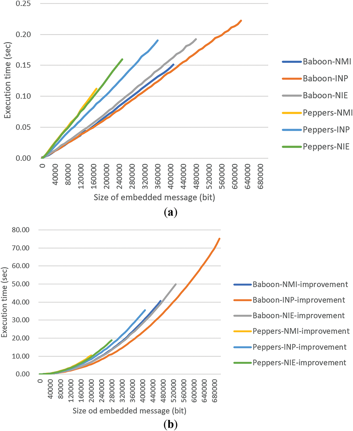
Figure 19: The graphs of execution times of message embedding yielded by the original NMI-, INP-, and NIE-based [14,15,24] data hiding methods as well as the methods utilizing the proposed improvement technique in this study for two images, the Baboon in Fig. 11a and the Peppers in Fig. 11c. (a) The execution-time graph of the original data hiding methods. (b) The execution-time graph of the methods utilizing the proposed improvement technique
5 Conclusions and Future Works
A general approach has been proposed to enhance the message embedding capacity of various image interpolation-based data hiding methods. Specifically, three well-known data hiding methods—namely, the NMI-, INP-, and NIE-based methods—have been enhanced using this improvement approach in this study. In these three methods, secret messages are embedded into non-pivot pixels using a reference pixel to compute an absolute difference value, denoted as
Experiments have been conducted to evaluate the effectiveness of the proposed enhancement method. The resulting embedding rates increased by approximately 14%, 13%, and 10% when compared respectively with those yielded by the NMI-, INP-, and NIE-based data hiding methods. Furthermore, experimental results indicate that the stego-image quality yielded by the proposed method does not degrade significantly, both visually and in terms of PSNR and SSIM metrics. Additionally, RS steganalysis has also been performed to demonstrate the security of the proposed method. Finally, the proposed improvement method is also expected to enhance the data embedding capabilities of many other image interpolation-based data hiding techniques that use power-of-two pixel-value ranges, beyond the three tested in this study. For future works, it is suggested as potential directions to evaluate the robustness of the proposed method against modern deep learning-based or frequency-domain attacks, and to apply the multiple-based number conversion technique to a wider set of methods or image types.
Acknowledgement: The authors would like to thank the Department of Computer and Communication Engineering, National Kaohsiung University of Science and Technology, Taiwan, for providing the necessary facilities and resources to conduct this research.
Funding Statement: The authors received no specific funding for this study.
Author Contributions: The authors confirm contribution to the paper as follows: Conceptualization, Da-Chun Wu and Bing-Han Sie; methodology, Da-Chun Wu; software, Bing-Han Sie; validation, Da-Chun Wu and Bing-Han Sie; formal analysis, Da-Chun Wu; investigation, Da-Chun Wu and Bing-Han Sie; data curation, Bing-Han Sie; writing—original draft preparation, Da-Chun Wu and Bing-Han Sie; writing—review, editing, and supervision, Da-Chun Wu. All authors reviewed the results and approved the final version of the manuscript.
Availability of Data and Materials: The data that supports the findings of this study are available from the corresponding author upon reasonable request.
Ethics Approval: Not applicable.
Conflicts of Interest: The authors declare no conflicts of interest to report regarding the present study.
Appendix A A Review of the INP-Based Data Hiding Method
The INP-based data hiding method proposed by Lee and Huang [15] extends the NMI-based approach [14] with the aim of improving message embedding capacity. Just like the NMI-based method, the INP-based method at first scales down the input image I with dimensions W × H to be an original image Io. of size (W/2) × (H/2). Then, a cover image Ic of size W × H is scaled up for further use in the data hiding process.
Following a similar approach to the NMI [14] method, the pixel values at the four corners—p′(0, 0), p′(0, 2), p′(2, 0), and p′(2, 2)—of each 3 × 3 block in the cover image Ic are assigned the corresponding values from the 2 × 2 block in the original image Io, specifically p(0, 0), p(0, 1), p(1, 0), and p(1, 1), respectively.
Subsequently, the values of the newly generated pixels p′(0, 1), p′(1, 0), and p′(1, 1) within each 3 × 3 block of the cover image Ic are determined using an interpolation method distinct from that of the NMI approach, as described below:
Compared with the equations of Eq. (2) of the interpolation results yielded by the NMI, those in Eq. (A1) shows that the INP significantly increases the weighting of the value p(0, 0) of the upper-left corner pixel in the original image block when computing the values of the non-pivot pixels, p′(0, 1), p′(1, 0), and p′(1, 1).
In the INP-based data hiding method, the non-pivot pixels within each 3 × 3 block of the cover image are utilized to embed the secret message as in the NMI-based method. Unlike the NMI-based method, in the INP-based method, the corner pixel in each 3 × 3 block with the maximum value among those of the four corner pixels, p′(0, 0), p′(0, 2), p′(2, 0), and p′(2, 2), in each 3 × 3 block is selected to be the reference pixel P, meaning that the reference pixel value R of P is set to be
Once the reference pixel value R is determined, the subsequent data embedding and extraction procedures in the INP-based data hiding method follow a process similar to that of the NMI-based approach. Therefore, detailed explanations are omitted here.
Appendix B A Review of the NIE-Based Data Hiding Method
The NIE-based data hiding method, proposed by Mohammad et al. [24], is one of the more recent improvements on the NMI-based data hiding method [14], offering enhanced secret message embedding capacity. Unlike the NMI-based method, the NIE-based method at first scales down the input image I with dimensions W × H to be an image of size (W/2 + 1) × (H/2 + 1), referred to as the original image Io. Then, an image Ii of size (W + 1) × (H + 1) is generated from Io using an interpolation technique. All the pixels in the rightmost column and bottommost row of Ii are discarded to obtain an image Ic called the cover image with dimensions W × H for further use in the data hiding process.
Just like the NMI [14] and INP [15] techniques, the pixel values p′(0, 0), p′(0, 2), p′(2, 0), and p′(2, 2) of the four corners of each 3 × 3 block in the cover image Ic are respectively assigned the values p(0, 0), p(0, 1), p(1, 0), and p(1, 1) of the four corners of the corresponding 2 × 2 block in the original image Io:
Next, the newly generated pixels’ values p′(0, 1), p′(1, 0), and p′(1, 1) in each 3 × 3 block of the cover image Ic are computed according to an interpolation technique different from the NMI and INP as follows:
Compared with Eq. (2) of the NMI technique and those in Eq. (A1) of the INP technique, Eq. (A3) shows that weights are assigned by the NIE technique to the pixel values of all the four corners in each 3 × 3 block when calculating the three newly generated pixels’ values p′(0, 1), p′(1, 0), and p′(1, 1).
When embedding a secret message, the number of bits embeddable in each of p′(0,1), p′(1, 0), and p′(1,1) is calculated separately by two steps. first, to prevent overflows to occur while embedding the message bits, the following three difference values δi with i = 1, 2, 3 are calculated:
where min(.) denotes the function of selecting the minimum value. It is worth mentioning that overflows do not occur and need not be prevented in the NMI- and INP-based data hiding methods during message embedding.
Also, the number ni with i = 1, 2, 3 of bits embeddable in the newly generated pixels’ values p′(0, 1), p′(1, 0), and p′(1, 1), respectively, are computed as
where U is a preset maximum number of bits for message embedding, constrained by 1 ≤ U ≤ 8, to limit the embedding amount and maintain image quality. The subsequent data embedding steps and the data extraction process of the NIE-based data hiding method are similar to the typical image interpolation-based data hiding methods and will not be elaborated further here.
Note that the scheme described above for calculating the number n of message bits that can be embedded in each newly generated pixel with value p′ is equivalent to the following steps: first, select a pixel-value difference δ, defined as the smallest of the three values |R − p′|, 255 − p′, and 2U, where R is the reference pixel value p′(0, 0), and U is constrained by 1 ≤ U ≤ 8; then, set the desired number n as n = ⌊log2δ⌋.
Appendix C Improving the INP-Based Data Hiding Method by Multiple-Based Number Conversion
In this section, the enhancement of the INP-based data hiding method through multiple-based number conversion is proposed, and the detailed descriptions of the message embedding and extraction processes of the improved INP method are subsequently introduced.
Appendix C.1 Message Embedding
The message embedding process of the improved INP-based data hiding method begins with generating a cover image using the INP scheme. Next, the secret message to be embedded is converted into a large integer. Then, for each 3 × 3 block of the cover image, the corner pixel with the maximum value among those of the four corners of the block (referred to as the pivot pixels) is found out for use as a reference pixel, and the absolute difference values between the value of the reference pixel and those of the newly generated non-pivot pixels in the block are taken as bases. Subsequently, successive integer divisions of the large integer by the bases are conducted, with the remainders being used as the digits of a multiple-based number. Finally, these digit values are embedded into the newly generated non-pivot pixels associated with the corresponding base values.
The embedding algorithm of the improved INP-based data hiding method is presented below, which is a simplified version of the embedding algorithm of the improved NMI-based data hiding method described previously by Algorithm 1, followed by a step-by-step presentation of an application example of the algorithm.
(a) Message Embedding Algorithm (Algorithm A1)
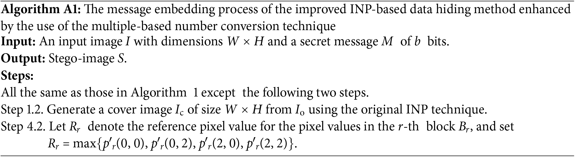
(b) An Example of Applying Algorithm A1 for Message Embedding
An example of applying Algorithm A1 for embedding a given message into a cover image Ic obtained in Stage I of the algorithm, is illustrated in Fig. A1, with the corresponding intermediate results also displayed. The image Ic is divided into two overlapping 3 × 3 blocks for data embedding in Step 1.3 of the algorithm. Assume the message to be embedded is a binary string M = 10001010010011001010012 of the length b = 22. This bit string is first converted into a large integer m = 226589710 as done by Step 2 of the algorithm. Also, a is set to be 1 in Step 3.
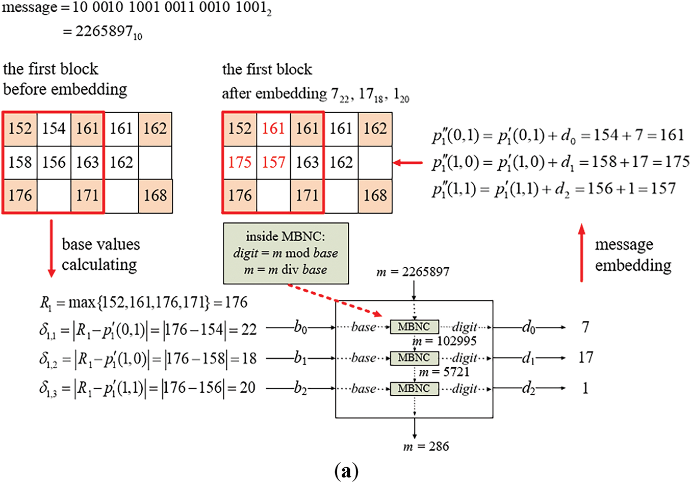
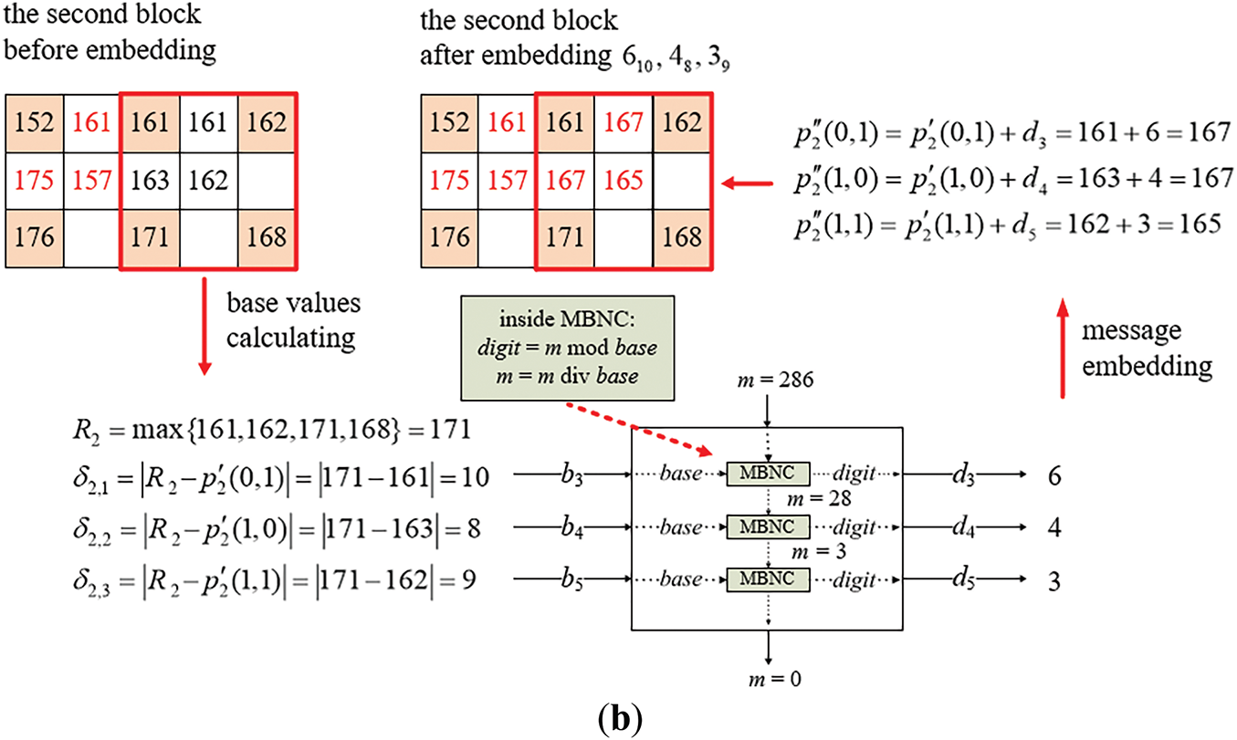
Figure A1: Illustration of an example of applying Algorithm A1 to embed a binary message string into a two-block cover image. (a) The embedding process for the first block. (b) The embedding process for the second block
(i) Embedding Message Bits into the First Block
In the beginning, the base values are computed from the pixel values of the cover image Ic as shown on the left side of Fig. A1a. Specifically, with the non-pivot pixel values p′1(0, 1), p′1(1, 0), and p′1(1, 1) which are 154, 158, and 156, respectively, and the reference pixel value R1 = max{152, 161, 176, 171} = 176, between R1 and the values of the non-pivot pixels are calculated to be δ1,1 = |176 − 154| = 22, δ1,2 = |176 − 158| = 18, and δ1,3 = |176 − 156| = 20, all of which are larger than 2, they are appropriate, as required by Step 4.3.2, to be used as base values b0 = 22, b1 = 18, and b2 = 20 for embedding the corresponding digits of the multiple-based number.
Next, as described in Steps 4.3.4 and 4.3.6, the large integer m (used to generate digits to be embedded) is divided sequentially by the corresponding base values b0, b1, and b2 using successive integer divisions. The serial remainders obtained from these divisions are used as the digit values d0, d1, and d2 of the desired multiple-based number. Finally, these digit values are embedded into p′1(0, 1), p′1(1, 0), and p′1(1, 1), respectively, as described by Step 4.3.5. More details of this message embedding process is presented in the following.
1. According to d0 = m mod b0, the first digit d0 in the multiple-based number is calculated as 2,265,897 mod 22 = 7 which is embedded into p′1(0, 1) by adding d0 to p′1(0, 1) to obtain the new pixel value p″1(0, 1) = 154 + 7 = 161.
2. The value of m is updated to be m div b0 = 2,265,897 div 22 = 102,995, the product value a of the sequentially-created bases is updated to be a × b0 = 1 × 22 = 22, and the result 22 is checked to be smaller than 2b = 222 = 4,1943,04, as done in Steps 4.3.6–4.3.8, meaning that more message bit embedding may be continued.
3. According to d1 = m mod b1, the second digit d1 = 102,995 mod 18 = 17, and embedded into p′1(1, 0) by adding d1 to p′1(1, 0), yielding the new pixel value p″1(1, 0) = 158 + 17 = 175.
4. The value of m is updated to be m div b1 = 102,995 div 18 = 5,721, and that of a to be a × b1 = 22 × 18 = 396 with 396 < 222 = 4,194,304 being checked, meaning that more message-bit embedding may be continued.
5. According to d2 = m mod b2, the third digit d2 = 5,721 mod 20 = 1 which is then embedded into p′1(1, 1) by adding d2 to p′1(1, 1) to obtain the new pixel value p″1(1, 1) = 156 + 1 = 157.
6. The value of m is updated to be m div b2 = 5,721 div 20 = 286, and that of a to be a × b2 = 396 × 20 = 7,920 < 222 = 4,194,304, meaning that more embedding may be continued by processing the second block as shown in Fig. A1b.
At the end of embedding in the first block, the embedded digits are d0(b0), d1(b1), and d2(b2), namely 722, 1718, and 120, respectively, with the values of m and a being 28610 and 7,920.
(ii) Embedding Message Bits in the Second Block
The embedding process is then performed similarly on the second block of the cover image Ic as illustrated in Fig. A1b. The non-pivot pixel values used for embedding in this block are p′2(0, 1), p′2(1, 0), and p′2(1, 1), which are 161, 163, and 162, respectively, while the reference pixel value R2 = max{161, 162, 171, 168} = 171. The absolute differences are calculated to be δ2,1 = |171 − 161| = 10, δ2,2 = |171 − 163| = 8, and δ2,3 = |171 − 162| = 9, all of which are larger than 2, they are appropriate, as required by Step 4.3.2, to be used as base values b3 = 10, b4 = 8, and b5 = 9. Three digits d3, d4, and d5 obtained as the remainders resulting from dividing m by b3, b4, and b4 successively are then embedded into p′2(0, 1), p′2(1, 0), and p′2(1, 1), respectively. The details are described in the following, as a continuation of those of processing the first block.
7. According to d3 = m mod b3, the fourth digit d3 is computed to be 286 mod 10 = 6, which is embedded into p′2(0, 1) by adding d3 to p′2(0, 1) to obtain the new pixel value p″2(0, 1) = 161 + 6 = 167.
8. The value of m is updated to be m div b3 = 286 div 10 = 28, and that of a to be a × b3 = 7,920 × 10 = 79,200 < 222 = 4,194,304, meaning that more message bit embedding may be continued.
9. According to d4 = m mod b4, the fifth digit d4 is computed to be 28 mod 8 = 4, which is embedded into p′2(1, 0) by adding d4 to p′2(1, 0) to obtain the new pixel value p″2(1, 0) = 163 + 4 = 167.
10. The value of m is updated to be m div b4 = 28 div 8 = 3, and that of a to be a × b4 = 79,200 × 8 = 633,600 < 222 = 4,194,304, meaning that more message bit embedding may be continued.
11. According to d5 = m mod b5, the sixth digit d5 is computed to be 3 mod 9 = 3, which is then embedded into p′2(1, 1) by adding d5 to p′2(1, 1) to obtain the new pixel value p″2(1, 1) = 162 + 3 = 165.
12. The value of m is updated to be m div b5 = 3 div 9 = 0, and that of a to be a × b5 = 633,600 × 9 = 5,702,400 ≥ 222 = 4,194,304, indicating that the 22-bit secret message has been fully embedded and the algorithm is stopped according to Step 4.3.8.
As a result, the digits embedded in the second block are d3(b3), d4(b4), and d5(b5), namely 610, 48, and 39. Consequently, the entire secret message embedded into the two blocks forms the multiple-based number 39486101201718722.
Appendix C.2 Message Extraction
The extraction algorithm of the improved INP-based data hiding method is presented below, which is a simplified version of the extraction algorithm of the improved NMI-based data hiding method (Algorithm 2).
(a) Message Extraction Algorithm (Algorithm A2)
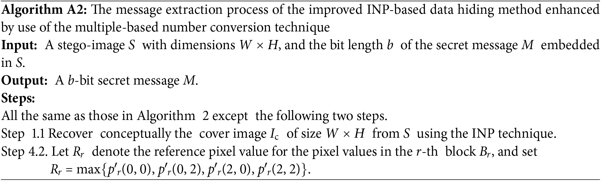
(b) An Example of Applying Algorithm A2 for Message Extraction
An example of applying Algorithm A2 for message extraction from a stego-image S obtained as illustrated in Fig. A1 is shown in Fig. A2 with computations of the computed intermediate results also shown in the figure. The process begins with conceptually recovering the cover image Ic from the stego-image S by applying the INP technique, followed by dividing both S and Ic into two overlapping 3 × 3 blocks for data extraction by Steps 1.2 and 1.4. Also, m is set to be 0 in Step 2 and a is set to be 1 in Step 3. More details of the message extraction process are described in the following.
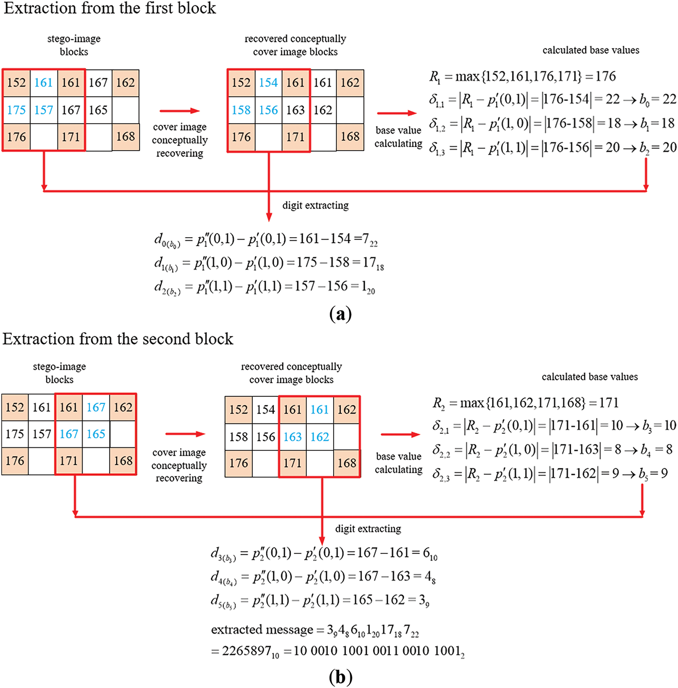
Figure A2: Illustration of an example of applying Algorithm A2 to extract a binary message string from a two-block stego-image. (a) The extraction process for the first block. (b) The extraction process for the second block
(i) Extraction Message Bits from the First Block
The base values are first recovered from the non-pivot pixel values in the first block of the conceptually-recovered cover image Ic through Steps 4.1, 4.2, and 4.3.1–4.3.3, as illustrated on the right side of Fig. A2a. Specifically, with the non-pivot pixel values p′1(0, 1), p′1(1, 0), and p′1(1, 1) being 154, 158, and 156, respectively and the reference pixel value R1 = max{152, 161, 176, 171} being 176, the absolute differences between R1 and the non-pivot pixels’ values are calculated to be δ1,1 = |176 − 154| = 22, δ1,2 = |176 − 158| = 18, and δ1,3 = |176 − 156| = 20. Since all these three differences are greater than or equal to 2, they are appropriate, as required by Step 4.3.2, to be used as the base values b0 = 22, b1 = 18, b2 = 20 for extracting the corresponding digits of the multiple-based number to be found out.
Subsequently, as performed by the operations of Step 4.3.4, the differences between the stego-image pixel values p″1(0, 1), p″1(1, 0), and p″1(1, 1) and the corresponding cover image pixel values p′1(0, 1), p′1(1, 0), and p″1(1, 1) are computed to extract the digits d0, d1, and d2 of the multiple-based number. The detailed extraction steps are described as follows.
1. According to d0 = p″1 (0, 1) − p′1(0, 1), the first digit d0 in the multiple-based number is computed to be p″1(0, 1) − p′1(0, 1) = 161 − 154 = 7.
2. The value of m is updated to be m + (d0 × a) = 0 + (7 × 1) = 7, and the product value a of sequentially-created bases to be a × b0 = 1 × 22 = 22 which is checked to be smaller than the value 2b = 222 = 4,194,304, as done in Steps 4.3.5–4.3.7, meaning that more message bit extraction may be continued.
3. According to d1 = p″1(1, 0) − p1′(1, 0), the second digit d1 is computed to be 175 − 158 = 17.
4. The value of m is updated to be m + (d1 × a) = 7 + (17 × 22) = 381, and that of a to be a × b1 = 22 × 18 = 396 < 222 = 4,194,304, meaning that more extraction may be continued.
5. According to d2 = p″1(1, 1) − p1′(1, 1), the third digit d2 is computed to be 157 − 156 = 1.
6. The value of m is updated to be m + (d2 × a) = 381 + (1 × 396) = 777 and that of a to be a × b2 = 396 × 20 = 7,920 < 222 = 4,194,304, meaning that more extraction may be continued by processing the second block as shown in Fig. A2b.
At the end of the process of extraction from the first block, the extracted digits are d0(b0), d1(b1), and d2(b2), namely 722, 1718, and 120, with the values of m and a being 777 and 7,920.
(ii) Extraction of the Message Bits from the Second Block
The extraction process is then applied in a similar manner to the second block of the stego-image S as illustrated in Fig. A2b. Additional base values of the multiple-based number are recovered from non-pivot pixel values in the second block of the recovered cover image Ic by Steps 4.1, 4.2, and 4.3.1–4.3.3, as shown at the right of Fig. A2b. Specifically, with the non-pivot pixel values p′2(0, 1), p′2(1, 0), and p′2(1, 1) which are 161, 163, and 162, respectively, and the reference pixel value R2 = max{161, 162, 171, 168} which is 171, the absolute difference values between the latter values and the former ones are calculated to be δ2,1 = |171 − 161| = 10, δ2,2 = |171 − 163| = 8, and δ2,3 = |171 − 162| = 9. Since all of which are larger than 2, they are appropriate, as required by Step 4.3.2, to be used as base values b3 = 10, b4 = 8, and b5 = 9 for extracting the corresponding digits of the desired multiple-based number. Accordingly, the difference values between the stego-image pixel values p″2(0, 1), p″2(1, 0), and p″2(1, 1) and the corresponding cover image pixel values p′2(0, 1), p′2(1, 0), and p′2(1, 1) are computed to extract respectively the digits d3, d4, and d5 of the multiple-based number. The details are described in the following, as a continuation of those of processing the first block described previously.
7. According to d3 = p″2(0, 1) − p′2(0, 1), the fourth digit d3 is computed to be 167 − 161 = 6.
8. The value of m is updated to be m + (d3 × a) = 777 + (6 × 7,920) = 48,297, and that of a to be a × b3 = 7,920 × 10 = 79,200 < 222 = 4,194,304, meaning that more extraction may be continued.
9. According to d4 = p″2(1, 0) − p′2(1, 0), the fifth digit d4 is computed to be 167−163 = 4.
10. The value of m is updated to be m + (d4 × a) = 48,297 + (4 × 79,200) = 365,097, and that of a to be a × b4 = 79,200 × 8 = 633,600 < 222 = 4,194,304, meaning that more extraction may be continued.
11. According to d5 = p″2(1, 1) − p′2(1, 1), the sixth digit d5 is computed to be 165 − 162 = 3.
12. The value of m is updated to be m + (d5 × a) = 365,097 + (3 × 633,600) = 2,265,897, and that of a to be a × b5 = 633,600 × 9 = 5,702,400 ≥ 222 = 4,194,304, indicating that the 22-bit secret message has been fully extracted and the algorithm is stopped according to Step 4.3.7.
As a result, the digits extracted from the second block are d3(b3), d4(b4), and d5(b5), namely 610, 48, and 39. Consequently, the entire secret message extracted from the two blocks forms the multiple-based number 39486101201718722. Finally, the value of m = 2,265,897 is converted to be a bit string M = 10001010010011001010012 of the length b = 22 as the extracted message.
Appendix D Improving the NIE-Based Data Hiding Method by Multiple-Based Number Conversion
In this section, the proposed enhancement of the NIE-based data hiding method using multiple-based number conversion is presented, followed by the detailed descriptions of the embedding and extraction processes of the improved method.
Appendix D.1 Message Embedding: The message embedding process of the improved NIE-based data hiding method starts by generating a cover image through the interpolation scheme used in the original NIE-based data hiding method. Next, the secret message to be embedded is converted into a large integer m for subsequent processing. Also, for each 3 × 3 block Br of the cover image, the upper-left corner of Br is taken to be a reference pixel and serves as the basis for subsequent calculations, whose value is denoted as Rr. Then, three difference values di1, di2, and di3 (with i = 1, 2, 3) are set to be di1 = |Rr − p′r,i|, di2 = 255 − p′r,i, di3 = 2U for each of the three pivot pixels with values denoted by p′r,i, where U is a preset value constrained by 1 ≤ U ≤ 8. The smallest of the three difference values, min(di1, di2, di3), is calculated as the final difference value δr,i. If δr,i ≥ 2, it is taken as a base. Subsequently, successive integer divisions of the large integer m by the found bases are conducted with the remainders taken as the digits of a multiple-based number. Finally, these digit values are embedded into the newly generated non-pivot pixels associated with the corresponding base values, thus completing the embedding process.
The message embedding algorithm of the improved NIE-based data hiding method is presented below, which is a simplified version of the embedding algorithm of the improved NMI-based data hiding method described by Algorithm 1, followed by a step-by-step presentation of an application example of the algorithm.
(a) Message Embedding Algorithm (Algorithm A3)
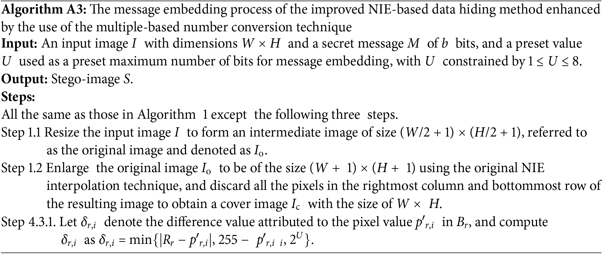
(b) An Example of Applying Algorithm A3 for Message Embedding
An illustration of Algorithm A3 (for U = 4) being applied to embed a given message into a cover image Ic obtained in Stage I of the algorithm is illustrated in Fig. A3 with computed intermediate results also shown in the figure. The image Ic is divided into two overlapping 3 × 3 blocks for data embedding. Assume that the message to be embedded is a binary string M = 1111010100001100001112 of the length b = 21. This bit string is firstly converted into a large integer m = 200743110 as done by Step 2 of the algorithm. Also, a is set to be 1 in Step 3.
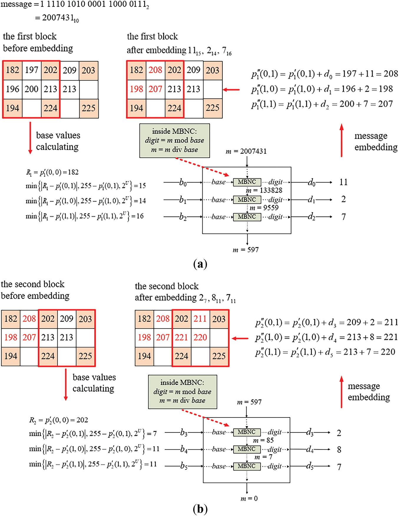
Figure A3: Illustration of an example of applying Algorithm A3 to embed a binary message string into a two-block cover image. (a) The embedding process for the first block. (b) The embedding process for the second block
(i) Embedding Message Bits into the First Block
At the start, the base values are computed from the pixel values of the cover image Ic as shown at the left of Fig. A3a. Specifically, with the non-pivot pixel values p′1(0, 1), p′1(1, 0), and p′1(1, 1) which are 197, 196, and 200, respectively and the reference pixel value R1 = p′1(0, 0) = 182. The difference values attributed to the pixel values p′1,1, p′1,2, and p′1,3 are calculated to be δ1,1 = min{|182 − 197|, 255 − 197, 16} = 15, δ1,2 = min{|182 − 196|, 255 − 196, 16} = 14, and δ1,3 = min{|182 − 200|, 255 − 200, 16} = 16, respectively, all of which are larger than 2, they are appropriate, as required by Step 4.3.2, to be used as base values b0 = 15, b1 = 14, and b2 = 16 for embedding the corresponding digits of the multiple-based number.
Following this, the large integer m, used to generate digits for embedding, is sequentially divided by the corresponding base values b0, b1, and b2 using the successive integer divisions described in Steps 4.3.4 and 4.3.6.
The serial remainders obtained from these divisions are used as the digit values d0, d1, and d2 of the desired multiple-based number. Finally, these digit values are embedded into p′1(0, 1), p′1(1, 0), and p′1(1, 1), respectively, as described by Step 4.3.5. More details of this message embedding process is presented in the following.
1. By d0 = m mod b0, the first digit d0 in the multiple-based number is computed to be 2,007,431 mod 15 = 11 which is embedded into p′1(0, 1) by adding d0 to p′1(0, 1) to obtain the new pixel value p″1(0, 1) = 197 + 11 = 208.
2. The value of m is updated to be m div b0 = 2,007,431 div 15 = 133,828, the product value a of the sequentially-created bases is updated to be a × b0 = 1 × 15 = 15, and the result 15 is checked to be smaller than 2b = 221 = 2,097,152, as done in Steps 4.3.6–4.3.8, meaning that more message bit embedding may be continued.
3. By d1 = m mod b1, the second digit d1 is computed to be 133,828 mod 14 = 2 which is embedded into p′1(1, 0) by adding d1 to p′1(1, 0) to obtain the new pixel value p″1(1, 0) = 196 + 2 = 198.
4. The value of m is updated to be m div b1 = 133,828 div 14 = 9,559, and that of a to be a × b1 = 15 × 14 = 210 with 210 < 221 = 2,097,152 being checked, meaning that more message-bit embedding may be continued.
5. By d2 = m mod b2, the third digit d2 is computed to be 9,559 mod 16 = 7 which is then embedded into p′1(1, 1) by adding d2 to p′1(1, 1) to obtain the new pixel value p″1(1, 1) = 200 + 7 = 207.
6. The value of m is updated to be m div b2 = 9,559 div 16 = 597, and that of a to be a × b2 = 210 × 16 = 3,360 < 221 = 2,097,152, meaning that more embedding may be continued by processing the second block as shown in Fig. A3b.
At the end of embedding in the first block, the embedded digits are d0(b0), d1(b1), and d2(b2), namely 1115, 214, and 716, respectively, with the values of m and a being 59710 and 3,360.
(ii) Embedding Message Bits in the Second Block
The embedding process is then applied in the same manner to the second block of the cover image Ic as illustrated in Fig. A3b. The non-pivot pixel values used for embedding in this block are p′2(0, 1), p′2(1, 0), and p′2(1, 1), which are 209, 213, and 213, respectively, while the reference pixel value R2 = p′2(0, 0) = 202. The difference values attributed to the pixel values p′2,1, p′2,2, and p′2,3 are calculated to be δ2,1 = min{|202 − 209|, 255 − 209, 16} = 7, δ2,2 = min{|202 − 213|, 255 − 213, 16} = 11, and δ2,3 = min{|202 − 213|, 255 − 213, 16} = 11, respectively, all of which are larger than 2, they are appropriate, as required by Step 4.3.2, to be used as base values b3 = 7, b4 = 11, and b5 = 11. Three digits d3, d4, and d5 obtained as the remainders resulting from dividing m by b3, b4, and b4 successively are then embedded into p′2(0, 1), p′2(1, 0), and p′2(1, 1), respectively. The details are described in the following, as a continuation of those of processing the first block.
7. By d3 = m mod b3, the fourth digit d3 is computed to be 597 mod 7 = 2, which is embedded into p′2(0, 1) by adding d3 to p′2(0, 1) to obtain the new pixel value p″2(0, 1) = 209 + 2 = 211.
8. The value of m is updated to be m div b3 = 597 div 7 = 85, and that of a to be a × b3 = 3,360 × 7 = 23,520 < 221 = 2,097,152, meaning that more message bit embedding may be continued.
9. By d4 = m mod b4, the fifth digit d4 is computed to be 85 mod 11 = 8, which is embedded into p′2(1, 0) by adding d4 to p′2(1, 0) to obtain the new pixel value p″2(1, 0) = 213 + 8 = 221.
10. The value of m is updated to be m div b4 = 85 div 11 = 7, and that of a to be a × b4 = 23,520 × 11 = 258,720 < 221 = 2,097,152, meaning that more message bit embedding may be continued.
11. By d5 = m mod b5, the sixth digit d5 is computed to be 7 mod 11 = 7, which is then embedded into p′2(1, 1) by adding d5 to p′2(1, 1) to obtain the new pixel value p″2(1, 1) = 213 + 7 = 220.
12. The value of m is updated to be m div b5 = 7 div 11 = 0, and that of a to be a × b5 = 258,720 × 11 = 2,845,920 ≥ 221 = 2,097,152, indicating that the 21-bit secret message has been fully embedded and the algorithm is stopped according to Step 4.3.8.
As a result, the digits embedded in the second block are d3(b3), d4(b4), and d5(b5), namely 27, 811, and 711. Consequently, the entire secret message embedded into the two blocks forms the multiple-based number 711811277162141115.
Appendix D.2 Message Extraction: The message extraction algorithm of the improved NIE-based data hiding method is presented below, which is a simplified version of the extraction algorithm of the improved NMI-based data hiding method (Algorithm 2).
(a) Message Extraction Algorithm (Algorithm A4)
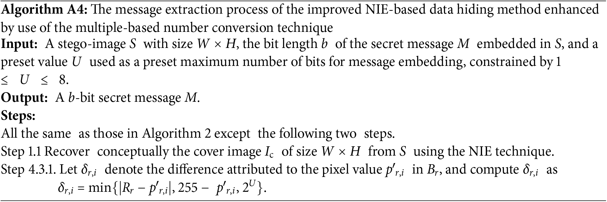
(b) An Example of Applying Algorithm A4 for Message extraction
An example of applying Algorithm A4 (for U = 4) for message extraction from a stego-image S is yielded by Algorithm A3 as illustrated in Fig. A3 is shown in Fig. A4, where the stego-image S is obtained by applying Algorithm A4 as illustrated in Fig. A4 with the computations of the intermediate results being described in the following. The process begins by conceptually recovering the cover image Ic from the stego-image S using the NIE technique, as carried out by Step 1.1 of Algorithm A4. Both S and Ic are divided into two 3 × 3 blocks for data extraction by Steps 1.2 and 1.4. Also, m is set to be 0 in Step 2 and a is set to be 1 in Step 3. More details of the message extraction process are described in the following.
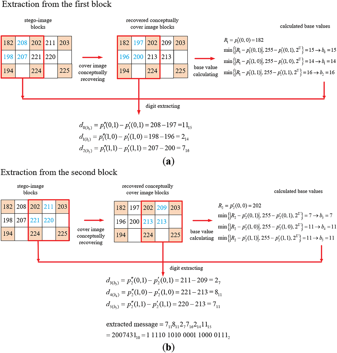
Figure A4: Illustration of an example of applying Algorithm A4 to extract a binary message string from a two-block stego-image. (a) The extraction process for the first block. (b) The extraction process for the second block
(i) Extraction Message Bits from the First Block
The base values are initially recovered from the non-pivot pixel values in the first block of the conceptually-recovered cover image Ic by Steps 4.1, 4.2, and 4.3.1–4.3.3, as illustrated at the right of Fig. A4a. Specifically, with the non-pivot pixel values p′1(0, 1), p′1(1, 0), and p′1(1, 1) being 197, 196, and 200, respectively and the reference pixel value R1 = p′1(0, 0) = 182 being 176. The difference values attributed to the pixel values p′1,1, p′1,2, and p′1,3 are calculated to be δ1,1 = min{|182 − 197|, 255 − 197, 16} = 15, δ1,2 = min{|182 − 196|, 255 − 196, 16} = 14, and δ1,3 = min{|182 − 200|, 255 − 200, 16} = 16, respectively. Since all these three differences are greater than or equal to 2, they are appropriate, as required by Step 4.3.2, to be used as the base values b0 = 15, b1 = 14, b2 = 16 for extracting the corresponding digits of the multiple-based number to be found out.
As performed by the operations in Step 4.3.4, the differences between the stego-image pixel values p″1(0, 1), p″1(1, 0), and p″1(1, 1) as well as the corresponding cover image pixel values p′1(0, 1), p′1(1, 0), and p″1(1, 1) are computed to extract the digits d0, d1, and d2 of the multiple-based number. The detailed extraction steps are described as follows.
1. By d0 = p″1 (0, 1) − p′1(0, 1), the first digit d0 in the multiple-based number is computed to be p″1(0, 1) − p′1(0, 1) = 208−197 = 11.
2. The value of m is updated to be m + (d0 × a) = 0 + (11 × 1) = 11, and the product value a of sequentially-created bases to be a × b0 = 1 × 15 = 15 which is checked to be smaller than the value 2b = 221 = 2,097,152, as done in Steps 4.3.5–4.3.7, meaning that more message bit extraction may be continued.
3. By d1 = p″1(1, 0) − p1′(1, 0), the second digit d1 is computed to be 198−196 = 2.
4. The value of m is updated to be m + (d1 × a) = 11 + (2 × 15) = 41, and that of a to be a × b1 = 15 × 14 = 210 < 221 = 2,097,152, meaning that more extraction may be continued.
5. By d2 = p″1(1, 1) − p1′(1, 1), the third digit d2 is computed to be 207−200 = 7.
6. The value of m is updated to be m + (d2 × a) = 41 + (7 × 210) = 1,511 and that of a to be a × b2 = 210 × 16 = 3,360 < 221 = 2,097,152, meaning that more extraction may be continued by processing the second block as shown in Fig. A4b.
At the end of the process of extraction from the first block, the extracted digits are d0(b0), d1(b1), and d2(b2), namely 1115, 214, and 716, with the value of m and a being 1,511 and 3,360.
(ii) Extraction of the Message Bits from the Second Block
The extraction process is then performed similarly on the second block of the stego-image S as illustrated in Fig. A4b. Additional base values of the multiple-based number are recovered from non-pivot pixel values in the second block of the recovered cover image Ic by Steps 4.1, 4.2, and 4.3.1–4.3.3, as shown at the right of Fig. A4b. Specifically, with the non-pivot pixel values p′2(0, 1), p′2(1, 0), and p′2(1, 1) which are 209, 213, and 213, respectively, and the reference pixel value R2 = p′2(0, 0) = 202. The difference values attributed to the pixel values p′2,1, p′2,2, and p′2,3 are calculated to be δ2,1 = min{|202 − 209|, 255 − 209, 16} = 7, δ2,2 = min{|202 − 213|, 255 − 213, 16} = 11, and δ2,3 = min{|202 − 213|, 255 − 213, 16} = 11, respectively. Since all of which are larger than 2, they are appropriate, as required by Step 4.3.2, to be used as base values b3 = 7, b4 = 11, and b5 = 11 for extracting the corresponding digits of the desired multiple-based number. Accordingly, the difference values between the stego-image pixel values p″2(0, 1), p″2(1, 0), and p″2(1, 1) as well as the corresponding cover image pixel values p′2(0, 1), p′2(1, 0), and p′2(1, 1) are computed to extract respectively the digits d3, d4, and d5 of the multiple-based number. The details are described in the following, as a continuation of those of processing the first block described previously.
7. By d3 = p″2(0, 1) − p′2(0, 1), the fourth digit d3 is computed to be 211 − 209 = 2.
8. The value of m is updated to be m + (d3 × a) = 1,511 + (2 × 3,360) = 8,231, and that of a to be a × b3 = 3,360 × 7 = 23,520 < 221 = 2,097,152, meaning that more extraction may be continued.
9. By d4 = p″2(1, 0) − p′2(1, 0), the fifth digit d4 is computed to be 221 − 213 = 8.
10. The value of m is updated to be m + (d4 × a) = 8,231 + (8 × 23,520) = 196,391, and that of a to be a × b4 = 23,520 × 11 = 258,720 < 221 = 2,097,152, meaning that more extraction may be continued.
11. By d5 = p″2(1, 1) − p′2(1, 1), the sixth digit d5 is computed to be 220 − 213 = 7.
12. The value of m is updated to be m + (d5 × a) = 196,391 + (7 × 258,720) = 2,007,431, and that of a to be a × b5 = 258,720 × 11 = 2,845,920 ≥ 221 = 2,097,152, indicating that the 21-bit secret message has been fully extracted and the algorithm is stopped according to Step 4.3.7.
As a result, the digits extracted from the second block are d3(b3), d4(b4), and d5(b5), namely 27, 811, and 711. Consequently, the entire secret message extracted from the two blocks forms the multiple-based number 711811277162141115. The value of m = 2,007,431 is finally converted to be a bit string M = 1111010100001100001112 of the length b = 21 as the extracted message.
References
1. Cox IJ, Miller ML, Bloom JA, Fridrich J, Kalker T. Digital watermarking and steganography. 2nd ed. Burlington, MA, USA: Morgan Kaufmann; 2008. 593 p. doi:10.1016/B978-0-12-372585-1.X5001-3. [Google Scholar] [CrossRef]
2. Li Z, Wu Y, Mazroa AA, Jiang D, Wu J, Zhu X. Image hiding with high robustness based on dynamic region attention in the wavelet domain. Comput Model Eng Sci. 2024;141(1):847–69. doi:10.32604/cmes.2024.051762. [Google Scholar] [CrossRef]
3. Khadse DB, Swain G. Data hiding and integrity verification based on quotient value differencing and merkle tree. Arab J Sci Eng. 2023;48(2):1793–805. doi:10.1007/s13369-022-06961-9. [Google Scholar] [CrossRef]
4. Kosuru SNVJD, Pradhan A, Basith KA, Sonar R, Swain G. Digital image steganography with error correction on extracted data. IEEE Access. 2023;11:80945–57. doi:10.1109/ACCESS.2023.3300918. [Google Scholar] [CrossRef]
5. Zhao P, Zhong Q, Chen J, Wang X, Qin Z, Zhou E. A linked list encryption scheme for image steganography without embedding. Comput Model Eng Sci. 2024;141(1):331–52. doi:10.32604/cmes.2024.050148. [Google Scholar] [CrossRef]
6. Wang RZ, Lin CF, Lin JC. Image hiding by optimal LSB substitution and genetic algorithm. Pattern Recognit. 2001;34(3):671–83. doi:10.1016/S0031-3203(00)00015-7. [Google Scholar] [CrossRef]
7. Tian J. Reversible watermarking using a difference expansion. IEEE Trans Circuits Syst Video Technol. 2003;13(8):890–6. doi:10.1109/TCSVT.2003.815962. [Google Scholar] [CrossRef]
8. Ding W, Zhang H, Reulke R, Wang Y. Reversible image data hiding based on scalable difference expansion. Pattern Recognit Lett. 2022;159(4):116–24. doi:10.1016/j.patrec.2022.05.014. [Google Scholar] [CrossRef]
9. Ni Z, Shi YQ, Ansari N, Su W. Reversible data hiding. IEEE Trans Circuits Syst Video Technol. 2006;16(3):354–62. doi:10.1109/TCSVT.2006.869964. [Google Scholar] [CrossRef]
10. Jia Y, Yin Z, Zhang X, Luo Y. Reversible data hiding based on reducing invalid shifting of pixels in histogram shifting. Signal Process. 2019;163:238–46. doi:10.1016/j.sigpro.2019.05.020. [Google Scholar] [CrossRef]
11. Thodi DM, Rodríguez JJ. Expansion embedding techniques for reversible watermarking. IEEE Trans Image Process. 2007;16(3):721–30. doi:10.1109/TIP.2006.891046. [Google Scholar] [PubMed] [CrossRef]
12. Li X, Li X, Hu S, Zhao Y. Steganography-enhanced prediction-error expansion: a novel reversible data hiding framework. IEEE Trans Circuits Syst Video Technol. 2025;35(3):2701–11. doi:10.1109/TCSVT.2024.3495673. [Google Scholar] [CrossRef]
13. Wu DC, Tsai WH. A steganographic method for images by pixel-value differencing. Pattern Recognit Lett. 2003;24(10):1613–26. doi:10.1016/S0167-8655(02)00402-6. [Google Scholar] [CrossRef]
14. Jung KH, Yoo KY. Data hiding method using image interpolation. Comput Stand Interfaces. 2009;31(2):465–70. doi:10.1016/j.csi.2008.06.001. [Google Scholar] [CrossRef]
15. Lee CF, Huang YL. An efficient image interpolation increasing payload in reversible data hiding. Expert Syst Appl. 2012;39(8):6712–9. doi:10.1016/j.eswa.2011.12.019. [Google Scholar] [CrossRef]
16. Solak S. High embedding capacity data hiding technique based on EMSD and LSB substitution algorithms. IEEE Access. 2020;8:166513–24. doi:10.1109/ACCESS.2020.3023197. [Google Scholar] [CrossRef]
17. Wu DC, Shih ZN. Image steganography by pixel-value differencing using general quantization ranges. Comput Model Eng Sci. 2024;141(1):353–83. doi:10.32604/cmes.2024.050813. [Google Scholar] [CrossRef]
18. Wu DC, Tsai WH. Data hiding images via mult-based number convers lossy compress. IEEE Trans Consum Electron. 1998;44(4):1406–12. doi:10.1109/30.735844. [Google Scholar] [CrossRef]
19. Li X, Orchard MT. New edge-directed interpolation. IEEE Trans Image Process. 2001;10(10):1521–7. doi:10.1109/83.951537. [Google Scholar] [PubMed] [CrossRef]
20. Hou H, Andrews H. Cubic splines for image interpolation and digital filtering. IEEE Trans Acoust Speech Signal Process. 1978;26(6):508–17. doi:10.1109/TASSP.1978.1163154. [Google Scholar] [CrossRef]
21. Chang YT, Huang CT, Lee CF, Wang SJ. Image interpolating based data hiding in conjunction with pixel-shifting of histogram. J Supercomput. 2013;66(2):1093–110. doi:10.1007/s11227-013-1016-6. [Google Scholar] [CrossRef]
22. Malik A, Sikk G, Verma HK. Image interpolation based high capacity reversible data hiding scheme. Multimed Tools Appl. 2017;76(22):24107–23. doi:10.1007/s11042-016-4186-4. [Google Scholar] [CrossRef]
23. Tang M, Hu J, Song W. A high capacity image steganography using multi-layer embedding. Optik. 2014;125:3972–6. doi:10.1016/j.ijleo.2014.01.149. [Google Scholar] [CrossRef]
24. Mohammad AA, Al-Haj A, Farfoura M. An improved capacity data hiding technique based on image interpolation. Multimed Tools Appl. 2018;78(6):7181–205. doi:10.1007/s11042-018-6465-8. [Google Scholar] [CrossRef]
25. Saeid Hassan FS, Gutub A. Novel embedding secrecy within images utilizing an improved interpolation-based reversible data hiding scheme. J King Saud Univ-Comput Inf Sci. 2022;34(5):2017–30. doi:10.1016/j.jksuci.2020.07.008. [Google Scholar] [CrossRef]
26. Lu TC, Huang SR, Huang SW. Reversible hiding method for interpolation images featuring a multilayer center folding strategy. Soft Comput. 2021;25(1):161–80. doi:10.1007/s00500-020-05129-7. [Google Scholar] [CrossRef]
27. Mandal PC, Mukherjee I, Chatterji BN. High capacity reversible and secured data hiding in images using interpolation and difference expansion technique. Multimed Tools Appl. 2021;80(3):3623–44. doi:10.1007/s11042-020-09341-3. [Google Scholar] [CrossRef]
28. Fan M, Zhong S, Xiong X. Reversible data hiding method for interpolated images based on modulo operation and prediction-error expansion. IEEE Access. 2023;11(1):27290–302. doi:10.1109/ACCESS.2023.3258461. [Google Scholar] [CrossRef]
29. Wu DC, Shih ZN, Wu JH. Modified multiway pixel-value differencing methods based on general quantization ranges for image steganography. IEEE Access. 2021;10:8824–39. doi:10.1109/ACCESS.2021.3138895. [Google Scholar] [CrossRef]
30. Rosen KH. Discrete mathematics and its applications. 8th ed. New York, NY, USA: McGraw-Hill; 2019. 1118 p. [Google Scholar]
31. Wang Z, Bovik AC, Sheikh HR, Simoncelli EP. Image quality assessment: from error visibility to structural similarity. IEEE Trans Image Process. 2004;13(4):600–12. doi:10.1109/TIP.2003.819861. [Google Scholar] [PubMed] [CrossRef]
32. Fridrich J, Goljan M, Du R. Reliable detection of LSB steganography in color and grayscale images. In: Proceedings of the 2001 workshop on Multimedia and security: new challenges; 2001 Oct 5; Ottawa, ON, Canada. doi:10.1145/1232454.1232466. [Google Scholar] [CrossRef]
33. Mohammad AA. A high quality interpolation-based reversible data hiding technique using dual images. Multimed Tools Appl. 2023;82(24):36713–37. doi:10.1007/s11042-023-15092-8. [Google Scholar] [CrossRef]
34. Chen YQ, Sun WJ, Li LY, Chang CC, Wang X. An efficient general data hiding scheme based on image interpolation. J Inf Secur Appl. 2020;54:102584. doi:10.1016/j.jisa.2020.102584. [Google Scholar] [CrossRef]
35. Hu J, Li T. Reversible steganography using extended image interpolation technique. Comput Electr Eng. 2015;46(7):447–55. doi:10.1016/j.compeleceng.2015.04.014. [Google Scholar] [CrossRef]
Cite This Article
 Copyright © 2025 The Author(s). Published by Tech Science Press.
This work is licensed under a Creative Commons Attribution 4.0 International License , which permits unrestricted use, distribution, and reproduction in any medium, provided the original work is properly cited.
 Downloads
 Citation Tools