
 Submit a Paper
 Propose a Special lssue
 Open Access
ARTICLE

Improved Meshfree Moving-Kriging Formulation for Free Vibration Analysis of FGM-FGCNTRC Sandwich Shells
1 Department of Mechanical and Robotic Engineering, School of Engineering and Technology, Walailak University, Thasala, Nakhon Si Thammarat, 80160, Thailand
2 Center of Excellence for Sustainable Disaster Management, Walailak University, Nakhon Si Thammarat, 80160, Thailand
3 Department of Architectural Engineering, Sejong University, Seoul, 05006, Republic of Korea
4 Laboratoire de Recherche en Génie Civil, LRGC, Université de Biskra, Biskra, 07000, Algeria
* Corresponding Authors: Tan N. Nguyen. Email: ; Nuttawit Wattanasakulpong. Email:
# Suppakit Eiadtrong and Tan N. Nguyen are co-first authors and equally contributed to this work
Computer Modeling in Engineering & Sciences 2025, 144(3), 2819-2848. https://doi.org/10.32604/cmes.2025.069481
Received 24 June 2025; Accepted 25 August 2025; Issue published 30 September 2025
 View Full Text
 Download PDF
Abstract
An improved meshfree moving-Kriging (MK) formulation for free vibration analysis of functionally graded material-functionally graded carbon nanotube-reinforced composite (FGM-FGCNTRC) sandwich shells is first proposed in this article. The proposed sandwich structure consists of skins of FGM layers and an FGCNTRC core. This structure possesses all the advantages of FGM and FGCNTRC, including high electrical or thermal insulating properties, high fatigue resistance, good corrosion resistance, high stiffness, low density, high strength, and high aspect ratios. Such sandwich structures can be used to replace conventional FGM structures. The present formulation has been established by using an improved meshfree MK method and the first-order shear deformation shell theory (FSDT). The effective material characteristics of the FGM-skin layers and the FGCNTRC core were calculated using the rule of mixture. Key parameters and factors such as the thickness-to-radius ratio, the length-to-radius ratio, layer-thickness ratios, CNT distributions, the volume fraction of CNTs, the power-law index, and various boundary conditions were rigorously investigated. A nonlinear CNT distribution that we term FG-nX is first proposed in this work, and many new results of FGM-FGCNTRC sandwich shells have been provided.Keywords
Many new materials have been found that have contributed to developments in numerous areas of science and engineering. Functionally graded materials (FGMs) are among those proposed, and many studies have been carried out on them. An FGM is a type of composite material created by mixing two distinct material phases, such as ceramic and metal. As a result, an FGM inherits the characteristics of both material components. For example, an FGM can possess important properties, like good strength, good thermal or electrical insulating properties, or high resistance to fatigue or corrosion. Consequently, such materials are now widely used in semiconductor technologies, aerospace engineering, medical applications, nuclear reactors, etc. Numerous studies have therefore been performed to investigate the behaviors of FGM structures such as beams [1], plates [2–4], and shells [5]. Another modern material- carbon nanotubes (CNTs), which are known as “materials for the 21st century” [6], have attracted considerable attention from researchers in many fields because of their notable mechanical, thermal, and electrical characteristics [7,8]. The discovery of CNTs [9] opened a new area of materials science. Practically, CNTs are very suitable for replacing conventional reinforcements like glass fibers, steel, etc., in composite structures. This is the case because CNTs possess outstanding properties such as low density but with high stiffness, strength, and aspect ratio. A typical study of CNT structures can be found in [10]. In this study, free vibration and buckling behaviors of carbon nanotube-reinforced cross-ply laminated composite plates were obtained by using the method of discrete singular convolution and a first-order shear deformation theory. In structural engineering, sandwich structures are constructed using layers of different materials, and the resulting structures fully inherit the characteristics of each constituent material. This is very useful for improving structural performance, and many types of sandwich beams, plates, and shells have therefore been proposed and investigated. In this article, FGMs and functionally graded carbon nanotube-reinforced composite (FGCNTRC) materials were used to create sandwich shells. The proposed sandwich structure consists of skins of FGM layers and an FGCNTRC core. As mentioned above, this structure possesses all the advantages of both the FGM and the FGCNTRC material. In real-world applications, shells are widely used in mechanical, civil, and aerospace engineering. Some notable applications include the roofs of buildings and stadiums, and shells of ships, cars, submarines, airplanes, and spacecrafts. Thus, the analysis and design of FGM-FGCNTRC sandwich shells are necessary and practical. Another type of FG structure-reinforced with functionally graded graphene platelet has attracted great attention due to its outstanding advantages of being lightweight but with a high load-carrying capacity [11]. In these structures, the graphene platelets are used as reinforcements to enhance the structural stiffness. Results for the vibrations of shells reinforced with graphene platelets considering non-linearity and external load can be found in [12,13]. Results for the thermomechanical free-vibration buckling of FG graphene-reinforced doubly-curved sandwich shells can be found in [14]. Additional studies of functionally graded graphene platelet-reinforced structures should be carried out in the future.
Analytical approaches are only appropriate for problems with simple geometries, boundaries, and loads. Due to these limitations, many numerical methods have been developed for structural analyses, such as the finite element method (FEM) [15], meshfree methods [16–19], isogeometric analysis [20–22], the smoothed FEM [23], etc. In addition, many FEM-based software programs have been successfully developed, such as Abaqus, Sap2000, Ansys, etc. Many meshfree methods have also been proposed, such as the element-free Galerkin method [16], the reproducing kernel particle method [24], the meshless local Petrov-Galerkin method [25], etc. Most of the meshfree methods have a similar limitation that their interpolation functions do not satisfy the Kronecker-delta property. Essential boundary conditions, thus, can not be straightforwardly imposed as in the FEM. Accordingly, several correction techniques for boundaries have been proposed and developed, including Lagrange multipliers [26], penalty methods [27], or a combination with the FEM [28]. Interestingly, the moving-Kriging (MK) interpolation function naturally satisfies the Kronecker-delta property. The meshfree MK method was first proposed to solve the one-dimensional steady-state heat conduction problem [29]. Further developments of this method can be found in [30] for one- and two-dimensional elasticity problems, thin plates [31], shells [32], piezoelectric structures [33], and laminated composite structures [34]. As shown in [29], the accuracy of the MK solutions strongly depends on the quality of the MK interpolation, which is affected by the choice of the correlation parameter
As mentioned earlier, sandwich structures possess some outstanding advantages, and numerous studies on the behaviors of sandwich shells made from FGM or FGCNTRC materials have been performed. Typical studies include analyses of shells with an FGM core and two isotropic skins [38,39], conical FGM sandwich shells [40], truncated conical FGM sandwich shells reinforced with FGM stiffeners [41], a structure with a soft viscoelastic core and FGM layers [42], cylindrical FGM sandwich shells reinforced by FGM stiffeners [43], cylindrical FGM sandwich shells reinforced using periodic eccentric ring stiffeners [44], shells with FGCNT face sheets and an isotropic core [45], the nonlinear stability of sandwich shells consisting of a porous FGM and CNT-reinforced composite layers [46], thermal vibrations of shells made of a sandwich of CNTRC sheets on both sides of a porous FG core [47], and conical sandwich shells with FG face sheets and a FG porous core [48]. In this article, we propose sandwich shells consisting of a skin of FGM layers and an FGCNTRC core. The improved MK meshfree method was first developed for modeling curved structures like shells. In addition, an improved meshfree MK formulation for free vibration analysis of FGM-FGCNTRC sandwich shells is first proposed. A nonlinear CNT distribution that we term FG-nX is proposed, and many new results of FGM-FGCNTRC sandwich shells are provided. In this paper, we investigate two types of boundaries, which are simply supported and clamped boundaries. In the case that some structures are connected by bolts or complex boundaries, the necessary information can be found in [49]. FGM-FGCNTRC sandwich shells can be used in semiconductor technologies, aerospace engineering, nuclear reactors, airplanes, spacecrafts, etc. Frequencies and vibrational mode shapes of these applications can be accurately predicted via the proposed technique in this study.
2 First-Order Shear Deformation Theory for FGM-FGCNTRC Sandwich Shells
2.1 Functionally Graded Carbon Nanotube-Reinforced Composite Materials
Fig. 1 shows five types of CNT distributions. UD is the uniform distribution. FG-V, FG-O, and FG-X are three types of linear CNT distributions. For the FG-O distribution, CNTs are enriched at the mid-surface. The top surface is CNT-rich in the case of FG-V distribution, and CNTs are enriched near both the top and bottom surfaces in the case of FG-X distribution. In this article, a nonlinear CNT distribution that we term FG-nX is proposed to enhance the stiffness of FGCNTRC structures. Similar to FG-X, FG-nX is CNT-rich near the top and bottom surfaces, but it is nonlinear through the structural thickness. Fig. 2 shows the FG-nX distribution along the thickness. The volume fraction of CNTs
where
where
where the volume fraction of the matrix is
where Poisson’s ratios are
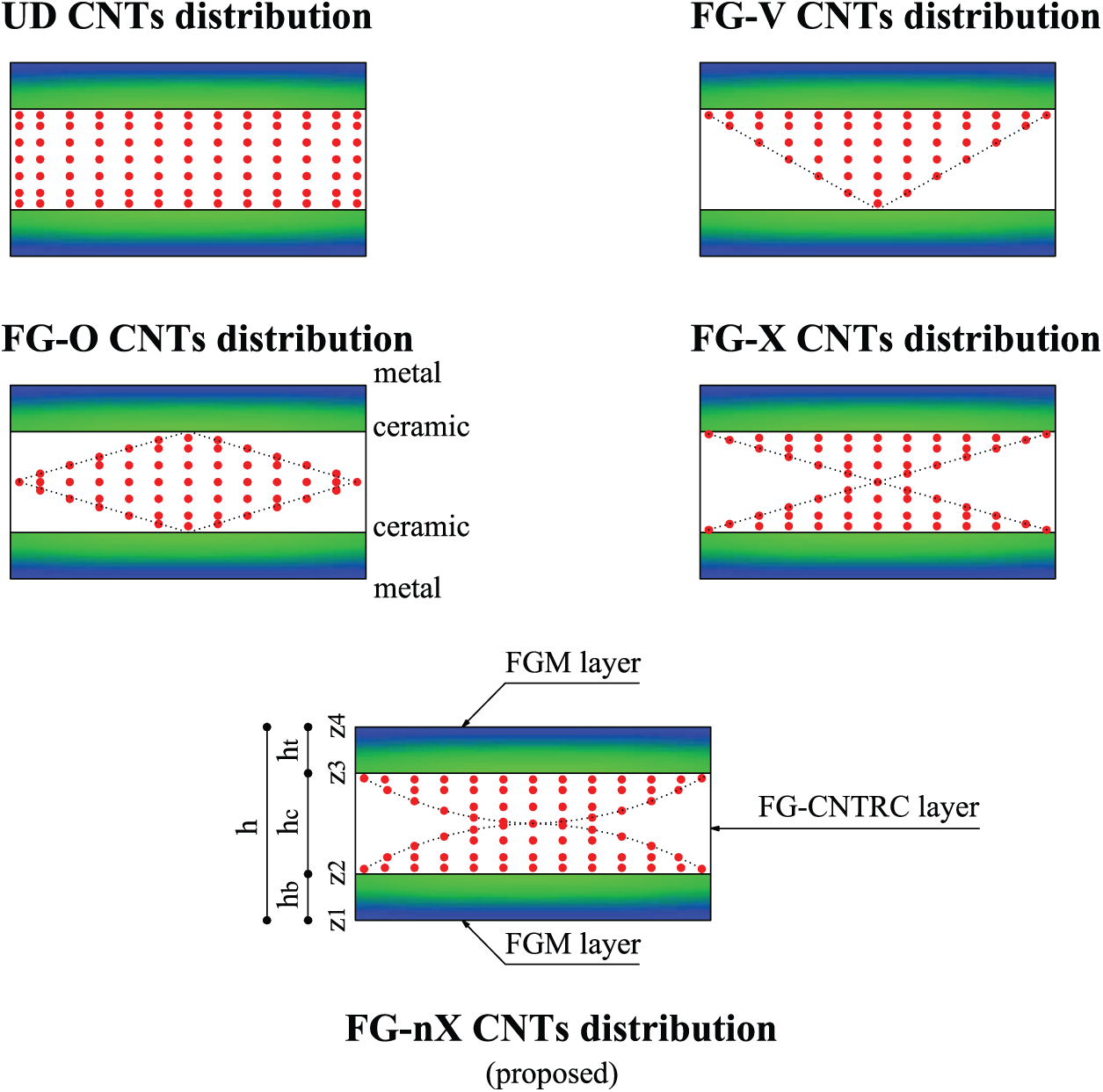
Figure 1: Constitution of an FGM-FGCNTRC sandwich structure
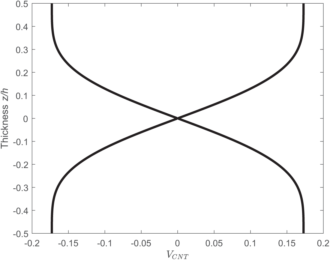
Figure 2: FG-nX distribution (proposed) along the thickness with
2.2 Functionally Graded Materials
An FGM is a composite material that consists of two distinct material phases which are ceramic and metal. Thus, an FGM fully inherits the mechanical characteristics of these two materials. The volume fractions of the material phases are determined as in [2]
where
here,
2.3 FGM-FGCNTRC Sandwich Shells
Fig. 1 shows an FGM-FGCNTRC sandwich structure with five types of CNT distributions. It consists of two FGM-skin layers and one FGCNTRC core. For the two FGM-skin layers, the metallic component is enriched at the surfaces
where
2.4 Free Vibration Analysis of FGM-FGCNTRC Sandwich Shells Using First-Order Shear Deformation Shell Theory
We consider a doubly-curved shell with the geometric characteristics shown in Figs. 3 and 4. In these figures,
and
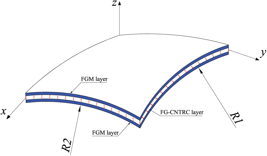
Figure 3: A doubly-curved FGM-FGCNTRC sandwich shell
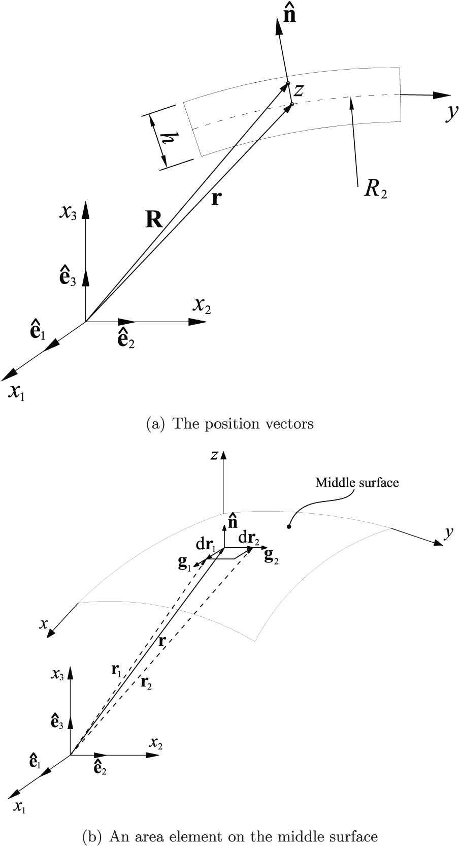
Figure 4: Geometric properties of a doubly-curved FGM-FGCNTRC sandwich shell
The linear strains written in the curvilinear coordinate system are as follows [59,60] for the in-plane strains
and for the shear strains
where
and
where
where
The constitutive equation is written based on Hooke’s law as follows [59]:
and
A Galerkin weak form derived from the motion equations for free vibration analysis is expressed as follows
where
and the shear correction factor
3 The FGM-FGCNTRC Sandwich Shell Formulation Using the Meshfree MK Method and FSDT
3.1 Improved Meshfree MK Method
We consider a domain
where
in which,
where
and
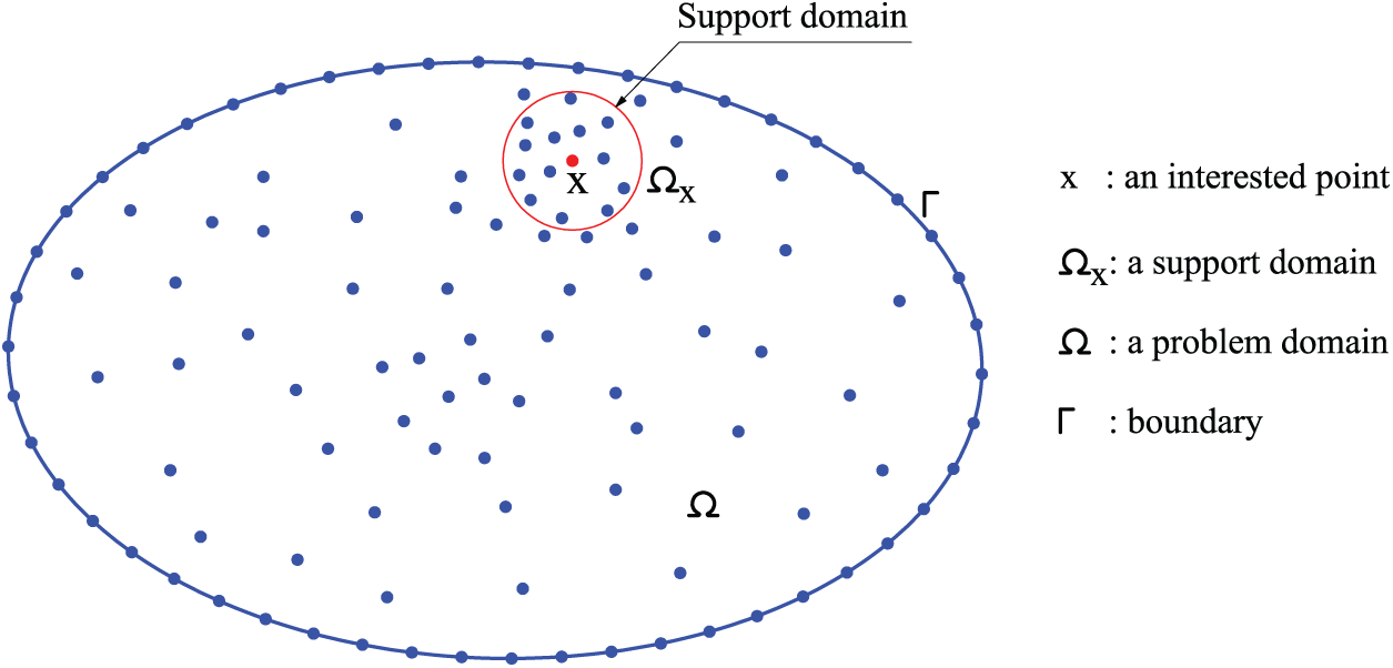
Figure 5: Discretization and support domain of a 2D problem utilizing the meshless moving-Kriging method
The MK approximation also can be re-expressed in another form as follows [35]
where
where the first- and second-order derivatives of the MK shape functions are given by
An improved meshfree MK method was proposed in [35] to ensure that the MK solutions remain stable and accurate. This improved method uses a quartic-spline correlation function to establish the MK shape functions as
where
The MK shape functions satisfy the Kronecker-delta property. Thus, the essential boundary conditions are simply and straightforwardly imposed as in the FEM. Notably, the main computational procedures of the improved meshfree MK method and the FEM are the same. In meshfree methods, a support domain is utilized to determine a set of nodes that are used for constructing the shape functions. In this article, the support domain with a circular shape as shown in Fig. 5 is utilized. The radius of this circle is determined as follows:
here,
3.2 The FGM-FGCNTRC Sandwich Shell Formulation Using the Meshfree MK Method
The displacement field u of shells can be approximated using the MK interpolation functions as follows
where
where
Eq. (38) is inserted into Eq. (19), we obtain the approximate displacement vectors as
where
Finally, by using Eqs. (39) and (41) in Eq. (24), the discretized system of equations for free vibration analysis of FGM-FGCNTRC sandwich shells based on MK meshfree method and FSDT is achieved as
where K and M are, respectively, the global stiffness and mass matrices as follows
For the FGCNTRC core, the matrix material is Poly methyl methacrylate (PMMA) [61] and the reinforcements are the armchair
•
•
•
It is assumed that
• The matrix material
• The reinforcement material
For the FGM skins, Al and
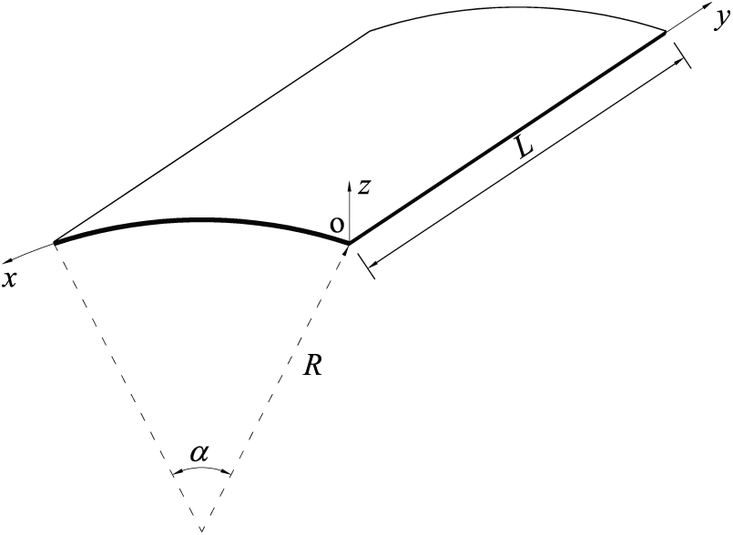
Figure 6: Geometry of a cylindrical shell
• Simply supported (S)
• Clamped (C)
In this article, boundary conditions were enforced as in the standard FEM. A mesh of 27 × 27 nodes was used for all problems, and numerical integration was performed utilizing 4 × 4 Gaussian points per each background structure cell. The computational meshes for cylindrical, spherical, and hyperbolic parabolic shells are shown in Fig. 7. Notably, the two key parameters investigated in section Parameter study are defined as the thickness-to-radius ratio (
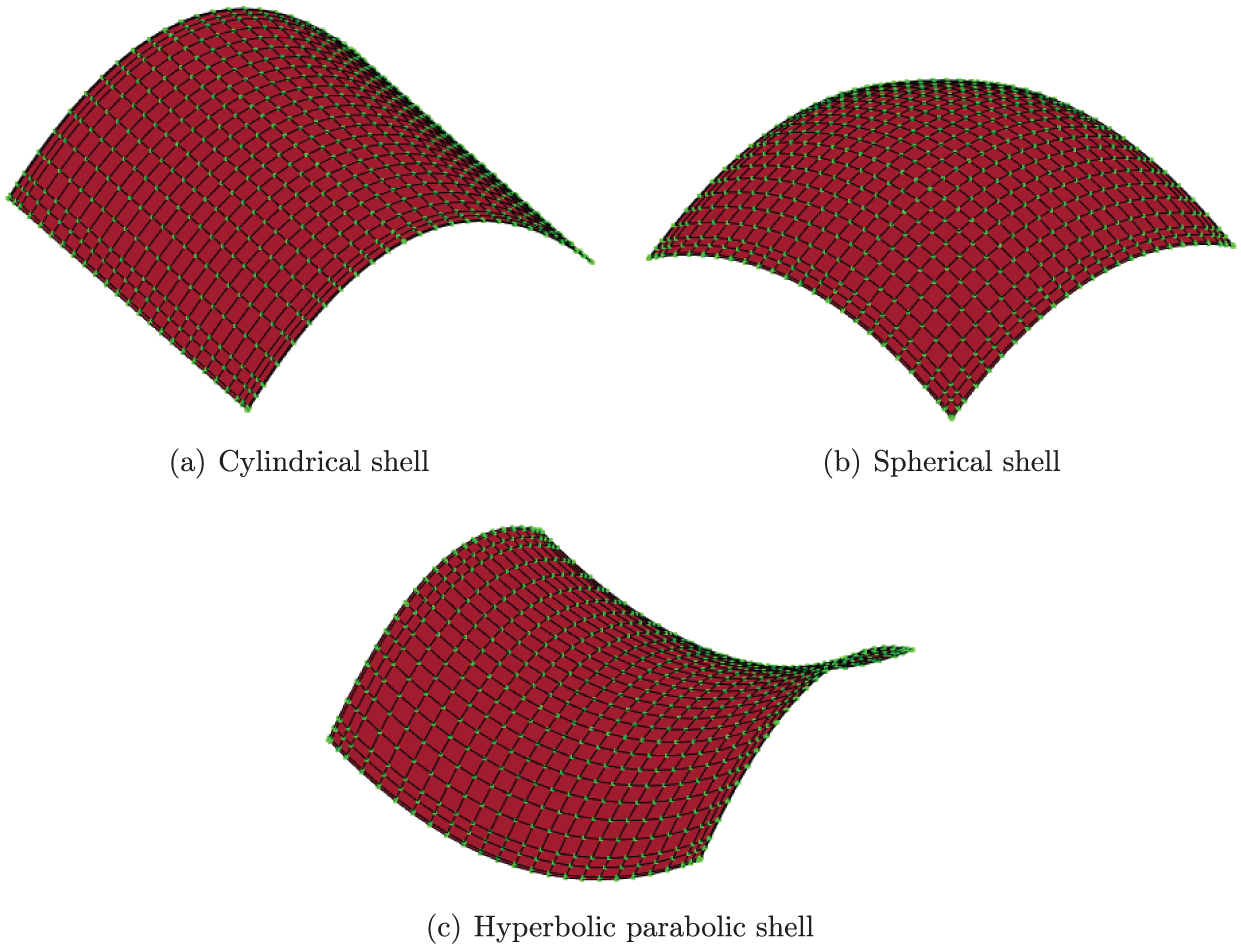
Figure 7: Structural discretization utilizing the meshless moving-Kriging method
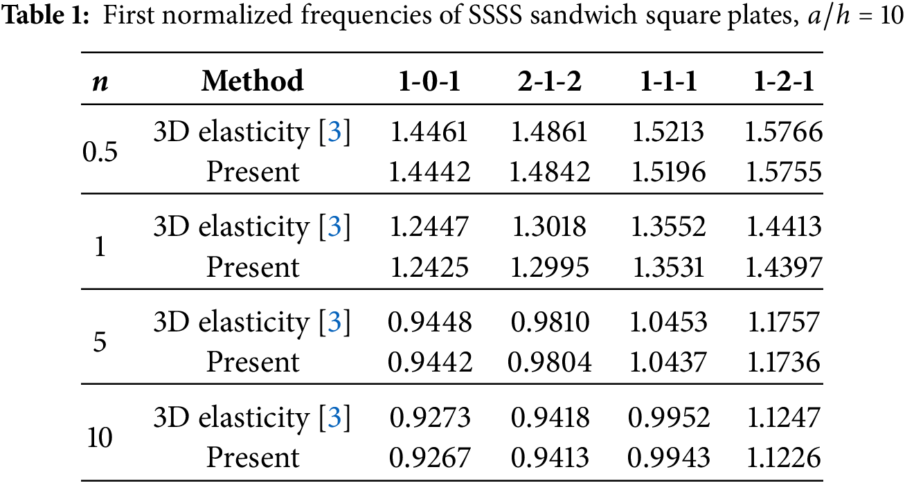
Notably, this is the first study on free-vibration analysis of FGM-FGCNTRC sandwich shells. Thus, solutions for these proposed structures are not available in the literature. However, because square FGM sandwich plates, cylindrical FGCNTRC shells, isotropic spherical and hyperbolic-parabolic shells are particular cases of doubly curved FGM-FGCNTRC sandwich shells. Therefore, the accuracy of the present formulation is, respectively, confirmed by performing free vibration analyses of these structures. Notably, the mechanical properties of FGM and FGCNTRC have been provided at the beginning of this section. In particular, by setting the thicknesses of the two skin layers to zero, the present formulation can be applied to structures with only one layer. This numerical implementation is very simple and can be done quickly using our in-house MATLAB codes.
4.1.1 Square Sandwich Plates with FGM Skins and an Isotropic Core
A square plate is a particular case of a doubly curved shell, with
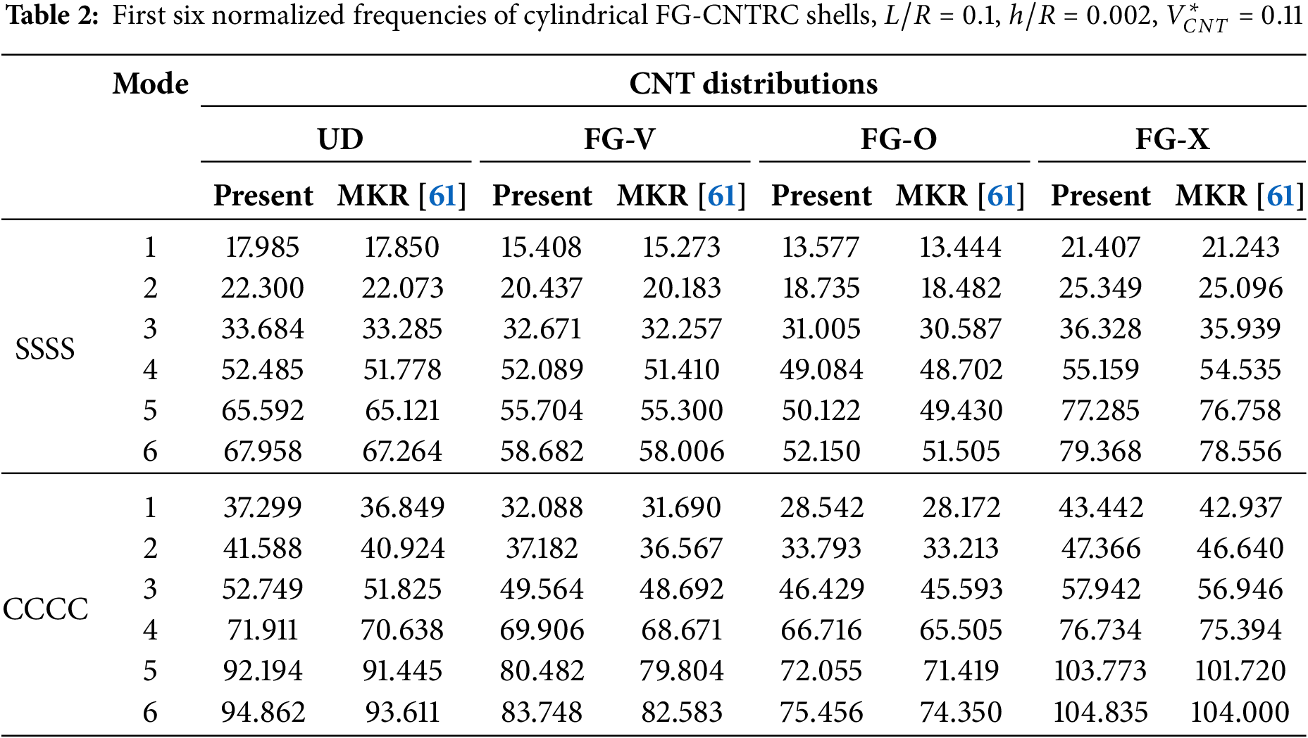
4.1.2 Cylindrical FGCNTRC Shells
Next, we verify the present formulation for the analysis of cylindrical FGCNTRC shells. A cylindrical FGCNTRC panel is shown in Fig. 6, and its geometric properties are
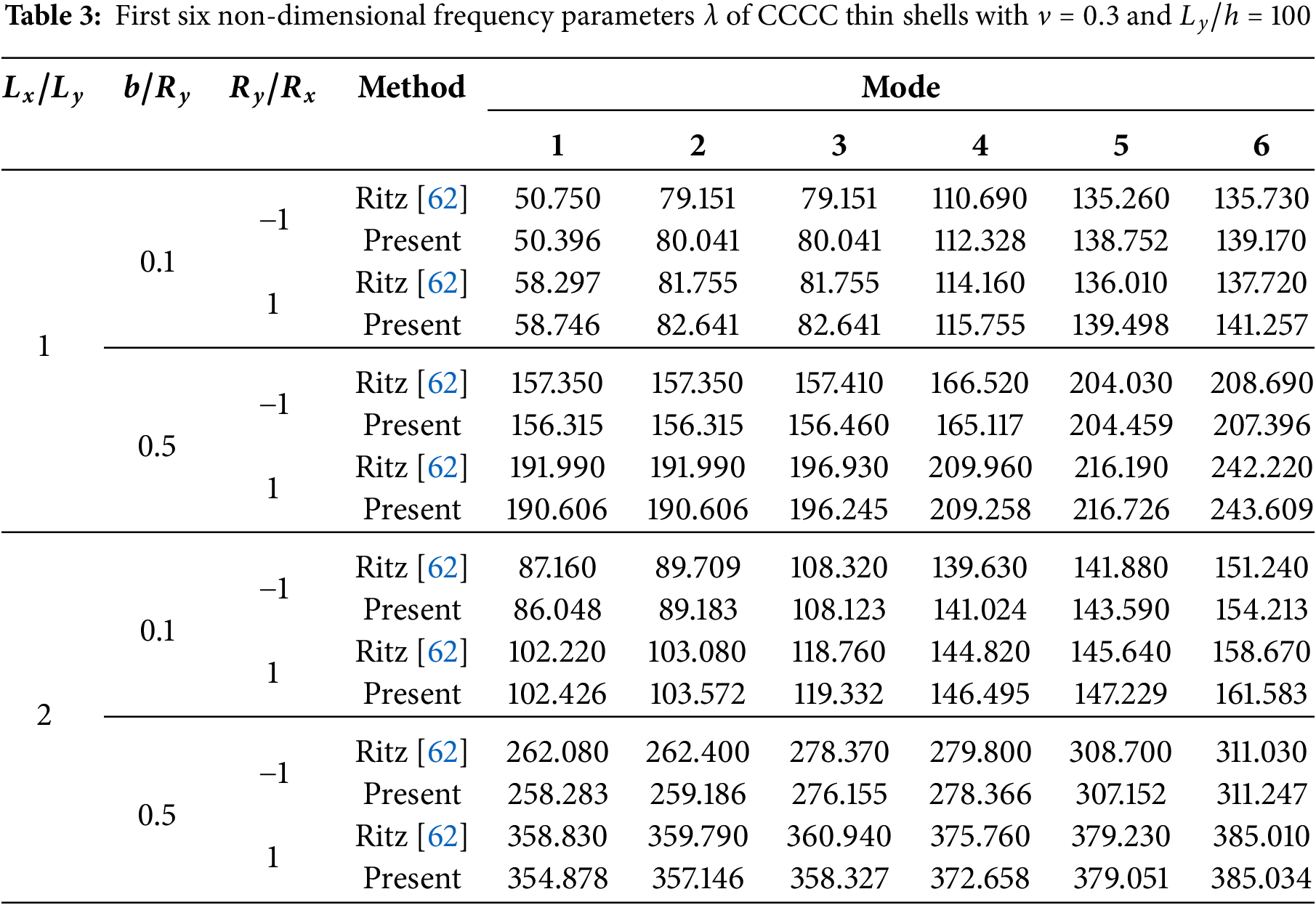
4.1.3 Isotropic Spherical and Hyperbolic-PARabolic Shells
We next carried out a verification of the present formulation for the analysis of isotropic spherical and hyperbolic-parabolic shells. The doubly-curved shell shown in Fig. 8 is considered. Here, Poisson’s ratio is fixed at
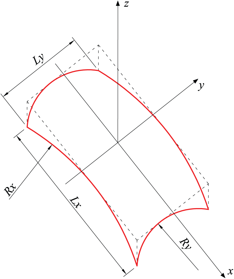
Figure 8: Geometry of a doubly-curved shell
4.2.1 Cylindrical FGM-FGCNTRC Sandwich Shells
We next consider the cylindrical FGM-FGCNTRC sandwich shell shown in Fig. 6. Its geometric properties are
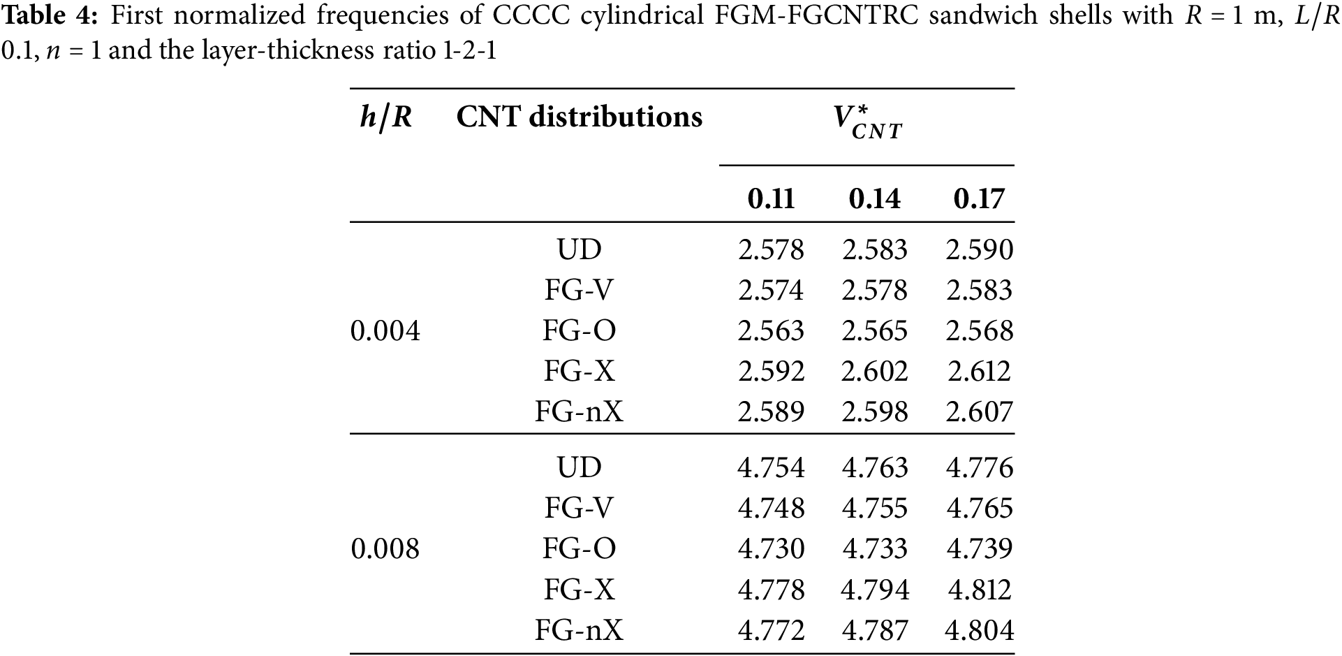
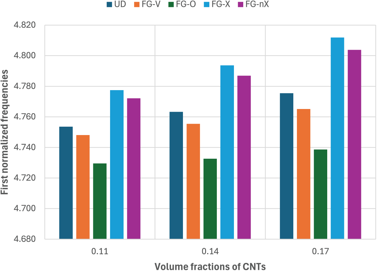
Figure 9: Effect of the CNT distribution on the first normalized frequency of the cylindrical FGM-FGCNTRC sandwich shell with

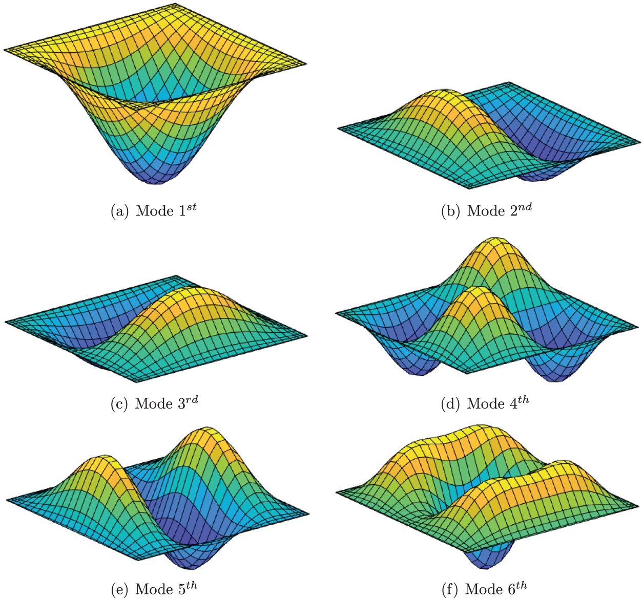
Figure 10: First six mode shapes of a cylindrical FGM-FGCNTRC sandwich shell

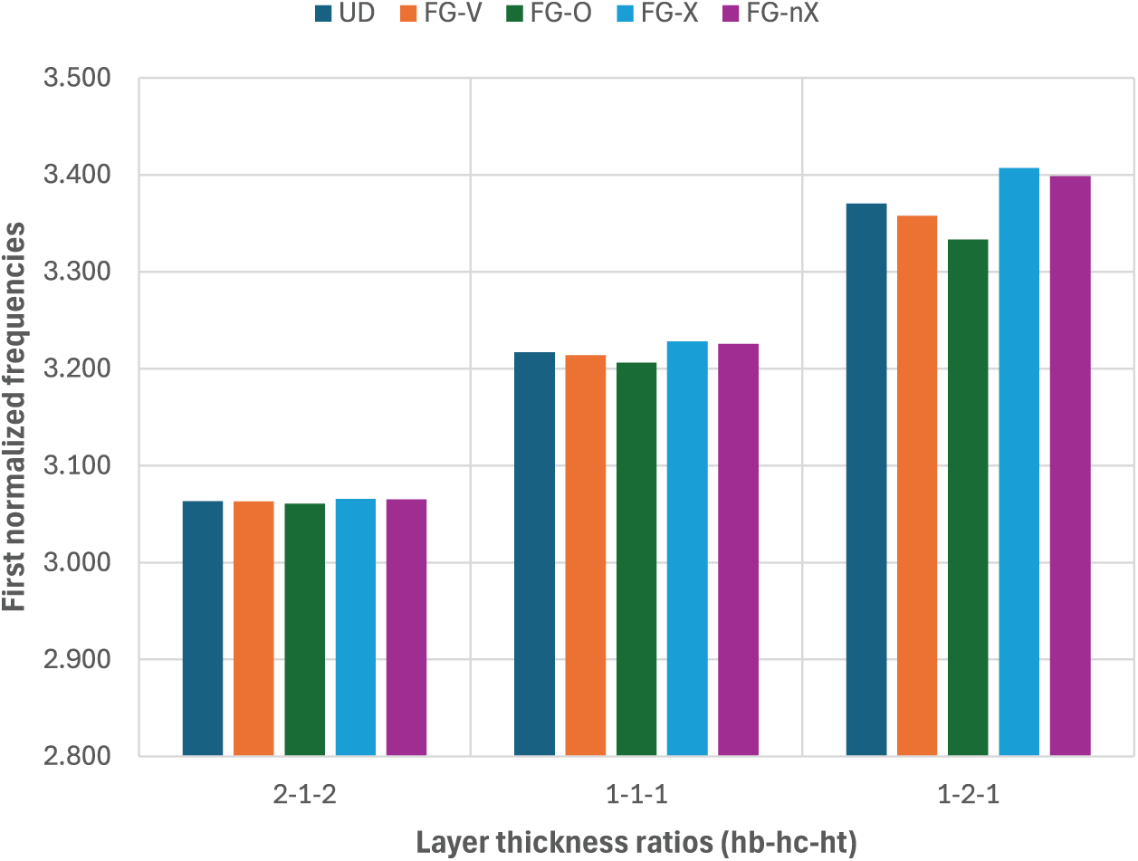
Figure 11: Effect of the layer-thickness ratio on the first normalized frequency of the cylindrical FGM-FGCNTRC sandwich shell with
4.2.2 Spherical FGM-FGCNTRC Sandwich Shells
The spherical FGM-FGCNTRC sandwich shell shown in Fig. 8 is next considered. Its geometric properties are

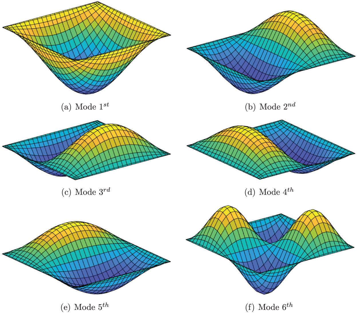
Figure 12: First six mode shapes of a spherical FGM-FGCNTRC sandwich shell

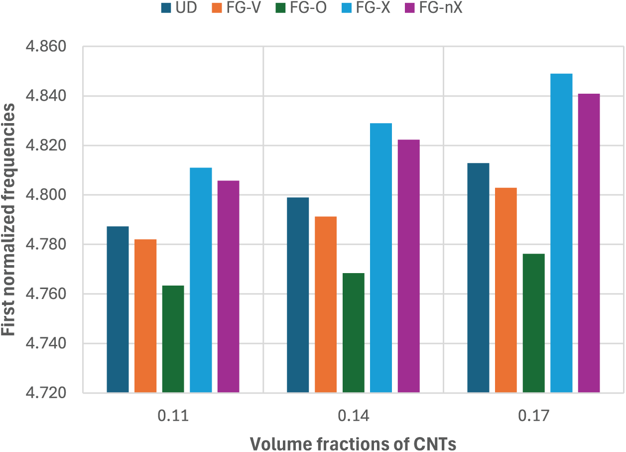
Figure 13: Effect of the CNT distribution on the first normalized frequency of the spherical FGM-FGCNTRC sandwich shell with

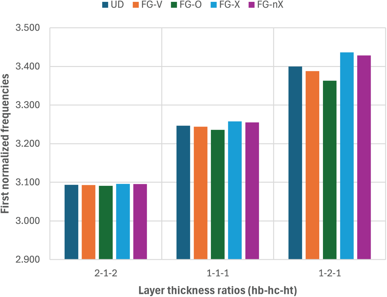
Figure 14: Effect of the layer-thickness ratio on the first normalized frequency of the spherical FGM-FGCNTRC sandwich shell with
4.2.3 Hyperbolic-Parabolic FGM-FGCNTRC Sandwich Shells
The geometries of the shells and the normalized frequency and parameter investigations discussed in this section are the same as those in Section 4.2.2 except that we use


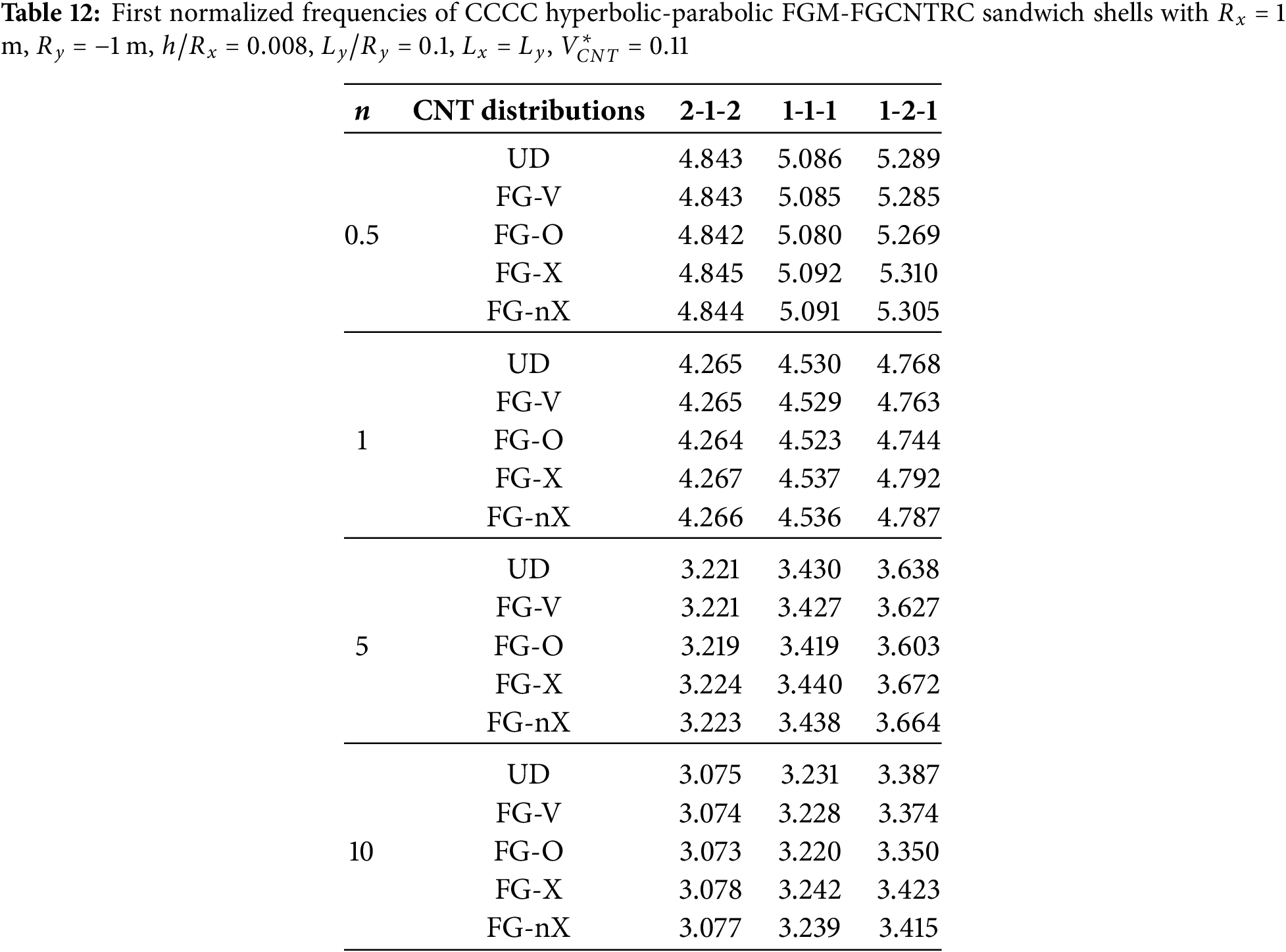
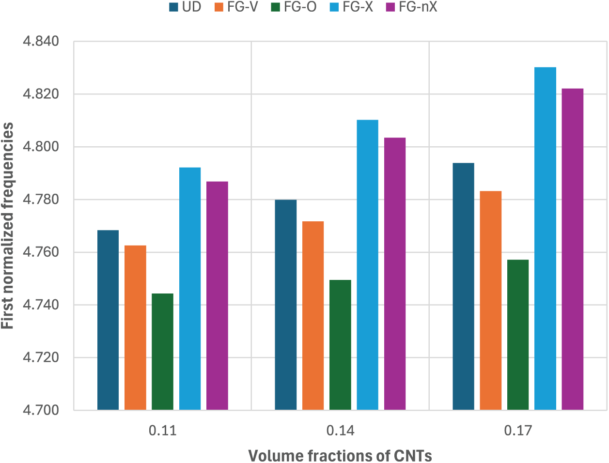
Figure 15: Effect of CNT distribution on the first normalized frequency of the hyperbolic-parabolic FGM-FGCNTRC sandwich shell with
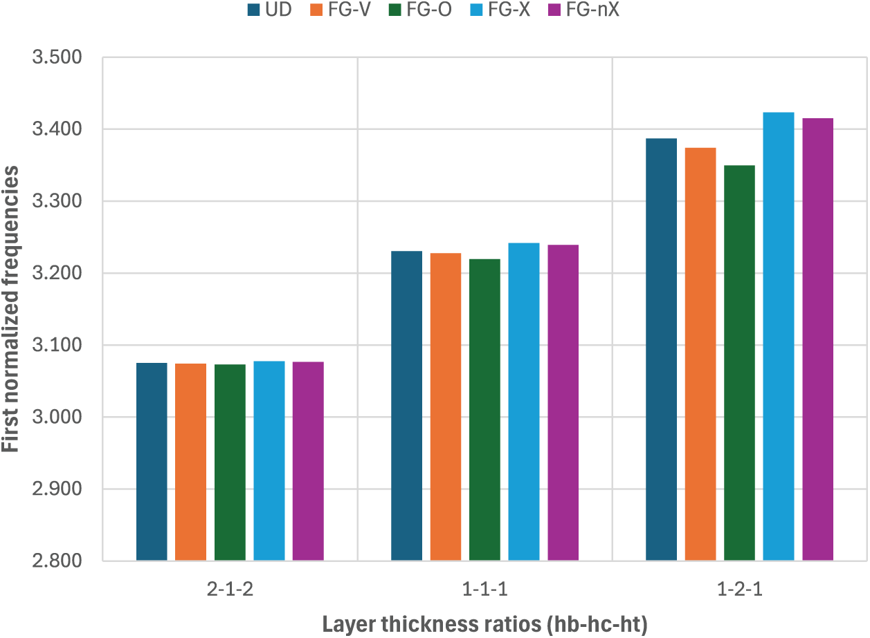
Figure 16: Effect of the layer-thickness ratio on the first normalized frequency of the hyperbolic-parabolic FGM-FGCNTRC sandwich shell with
In this work, we have presented free vibration analyses of FGM-FGCNTRC sandwich shells utilizing an improved meshfree moving-Kriging method and first-order shear deformation shell theory. The effective material characteristics of both the FGM skin layers and the FGCNTRC core were determined using the rule of mixture. The accuracy of the present formulation was confirmed by solving some problems. The obtained results agreed well with the reference ones. Some main parameters and factors such as the thickness-to-radius ratio (
• The greater the amount of CNTs, the higher the stiffness and frequency of the shell. FG-X is the best CNT distribution that produces the highest stiffness and frequency of the shell compared to the rest of the CNT distributions. FG-nX (proposed) produces a higher stiffness and frequency of the shell than do the UD, FG-V, and FG-O distributions.
• The thicker the FGCNTRC core, the higher the stiffness and frequency of the shell. It is found that the effect of the CNT distribution on the frequency of the shell is very small for the case where the layer-thickness ratio is 2-1-2, while it is significant for the case where the layer-thickness ratio is 1-2-1. It is recommended to use FGM-FGCNTRC sandwich shells with the layer-thickness ratio 1-2-1 (or shells with thicker FGCNTRC cores) to efficiently exploit the CNT distribution.
• The higher the thickness-to-radius ratio or the length-to-radius ratio, the higher the stiffness and frequency of the shell.
Although the present approach possesses some advantages and some findings for FGM-FGCNTRC sandwich shells have been recommended, some limitations remain to be overcome. These include the following: 1) The present formulation applies to doubly curved shells, but it needs to be improved for analyzing free-form shells; 2) The meshfree MK method should be improved for reducing the computational cost. Overcoming these limitations can be considered as future work. In addition, some possible future research directions include analyses of the transient vibrations, nonlinear vibrations, and nonlinear forced vibrations of FGM-FGCNTRC sandwich shells.
Acknowledgement: None.
Funding Statement: The authors received no specific funding for this study.
Author Contributions: Study conception and design: Tan N. Nguyen, Nuttawit Wattanasakulpong; Literature review and data collection: Tan N. Nguyen, Suppakit Eiadtrong; Analysis and interpretation of literature: Tan N. Nguyen, Suppakit Eiadtrong, Mohamed-Ouejdi Belarbi; Visualization and graphical representation: Tan N. Nguyen, Suppakit Eiadtrong; Draft manuscript preparation: Tan N. Nguyen, Suppakit Eiadtrong; Critical revision of the manuscript: Tan N. Nguyen, Nuttawit Wattanasakulpong, Mohamed-Ouejdi Belarbi. All authors reviewed the results and approved the final version of the manuscript.
Availability of Data and Materials: Data will be made available on request.
Ethics Approval: No applicable.
Conflicts of Interest: The authors declare no conflicts of interest to report regarding the present study.
References
1. Eiadtrong S, Nguyen TN, Wattanasakulpong N. Nonlinear vibration of sandwich beams made of FGM faces and FGP core under multiple moving loads using a quasi-3D theory. Eng Struct. 2024 Oct;316:118575. doi:10.1016/j.engstruct.2024.118575. [Google Scholar] [CrossRef]
2. Reddy JN. Analysis of functionally graded plates. Int J Numer Methods Eng. 2000 Jan;47:663–84. doi:10.1002/(SICI)1097-0207(20000110/30)47:1/3<663::AID-NME787>3.0.CO;2-8. [Google Scholar] [CrossRef]
3. Li Q, Iu VP, Kou KP. Three-dimensional vibration analysis of functionally graded material sandwich plates. J Sound Vib. 2008 Mar;311(1):498–515. doi:10.1016/j.jsv.2007.09.018. [Google Scholar] [CrossRef]
4. Amir M, Lim J, Kim SW, Lee SY. Finite element analysis of natural frequencies of the FGM porous cooling plate with cutouts: a multilayered FGM approach. Results Eng. 2023 Dec;20:101532. doi:10.1016/j.rineng.2023.101532. [Google Scholar] [CrossRef]
5. Bagheri H, Kiani Y, Eslami MR. Free vibration of FGM conical-spherical shells. Thin-Walled Struct. 2021 Mar;160:107387. doi:10.1016/j.tws.2020.107387. [Google Scholar] [CrossRef]
6. Dai L. Book review: carbon nanotubes and related structures-new materials for the twenty-first century. Peter J. F. Harris. ChemPhysChem. 2002 May;3(5):463–4. doi:10.1002/1439-7641(20020517)3:5<463::AID-CPHC463>3.0.CO;2-C/abstract. [Google Scholar] [CrossRef]
7. Lau AKT, Hui D. The revolutionary creation of new advanced materials-carbon nanotube composites. Compos Part B Eng. 2002 Jun;33(4):263–77. doi:10.1016/s1359-8368(02)00012-4. [Google Scholar] [CrossRef]
8. Thostenson ET, Li C, Chou TW. Nanocomposites in context. Compos Sci Technol. 2005 Mar;65(3):491–516. doi:10.1016/j.compscitech.2004.11.003. [Google Scholar] [CrossRef]
9. Iijima S. Helical microtubules of graphitic carbon. Nature. 1991;354(6348):56–8. doi:10.1038/354056a0. [Google Scholar] [CrossRef]
10. Civalek O, Dastjerdi S, Akgöz B. Buckling and free vibrations of CNT-reinforced cross-ply laminated composite plates. Mech Based Des Struct Mach. 2022 Apr;50:1914–31. doi:10.1080/15397734.2020.1766494. [Google Scholar] [CrossRef]
11. Yee K, Ghayesh MH, Ng CT. Coupled five-parameter dynamics of Mindlin and third-order shear deformable FG graphene-platelets reinforced viscoelastic plates with geometric and material imperfections. Eng Struct. 2023 Dec;297(3–5):116944. doi:10.1016/j.engstruct.2023.116944. [Google Scholar] [CrossRef]
12. Pagani A, Augello R, Carrera E. A high-order shell finite element for the large deformation analysis of soft material structures. Int J Numerical Meth Eng, 125(7):e7417. doi:10.1002/nme.7417. [Google Scholar] [CrossRef]
13. Zhang Q, Li S, Zhang AM, Peng Y, Yan J. A peridynamic Reissner-Mindlin shell theory. Int J Numerical Meth Eng. 2021 Jan;122:122–47. doi:10.1002/nme.6527. [Google Scholar] [CrossRef]
14. Eroǧlu M, Koç MA, Esen I. Thermomechanical free vibration buckling of FG graphene-reinforced doubly-curved sandwich shells. Adv Eng Softw. 2025 Apr;202:103875. doi:10.1016/j.advengsoft.2025.103875. [Google Scholar] [CrossRef]
15. Lakhdar Z, Chorfi SM, Belalia SA, Khedher KM, Alluqmani AE, Tounsi A, et al. Free vibration and bending analysis of porous bi-directional FGM sandwich shell using a TSDT p-version finite element method. Acta Mech. 2024 Jun;235(6):3657–86. doi:10.1007/s00707-024-03909-y. [Google Scholar] [CrossRef]
16. Zhou L, Yang H, Ma L, Zhang S, Li X, Ren S, et al. On the static analysis of inhomogeneous magneto-electro-elastic plates in thermal environment via element-free Galerkin method. Eng Anal Bound Elem. 2022 Jan;134(1):539–52. doi:10.1016/j.enganabound.2021.11.002. [Google Scholar] [CrossRef]
17. Rabczuk T, Areias PMA, Belytschko T. A meshfree thin shell method for non-linear dynamic fracture. Int J Numer Methods Eng. 2007 Oct;72(5):524–48. doi:10.1002/nme.2013. [Google Scholar] [CrossRef]
18. Nguyen TN, Thai CH, Nguyen-Xuan H, Lee J. Geometrically nonlinear analysis of functionally graded material plates using an improved moving Kriging meshfree method based on a refined plate theory. Compos Struct. 2018 Jun;193(1):268–80. doi:10.1016/j.compstruct.2018.03.036. [Google Scholar] [CrossRef]
19. Sadamoto S, Ozdemir M, Tanaka S, Taniguchi K, Yu TT, Bui TQ. An effective meshfree reproducing kernel method for buckling analysis of cylindrical shells with and without cutouts. Comput Mech. 2017;59(6):919–32. doi:10.1007/s00466-017-1384-5.. [Google Scholar] [CrossRef]
20. Nguyen TN, Wattanasakulpong N, Nguyen NP, Fakharian P, Eiadtrong S. Isogeometric analysis of functionally graded triply periodic minimal surface shells. Mech Adv Mater Struct. 2025. doi:10.1080/15376494.2024.2423278. [Google Scholar] [CrossRef]
21. Nguyen TN, Thai CH, Luu AT, Nguyen-Xuan H, Lee J. NURBS-based postbuckling analysis of functionally graded carbon nanotube-reinforced composite shells. Comput Methods Appl Mech Eng. 2019 Apr;347(6348):983–1003. doi:10.1016/j.cma.2019.01.011. [Google Scholar] [CrossRef]
22. Nguyen TN, Hien TD, Nguyen-Thoi T, Lee J. A unified adaptive approach for membrane structures: form finding and large deflection isogeometric analysis. Comput Methods Appl Mech Eng. 2020 Sep;369:113239. doi:10.1016/j.cma.2020.113239. [Google Scholar] [CrossRef]
23. Nguyen SN, Nguyen-Thoi T, Trinh MC, Ho-Nguyen-Tan T, Han JW. Smoothed finite element approach for viscoelastic behaviors of general shell structures. Thin-Walled Struct. 2022 Jul;176(1–4):109323. doi:10.1016/j.tws.2022.109323. [Google Scholar] [CrossRef]
24. Vaghefi R. Analysis of thermo-elastoplastic bending behavior of FG skew sandwich plates on elastic foundation using an enhanced meshless radial basis reproducing kernel particle approach. Arch Appl Mech. 2024;94(11):3195–227. doi:10.1007/s00419-024-02666-7. [Google Scholar] [CrossRef]
25. Najafi M, Dehghan M, Šarler B, Kosec G, Mavrič B. Divergence-free meshless local Petrov-Galerkin method for Stokes flow. Eng Comput. 2022 Dec;38(6):5359–77. doi:10.1007/s00366-022-01621-w. [Google Scholar] [CrossRef]
26. Tomar S, Singh M, Vajravelu K, Ramos H. Simplifying the variational iteration method: a new approach to obtain the Lagrange multiplier. Math Comput Simul. 2023 Feb;204(7–8):640–4. doi:10.1016/j.matcom.2022.09.003. [Google Scholar] [CrossRef]
27. Gao H, Wei G. A meshless solution of nonlinear elastoplastic problems based on the RRKPM. Results Phys. 2021 Dec;31:104986. doi:10.1016/j.rinp.2021.104986. [Google Scholar] [CrossRef]
28. Krongauz Y, Belytschko T. Enforcement of essential boundary conditions in meshless approximations using finite elements. Comput Methods Appl Mech Eng. 1996 Apr;131(1):133–45. doi:10.1016/0045-7825(95)00954-x. [Google Scholar] [CrossRef]
29. Gu L. Moving kriging interpolation and element-free Galerkin method. Int J Numerical Meth Eng. 2003 Jan;56:1–11. doi:10.1002/nme.553. [Google Scholar] [CrossRef]
30. Tongsuk P, Kanok-Nukulchai W. Further investigation of element-free galerkin method using moving kriging interpolation. Int J Comput Methods. 2004 Sep;01(02):345–65. doi:10.1142/S0219876204000162. [Google Scholar] [CrossRef]
31. Bui TQ, Nguyen TN, Nguyen-Dang H. A moving Kriging interpolation-based meshless method for numerical simulation of Kirchhoff plate problems. Int J Numer Meth Eng. 2009 Mar;77:1371–95. doi:10.1002/nme.2462. [Google Scholar] [CrossRef]
32. Sayakoummane V, Kanok-Nukulchai W. A meshless analysis of shells based on moving kriging interpolation. Int J Comput Meth. 2007 Dec;04:543–65. doi:10.1142/S0219876207000935. [Google Scholar] [CrossRef]
33. Bui TQ, Nguyen MN, Zhang C, Pham DAK. An efficient meshfree method for analysis of two-dimensional piezoelectric structures. Smart Mater Struct. 2011 May;20(6):065016. doi:10.1088/0964-1726/20/6/065016. [Google Scholar] [CrossRef]
34. Bui TQ, Nguyen MN, Zhang C. An efficient meshfree method for vibration analysis of laminated composite plates. Comput Mech. 2011 Aug;48(2):175–93. doi:10.1007/s00466-011-0591-8. [Google Scholar] [CrossRef]
35. Nguyen TN, Thai CH, Nguyen-Xuan H. A novel computational approach for functionally graded isotropic and sandwich plate structures based on a rotation-free meshfree method. Thin-Walled Struct. 2016 Oct;107(6–8):473–88. doi:10.1016/j.tws.2016.06.011. [Google Scholar] [CrossRef]
36. Thai CH, Nguyen TN, Rabczuk T, Nguyen-Xuan H. An improved moving Kriging meshfree method for plate analysis using a refined plate theory. Comput Struct. 2016 Nov;176(1):34–49. doi:10.1016/j.compstruc.2016.07.009. [Google Scholar] [CrossRef]
37. Thai CH, Do VNV, Nguyen-Xuan H. An improved moving Kriging-based meshfree method for static, dynamic and buckling analyses of functionally graded isotropic and sandwich plates. Eng Anal Bound Elem. 2016 Mar;64(12):122–36. doi:10.1016/j.enganabound.2015.12.003. [Google Scholar] [CrossRef]
38. Pandey S, Pradyumna S. Transient stress analysis of sandwich plate and shell panels with functionally graded material core under thermal shock. J Therm Stresses. 2018 May;41:543–67. doi:10.1080/01495739.2017.1422999. [Google Scholar] [CrossRef]
39. Pandey S, Pradyumna S. A finite element formulation for thermally induced vibrations of functionally graded material sandwich plates and shell panels. Compos Struct. 2017 Jan;160(2):877–86. doi:10.1016/j.compstruct.2016.10.040. [Google Scholar] [CrossRef]
40. Fu T, Wu X, Xiao Z, Chen Z. Study on dynamic instability characteristics of functionally graded material sandwich conical shells with arbitrary boundary conditions. Mech Syst Signal Process. 2021 Apr;151(5):107438. doi:10.1016/j.ymssp.2020.107438. [Google Scholar] [CrossRef]
41. Dung DV, Hoa LK, Thuyet BT, Nga NT. Buckling analysis of functionally graded material (FGM) sandwich truncated conical shells reinforced by FGM stiffeners filled inside by elastic foundations. Appl Math Mech. 2016 Jul;37(7):879–902. doi:10.1007/s10483-016-2097-9. [Google Scholar] [CrossRef]
42. Moita JS, Araújo AL, Mota Soares CM, Mota Soares CA. Vibration analysis of functionally graded material sandwich structures with passive damping. Compos Struct. 2018 Jan;183:407–15. doi:10.1016/j.compstruct.2017.04.045. [Google Scholar] [CrossRef]
43. Dung DV, Nga NT, Hoa LK. Nonlinear stability of functionally graded material (FGM) sandwich cylindrical shells reinforced by FGM stiffeners in thermal environment. Appl Math Mech. 2017 May;38(5):647–70. doi:10.1007/s10483-017-2198-9. [Google Scholar] [CrossRef]
44. Fu T, Wu X, Xiao Z, Chen Z, Li J. Vibro-acoustic characteristics of eccentrically stiffened functionally graded material sandwich cylindrical shell under external mean fluid. Appl Math Model. 2021 Mar;91(2):214–31. doi:10.1016/j.apm.2020.09.061. [Google Scholar] [CrossRef]
45. Mehar K, Panda SK, Mahapatra TR. Nonlinear frequency responses of functionally graded carbon nanotube-reinforced sandwich curved panel under uniform temperature field. Int J Appl Mech. 2018 Apr;10(3):1850028. doi:10.1142/S175882511850028X. [Google Scholar] [CrossRef]
46. Tung HV, Trang LTN. Nonlinear stability of advanced sandwich cylindrical shells comprising porous functionally graded material and carbon nanotube reinforced composite layers under elevated temperature. Appl Math Mech. 2021 Sep;42(9):1327–48. doi:10.1007/s10483-021-2771-6. [Google Scholar] [CrossRef]
47. Ninh DG, Ha NH, Long NT, Tan NC, Tien ND, Dao DV. Thermal vibrations of complex-generatrix shells made of sandwich CNTRC sheets on both sides and open/closed cellular functionally graded porous core. Thin-Walled Struct. 2023;182(7):110161. doi:10.1016/j.tws.2022.110161. [Google Scholar] [CrossRef]
48. Duc ND, Seung-Eock K, Khoa ND, Chan DQ. Nonlinear buckling and post-buckling analysis of shear deformable stiffened truncated conical sandwich shells with functionally graded face sheets and a functionally graded porous core. J Sandw Struct Mater. 2021 Oct;23:2700–35. doi:10.1177/1099636220906821. [Google Scholar] [CrossRef]
49. Wang YQ, Xing WC, Wang J, Chai Q. Theoretical and experimental studies on vibration characteristics of bolted joint multi-plate structures. Int J Mech Sci. 2023 Aug;252:108348. doi:10.1016/j.ijmecsci.2023.108348. [Google Scholar] [CrossRef]
50. Zhu P, Lei ZX, Liew KM. Static and free vibration analyses of carbon nanotube-reinforced composite plates using finite element method with first order shear deformation plate theory. Compos Struct. 2012 Mar;94(4):1450–60. doi:10.1016/j.compstruct.2011.11.010. [Google Scholar] [CrossRef]
51. Li X, Gao H, Scrivens WA, Fei D, Xu X, Sutton MA, et al. Reinforcing mechanisms of single-walled carbon nanotube-reinforced polymer composites. J Nanosci Nanotechnol. 2007 Jul;7(7):2309–17. [Google Scholar]
52. Esawi AMK, Farag MM. Carbon nanotube reinforced composites: potential and current challenges. Mater Des. 2007 Jan;28(9):2394–401. doi:10.1016/j.matdes.2006.09.022. [Google Scholar] [CrossRef]
53. Seidel GD, Lagoudas DC. Micromechanical analysis of the effective elastic properties of carbon nanotube reinforced composites. Mech Mater. 2006 Aug;38(8):884–907. doi:10.1016/j.mechmat.2005.06.029. [Google Scholar] [CrossRef]
54. Anumandla V, Gibson RF. A comprehensive closed form micromechanics model for estimating the elastic modulus of nanotube-reinforced composites. Compos Part A Appl Sci Manuf. 2006 Dec;37(12):2178–85. doi:10.1016/j.compositesa.2005.09.016. [Google Scholar] [CrossRef]
55. Sobhani Aragh B, Nasrollah Barati AH, Hedayati H. Eshelby-Mori-Tanaka approach for vibrational behavior of continuously graded carbon nanotube-reinforced cylindrical panels. Compos Part B Eng. 2012 Jun;43(4):1943–54. doi:10.1016/j.compositesb.2012.01.004. [Google Scholar] [CrossRef]
56. Wang J, Pyrz R. Prediction of the overall moduli of layered silicate-reinforced nanocomposites—part I: basic theory and formulas. Compos Sci Technol. 2004 Jun;64(7):925–34. doi:10.1016/s0266-3538(03)00024-1. [Google Scholar] [CrossRef]
57. Shen HS, Zhang CL. Thermal buckling and postbuckling behavior of functionally graded carbon nanotube-reinforced composite plates. Mater Des. 2010 Aug;31(7):3403–11. doi:10.1016/j.matdes.2010.01.048. [Google Scholar] [CrossRef]
58. Shen HS. Nonlinear bending of functionally graded carbon nanotube-reinforced composite plates in thermal environments. Compos Struct. 2009;91(1):9–19. doi:10.1016/j.compstruct.2009.04.026. [Google Scholar] [CrossRef]
59. Reddy JN. Mechanics of laminated composite plates and shells: theory and analysis. Boca Raton, FL, USA: CRC Press; 2003. [Google Scholar]
60. Nguyen TN, Lee S, Nguyen-Xuan H, Lee J. A novel analysis-prediction approach for geometrically nonlinear problems using group method of data handling. Comput Methods Appl Mech Eng. 2019 Sep;354(1):506–26. doi:10.1016/j.cma.2019.05.052. [Google Scholar] [CrossRef]
61. Zhang LW, Lei ZX, Liew KM, Yu JL. Static and dynamic of carbon nanotube reinforced functionally graded cylindrical panels. Compos Struct. 2014 May;111:205–12. doi:10.1016/j.compstruct.2013.12.035. [Google Scholar] [CrossRef]
62. Liew KM, Lim CW. Vibration of doubly-curved shallow shells. Acta Mech. 1996 Mar;114(1):95–119. doi:10.1007/BF01170398. [Google Scholar] [CrossRef]
Cite This Article
 Copyright © 2025 The Author(s). Published by Tech Science Press.
This work is licensed under a Creative Commons Attribution 4.0 International License , which permits unrestricted use, distribution, and reproduction in any medium, provided the original work is properly cited.
 Downloads
 Citation Tools