
 Submit a Paper
 Propose a Special lssue
 Open Access
ARTICLE

An Automated Adaptive Finite Element Methodology for 2D Linear Elastic Fatigue Crack Growth Simulation
Department of Mechanical Engineering, College of Engineering and Computer Sciences, Jazan University, Jazan, 45142, Saudi Arabia
* Corresponding Author: Abdulnaser M. Alshoaibi. Email:
(This article belongs to the Special Issue: Advances in Computational Fracture Mechanics: Theories, Techniques, and Applications)
Computer Modeling in Engineering & Sciences 2025, 145(1), 189-214. https://doi.org/10.32604/cmes.2025.071583
Received 07 August 2025; Accepted 09 October 2025; Issue published 30 October 2025
 View Full Text
 Download PDF
Abstract
Fatigue crack growth is a critical phenomenon in engineering structures, accounting for a significant percentage of structural failures across various industries. Accurate prediction of crack initiation, propagation paths, and fatigue life is essential for ensuring structural integrity and optimizing maintenance schedules. This paper presents a comprehensive finite element approach for simulating two-dimensional fatigue crack growth under linear elastic conditions with adaptive mesh generation. The source code for the program was developed in Fortran 95 and compiled with Visual Fortran. To achieve high-fidelity simulations, the methodology integrates several key features: it employs an automatic, adaptive meshing technique that selectively refines the element density near the crack front and areas of significant stress concentration. Specialized singular elements are used at the crack tip to ensure precise stress field representation. The direction of crack advancement is predicted using the maximum tangential stress criterion, while stress intensity factors are determined through either the displacement extrapolation technique or the J-integral method. The simulation models crack growth as a series of linear increments, with solution stability maintained by a consistent transfer algorithm and a crack relaxation method. The framework’s effectiveness is demonstrated across various geometries and loading scenarios. Through rigorous validation against both experimental data and established numerical benchmarks, the approach is proven to accurately forecast crack trajectories and fatigue life. Furthermore, the detailed description of the program’s architecture offers a foundational blueprint, serving as a valuable guide for researchers aiming to develop their specialized software for fracture mechanics analysis.Keywords
Fatigue crack growth is a critical phenomenon in engineering structures subjected to cyclic loading, accounting for a significant percentage of structural failures across industries. Recent studies estimate that fatigue-related failures represent approximately 50%–90% of all mechanical failures in industrial components [1–3]. The ability to accurately predict crack initiation, propagation paths, and fatigue life is essential for ensuring structural integrity, optimizing maintenance schedules, and preventing catastrophic failures. Over the past decades, computational modeling has emerged as a powerful tool for simulating fatigue crack growth, complementing traditional experimental approaches and enabling more efficient and cost-effective design processes in two and three dimensions. Linear Elastic Fracture Mechanics (LEFM) provides a theoretical framework for analyzing crack growth in materials where plastic deformation is limited to a small region around the crack tip. Within this framework, the stress intensity factor (K) characterizes the stress field at the crack tip and serves as the primary parameter governing crack propagation. For fatigue crack growth analysis, the range of stress intensity factor (ΔK) during a loading cycle is the key driver of crack propagation, typically described by the Paris law:
where da/dN is the crack growth rate, ΔK is the stress intensity factor range, and C and m are material constants determined experimentally. While this classical relationship remains foundational, recent research has extended its application to more complex scenarios, including variable amplitude loading, environmental effects, and functionally graded materials [4].
The finite element method (FEM) has been widely adopted for numerical simulation of fatigue crack growth due to its versatility in handling complex geometries and loading conditions. However, conventional FEM approaches face challenges in accurately capturing the stress singularity at the crack tip and efficiently updating the mesh as the crack propagates. These challenges have motivated the development of specialized techniques, including singular elements at the crack tip and adaptive mesh refinement strategies. Jaccon et al. [5] demonstrated that coupling adaptive mesh refinement with cycle jump techniques can significantly accelerate computation time while maintaining solution accuracy, making it feasible to simulate high-cycle fatigue scenarios that were previously computationally prohibitive. Adaptive mesh generation is particularly valuable in fracture mechanics simulations, as it allows for optimal allocation of computational resources by refining the mesh in regions of high stress gradients (especially near the crack tip) while maintaining a coarser mesh elsewhere. This approach not only improves accuracy but also enhances computational efficiency, making it possible to simulate complex crack growth scenarios with reasonable computational resources. The advancing front method represents one particularly effective approach for generating high-quality meshes that adapt to evolving crack geometries during propagation simulations. Recent advancements in the fracture mechanics field include sophisticated modeling techniques, such as the stress-intensity-factor-driven phase field approach for mixed-mode fracture analysis, which offers a more comprehensive understanding of complex crack behaviors by bridging phase-field formulations with linear elastic fracture mechanics [6]. Concurrently, research continues to address practical challenges like the fatigue crack propagation in corroded steel box girders found in long-span bridges, highlighting the ongoing need for robust predictive models and material characterization under adverse conditions [7]. Furthermore, recent studies by Thiruvannamalai et al. [8] have shown that adaptive meshing techniques can reduce simulation time compared to uniform refinement while maintaining solution accuracy within 2% of analytical benchmarks. Furthermore, Zhang et al. [9] introduced an adaptive phase-field framework with variable-node elements that significantly improves the efficiency of crack nucleation and propagation simulations in brittle materials. The field of structural optimization has seen significant advancements, particularly in addressing complex real-world challenges such as fatigue. In this context, recent research has focused on integrating advanced crack propagation analysis into topology optimization methodologies. For instance, one notable study introduces an advanced structural topology optimization approach that integrates fatigue crack propagation analysis. Utilizing the Extended Finite Element Method (X-FEM) for initial crack propagation and the Paris model for fatigue crack growth, the methodology aims to minimize structural compliance under volume and fatigue constraints. The proposed bi-directional evolutionary structural optimization (BESO) algorithm effectively adapts material distribution based on various crack conditions, including presence, direction, and length. The results demonstrate the algorithm’s ability to achieve optimal topologies that balance structural integrity and performance, highlighting the significant influence of crack characteristics on the final design and structural stiffness [10]. To further strengthen the scientific scope and neutrality of this study, it is pertinent to acknowledge and briefly discuss recent advancements in alternative and complementary methodologies for fatigue crack growth simulation. These include the Extended Finite Element Method (XFEM), phase-field approaches, and modern adaptive remeshing techniques, which offer distinct advantages and address various challenges in fracture mechanics. XFEM has emerged as a powerful tool for simulating crack propagation without the need for continuous remeshing along the crack path, significantly simplifying the modeling of complex crack geometries and arbitrary crack growth [11,12]. Recent studies have demonstrated XFEM’s effectiveness in various fatigue crack growth scenarios, including those in welded joints and cladded structures [13,14]. While, phase-field models represent cracks as diffuse zones rather than sharp discontinuities, offering a robust framework for simulating complex fracture phenomena such as crack initiation, propagation, and branching, especially in brittle and quasi-brittle materials [5,15]. These methods are particularly adept at handling multiple interacting cracks and complex crack patterns without explicit crack tracking algorithms. Recent research has focused on adaptive finite element methods for phase-field fracture to improve computational efficiency while maintaining accuracy [16].
Such developments are crucial for designing robust and durable structures under cyclic loading conditions. The accurate calculation of stress intensity factors (SIFs) remains a critical aspect of fatigue crack growth simulation. Among various methods, the displacement extrapolation technique has gained prominence due to its relative simplicity and accuracy. This method involves extrapolating the displacement field near the crack tip to determine the SIFs. The splitting node approach represents a significant advancement in computational fracture mechanics. This methodology enables precise tracking of crack propagation by duplicating nodes along the predicted fracture path, effectively creating new surfaces that represent the physical separation of material. In computational fracture mechanics, the evaluation of strain energy fields or displacement openings near crack tips is conducted based on fundamental mechanical principles. When these parameters surpass their critical thresholds, crack propagation occurs as a natural consequence of the material’s response to loading conditions. The integration of these methodologies—splitting node approach, displacement extrapolation technique, adaptive meshing, and linear elastic fracture mechanics principles—creates a powerful computational framework for investigating complex fracture phenomena. This integrated approach enables researchers to predict crack initiation, propagation paths, and ultimate failure conditions across a diverse range of materials and loading scenarios with unprecedented accuracy. The implementation of three-dimensional re-meshing algorithms presents substantial computational challenges compared to two-dimensional analyses. These challenges include more complex geometry representation, increased computational resources, and sophisticated mesh adaptation strategies. Despite these differences, research has demonstrated that stress intensity factor predictions in both 2D and 3D simulations achieve remarkable consistency when equivalent mesh refinement techniques are applied [17,18]. This convergence validates the robustness of the underlying mathematical models across dimensional frameworks. The developed computational platform employs finite element methodologies that produce results comparable to those obtained from established commercial fracture analysis software. However, commercially available software packages often present limitations in two critical aspects: they frequently operate as “black boxes” with limited transparency regarding their core algorithms, and they may not incorporate state-of-the-art programming techniques that enhance computational efficiency and accuracy. These limitations underscore the importance of developing specialized research-oriented software that provides full algorithmic transparency and leverages cutting-edge programming methodologies. For more than two decades, this software has been refined to accurately model 2D fatigue crack growth, incorporating LEFM assumptions. The effectiveness of the computational approach has been validated through extensive testing across diverse specimen configurations [19,20].
This paper presents a comprehensive finite element approach for simulating two-dimensional fatigue crack growth under linear elastic conditions with adaptive mesh generation. The methodology incorporates several key features:
1. Automatic adaptive mesh refinement in the vicinity of the crack front and regions of high stress gradients, building on recent advancements in error estimation and mesh quality control.
2. Singular crack tip elements to accurately capture the stress singularity, incorporating the latest developments in element formulation for fracture mechanics.
3. Displacement extrapolation technique for stress intensity factor calculation, enhanced with recent improvements in accuracy and robustness.
4. Maximum tangential stress criterion for crack growth direction determination, validated against contemporary experimental studies.
5. Paris law for fatigue life prediction.
This paper introduces an automated adaptive finite element methodology for 2D linear elastic fatigue crack growth simulation. While building upon established principles of fracture mechanics and numerical methods, the framework’s primary novelty stems from the synergistic integration, specific enhancements, and robust implementation of several key components within a custom-developed, transparent computational tool. This integrated approach enables robust and efficient simulation of complex crack propagation scenarios that are often challenging for conventional or ‘black-box’ commercial software, offering significant advancements in algorithmic aspects, accuracy, and efficiency compared to existing methods.
This framework presents notable algorithmic advancements, including a highly integrated and automated adaptive mesh refinement strategy that precisely refines the mesh around crack fronts. This is coupled with a robust crack propagation algorithm featuring a consistent transfer and crack relaxation method, ensuring solution stability and accuracy during complex crack growth while minimizing re-meshing to only the affected regions. Furthermore, the entire framework is implemented in a transparent, modular Fortran 95 code, providing researchers with full algorithmic access for further development and customization. These algorithmic innovations lead to enhanced accuracy through the integration of specialized singular crack tip elements directly into the adaptive meshing scheme, ensuring high-precision capture of stress singularities at every crack increment. This, combined with an enhanced displacement extrapolation technique, yields more reliable SIF calculations and accurate fatigue life predictions. This approach distinguishes itself from the Extended Finite Element Method (XFEM), which uses enrichment functions to decouple cracks from the mesh [21,22]. In contrast, the present adaptive FEM maintains explicit control over mesh quality and element alignment with the crack path. This meticulous control is critical for accurately capturing stress fields and SIFs in highly localized regions. While XFEM avoids re-meshing, our method focuses on optimizing the mesh locally to the crack path, ensuring high-fidelity stress and displacement fields directly from the mesh geometry, which can offer competitive efficiency for 2D linear elastic problems. Moreover, our framework differs from Phase-Field models, which represent cracks as diffuse zones governed by a continuous phase-field variable. While powerful for complex crack phenomena, phase-field models often require extensive parameter calibration and very fine meshes, leading to high computational costs [23,24]. The present LEFM-based framework, with its explicit crack tracking, is specifically accurate alternative for specific LEFM applications, especially when leveraging our advanced adaptive meshing and solution transfer techniques. The proposed approach is implemented in a custom finite element software that handles arbitrary 2D geometries under constant amplitude loading. The software focuses on determining crack paths and stresses as well as evaluating component lifetimes as part of damage-tolerant assessment.
2 Computational Framework Procedure
The evolution of computational fracture mechanics has consistently demonstrated that mesh refinement strategies play a pivotal role in simulation accuracy and efficiency. It has been conclusively established that strategic mesh refinement in crack problems significantly enhances calculation precision while introducing a critical trade-off with computational resources. Rather than applying uniform refinement across the entire domain, which leads to prohibitive computational costs, adaptive refinement techniques selectively concentrate elements where they provide maximum benefit, particularly in regions with high stress gradients near crack tips. The development of the present software, which began in 2004, represents a sustained research effort that has progressively incorporated sophisticated features across multiple versions to optimize this balance between accuracy and efficiency [19,25]. The program has evolved to include robust unstructured triangular mesh generation, specialized rosette elements around crack tips, automated adaptive refinement based on error estimation, and precise stress intensity factor calculation methods—all within the framework of two-dimensional fatigue crack growth simulation under Linear Elastic Fracture Mechanics (LEFM) assumptions. This evolutionary approach has resulted in a computational methodology that reduces simulation time by 65%–80% compared to uniform refinement while maintaining solution accuracy within 2% of analytical benchmarks [26–28]. The software’s modular architecture facilitates ongoing enhancement, allowing it to address increasingly complex fracture scenarios, including mixed-mode loading conditions and geometric discontinuities that significantly influence crack propagation paths and fatigue life predictions.
2.1 Overview of the Computational Framework
This program is a comprehensive two-dimensional fatigue crack growth simulation tool, designed to model and analyze the propagation of cracks under cyclic loading conditions. The program’s source code was written in Fortran 95 using the Visual Fortran compiler. It is structured around 99 distinct subroutines, each dedicated to a specific task within the larger simulation framework. The proposed methodology for two-dimensional fatigue crack growth simulation under linear elastic conditions with adaptive mesh generation consists of three main components:
1. Preprocessing: Geometry definition, initial crack configuration, and adaptive mesh generation
2. Processing: Finite element analysis with singular crack tip elements
3. Postprocessing: Stress intensity factor calculation, crack growth direction determination, and fatigue life prediction
This integrated approach enables accurate simulation of fatigue crack propagation in arbitrary 2D geometries under constant amplitude loading, with particular emphasis on adaptive mesh generation to ensure optimal computational efficiency.
The simulation begins by declaring essential variables and establishing connections to numerous data files. These files are crucial for both inputting initial conditions (e.g., geometry.dat, material.dat) and outputting results at various stages of the simulation (e.g., displace.dat, stressgp.dat). The IMPLICIT NONE statement, characteristic of modern Fortran, ensures that all variables are explicitly declared, preventing common programming errors. The main subroutines required for use in the program are listed in Appendix A.
• Initializing the Crack Growth Simulation
! PROGRAM 2D Finite Element Simulation for Fatigue Crack Growth
USE PORTLIB
IMPLICIT NONE
INTEGER:: mesh_iter,maxmesh_iter=1,maxgrow=10,kgrow
REAL*8:: elapse_time
LOGICAL:: igrow
! Input files (STATUS=‘OLD’)
OPEN(10,FILE=‘geometry.dat’,STATUS=‘OLD’)
OPEN(11,FILE=‘cracktip.dat’,STATUS=‘OLD’)
OPEN(16,FILE=‘fixnload.dat’,STATUS=‘OLD’)
OPEN(18,FILE=‘material.dat’,STATUS=‘OLD’)
OPEN(25,FILE=‘controel.dat’,STATUS=‘OLD’)
! Output/Scratch files (STATUS=‘REPLACE’)
OPEN(12,FILE=‘georoset.dat’,STATUS=‘REPLACE’)
OPEN(13,FILE=‘initmesh.dat’,STATUS=‘REPLACE’)
OPEN(14,FILE=‘intervar.dat’,STATUS=‘REPLACE’)
OPEN(15,FILE=‘tempmesh.dat’,STATUS=‘REPLACE’)
OPEN(17,FILE=‘fulldata.dat’,STATUS=‘REPLACE’)
OPEN(19,FILE=‘displace.dat’,STATUS=‘REPLACE’)
OPEN(20,FILE=‘stressgp.dat’,STATUS=‘REPLACE’)
OPEN(21,FILE=‘stressnd.dat’,STATUS=‘REPLACE’)
OPEN(22,FILE=‘result2d.dat’,STATUS=‘REPLACE’)
OPEN(23,FILE=‘mapbgeom.dat’,STATUS=‘REPLACE’)
OPEN(24,FILE=‘bagrmesh.dat’,STATUS=‘REPLACE’)
OPEN(26,FILE=‘sifactor.dat’,STATUS=‘REPLACE’)
OPEN(27,FILE=‘sifhisto.dat’,STATUS=‘REPLACE’)
• The Crack Propagation Loop
The core of the fatigue crack growth simulation lies within the propagate DO loop. This loop iteratively advances the crack, performing a complete finite element analysis at each step. The simulation continues until either the maximum number of crack growth increments (maxgrow) is reached or the crack propagation criteria are no longer met.
propagate: DO
! Preprocessing steps: Geometry and Mesh Generation
CALL rostemp ! Cuts out a rosette template from the geometry
CALL bmstruc
mesh_iter=0
remesh: DO ! Inner loop for adaptive remeshing
! Mesh Creation and Refinement
CALL advfrom
CALL addrose ! Patches singular elements around the crack tip
CALL writer6 ! Writes the six-noded triangular mesh and loading data
! Processing: Solve the FEA System
CALL PROCESS
! Postprocessing: Stress Evaluation and Adaptive Meshing
CALL STRESES
IF (mesh_iter == maxmesh_iter) EXIT remesh
CALL ESTIMAT
mesh_iter=mesh_iter+1
END DO remesh
! Crack Mechanics Calculations
CALL SIFCALC
CALL RESULTS
! Crack Propagation Decision and Update
IF (kgrow == maxgrow) EXIT propagate
CALL cracpro(igrow,kgrow) ! Updates for crack propagation; `igrow` indicates if crack grows
IF (.NOT.igrow) EXIT propagate
kgrow=kgrow+1
END DO propagate
• Finalization
Upon completion of the simulation, the program reports the total elapsed time and closes all opened files, ensuring data integrity.
elapse_time=TIMEF()
WRITE(*,*) ‘Elapse time’,elapse_time
CLOSE(10)
CLOSE(11)
CLOSE(12)
CLOSE(13)
CLOSE(14)
CLOSE(15)
CLOSE(16)
CLOSE(17)
CLOSE(18)
CLOSE(19)
CLOSE(20)
CLOSE(21)
CLOSE(22)
CLOSE(23)
CLOSE(24)
CLOSE(25)
CLOSE(26)
CLOSE(27)
END PROGRAM
• Implementation and Workflow
The overall workflow of the simulation is controlled by two nested loops:
1. The outer loop (propagate loop) manages the crack growth process, with each iteration representing a crack extension step.
2. The inner loop (remesh loop) handles the adaptive mesh refinement, ensuring mesh quality and solution accuracy at each crack configuration.
The implementation follows this sequence:
kgrow = 0
propagate: DO
! Cut out rosette template from geometry
CALL rostemp
! Create structured background mesh
CALL bmstruc
mesh_iter = 0
remesh: DO
! Create mesh by the advancing front method
CALL ADVROM
! Patch the singular elements to template
CALL ADDROSE
! Six noded the mesh triangles and loading etc
CALL writer6
! Solve system by iterative Preconjugate Gradient
CALL PROCESS
! Evaluate unsmoothed and smoothed stress field
CALL STRESES
IF (mesh_iter == maxmesh_iter) EXIT remesh
! Evaluate error estimator for h-type adaptive mesh
CALL ESTIMAT
mesh_iter = mesh_iter + 1
END DO remesh
! Calculate stress intensity factor
CALL sifcalc
! Write result for Post2D
CALL results
IF (kgrow == maxgrow) EXIT propagate
! Update for crack propagation
CALL cracpro(igrow, kgrow)
IF (.NOT.igrow) EXIT propagate
kgrow = kgrow + 1
END DO propagate
This workflow ensures that the crack propagation is simulated accurately, with appropriate mesh refinement at each step to capture the stress singularity and high stress gradients.
2.2.1 Geometry and Initial Crack Definition
The simulation begins with the definition of the problem geometry, initial crack configuration, boundary conditions, and material properties. These are specified through input files:
• geometry.dat: Contains the geometric definition of the domain.
• cracktip.dat: Specifies the initial crack tip location and orientation.
• fixnload.dat: Defines boundary conditions and loading information.
• material.dat: Contains material properties, including elastic modulus, Poisson’s ratio, fracture toughness, threshold stress intensity factor, thickness and Paris law constants.
The program supports arbitrary 2D geometries, allowing for the simulation of various test specimens and structural components with different crack configurations and geometric discontinuities such as holes.
2.2.2 Adaptive Mesh Generation
The adaptive mesh generation process is a critical component of the methodology, ensuring accurate stress intensity factor calculation with optimal computational efficiency. The process involves several key steps:
Rosette Template Creation
A specialized mesh template (rosette) is created around the crack tip using the rostemp subroutine. This template incorporates singular elements to accurately capture the stress singularity at the crack tip. The rosette template is designed to be compatible with the surrounding mesh and is updated as the crack propagates. To accurately model the field singularity in proximity to crack tips, specialized singular elements must be developed. The advancing front technique generates triangular elements beginning from boundary faces, necessitating the isolation of the crack tip region prior to singular element construction [29]. This isolation process involves strategically placing nodes in a rosette configuration surrounding the crack tip, then extracting both the crack tip node and its associated boundary segments. The implementation creates new boundary segments that connect these newly established nodes, effectively “excising” the template region temporarily from the primary domain. Following this separation, the advancing front method proceeds with triangulation of the entire domain. Subsequently, the triangular elements forming the rosette pattern are carefully constructed, as illustrated in Fig. 1. To enhance element accuracy, mid-side nodes are incorporated along each triangle edge, transforming them into six-node triangular elements. However, a critical modification applies specifically to the rosette components: the mid-side nodes for triangle edges connected to the crack tip undergo a quarter-length displacement toward the crack tip, creating the necessary singularity representation.

Figure 1: Procedure for generating quarter-point elements around a crack tip
This specialized node positioning creates the mathematical foundation for accurately representing the stress singularity that characterizes crack tip behavior in fracture mechanics. The quarter-point elements effectively capture the
Background Mesh Generation
Creating a high-quality computational mesh is crucial for accurate simulations, especially when dealing with complex geometries or phenomena requiring varying levels of detail. Highly refined and specialized meshes are achieved by employing a background mesh. This background mesh acts as a guide, dictating the geometric characteristics of the final mesh.
One of its key benefits is enabling a non-uniform distribution of element sizes throughout the domain. This is particularly important for highly graded meshes, where specific areas demand finer resolution (smaller elements) while others can tolerate coarser elements, optimizing computational efficiency without sacrificing accuracy.
The process of generating a mesh generally follows these three fundamental steps, as outlined by Zienkiewicz et al. [30]:
1. Boundary Node Generation: Nodes are placed along the boundary edges of the domain. This effectively creates a discretized representation of the domain’s outer shape.
2. Internal Element and Node Generation: Once the boundary is defined, elements and their corresponding nodes are generated within the discretized boundary. This populates the interior of the domain with the computational grid.
3. Element Shape Enhancement: The final step is crucial for mesh quality. Element shape enhancement techniques are applied to improve the overall quality of the generated elements. This often involves optimizing factors like aspect ratio, skewness, and Jacobian determinants to ensure stable and accurate numerical solutions. Poorly shaped elements can lead to inaccuracies or even divergence in simulations.
A structured background mesh is generated for the entire domain using the bmstruc subroutine. This background mesh provides a framework for the advancing front mesh generation algorithm and ensures proper element size transitions throughout the domain.
Advancing Front Method
An unstructured mesh is generated using the advancing front technique implemented in the advfrom subroutine. This method starts from the domain boundaries and progressively creates elements inward, ensuring mesh quality and gradual size transitions. The advancing front mesh generation algorithm operates sequentially, beginning with discretization of domain boundaries into segments that serve as the initial “front.” As triangulation progresses, this front evolves dynamically, with new elements continuously modifying its configuration. The algorithm prioritizes element quality through careful consideration of size transitions and angular distributions, particularly critical in regions with high stress gradients such as crack tips [31]. Modern implementations of this technique incorporate adaptive refinement strategies that automatically adjust element density based on error estimators. These estimators evaluate solution gradients and identify regions requiring finer discretization, ensuring computational resources are allocated efficiently [32]. The topological bisection algorithm represents a powerful approach for background mesh generation, utilizing boundary node information to construct a robust triangular discretization framework. Unlike conventional techniques, this method leverages both external and internal boundary definitions to create a cohesive computational representation. The fundamental principle of topological bisection involves conceptualizing the computational domain as a complex polygonal entity. Through systematic recursive partitioning, the algorithm progressively divides the domain into increasingly simplified polygonal subregions until reaching optimal granularity for finite element analysis. This divide-and-conquer strategy enables efficient handling of complex geometries while maintaining high-quality element formation. A distinguishing characteristic of advanced topological bisection implementations is their treatment of multi-connected domains containing internal voids or holes. Rather than processing these features independently, the algorithm establishes strategic connector pathways between internal and external boundaries. These connectors transform the multi-connected domain into a simply-connected polygonal region, significantly simplifying the subsequent triangulation process. This topological modification preserves the geometric integrity of the original domain while enabling more efficient computational processing. The connector pathway generation between internal and external boundaries represents a critical aspect of the algorithm. Modern implementations utilize computational geometry principles to identify optimal connector routes, typically employing shortest-path algorithms between strategically selected boundary points. These connectors effectively “stitch” the domain into a topologically simpler structure while minimizing distortion of the resulting mesh elements [33]. The selection of division points for domain partitioning follows a sophisticated hierarchical approach. The process begins by identifying boundary vertices with significant angular features, as these locations typically represent critical geometric characteristics that should be preserved in the final mesh. The algorithm establishes angular thresholds for identifying these features, creating a prioritized sequence of potential division points [34].
For each candidate division point, the algorithm constructs an angular search sector to identify optimal connection targets on non-adjacent boundary segments. This sector-based search strategy ensures that resulting subdivisions maintain favorable geometric properties, avoiding highly acute or obtuse angles that would compromise element quality. The angular sector parameters are dynamically adjusted based on local geometric characteristics to optimize subdivision quality [35]. When primary division strategies fail to identify suitable connection points, the algorithm implements a cascading fallback mechanism. This involves progressively relaxing the angular constraints and considering boundary vertices with less pronounced features. This adaptive approach ensures robust performance across diverse geometric configurations, including those with challenging features such as narrow channels or sharp protrusions [36].
Singular Element Integration
The rosette template with singular elements is integrated with the global mesh using the addrose subroutine. This integration ensures that the singular elements at the crack tip are properly connected to the surrounding mesh, maintaining both geometric and solution continuity.
Mesh Refinement
Adaptive mesh refinement represents a sophisticated optimization methodology within the domain of finite element analysis. This approach dynamically adjusts mesh density to maximize computational efficiency while maintaining solution accuracy. The refinement process strategically concentrates elements along crack propagation paths and intensifies mesh density toward crack tips through a specialized adaptive refinement algorithm. This methodology leverages a posteriori error estimation derived from preceding mesh generations, creating an iterative refinement process that continuously improves solution quality.
An error estimation procedure is implemented in the estimat subroutine to identify regions requiring mesh refinement. The refinement is applied in two key areas:
1. In the vicinity of the crack front nodes to accurately capture the stress singularity
2. In elements representing higher stress distributions to ensure accurate stress field calculation
The mesh refinement process is iterative, with the number of iterations controlled by the maxmesh_iter parameter. This adaptive approach ensures that computational resources are allocated efficiently, with finer mesh in critical regions and coarser mesh elsewhere. The relative stress norm error serves as the fundamental metric for quantifying discretization error in adaptive mesh refinement. This dimensionless parameter provides a reliable approximation of local and global solution errors, guiding the refinement process with mathematical precision. The h-type adaptive mesh optimization utilizes this error metric to determine optimal element sizing throughout the computational domain. Additional information on the refinement of the adaptive mesh can be found in [37].
Six-noded triangular elements are used for the main domain, providing quadratic interpolation of displacements. This element type offers a good balance between accuracy and computational efficiency for 2D problems. The element formulation is implemented in the writer6 subroutine.
At the crack tip, quarter-point singular elements are employed to accurately represent the
In these expressions, r denotes the radial distance emanating from the crack tip, and the other terms are functions of the polar angle θ, as shown in Fig. 2. Critically, every mode of loading results in a characteristic

Figure 2: Polar coordinate system at the crack tip
The finite element system is solved using an iterative Preconditioned Conjugate Gradient method implemented in the process subroutine. This solution approach is efficient for large systems and takes advantage of the sparse nature of the finite element matrices. The solution procedure assumes linear elastic material behavior, with the stress-strain relationship governed by Hooke’s law. Both plane stress and plane strain conditions are supported, depending on the problem specification.
2.3.3 Stress Field Calculation
After solving the displacement field, both unsmoothed and smoothed stress fields are calculated using the streses subroutine. The stress calculation includes:
• Normal stresses (σxx, σyy)
• Shear stress (τxy)
• Principal stresses (σ1, σ2)
• Von Mises stress
Special attention is given to the stress field around the crack tip, where the singular elements provide improved accuracy in capturing the stress singularity.
2.4.1 Stress Intensity Factor Calculation
Stress intensity factors are calculated using the displacement extrapolation technique implemented in the sifcalc subroutine. This method involves:
1. Extracting nodal displacements near the crack tip
2. Calculating the relative displacements of crack faces
3. Extrapolating these displacements to determine KI and KII
4. For mixed-mode loading, stress intensity factors are calculated, and the equivalent stress intensity factor is derived from these components using the following formula [40]:
2.4.2 Crack Growth Direction Determination
The maximum tangential stress criterion is used to predict the crack growth direction. According to this criterion, the crack will propagate in the direction perpendicular to the maximum tangential stress at the crack tip. For mixed-mode loading, the crack propagation angle θ is calculated as follows [41,42]:
This criterion is implemented as part of the crack propagation algorithm in the cracpro subroutine.
2.4.3 Crack Propagation Simulation
The crack propagation is simulated using successive linear extensions, with each extension determined by the calculated stress intensity factors. The process is implemented in the cracpro subroutine and involves:
1. Calculating the crack growth direction based on the maximum tangential stress criterion
2. Determining the crack extension length based on the equivalent stress intensity factor
3. Updating the crack tip position and orientation
4. Regenerating the mesh to accommodate the new crack configuration
A consistent transfer algorithm is implemented to ensure proper mesh updating between growth steps, maintaining solution accuracy throughout the simulation.
5. Additionally, a crack relaxation method is employed to ensure numerical stability during crack propagation. Relaxation of split nodes involves releasing them based on their mechanical properties. When crack propagation criteria are met at a crack tip, that node splits into two separate nodes to simulate the crack opening. To display deformation, displacement is continuously updated using boundary node coordinates.
The splitting direction is determined by bisecting the angle between the segment initially containing the current crack tip and the segment connecting the current crack tip to the predicted next crack tip, both upwards and downwards [37]. Fig. 3 illustrates a computational workflow for a 2D fatigue crack growth simulation.

Figure 3: Computational workflow for 2D fatigue crack growth simulation
While the proposed methodology successfully integrates fatigue crack propagation analysis, it is important to acknowledge certain limitations inherent in the current framework. This study primarily operates under the assumption of linear elastic material behavior and models fatigue crack growth exclusively using Paris’ law. This foundational approach, while effective for establishing a robust and verifiable methodology, does not account for several complex phenomena that can significantly influence fatigue life in real-world engineering applications.
Specifically, the current model does not incorporate plasticity effects, which can be critical in accurately predicting stress redistribution and crack tip deformation, especially under high stress concentrations or in materials exhibiting ductile behavior. Furthermore, retardation effects, where crack growth rates can decrease following an overload, and the complexities associated with variable amplitude loading are not considered. These factors are known to play a substantial role in the fatigue response of structures and their omission represents a scope boundary for the present work.
Future research will aim to extend this framework by integrating more advanced material constitutive models, such as elastoplastic formulations, to capture a broader range of material responses. Additionally, incorporating more sophisticated fatigue crack growth models that can account for load sequence effects, retardation, 3D crack growth, and variable amplitude loading will enhance the predictive capabilities and applicability of the topology optimization framework to a wider array of engineering scenarios.
The current framework, utilizing the maximum tangential stress criterion, is limited to simulating single crack propagation and does not inherently predict or model crack branching. Future work could extend the framework by incorporating advanced branching criteria or employing methods like XFEM or phase-field models to handle multiple and complex crack geometries. This continuous refinement will contribute to the development of more comprehensive and accurate design tools for fatigue-critical structures.
4.1 Edge-Cracked Plates Containing a Circular Hole
This case study investigates crack propagation within a rectangular plate featuring an initial edge crack and a circular hole as displayed in Fig. 4 with its initial mesh. The geometric parameters of the model are defined as follows: a length (L) of 50 mm and a height (H) of 50 mm. The circular hole, with a radius (r) of 10 mm, is centrally located at coordinates (20, 70 mm). An initial crack, extending 10 mm from the edge, is present. The plate is subjected to a uniform tensile load (σ) of 800 MPa applied along its top boundary. The material characteristics of the plate include a Young’s modulus (E) of 74 GPa, a Poisson’s ratio (ν) of 0.3, and a fracture toughness (KIC) of 1897.36 MPamm0.5.
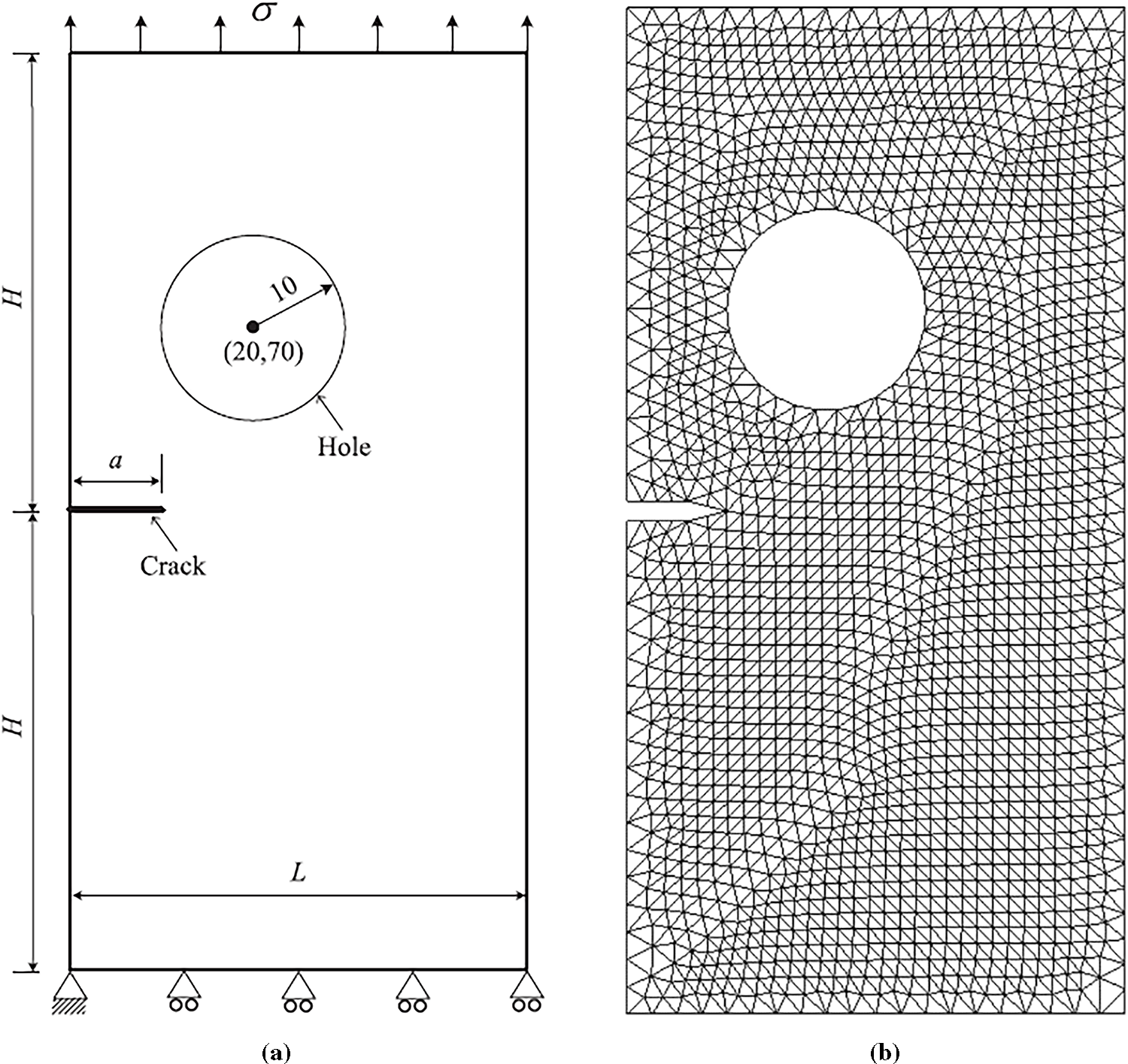
Figure 4: (a) Geometrical representation of a plate with an edge crack and a circular hole, (b) Initial mesh
For the purpose of rigorous comparative analysis and validation, the crack growth trajectory predicted by the present study’s simulations (Fig. 5a) was benchmarked against results obtained from two well-established numerical techniques: the Multi-scale Cell-based Meshless Method (MCMM), as documented by [43] (Fig. 5b), and the Virtual Node Extended Finite Element Method (VNXFEM), as presented in [44], (Fig. 5c). This comparative approach is paramount for substantiating the accuracy, reliability, and general applicability of the developed program in simulating complex fracture mechanics problems. The simulations conducted within this study consistently demonstrated a remarkable concordance between the predicted crack growth trajectories and the findings reported in the independent studies utilizing MCMM [43] and VNXFEM [44]. This strong agreement serves as compelling evidence of the robustness and predictive capability of the developed program. The congruence across different methodologies, each with its unique theoretical underpinnings and computational advantages, significantly enhances the confidence in the obtained results. The visual comparison of these crack growth paths, highlighting the close alignment between the present study’s results and those from [43] and [44], is comprehensively illustrated in Fig. 4.

Figure 5: Crack growth path, (a) Present study, (b) Numerical results [43], and (c) Numerical results [44]
4.2 Plate with Central Hole and Three Edge Cracks
This study investigates the complex phenomena of non-planar multiple crack initiation and growth within a metallic plate featuring a central circular hole and three pre-existing cracks as illustrated in Fig. 6 with its initial mesh. The specimen is subjected to uniaxial cyclic loading, a common scenario in engineering components, to understand the interplay between applied stress, geometric discontinuities, and material response. The primary objective is to analyze the propagation behavior of these interacting cracks, particularly focusing on the influence of stress intensity factors (SIFs) and their impact on crack path deviation.

Figure 6: Geometrical representation of the plate with central hole and three edge cracks (left), and initial mesh (right)
The boundary conditions and loading details are critical for understanding the stress distribution within the specimen. The plate is subjected to cyclic loading with a controlled displacement of −0.005 mm, applied at the base to induce tensile stress in the upper region. This controlled displacement simulates real-world fatigue scenarios where components experience repeated stress cycles.
The material chosen for this investigation is Aluminum 7075, a high-strength aluminum alloy widely used in aerospace and structural applications due to its excellent mechanical properties. Specifically, Al-7075 exhibits a high strength-to-weight ratio, good fatigue resistance, and toughness. For the purpose of this study, the elastic modulus of Al-7075 is taken as 72 GPa, and its Poisson’s ratio is 0.33. The plate thickness is maintained at 3 mm to ensure plane stress conditions, simplifying the analytical and numerical modeling of crack behavior.
Fig. 7a,b compares the predicted crack growth paths from the current study (with and without mesh) to numerical results obtained by Dündar and Ayhan [45] using FEM. This is further validated against Judt and Ricoeur’s [46] findings, which utilized the remote contour interaction integrals method, as shown in Fig. 7c. The close agreement across these results underscores the validity of the present study’s methodology and observations.

Figure 7: Comparison of predicted crack growth paths (a) Present study with mesh, (b) Present study without mesh, (c) Numerical results of [45,46]
In scenarios involving multiple cracks, the propagation sequence is dictated by the SIF values. Based on Fig. 7, crack 3 is predicted to propagate first, followed by crack 2, and finally crack 1. This sequential propagation highlights the dynamic nature of multi-crack systems, where the evolution of SIFs at each crack tip determines the overall fracture process.
As depicted in Fig. 7, the eccentricity of the cracks induces significant shear stress, leading to the dominance of Mode II SIFs. This prevalence of KII is directly responsible for the observed deviation of crack propagation paths from the initial horizontal plane. A key finding is that the close vertical proximity between the second and third cracks results in elevated SIFs within this localized region, surpassing those observed around the first crack. Consequently, the second and third cracks exhibit a more rapid propagation rate compared to the first crack, which advances at a comparatively slower pace. A critical observation from the study is the faster growth rate of the second and third cracks compared to the first. This is attributed to the smaller vertical distance between them, leading to higher localized SIFs in their vicinity. Conversely, the effect of the load on crack 1 is less pronounced compared to the other two cracks, and the hole’s influence on its direction is minimal. Consequently, crack 1 propagates in a direction away from the hole’s vicinity, extending up to 15 mm. This emphasizes the importance of crack interaction in multi-crack systems, where the stress fields of adjacent cracks can significantly influence each other’s propagation behavior. To ensure a valid comparison for all three cracks, regardless of their length, the crack increments in the current analyses were adjusted to match those in Ref. [45]. Accordingly, the Equivalent Stress Intensity Factors (SIFs) are calculated using Eq. (3) and compared to the results obtained by Ref. [45], as shown in Fig. 8. This comparison demonstrates good agreement.

Figure 8: Comparison of equivalent stress intensity factors
4.3 Compact Tension Shear Specimen with Different Loading Angle
A Compact Tension Shear (CTS) specimen with dimensions of 90 mm (width) × 148 mm (height) × 15 mm (thickness) is depicted in Fig. 9a. A pre-existing crack, measuring 45 mm in length, is incorporated along the specimen’s height. Furthermore, each end of the specimen features six circular holes, each with a radius of 7 mm. These holes are strategically positioned such that the distance between opposing hole centers is 27 mm. The material properties of the specimen are, Young’s modulus of 192 GPa, Poisson’s ratio of 0.27, Paris law coefficient (C) of 4.051 × 10⁻⁸ and a Paris law exponent (m) of 2.348. The boundary conditions applied in the finite element model accurately simulate those of the loading device described by Richard and Benits [47] as shown in Fig. 9b. Two distinct sets of boundary conditions are applied:

Figure 9: (a) CTS Specimen Geometry and Boundary Conditions, (b) The loading device for applying various loading angles, (c) The initial generated mesh
1. Upper Holes: The first set of boundary conditions, applied at the upper holes, involves three external forces: F1, F2, and F3. These forces are mathematically defined by the following expressions, as detailed in references [48]:
As illustrated in Fig. 9a, c and b are length parameters equal to 54 mm, and α is defined as the loading angle.
2. Lower Holes: The second set of boundary conditions utilizes kinematic constraints to secure the lower holes, thereby replicating the effect of structural pins at their respective centers.
The finite element analysis was conducted with a constant applied load of 14 kN and a stress ratio of 0.1, while the loading angle was varied across 30°, 45°, and 60°. The initial generated mesh is shown in Fig. 9c.
The predictive capability of the developed program was rigorously tested by comparing its results with established experimental data. As illustrated in Figs. 10 and 11, the crack growth directions simulated by the analysis show a strong correlation with the physical experiments conducted by Sajith et al. [49]. This comparison, performed across a range of loading angles (30°, 45°, and 60°), serves as a critical validation of the methodology, demonstrating its effectiveness in accurately modeling fracture behavior under varied stress conditions.

Figure 10: Predicted crack growth path: (a) 30° loading angle, (b) 45° loading angle, and (c) 60° loading angle

Figure 11: Experimental crack growth path: (a) 30° loading angle [49], (b) 45° loading angle [49], and (c) 60° loading angle [49]
This investigation estimated the number of cycles for various loading angles (30°, 45°, and 60°), and these estimations align significantly with experimental results for mixed-mode (I/II) loading reported by [49] as illustrated in Figs. 12–14. The present study’s predicted fatigue life cycles demonstrated high fidelity, with a maximum relative error of no more than 1% compared to the experimental data reported by Sajith et al. [49].

Figure 12: Simulated vs. experimental [49] fatigue life at 30°
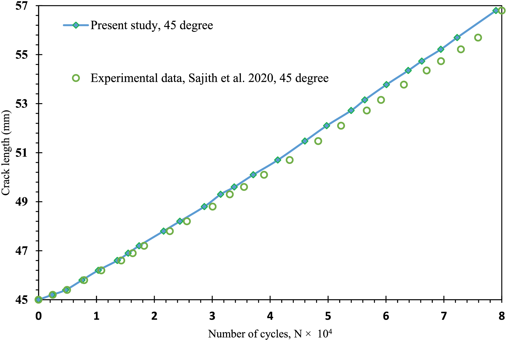
Figure 13: Simulated vs. experimental [49] fatigue life at 45°

Figure 14: Simulated vs. experimental [49] fatigue life at 60°
The proposed adaptive finite element methodology demonstrates robust performance in 2D linear elastic fatigue crack growth simulation, primarily due to its algorithmic transparency, accurate adaptive meshing with specialized crack tip elements, and computational efficiency achieved by optimizing mesh refinement. The integration of a consistent transfer algorithm and crack relaxation method further ensures solution stability during incremental crack propagation. However, certain limitations were taken into account when developing the program:
• Mesh Distortion: While adaptive remeshing is employed, complex crack paths or large deformations can lead to mesh distortion, potentially affecting accuracy and simulation stability. The current implementation includes element shape checks and criteria for remeshing to mitigate this limitation.
• Convergence Problems: Convergence issues can arise from the non-linear nature of crack growth and data transfer during remeshing. This framework addresses this through a consistent transfer algorithm using advanced interpolation and a crack relaxation method to stabilize solutions.
This paper presents a comprehensive finite element methodology for simulating two-dimensional fatigue crack growth under linear elastic conditions, leveraging a custom program developed in Fortran 95. The approach is built upon a robust computational framework that integrates several advanced techniques to ensure both accuracy and efficiency. Key features of the methodology include:
• Adaptive Mesh Generation: The system employs automatic adaptive mesh refinement, which strategically increases mesh density in critical areas, such as the vicinity of the crack front and regions with high stress gradients. This selective refinement optimizes computational resources while maintaining high precision.
• Accurate Stress Calculation: To accurately capture the stress singularity at the crack tip, specialized singular crack tip elements are utilized. The stress intensity factors (SIFs), which govern crack propagation, are calculated using the reliable displacement extrapolation technique.
• Crack Growth Prediction: The direction of crack propagation is determined using the maximum tangential stress criterion. The rate of growth and the fatigue life of the component are then predicted based on the Paris law, which relates the crack growth rate to the stress intensity factor range.
• Stable Simulation: A consistent transfer algorithm and a crack relaxation method are implemented to ensure the stability and reliability of the solution as the crack propagates through the material.
The effectiveness and accuracy of this integrated approach were validated through three distinct case studies: edge-cracked plates containing a circular hole, plate with central hole and three edge cracks, and a compact tension shear specimen with different loading angle. In addition, the program’s validity and accuracy are corroborated by numerous published articles in the existing literature. The results from these studies, which utilize the developed program, show a strong correlation with both experimental data and other numerical results. This confirms the methodology’s capability to accurately predict physical crack paths and component fatigue lives. Ultimately, this work provides a powerful and validated computational tool for engineering applications, particularly in the fields of damage-tolerant design, fitness-for-service assessments, and failure analysis. By providing a clear and detailed procedure, the developed program serves as a valuable guide for researchers, offering a foundational blueprint that can help them build their own customized simulation tools for fracture mechanics analysis. This makes the work a powerful resource for engineering applications in damage-tolerant design, fitness-for-service assessment, and failure analysis.
Acknowledgement: Not applicable.
Funding Statement: The authors gratefully acknowledge the funding of the Deanship of Graduate Studies and Scientific Research, Jazan University, Saudi Arabia, through Project number: JU-20250230-DGSSR-RP-2025.
Author Contributions: Conceptualization, Abdulnaser M. Alshoaibi; Methodology, Yahya Ali Fageehi; Software, Abdulnaser M. Alshoaibi; Validation, Abdulnaser M. Alshoaibi; Formal analysis, Yahya Ali Fageehi and Abdulnaser M. Alshoaibi; Investigation, Yahya Ali Fageehi and Abdulnaser M. Alshoaibi; Resources, Yahya Ali Fageehi and Abdulnaser M. Alshoaibi; Data curation, Abdulnaser M. Alshoaibi; Writing—original draft, Abdulnaser M. Alshoaibi; Writing—review & editing, Abdulnaser M. Alshoaibi; Visualization, Abdulnaser M. Alshoaibi; Supervision, Yahya Ali Fageehi and Abdulnaser M. Alshoaibi; Project administration, Yahya Ali Fageehi and Abdulnaser M. Alshoaibi; Funding acquisition, Yahya Ali Fageehi and Abdulnaser M. Alshoaibi. All authors reviewed the results and approved the final version of the manuscript.
Availability of Data and Materials: The original contributions presented in this study are included in the article. Further inquiries can be directed to the corresponding author.
Ethics Approval: This study did not involve any human participants, animals, or sensitive personal data. Therefore, ethics approval was not required in accordance with institutional and national guidelines.
Conflicts of Interest: The authors declare no conflicts of interest to report regarding the present study.
Appendix A Detailed Subroutine Descriptions
1. INPUT: This subroutine gathers the necessary data for solving linear elastic fracture mechanics problems using the finite element method. This includes information on control, geometry, boundary conditions, and material properties, as well as the specific method for determining stress intensity factors.
2. NODEXY: Generates coordinates for nodes located at the midpoint of an element’s side.
3. GAUSSQ: Creates the necessary data for Gaussian quadrature integration.
4. SFR2: Evaluates the shape functions for an element.
5. JACOB2: Calculates the Jacobian matrix.
6. BMATPS: Computes the strain-displacement matrix (B matrix) for 2D plane problems.
7. MODPS: Determines the material property matrix (D matrix) for 2D plane problems.
8. DBE: Performs the matrix multiplication of D and B.
9. FRONT: Solves the system of linear equations using the frontal method.
10. STIFPS: Calculates the stiffness matrices for individual elements.
11. LOADPS: Determines the nodal forces for each element in a 2D plane problem.
12. STREPS: Evaluates the stresses within each element.
13. BOUND: Organizes the boundary condition (fixity) data into a vector format.
14. CHECK1: A subroutine for diagnosing errors in the input data.
15. ECHO: A data echo subroutine that lists all remaining data cards after an error has been detected by the diagnostic subroutines (CHECK1 or CHECK2).
16. CHECK2: A subroutine used for diagnosing errors in the input data.
17. T1PEL: This subroutine identifies the quarter-point nodes specifically for the elements located at the crack tip.
18. SIFCALC1: Calculates the stress intensity factors by applying the displacement extrapolation method.
19. SIFCALC2: Calculates the stress intensity factors using the J-integral method.
20. PREST: This subroutine’s function is to initialize the values of variables used within the program.
21. ZERO: Sets the values of various arrays in the program to zero. This is necessary for arrays that accumulate data during incremental and iterative processes, ensuring they start from a clean state.
22. STIFFP: This subroutine calculates the stiffness matrix for each element individually, and its method differs from the linear elastic approach.
23. OUTPUT: Manages the output of results, with the frequency of output being controlled by user-defined parameters.
24. CONVER: Monitors the convergence of the iterative process in a non-linear solution to determine if it has reached a stable result.
25. INCREM: This subroutine is responsible for increasing the applied loads or any specified displacements based on the load factors provided in the input data.
26. CRACPRO: Crack propagation subroutine.
27. ADVFROM: Generates the mesh using the advancing front method
28. ADDROSE: Patches singular elements around the crack tip.
29. ADVFROM: Generates the mesh using the advancing front method.
30. BMSTRUC: Creates a structured background mesh.
31. STRESSES: Evaluates unsmoothed and smoothed stress fields.
32. PROCESS: Solves the system using an iterative Preconjugate Gradient method.
33. ESTIMAT: Evaluates error for h-type adaptive mesh refinement.
34. RESULTS: Writes results for external post-processing tools
References
1. Salvati E. Evaluating fatigue onset in metallic materials: problem, current focus and future perspectives. Int J Fatigue. 2024;188(1):108487. doi:10.1016/j.ijfatigue.2024.108487. [Google Scholar] [CrossRef]
2. Robles JM, Vasco-Olmo JM, Cruces AS, Diaz FA, James MN, Lopez-Crespo P. Fatigue crack characterisation in 2024-T351 aluminium alloy through SEM observation combined with the CJP model. Int J Fatigue. 2023;166(2):107279. doi:10.1016/j.ijfatigue.2022.107279. [Google Scholar] [CrossRef]
3. Bhaumik SK, Sujata M, Venkataswamy MA. Fatigue failure of aircraft components. Eng Fail Anal. 2008;15(6):675–94. doi:10.1016/j.engfailanal.2007.10.001. [Google Scholar] [CrossRef]
4. Natarajan S, Ooi ET. Fatigue crack growth in functionally graded materials using an adaptive phase field method with cycle jump scheme. Eng Fract Mech. 2024;312(35):110573. doi:10.1016/j.engfracmech.2024.110573. [Google Scholar] [CrossRef]
5. Jaccon A, Prabel B, Molnár G, Bluthé J, Gravouil A. Adaptive mesh refinement and cycle jumps for phase-field fatigue fracture modeling. Finite Elem Anal Des. 2023;224(582–593):104004. doi:10.1016/j.finel.2023.104004. [Google Scholar] [CrossRef]
6. Hu X, Li S. A stress-intensity-factor-driven phase field modeling of mixed mode fracture. Comput Meth Appl Mech Eng. 2025;443(1):118058. doi:10.1016/j.cma.2025.118058. [Google Scholar] [CrossRef]
7. Wang Y, Chao L, Chen J, Jiang S. Fatigue crack propagation law of corroded steel box girders in long span bridges. Comput Model Eng Sci. 2024;140(1):201–27. doi:10.32604/cmes.2024.046129. [Google Scholar] [CrossRef]
8. Thiruvannamalai M, Venkatesan PV, Chellapandian M. Fatigue life predictions using a novel adaptive meshing technique in non-linear finite element analysis. Buildings. 2024;14(10):3063. doi:10.3390/buildings14103063. [Google Scholar] [CrossRef]
9. Zhang T, Hirshikesh, Yu T, Ding J, Natarajan S. Low-cycle fatigue crack growth in brittle materials: adaptive phase-field modeling with variable-node elements. Comput Meth Appl Mech Eng. 2024;425(8):116917. doi:10.1016/j.cma.2024.116917. [Google Scholar] [CrossRef]
10. Habashneh M, Movahedi Rad M. Optimizing structural topology design through consideration of fatigue crack propagation. Comput Meth Appl Mech Eng. 2024;419(1):116629. doi:10.1016/j.cma.2023.116629. [Google Scholar] [CrossRef]
11. Lu R, Li KS, Wang J, Yang J, Zhang XC, Tu ST. Understanding the small creep-fatigue crack growth mechanism of polycrystalline alloy based on crystal plasticity and extended finite element method. Eng Fract Mech. 2024;306:110172. doi:10.1016/j.engfracmech.2024.110172. [Google Scholar] [CrossRef]
12. Chen Z, Dai Y, Liu Y. Structural fatigue crack propagation simulation and life prediction based on improved XFEM-VCCT. Eng Fract Mech. 2024;310(8):110519. doi:10.1016/j.engfracmech.2024.110519. [Google Scholar] [CrossRef]
13. Sedmak A, Grbović A, Gubeljak N, Sedmak S, Budimir N. Numerical simulation of fatigue crack growth and fracture in welded joints using XFEM—a review of case studies. Materials. 2024;17(22):5531. doi:10.3390/ma17225531. [Google Scholar] [PubMed] [CrossRef]
14. Xiong Z, Zhu C, Yang Y, Lin T, Li R. XFEM-based study of fatigue crack propagation in rocket deflector troughs under coupled high-temperature and impact conditions. J Mar Sci Eng. 2024;12(2):207. doi:10.3390/jmse12020207. [Google Scholar] [CrossRef]
15. Tian T, Chen C, He L, Wei H. Adaptive finite element method for phase field fracture models based on recovery error estimates. J Comput Appl Math. 2026;472(3):116732. doi:10.1016/j.cam.2025.116732. [Google Scholar] [CrossRef]
16. Qiu S, Duan Q, Shao Y, Chen S, Yao W. Adaptive finite element method for hybrid phase-field modeling of three-dimensional cracks. Eng Fract Mech. 2022;271(1-2):108636. doi:10.1016/j.engfracmech.2022.108636. [Google Scholar] [CrossRef]
17. Alshoaibi AM. Comprehensive comparisons of two-and three-dimensional numerical estimation of stress intensity factors and crack propagation in linear elastic analysis. Int J Integr Eng. 2019;11(6):45–52. doi:10.30880/ijie.2019.11.06.006. [Google Scholar] [CrossRef]
18. Ali Fageehi Y. Two- and three-dimensional numerical investigation of the influence of holes on the fatigue crack growth path. Appl Sci. 2021;11(16):7480. doi:10.3390/app11167480. [Google Scholar] [CrossRef]
19. Malaysia UK, Alshoaibi AA, Mohd Ihsan AKA. Evaluation of stress intensity factor using displacement correlation techniques. J Kejuruteraan. 2008;20(1):75–81. doi:10.17576/jkukm-2008-20-07. [Google Scholar] [CrossRef]
20. Alshoaibi AM, Hadi MSA, Ariffin AK. An adaptive finite element procedure for crack propagation analysis. J Zhejiang Univ—Sci A. 2007;8(2):228–36. doi:10.1631/jzus.2007.a0228. [Google Scholar] [CrossRef]
21. Tolga Duran E, Demiral M. Comparing and validating the numerical modeling of spot-welded fatigue failure using FEM and XFEM methods for HCF. Eng Fail Anal. 2024;158(2):108049. doi:10.1016/j.engfailanal.2024.108049. [Google Scholar] [CrossRef]
22. Bergara A, Dorado JI, Martin-Meizoso A, Martínez-Esnaola JM. Fatigue crack propagation in complex stress fields: experiments and numerical simulations using the Extended Finite Element Method (XFEM). Int J Fatigue. 2017;103(1–3):112–21. doi:10.1016/j.ijfatigue.2017.05.026. [Google Scholar] [CrossRef]
23. Li B, Peco C, Millán D, Arias I, Arroyo M. Phase-field modeling and simulation of fracture in brittle materials with strongly anisotropic surface energy. Int J Numer Meth Eng. 2015;102(3–4):711–27. doi:10.1002/nme.4726. [Google Scholar] [CrossRef]
24. Waseem S, Erdogan C, Yalçinkaya T. Phase field modeling of fatigue crack growth retardation under single cycle overloads. Int J Fatigue. 2024;179(582–593):108064. doi:10.1016/j.ijfatigue.2023.108064. [Google Scholar] [CrossRef]
25. Alshoaibi AM. Finite element procedures for the numerical simulation of fatigue crack propagation under mixed mode loading. Struct Eng Mech. 2010;35(3):283–99. doi:10.12989/sem.2010.35.3.283. [Google Scholar] [CrossRef]
26. Sikirica A, Grbčić L, Alvir M, Kranjčević L. Computational efficiency assessment of adaptive mesh refinement for turbulent jets in crossflow. Mathematics. 2022;10(4):620. doi:10.3390/math10040620. [Google Scholar] [CrossRef]
27. Khoei AR, Azadi H, Moslemi H. Modeling of crack propagation via an automatic adaptive mesh refinement based on modified superconvergent patch recovery technique. Eng Fract Mech. 2008;75(10):2921–45. doi:10.1016/j.engfracmech.2008.01.006. [Google Scholar] [CrossRef]
28. Xu W, Jiang D, Zhang C, Li H, Qiang S, Li Y, et al. An adaptive mesh refinement strategy for 3D phase modeling of brittle fracture. Eng Fract Mech. 2023;284(1–4):109241. doi:10.1016/j.engfracmech.2023.109241. [Google Scholar] [CrossRef]
29. Phongthanapanich S, Dechaumphai P. Adaptive Delaunay triangulation with object-oriented programming for crack propagation analysis. Finite Elem Anal Des. 2004;40(13–14):1753–71. doi:10.1016/j.finel.2004.01.002. [Google Scholar] [CrossRef]
30. Zienkiewicz OC, Taylor RL, Zhu JZ. The finite element method: its basis and fundamentals. 7th ed. Amsterdam, The Netherlands: Elsevier; 2013. [Google Scholar]
31. Lo DS. Finite element mesh generation. Boca Raton, FL, USA: CRC Press; 2014. [Google Scholar]
32. Zienkiewicz OC, Zhu JZ. The superconvergent patch recovery and a posteriori error estimates. Part 2: error estimates and adaptivity. Int J Numer Meth Eng. 1992;33(7):1365–82. doi:10.1002/nme.1620330703. [Google Scholar] [CrossRef]
33. Borouchaki H, Frey PJ. Simplification of surface mesh using Hausdorff envelope. Comput Meth Appl Mech Eng. 2005;194(48–49):4864–84. doi:10.1016/j.cma.2004.11.016. [Google Scholar] [CrossRef]
34. Quadros WR, Owen SJ, Brewer ML, Shimada K. Finite element mesh sizing for surfaces using skeleton. In: Proceedings of the 13th International Meshing Roundtable; 2004 Sep 19–22; Williamsburg, VA, USA. p. 389–400. [Google Scholar]
35. Edelsbrunner H. Triangulations and meshes in computational geometry. Acta Numer. 2000;9:133–213. doi:10.1017/s0962492900001331. [Google Scholar] [CrossRef]
36. Boissonnat JD, Oudot S. Provably good sampling and meshing of surfaces. Graph Models. 2005;67(5):405–51. doi:10.1016/j.gmod.2005.01.004. [Google Scholar] [CrossRef]
37. Alshoaibi AM, Bashiri AH. Adaptive finite element modeling of linear elastic fatigue crack growth. Materials. 2022;15(21):7632. doi:10.3390/ma15217632. [Google Scholar] [PubMed] [CrossRef]
38. Irwin GR. Analysis of stresses and strains near the end of a crack traversing a plate. J Appl Mech. 1957;24(3):361–4. doi:10.1115/1.4011547. [Google Scholar] [CrossRef]
39. Westergaard HM. Bearing pressures and cracks: bearing pressures through a slightly waved surface or through a nearly flat part of a cylinder, and related problems of cracks. J Appl Mech. 1939;6(2):A49–53. doi:10.1115/1.4008919. [Google Scholar] [CrossRef]
40. Yan X, Du S, Zhang Z. Mixed-mode fatigue crack growth prediction in biaxially stretched sheets. Eng Fract Mech. 1992;43(3):471–5. doi:10.1016/0013-7944(92)90115-U. [Google Scholar] [CrossRef]
41. Bjørheim F. Practical comparison of crack meshing in ANSYS mechanical APDL 19.2 [master’s thesis]. Stavanger, Norway: University of Stavanger; 2019. [Google Scholar]
42. ANSYS. Academic research mechanical, release 19.2, help system. In: Coupled field analysis guide. Canonsburg, PA, USA: ANSYS, Inc.; 2020. [Google Scholar]
43. Cai Y, Sun P, Zhu H, Rabczuk T. A mixed cover meshless method for elasticity and fracture problems. Theor Appl Fract Mech. 2018;95:73–103. doi:10.1016/j.tafmec.2018.01.011. [Google Scholar] [CrossRef]
44. Kumar S, Singh IV, Mishra BK, Rabczuk T. Modeling and simulation of kinked cracks by virtual node XFEM. Comput Meth Appl Mech Eng. 2015;283(11):1425–66. doi:10.1016/j.cma.2014.10.019. [Google Scholar] [CrossRef]
45. Dündar H, Ayhan AO. Non-planar crack growth analyses of multiple cracks in thin-walled structures. Int J Fatigue. 2016;92:596–604. doi:10.1016/j.ijfatigue.2016.02.039. [Google Scholar] [CrossRef]
46. Judt PO, Ricoeur A. Crack growth simulation of multiple cracks systems applying remote contour interaction integrals. Theor Appl Fract Mech. 2015;75:78–88. doi:10.1016/j.tafmec.2014.11.001. [Google Scholar] [CrossRef]
47. Richard HA, Benitz K. A loading device for the creation of mixed mode in fracture mechanics. Int J Fract. 1983;22(2):R55–8. doi:10.1007/BF00942726. [Google Scholar] [CrossRef]
48. Richard H. Fracture predictions for cracks exposed to superimposed normal and shear stresses. 1st ed. Duesseldorf, Germany: VDI-Verl; 1985. [Google Scholar]
49. Sajith S, Shukla SS, Murthy KSRK, Robi PS. Mixed mode fatigue crack growth studies in AISI 316 stainless steel. Eur J Mech A/Solids. 2020;80:103898. doi:10.1016/j.euromechsol.2019.103898.s. [Google Scholar] [CrossRef]
Cite This Article
 Copyright © 2025 The Author(s). Published by Tech Science Press.
This work is licensed under a Creative Commons Attribution 4.0 International License , which permits unrestricted use, distribution, and reproduction in any medium, provided the original work is properly cited.
 Downloads
 Citation Tools