
 Submit a Paper
 Propose a Special lssue
 Open Access
ARTICLE

Numerical Modelling of Oblique Wave Interaction with Dual Curved-LEG Pontoon Floating Breakwaters
1 Department of Mathematics, School of Advanced Sciences, Vellore Institute of Technology, Vellore, 632014, India
2 Scientific Computing Group, University of Salamanca, Plaza de la Merced, Salamanca, 37008, Spain
3 Department of Applied Mathematics, Escuela Politécnica Superior de Zamora, University of Salamanca, Campus Viriato, Zamora, 49022, Spain
* Corresponding Authors: Chandru Muthusamy. Email: ; Higinio Ramos. Email:
(This article belongs to the Special Issue: Scientific Computing and Its Application to Engineering Problems)
Computer Modeling in Engineering & Sciences 2025, 145(2), 2017-2038. https://doi.org/10.32604/cmes.2025.071958
Received 16 August 2025; Accepted 17 October 2025; Issue published 26 November 2025
 View Full Text
 Download PDF
Abstract
This study investigates the performance of dual curved-leg pontoon floating breakwaters in finite water depth under the assumption of linear wave theory. The analysis is carried out for four different models of curved-leg geometries, which are combinations of convex and concave shapes. The models are classified as follows. Model-1: Seaside and leeside face concave, Model-2: Seaside and leeside face convex, Model-3: Seaside face convex and leeside face concave, and Model-4: Seaside face concave and leeside face convex. The Boundary Element Method is utilized in order to find a solution to the associated boundary value problem. The numerical results are validated against existing analytical and experimental data. Further, the study examines the wave reflection, wave transmission, and the hydrodynamic forces acting on the structure for different values of waves and structural parameters. Overall, the different dual curved-leg pontoon breakwaters are more effective, reducing wave transmission by over 15% and increasing wave reflection by more than 5% compared to traditional models. The study shows that the wave reflected by Model 1 significantly increased and attenuated the wave transmission relative to other models. The study found that the height of the curved-leg of Model 1 plays a critical role in blocking waves and redirecting the flow. More precisely, the present analysis concludes that the hydrodynamic performance of Model-1 presents an optimized breakwater design that outperforms the proposed models.Keywords
Over the past few decades, the gradual rise in sea levels has significantly impacted coastlines and communities in various coastal nations. Coupled with this phenomenon, the accelerated urbanization and expansion of human activities in countries such as Singapore, Japan, and the Netherlands have placed substantial demands on land resources [1–2]. To address these challenges, the utilization of marine space through the development of very large floating structures along coastlines and in harbors has emerged as a promising solution. These very large floating structures, which include applications such as bridges, airports, offshore platforms, wave energy systems, military installations, aquaculture protection structures, and ship navigation aids, offer distinct advantages such as reduced construction costs, efficient water exchange, and ease of construction compared to traditional bottom-standing breakwaters [3–6]. However, despite these advantages, Very Large Floating Structures (VLFS) are vulnerable to extreme ocean conditions such as storm waves and tsunamis. Therefore, it is essential to design new hybrid VLFS models capable of improving hydrodynamic performance and ensuring long-term structural safety.
Many floating breakwaters have been proposed to improve hydrodynamic performance. According to their structural features and applications, floating breakwaters are categorized into various configurations, such as box-type, pontoon-type, frame-type, mat-type, tethered float-type, and horizontal plate-type [7]. Noteworthy advancements in this domain have been reported in the literature. For instance, Mei and Black [8] explored the wave reflection and transmission coefficient of rectangular obstacles employing the eigenfunction expansion approach, with their findings corroborated through experimental and analytical comparisons. Williams and Abul-Azm [9] studied a twin pontoon leg floating breakwater using the eigenfunction expansion approach. Neelamani and Rajendran [10] investigated a T-type floating breakwater, demonstrating that an increase in the vertical sectional area enhanced wave reflection and overall wave attenuation. Subsequently, Esmaeel [11] provided numerical insights into the same breakwater type, highlighting its lower wave transmission compared to rectangular designs and emphasizing the role of draft in wave attenuation. Pena et al. [12] evaluated the hydrodynamic characteristics of a rectangular structure with a slotted barrier, reporting improved wave transmission coefficients. Masoudi et al. [13] carried out a detailed parametric investigation into the hydrodynamic behavior of a two-legged rectangular floating breakwater. Their findings indicated that this configuration offered superior performance compared to conventional rectangular floating breakwaters, and that the legs play an efficient role in the structural response. Similarly, Ruol et al. [14] and Sharma et al. [15] investigated
Complex structural geometries have attracted significant attention due to their capacity to improve wave attenuation, blocking efficacy, and energy dissipation, thereby offering enhanced solutions for coastal defense and offshore stability [17–19]. Jain et al. [20] introduced floating breakwaters with arc-shaped wings and opening-pass structures, reporting 8.2%–17.8% lower transmission coefficients compared to traditional designs. Hussein et al. [21] conducted both experimental and numerical analyses on curved breakwaters, comparing convex and concave semi-circular configurations, and found that concave configurations provided superior energy dissipation. Further, El Saie et al. [22] demonstrated the hydrodynamic efficiency of a structure with a curved design, noting that increased concavity enhances energy absorption with respect to wave height and steepness. He et al. [23] studied single-wing floating breakwaters using the matching eigenfunction expansion method to analyze convex, concave, and inclined wing geometries. It was noted that the wing model reduced wave transmission compared to the rectangular structure and the heave plate. The authors later extended the study to investigate double-wing floating breakwaters [24]. They found that the double-wing floating breakwater effectively blocked the waves and dissipated the wave energy compared to the single-wing floating breakwater. Therefore, the effects of wave blocking and energy dissipation mainly affects the presence of a dual-curved leg floating structure. For this reason, the present study focuses on the dual-curved floating breakwaters.
Recent advancements in the technology of floating structures have facilitated the emergence of VLFS, which are currently being investigated for a broader range of marine applications. The potential applications of such large floating structures extend far beyond conventional uses such as airports, bridges, or platforms for sea-to-land transportation. Research by various authors, including [25–28], emphasizes their versatility. For instance, Lee et al. [29] analyzed rectangular floating platforms integrated with tuned liquid column dampers, demonstrating an effective reduction in wave forces. Wang and Yung [30] examined a pontoon-type very large floating breakwater incorporating hydro-elastic plates, highlighting their capacity to mitigate wave-induced responses on platforms. Sun et al. [31] studied a pontoon-type floating bridge under regular wave conditions and discovered that nonlinear hydroelastic effects greatly impact bending moments, which must be considered in design. Numerical investigations into the hydrodynamic properties of coastal bridge decks by Qu et al. [32] revealed that wave loads on bridge decks increase with wave heights. Experimental studies by Luo et al. [33] examined the impact of freak wave actions and air gap variations on floating platforms, concluding that reduced air gaps increase tether forces. Khan et al. [34] examined a submerged structure placed near a floating dock using the boundary element method. They found that the submerged structure shielded the floating dock. Further, the multi-flat leg attached to a very large floating breakwater was investigated in [35] and [36]. The results revealed that the multi-flat legs protected the floating structure. Moreover, the above studies focused on the elastic plate, separated structures, and flat legs used to protect the very large floating structures. As a novelty contribution, the present study deals with a curved leg directly attached to a floating breakwater, which forms the main focus of the research.
Previous studies have established that structural modifications, such as a single horizontal thick attachment [37] and two-leg extensions [13], can significantly affect the hydrodynamic performance of a rectangular floating breakwater. To the best of the author’s knowledge, no systematic study has investigated rectangular floating breakwaters equipped with curved-leg geometries, despite their potential to enhance wave blocking, flow direction, energy dissipation, and structural resilience. To address this gap, the present study analyzes four novel curved-leg pontoon floating breakwater models with different curvatures and configurations. The objective is to determine which configuration offers the most effective wave attenuation and structural protection, with potential applications in platforms, bridges, and coastal protection systems.
In the present study, the mathematical model for the proposed physical problem is described in Section 2, followed by the presentation of the Boundary Element Method(BEM)-based numerical technique to solve the associated boundary value problem in Section 3. In Section 4, the current study is validated against previously published results, and an analysis of various curved-leg models is carried out. Finally, Section 5 provides concluding remarks and insights derived from the study.
This section presents the mathematical model for oblique wave scattering by dual curved-leg pontoon floating breakwaters, analyzed under the assumptions of small-amplitude linear wave theory. The current study analyzes four different configurations of floating breakwaters. The present problem is formulated in a three-dimensional Cartesian coordinate system with the
Further, assume that the fluid is inviscid and incompressible and that the flow is represented as irrotational. The incident wave travels at an oblique angle
The boundary notations corresponding to those given in Fig. 1 are explained below:
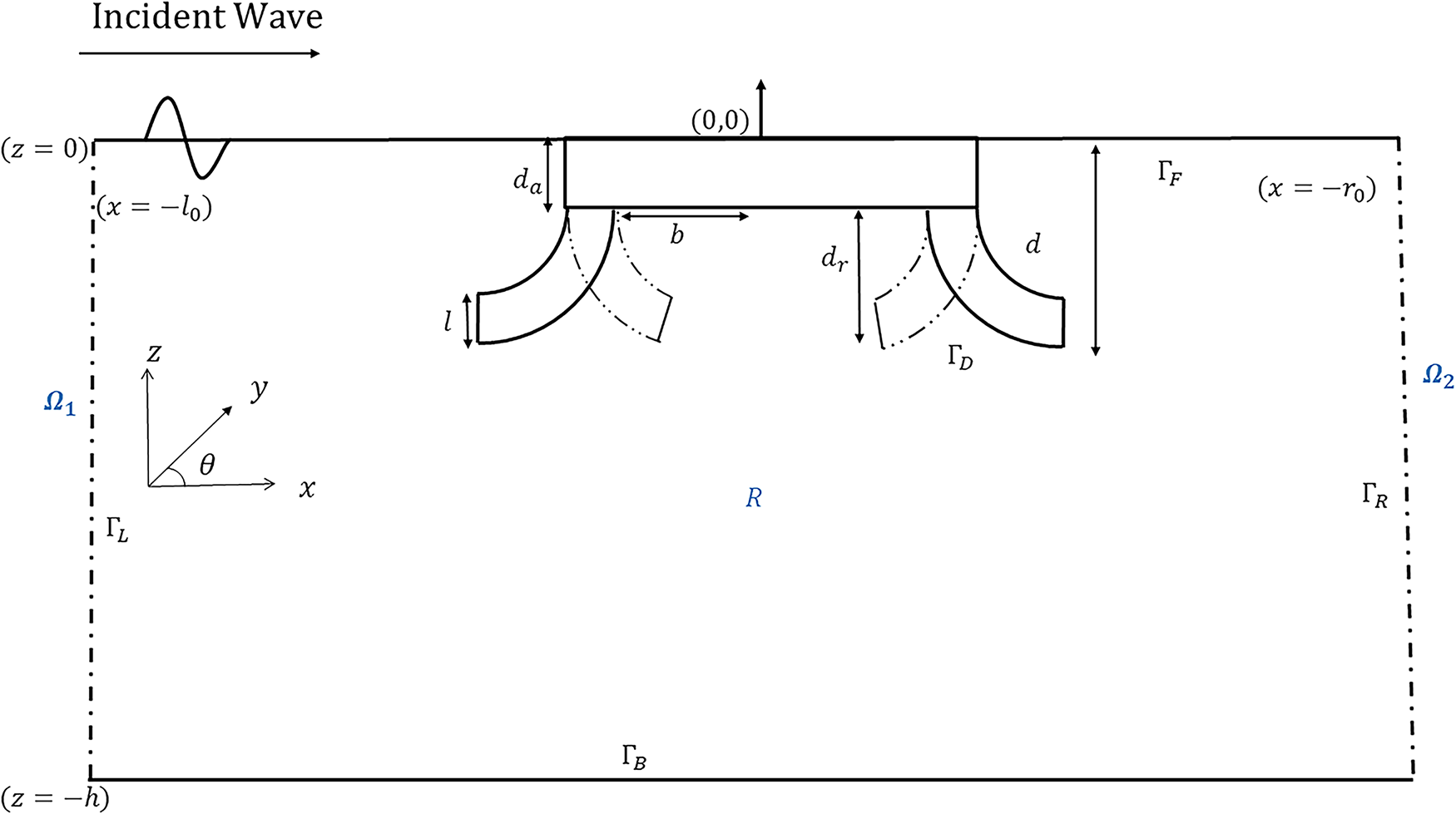
Figure 1: Schematic sketch of dual curved pontoon floating structure: BEM formulation
Model-1:
Model-2:
Model-3:
Model-4:
Further, the impermeable bottom boundary has zero flux as defined by
The free surface is governed by the linearized kinematic and dynamic conditions, which combine to yield the free surface boundary condition as:
where
Subsequently, the far-field conditions are described as
where
In this section, the boundary value problem along with its associated boundary conditions is formulated using the eigenfunction expansion approach for the velocity potential in the unbounded region, and the boundary element method is applied in the bounded region.
3.1 Eigenfunction Expansion Method in the Unbounded Domain
The spatial velocity potential function in the unbounded regions
where
and the dispersion relation is satisfied by
The eigenfunctions
where
The undetermined coefficients
The normal derivatives associated with the potential function are defined as
Substituting the unknown coefficients
where
where
These aforementioned two normal derivatives of the potential function constitute the boundary conditions for the left and right lateral boundaries.
3.2 Boundary Element Method in the Bounded Region
Applying Green’s second identity to the spatial velocity potential
where the fundamental solution G that satisfies the Helmholtz equation
where
Substituting the above expression into (18), we obtain [39]
which gives
Now, let
Finally, it reduces to
The above equation corresponds to the general form of the Bessel equation. Its solution is given by
The modified Bessel fuction of the first kind,
while the modified Bessel function of the second kind,
Further, as the origin
Thus,
Using the divergence theorem, the first term can be expressed as
Consequently, we further deduce that
Next, the second kind of equation is given by
The above expression tends to zero as
Substituting the value of
which is the fundamental solution of the Helmholtz equation, where
Further, the Bessel function of the recurrence formula is employed to determine the normal derivative of G, providing
where
where
To solve the aforementioned boundary integral equation, the region is discretized into a limited number of boundary elements, with assumed values
Here,
when
The elevation of the free surface is represented by
The wave forces exerted on the breakwater are defined by
In this section, the impacts of a floating dual curved-leg pontoon breakwater on surface wave scattering are examined for different physical parameters. The eigenfunction expansion approach is used on semi-infinite regions, and the boundary element method is employed on closed regions, enabling computational efficiency. Throughout the discussion, the following fixed physical parameters are used, unless stated otherwise: water depth
The curved-leg geometry of the floating breakwater satisfies the circular equation:
where
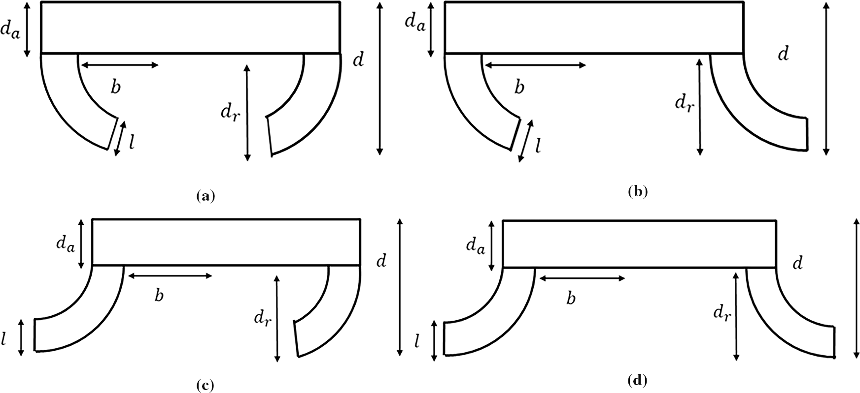
Figure 2: Various types of curved-leg pontoon floating breakwater: (a) Model-1, (b) Model-2, (c) Model-3, (d) Model-4
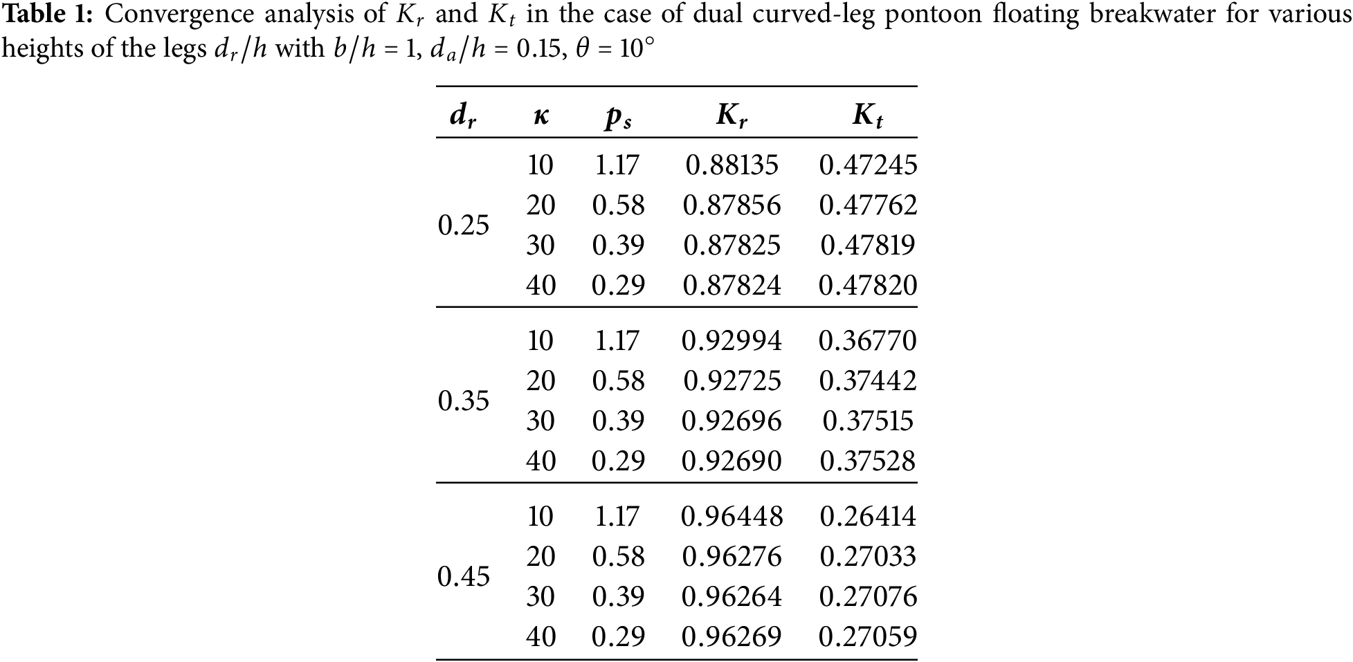
The convergence of the numerical solutions derived via BEM depends on the dimensions of the panels employed to discretize the boundaries in the closed domain. The panel size
where
4.2 Model Validation and Numerical Results on Dual Curved-Leg Pontoon Breakwaters
The present section determines the wave reflection and transmission coefficients employing the boundary element method and compares them with previous research on rectangular structures. As the height of the curved-leg geometries approaches zero, the dual curved-leg pontoon floating structure effectively transforms into a rectangular configuration. Fig. 3a illustrates the reflection coefficient vs. the dimensionless height of the structure
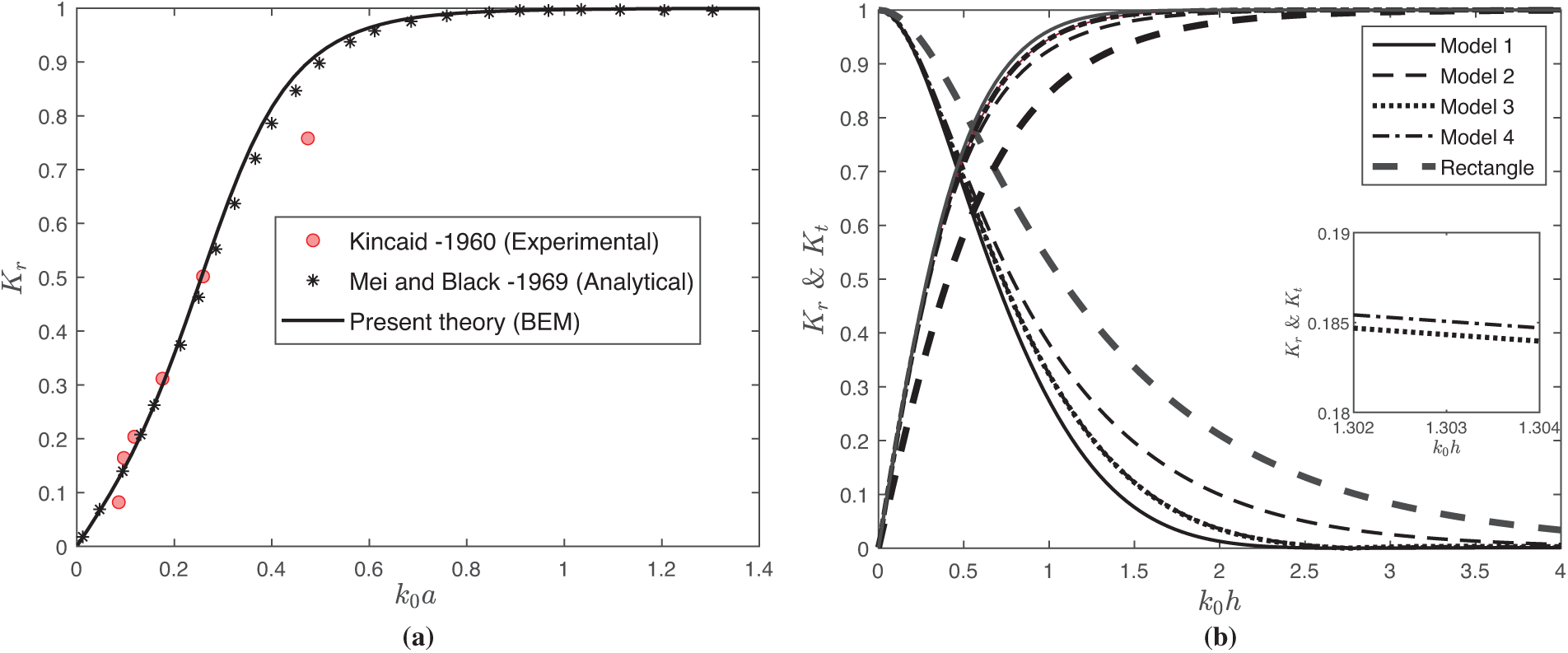
Figure 3: Comparison of
Fig. 3b depicts the wave reflection
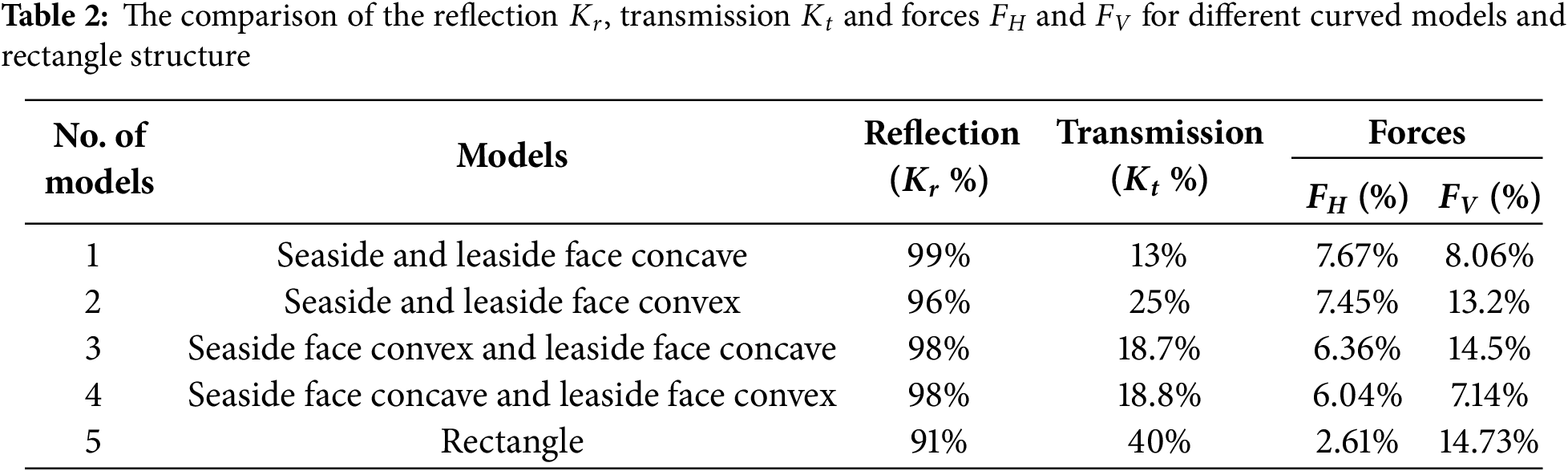
Fig. 4 presents the wave variation of wave-induced forces on the curved-leg pontoon breakwater vs. wave number
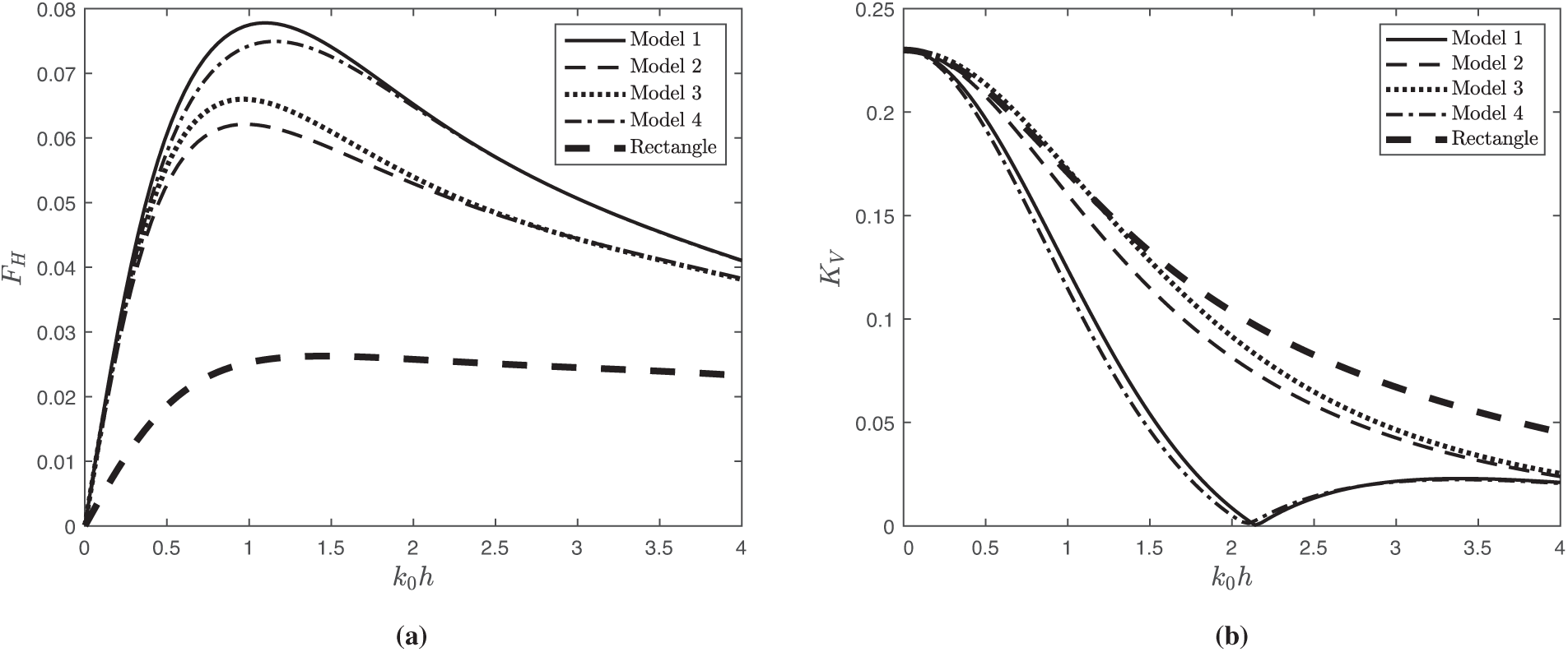
Figure 4: Variation of (a)
Fig. 5 illustrates the distribution of free surface elevation for different models and different heights of the curved-leg geometries. Fig. 5a depicts that the surface elevation of the rectangular model increases on both the seaside and leeside, whereas Model-1 shows a decrease on both sides. This reduction is attributed to the presence of the attached curved-leg pontoons, which increase the wave blocking effect. Furthermore, it is observed that the surface elevation on both the leeside and seaside of the breakwater is lower in Model-1 compared to other models due to the larger area between the legs. He et al. [24] reported a similar trend while comparing the different floating curved wing structures. From Table 2, it can be concluded that Model-1 is the most effective structure for attenuating waves compared to the other models. Therefore, Model-1 is considered more favorable for establishing a floating platform or supporting additional coastal activities. As a result, the rest of the discussion will focus primarily on Model-1. Fig. 5b shows that the surface elevation diminishes with increasing
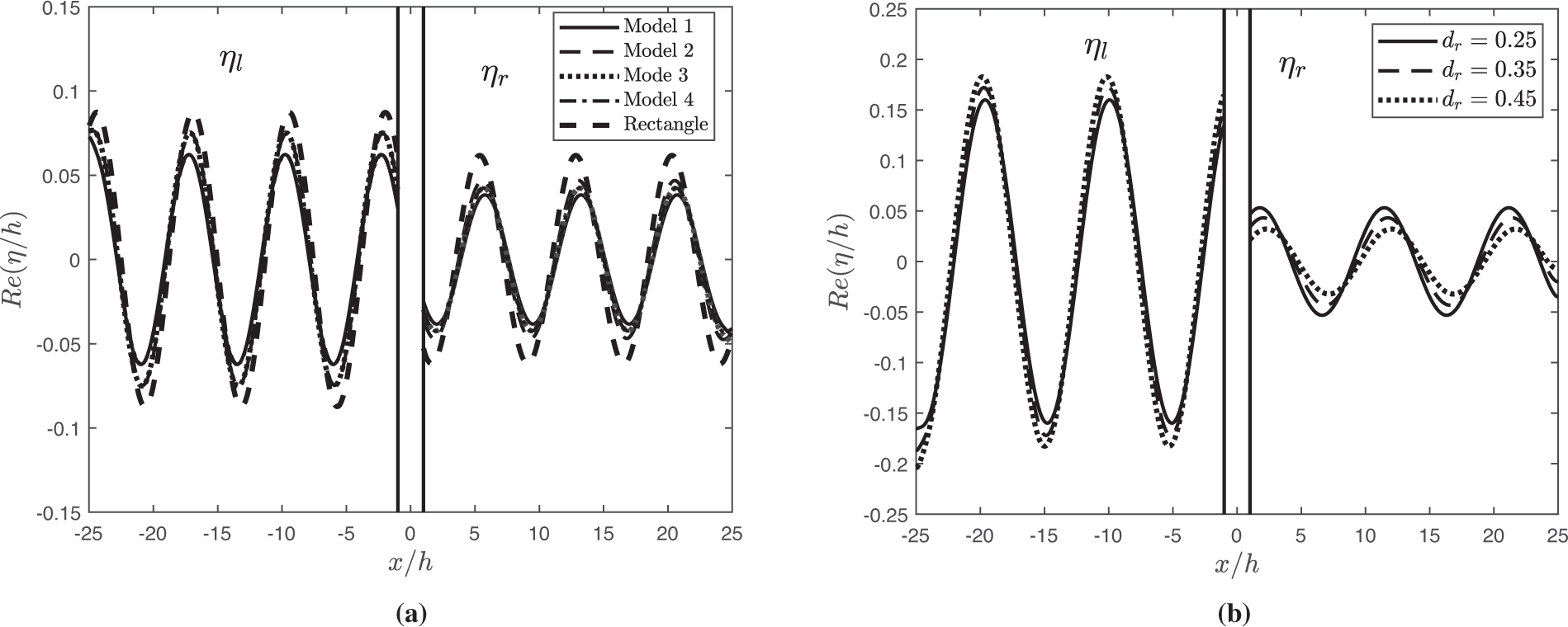
Figure 5: Variation of surface elevation
Fig. 6 demonstrates the reflection coefficient
Figure 6: Variation of
Fig. 7 demonstrates the wave reflection
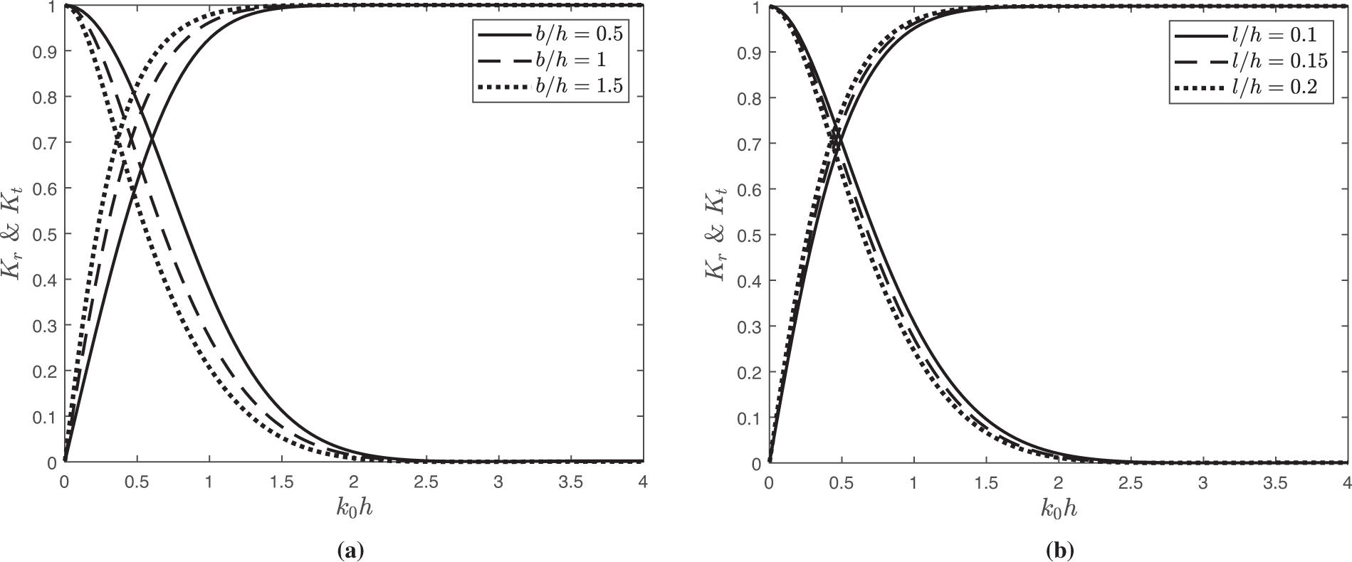
Figure 7: Variation of
Fig. 8 illustrates the horizontal and vertical forces,
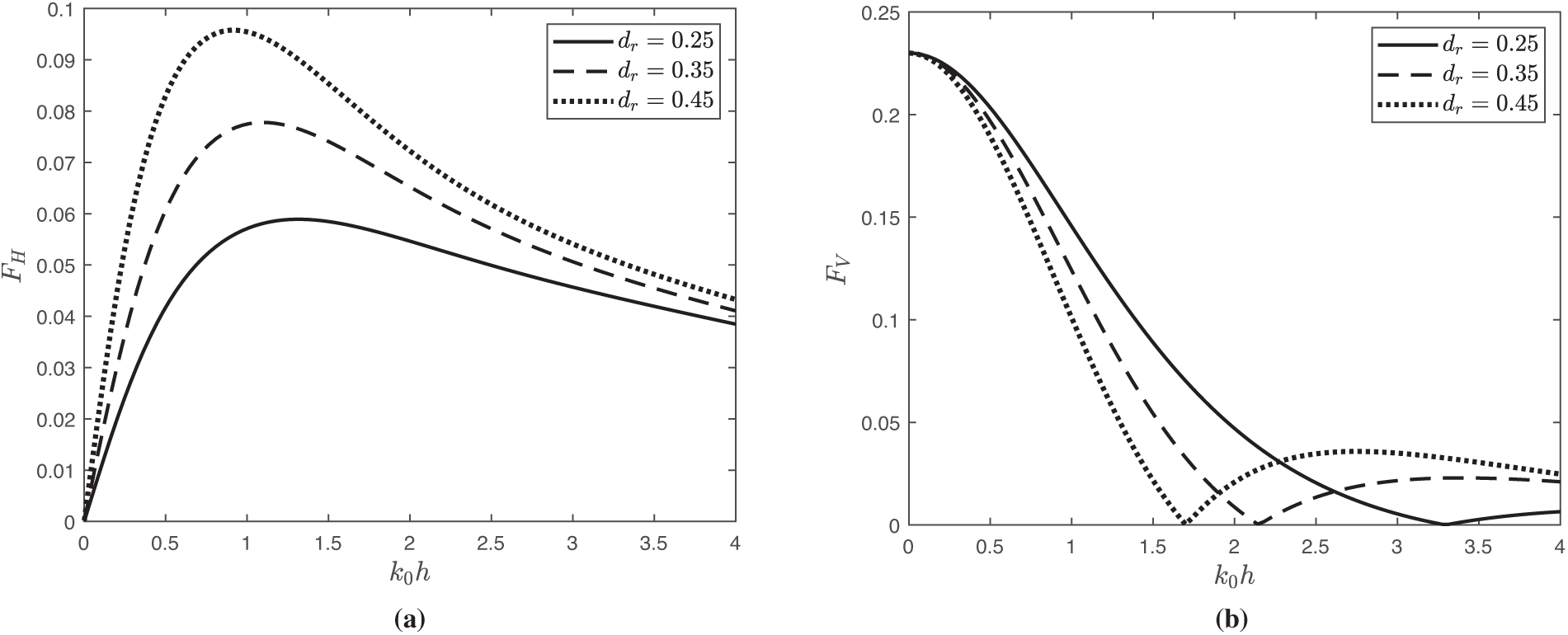
Figure 8: Variation of force (a)
Fig. 9 depicts the horizontal wave force
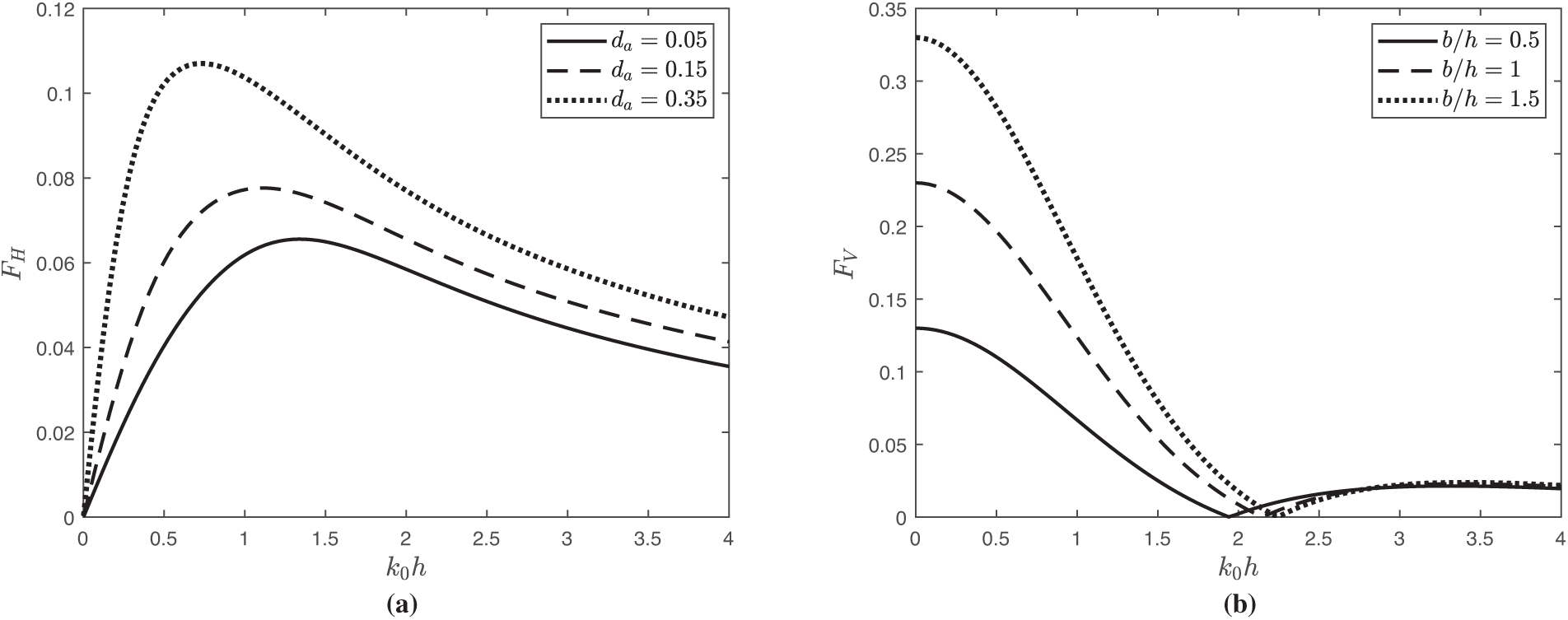
Figure 9: Variation of wave force
Fig. 10 demonstrates the horizontal force
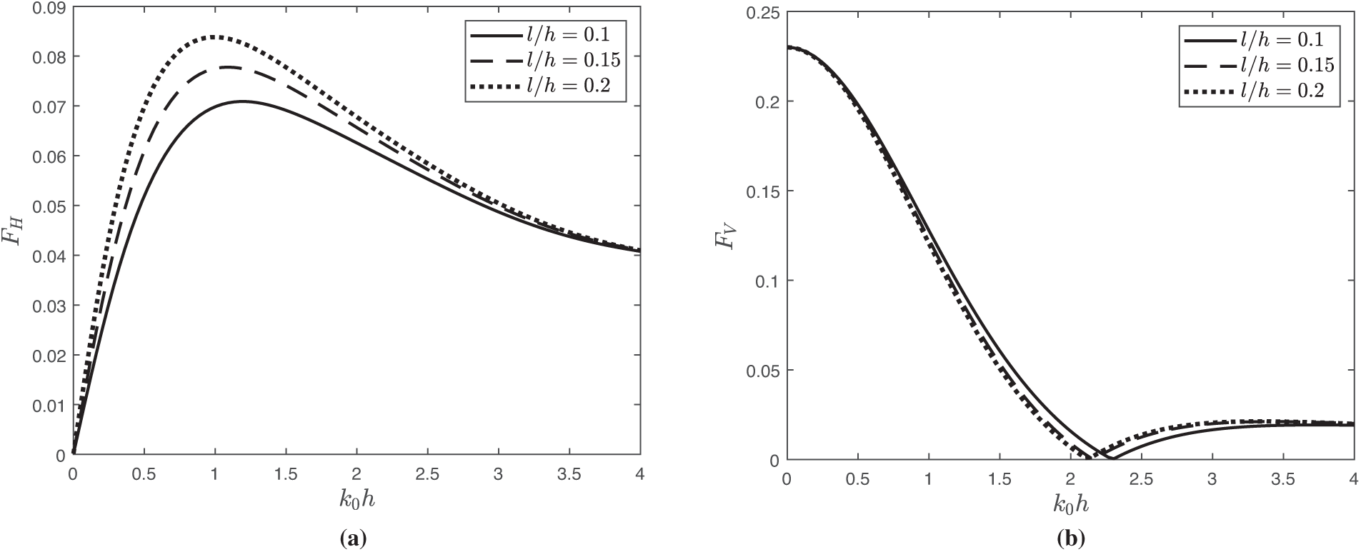
Figure 10: Variation of wave force (a)
The variation of the wave reflection
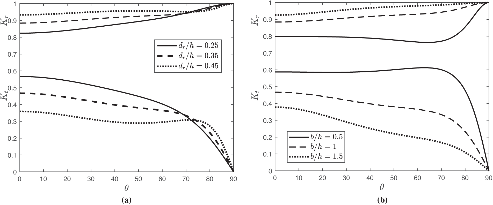
Figure 11: The
Fig. 12 shows that the reflection coefficient
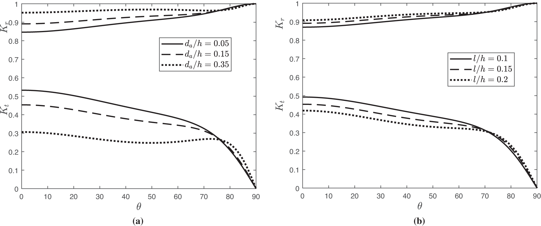
Figure 12: The
Fig. 13 illustrates the horizontal force
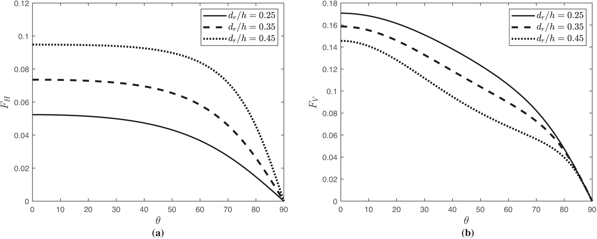
Figure 13: Variation of wave force (a)
Fig. 14 presents the wave forces on the structure
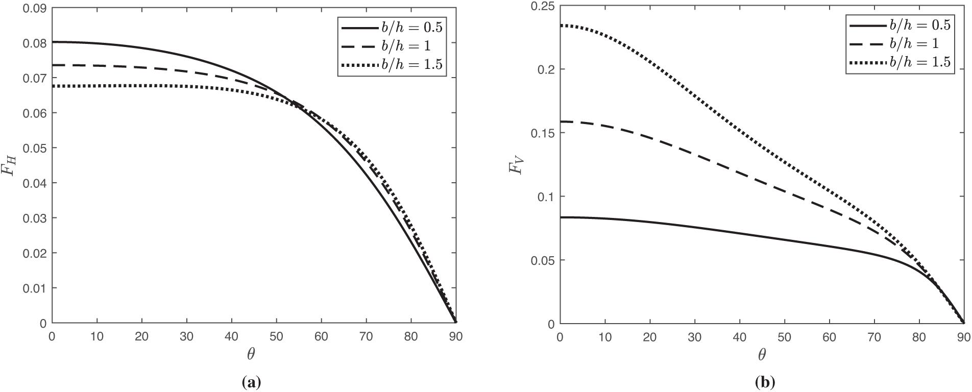
Figure 14: Variation of wave force (a)
The surface plots showing the variation of horizontal force
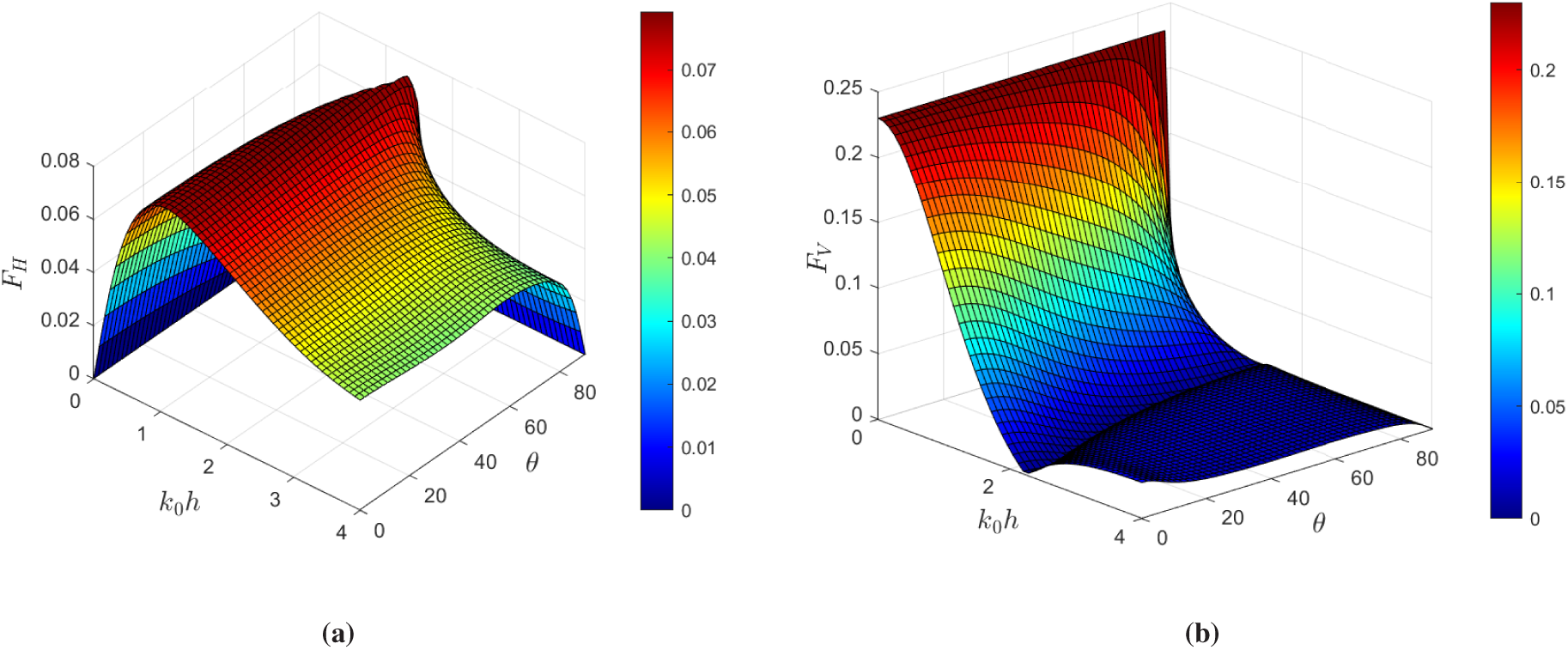
Figure 15: The surface plot of wave force (a)
This study investigates the performance of dual-curved-leg pontoon floating breakwaters in finite water depth, based on linear water wave theory. Four different curved-leg models are analyzed using the boundary element method.
• The results demonstrate that curved-leg pontoons are more effective in attenuating
• Additionally, the horizontal force acting on Model-1 increases, and the vertical force acting on Model-1 and Model-4 decreases. The study indicates that the surface elevation of Model-1 decreases both on the leeward and windward sides compared to the others.
• Finally, the results reveal that the hydrodynamic characteristics of Model-1 efficiently attenuate waves compared to other models. Moreover, the study concluded that Model-1 is considered more useful for establishing a platform and auxiliary coastel activities.
• Further analysis of Model-1 reveals that as the leg height
Overall, this study highlights the importance of optimizing structural parameters, such as leg dimensions and spacing, for the effective design and performance of a floating breakwater system. The BEM is restricted to problems for which a fundamental solution exists, which makes the treatment of nonlinear and inhomogeneous problems difficult. Future work may focus on extending the present formulation to incorporate nonlinear wave effects, inhomogeneous boundary conditions, and coupling with numerical methods such as computational fluid dynamics to overcome these limitations.
The complex pontoon breakwater investigated in this study can be further examined for all six degrees of freedom (surge, sway, heave, roll, pitch, and yaw) using high-fidelity computational fluid dynamics simulations and experimental setups, providing a more realistic representation of its dynamic behavior. Future research will address these limitations, which define the scope of the study. Additionally, future research may extend the current model by incorporating additional energy-harvesting mechanisms, such as an integrated oscillating water column system.
Acknowledgement: The authors gratefully acknowledge the valuable insights and stimulating discussions contributed by Dr. R. Gayathri of the Department of Mathematics, School of Advanced Sciences, Vellore Institute of Technology, Vellore, India, which have substantially enhanced the development of this work.
Funding Statement: This work is supported by Vellore Institute of Technology, Vellore, under a SEED grant (Sanction Order No. SG20230081).
Author Contributions: Conceptualization, Jothika Palanisamy, Chandru Muthusamy, and Higinio Ramos; methodology, Jothika Palanisamy, Chandru Muthusamy, and Higinio Ramos; validation, Jothika Palanisamy, Chandru Muthusamy, and Higinio Ramos; formal analysis, Jothika Palanisamy, Chandru Muthusamy, and Higinio Ramos; writing—original draft preparation, Jothika Palanisamy; writing—review and editing, Chandru Muthusamy and Higinio Ramos; visualization, Jothika Palanisamy and Chandru Muthusamy; supervision, Chandru Muthusamy and Higinio Ramos. All authors reviewed the results and approved the final version of the manuscript.
Availability of Data and Materials: The data supporting the findings of this study are provided within the article, as detailed in the figure captions and their corresponding discussions.
Ethics Approval: Not applicable.
Conflicts of Interest: The authors declare no conflicts of interest to report regarding the present study.
References
1. Koh HS, Lim YB. The floating platform at the Marina Bay, Singapore. Struct Eng Int. 2009;19(1):33–7. doi:10.2749/101686609787398263. [Google Scholar] [CrossRef]
2. Lamas-Pardo M, Iglesias G, Carral L. A review of Very Large Floating Structures (VLFS) for coastal and offshore uses. Ocean Eng. 2015;109:677–90. doi:10.1016/j.oceaneng.2015.09.012. [Google Scholar] [CrossRef]
3. Ohmatsu S. Numerical calculation method for the hydroelastic response of a pontoon-type very large floating structure close to a breakwater. J Marine Sci Technol. 2000;5(4):147–60. doi:10.1007/s007730070001. [Google Scholar] [CrossRef]
4. Jiang D, Wu B, Peng B, Shao Y. Dynamic response analysis of pontoon-type floating bridges subjected to wave and traffic loads. In: Proceedings of the Fourth World Conference on Floating Solutions: WCFS 2024; 2025 Dec 2–4; Hong Kong, China. Singapore: Springer Nature. p. 477–86. doi:10.1007/978-981-96-4569-5_50. [Google Scholar] [CrossRef]
5. Wang CM, Han M, Lyu J, Duan W, Jung K. Floating forest: a novel breakwater-windbreak structure against wind and wave hazards. Front Struct Civil Eng. 2021;15(5):1111–27. doi:10.1007/s11709-021-0757-1. [Google Scholar] [CrossRef]
6. Wang CM, Tay ZY. Very large floating structures: applications, research and development. Procedia Eng. 2011;14:62–72. doi:10.1016/j.proeng.2011.07.007. [Google Scholar] [CrossRef]
7. Dai J, Wang CM, Utsunomiya T, Duan W. Review of recent research and developments on floating breakwaters. Ocean Eng. 2018;158(1):132–51. doi:10.1016/j.oceaneng.2018.03.083. [Google Scholar] [CrossRef]
8. Mei CC, Black JL. Scattering of surface waves by rectangular obstacles in waters of finite depth. J Fluid Mech. 1969;38(3):499–511. doi:10.1017/s0022112069000309. [Google Scholar] [CrossRef]
9. Williams AN, Abul-Azm AG. Dual pontoon floating breakwater. Ocean Eng. 1997;24(5):465–78. doi:10.1016/S0029-8018(96)00024-8. [Google Scholar] [CrossRef]
10. Neelamani S, Rajendran R. Wave interaction with T-type breakwaters. Ocean Eng. 2002;29(2):151–75. doi:10.1016/S0029-8018(00)00060-3. [Google Scholar] [CrossRef]
11. Masoudi E. Hydrodynamic characteristics of inverse T-type floating breakwaters. Int J Maritime Technol. 2019;11:13–20. doi:10.29252/ijmt.11.13. [Google Scholar] [CrossRef]
12. Peña E, Ferreras J, Sanchez-Tembleque F. Experimental study on wave transmission coefficient, mooring lines and module connector forces with different designs of floating breakwaters. Ocean Eng. 2011;38(10):1150–60. doi:10.1016/j.oceaneng.2011.05.005. [Google Scholar] [CrossRef]
13. Masoudi E, Gan L. Diffraction waves on general two-legged rectangular floating breakwaters. Ocean Eng. 2021;235(4):109420. doi:10.1016/j.oceaneng.2021.109420. [Google Scholar] [CrossRef]
14. Ruol P, Martinelli L, Pezzutto P. Formula to predict transmission for π-type floating breakwaters. J Waterway Port Coastal Ocean Eng. 2013;139(1):1–8. doi:10.1061/(asce)ww.1943-5460.0000153. [Google Scholar] [CrossRef]
15. Sharma P, Roy R, De S. Water wave scattering by π-shaped and inverted π-shaped porous breakwaters. Cambridge, UK: Cambridge University Press; 2025. [Google Scholar]
16. Sujana Praisilin S, Gayathri R, Chandru M. Effect of trench configuration on the scattering and radiation of surface gravity waves by different floating breakwaters. Phy Fluids. 2025;37(8):087225. doi:10.1063/5.0278889. [Google Scholar] [CrossRef]
17. Rahman S, Baeda AY, Achmad A, Jamal RF. Performance of a new floating breakwater. IOP Conf Ser Mater Sci Eng. 2020;875(1):012081. doi:10.1088/1757-899x/875/1/012081. [Google Scholar] [CrossRef]
18. Lyu X, Yang Y, Mi C, Tang CM, Adeboye L, Farhan M, et al. A symmetric experimental study of the interaction between regular waves and a pontoon breakwater with novel fin attachments. Symmetry. 2024;16(12):1605. doi:10.3390/sym16121605. [Google Scholar] [CrossRef]
19. Yuan H, Zhang H, Wang G, Tu J. A numerical study on a winglet floating breakwater: enhancing wave dissipation performance. Ocean Eng. 2024;309:118532. doi:10.1016/j.oceaneng.2024.118532. [Google Scholar] [CrossRef]
20. Jain S, Bora SN. Oblique water wave scattering by a floating bridge fitted with a rectangular porous structure and the resulting waveload mitigation. Ocean Eng. 2023;275(4):114132. doi:10.1016/j.oceaneng.2023.114132. [Google Scholar] [CrossRef]
21. Hussein KB, Ibrahim M. Experimental and numerical study on the hydrodynamic performance of suspended curved breakwaters. Int J Maritime Sci Technol. 2022;69(3):123–31. doi:10.17818/nm/2022/3.2. [Google Scholar] [CrossRef]
22. El Saie Y, El Sayed A, Ehab H, Balah A. The hydrodynamic performance examination of a new floating breakwater configuration. Int J Adv Eng. 2023;9(1):1–8. doi:10.22161/ijaems.91.1. [Google Scholar] [CrossRef]
23. He Y, Han B, Han X, Xie H. Diffraction wave on the single wing floating breakwater. Appl Ocean Res. 2024;146(1):103941. doi:10.1016/j.apor.2024.103941. [Google Scholar] [CrossRef]
24. He Y, Han B, Han X, Xie H. Wave blocking performance of the symmetrical double-wing floating breakwater. Ocean Eng. 2024;303:117852. doi:10.1016/j.oceaneng.2024.117852. [Google Scholar] [CrossRef]
25. Doss A. Impact of box-type floating breakwater on motion response of hydrodynamically coupled floating platforms downstream [master’s thesis]. Delft, The Netherlands: Delft University of Technology; 2020. [Google Scholar]
26. Watanabe E, Wang CM, Utsunomiya T, Moan T. Very large floating structures: applications, analysis and design. Centre for Offshore Research and Engineering. National University of Singapore. Core report 2004-02 (2004). p. 1–30. [cited 2025 Sep 15]. Available from: https://scholar.google.com/scholar?hl=en&as_sdt=0%2C5&q=Watanabe+E%2C+Wang+CM%2C+Utsunomiya+T%2C+Moan+T.+Very+large+floating+structures%3A+applications%2C+analysis+and+design.++Centre+for+Offshore+Research+and+Engineering.+National+University+of+Singapore.+Core+report+2004-02+%282004%29.+p.++1%E2%80%9330.&btnG=. [Google Scholar]
27. Xue S, Xu Y, Xu G, Wang J, Chen Q. A novel tri-semicircle shaped submerged breakwater for mitigating wave loads on coastal bridges part I: efficacy. Ocean Eng. 2022;245:110462. doi:10.1016/j.oceaneng.2021.110462. [Google Scholar] [CrossRef]
28. Samuel SP, Gayathri R, Koley S, Muthusamy C. Motion responses with hydrodynamic factors in designing a floating breakwater and wave energy converter: a review. J Ocean Eng Mari Energy. 2025;11(1):233–63. doi:10.1007/s40722-024-00372-8. [Google Scholar] [CrossRef]
29. Lee HH, Wong SH, Lee RS. Response mitigation on the offshore floating platform system with tuned liquid column damper. Ocean Eng. 2006;33(8–9):1118–42. doi:10.1016/j.oceaneng.2005.06.008. [Google Scholar] [CrossRef]
30. Wang CM, Tay ZY. Hydroelastic analysis and response of pontoon-type very large floating structures. In: Fluid structure interaction II. Berlin/Heidelberg, Germany: Springer; 2010. p. 103–30. doi:10.1007/978-3-642-14206-2_5. [Google Scholar] [CrossRef]
31. Sun J, Jiang P, Sun Y, Song C, Wang D. An experimental investigation on the nonlinear hydroelastic response of a pontoon-type floating bridge under regular wave action. Ships Offshore Struct. 2018;13(3):233–43. doi:10.1080/17445302.2017.1356438. [Google Scholar] [CrossRef]
32. Qu K, Sun WY, Ren XY, Kraatz S, Jiang CB. Numerical investigation on the hydrodynamic characteristics of coastal bridge decks under the impact of extreme waves. J Coast Res. 2021;37(2). doi:10.2112/jcoastres-d-20-00045.1. [Google Scholar] [CrossRef]
33. Luo M, Rubinato M, Wang X, Zhao X. Experimental investigation of freak wave actions on a floating platform and effects of the air gap. Ocean Eng. 2022;253(1):111192. doi:10.1016/j.oceaneng.2022.111192. [Google Scholar] [CrossRef]
34. Khan MBM, Gayathri R, Behera H. Wave attenuation properties of rubble mound breakwater in tandem with a floating dock against oblique regular waves. Waves Rand Complex Med. 2024;34(4):2707–25. doi:10.1080/17455030.2021.1967512. [Google Scholar] [CrossRef]
35. Wu Q, Xu G, Xue S, Wang J, Li Y. Experimental and numerical investigation of combined countermeasure for mitigating tsunami forces on typical coastal T-girder bridge deck. Ocean Eng. 2023;268(6):113419. doi:10.1016/j.oceaneng.2022.113419. [Google Scholar] [CrossRef]
36. Hemanth S, Karmakar D. Hydroelastic analysis of VLFS integrated with multiple porous vertical barriers. Ships Offshore Struct. 2025;10(2):1–22. doi:10.1080/17445302.2025.2466107. [Google Scholar] [CrossRef]
37. Sharma P, Sarkar B, De S. Comparative hydrodynamic analysis of T and inverse T-shape floating breakwater in oblique wave. European J Mechan-B/Fluids. 2025;113(2):204274. doi:10.1016/j.euromechflu.2025.204274. [Google Scholar] [CrossRef]
38. Sahoo H, Gayathri R, Khan MBM, Behera H. Hybrid boundary element and eigenfunction expansion method for wave trapping by a floating porous box near a rigid wall. Ships Offshore Struct. 2023;18(8):1148–58. doi:10.1080/17445302.2022.2108227. [Google Scholar] [CrossRef]
39. Jins MM, Vijay KG, Venkateswarlu V, Behera H. Oblique wave interaction with a floating dock in the presence of inverted trapezoidal pile-rock breakwaters. Eng Anal Bound Elem. 2025;172(3):106111. doi:10.1016/j.enganabound.2024.106111. [Google Scholar] [CrossRef]
40. Wang CD, Meylan MH. The linear wave response of a floating thin plate on water of variable depth. Appl Ocean Res. 2002;24(3):163–74. doi:10.1016/S0141-1187(02)00025-1. [Google Scholar] [CrossRef]
41. Kincaid, Gary Allan. Effects of natural period upon the characteristics of a moored floating breakwater [Ph.D. dissertation]. Cambridge, MA, USA: Department of Civil Engineering, Massachusetts Institute of Technology; 1960. [cited 2025 Sep 15]. Available from: journals.cambridge.org/abstract_S0022112069000309. [Google Scholar]
42. Ji C, Bian X, Lu L, Guo J, Xu S, Lv F. 3D experimental investigation of floating breakwater with symmetrical openings and wing structures. Ocean Eng. 2024;313:119624. doi:10.1016/j.oceaneng.2024.119624. [Google Scholar] [CrossRef]
43. Ji C, Bian X, Huo F, Guo J, lian Z, Yuan Z. Experimental study on hydrodynamic characteristics of a new type floating breakwater with opening pass and wing structure. Ocean Eng. 2022;259:111923. doi:10.1016/j.oceaneng.2022.111923. [Google Scholar] [CrossRef]
Cite This Article
 Copyright © 2025 The Author(s). Published by Tech Science Press.
This work is licensed under a Creative Commons Attribution 4.0 International License , which permits unrestricted use, distribution, and reproduction in any medium, provided the original work is properly cited.
 Downloads
 Citation Tools