
 Submit a Paper
 Propose a Special lssue
 Open Access
ARTICLE
Finite Element Analysis of the Influence of End Grouting Defects in Grouted Sleeve on the Structural Performance of Precast Reinforced Concrete Columns
1 Institute of Civil Engineering and Architecture, Ural Federal University, Yekaterinburg, 620062, Russia
2 Faculty of Mechanics and Mathematics, Lomonosov Moscow State University, Moscow, 119991, Russia
* Corresponding Author: Shuoting Xiao. Email:
(This article belongs to the Special Issue: Frontiers in Computational Modeling and Simulation of Concrete)
Computer Modeling in Engineering & Sciences 2025, 145(3), 2821-2847. https://doi.org/10.32604/cmes.2025.071961
Received 16 August 2025; Accepted 20 November 2025; Issue published 23 December 2025
 View Full Text
 Download PDF
Abstract
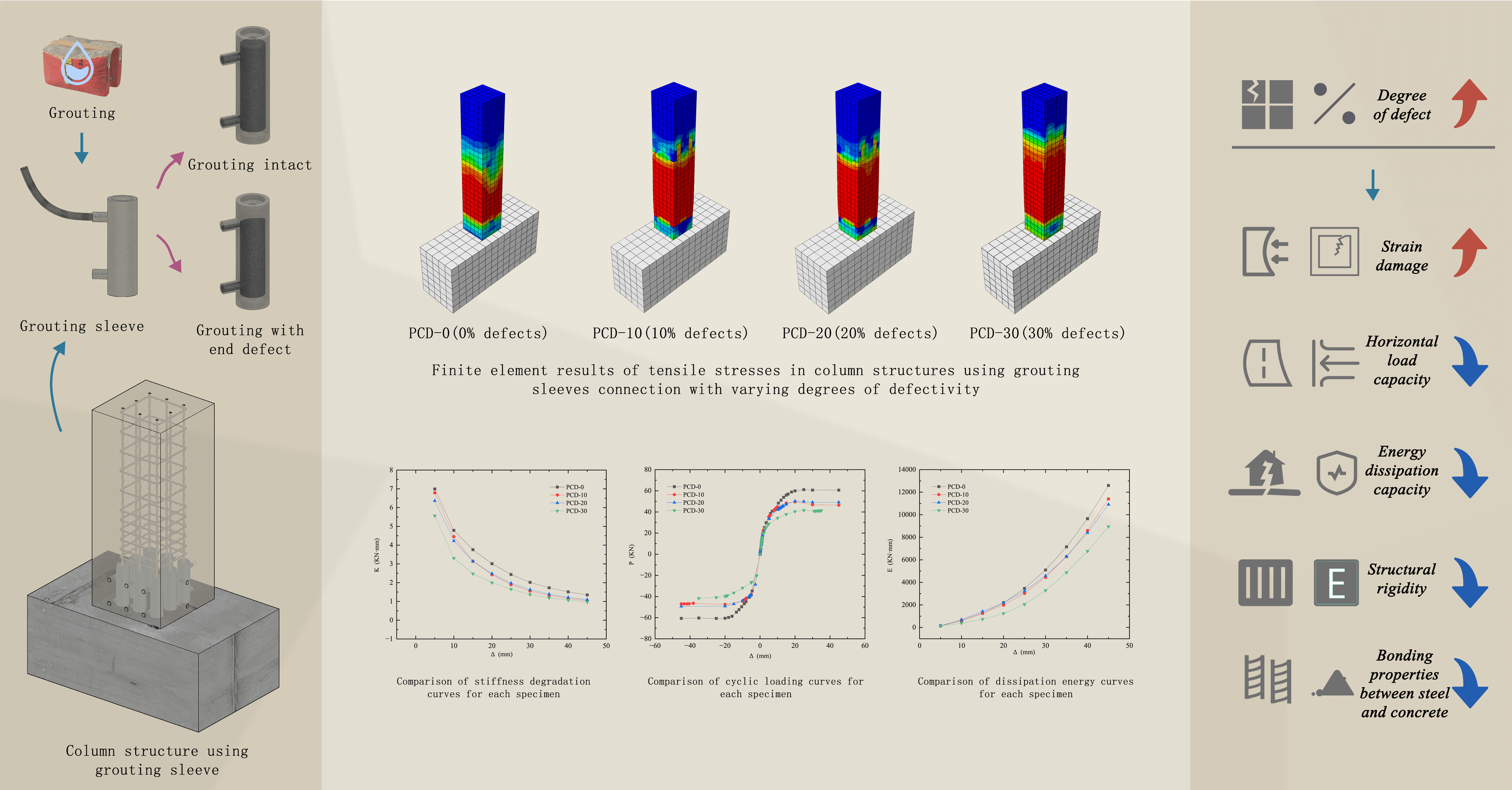
Precast concrete structures have gained popularity due to their advantages. However, the seismic performance of their connection joints remains an area of ongoing research and improvement. Grouted Sleeve Connection (GSC) offers a solution for connecting reinforcements in precast components, but their vulnerability to internal defects, such as construction errors and material variability, can significantly impact performance. This article presents a finite element analysis (FEA) to evaluate the impact of internal grouting defects in GSC on the structural performance of precast reinforced concrete columns. Four finite element models representing GSC with varying degrees of defects were used to investigate the effects on mechanical properties, including bearing capacity, stress-deformation behavior, and stiffness degradation. The study highlights the significant impact of internal grouting defects on the mechanical performance of GSC, with findings indicating a decrease in stiffness, increased plastic deformation, and reduced energy dissipation as the proportion of internal defects rises. The analysis reveals that the internal defects in GSC act as stress concentration points, leading to early crack formation and accelerated damage under cyclic loading. By improving construction quality and reducing the prevalence of grouting defects, the adverse effects on the performance of GSC can be mitigated. Compared to defect-free specimens, those with defects of 30% exhibited a 31.23% reduction in horizontal bearing capacity, highlighting the importance of minimizing defects in practical engineering applications.Graphic Abstract
Keywords
As one of the key development directions in the current construction industry, precast concrete (PC) structures are increasingly being applied in contemporary building projects [1,2] due to advantages such as shortened construction periods [3], reduced on-site labor demand [4], and decreased construction waste emissions [5]. Nonetheless, historical lessons indicate that PC structures may exhibit inadequate seismic performance due to structural connections [6]. In traditional PC systems, the beam–column or slab connections, which rely solely on dowels or shear friction, exhibit inherently weak shear and ductility capacities, leading to more pronounced damage at the connection joints and seams during earthquakes [7–9]. Therefore, as the application of PC construction becomes more widespread globally, developing high-performance connection joint designs has become particularly essential.
Various connection technologies have been developed for PC structures, each with distinct characteristics and applicable scenarios. For example, typical dry connections bolted connections, which use high-strength bolts penetrating through precast components or clamping precast components through connectors to achieve semi-rigid joints, typically possess good seismic energy dissipation capacity superior to that of concrete, with high assembly efficiency and high post-disaster repairability [10–13]. However, some studies have found that concrete local crushing failure tends to occur near bolt holes [14,15], and an improved method is to increase the size of washers or pads [16,17]. Another engineering solution is to use steel shoe connections to replace bolted connections. Research has demonstrated that such connections can achieve ultimate drift angles and cumulative energy dissipation higher than those of cast-in-place connection structures, while the stiffness can reach the level of cast-in-place connection structures [18–20].
Reinforcement grouted sleeve connection (GSC), which enables direct load transfer by connecting rebars and is able to fully develop the ultimate stress in the spliced reinforcing bars [21], has emerged in recent years as one of the effective connection methods for PC structures. By injecting high-performance grout into the sleeve, the embedded rebars within the precast components are effectively joined. Generally, a longer anchorage length, a larger diameter for both the spliced rebars and the sleeve, and a higher-strength grout material lead to greater load-bearing capacity of the GSC [22,23]. Meanwhile, while the required strength can be fully developed, larger sleeves and rebars also result in greater cumulative slip [21]. Experimental studies on the dynamic behavior have shown that GSC exhibits superior load-bearing capacity and maximum strain under dynamic loading compared to static loading, highlighting its effectiveness in seismic applications [24]. Yang et al. [25] proposed an effective stress–strain relationship model for GSC, enabling more accurate performance evaluation of PC columns utilizing GSC. Based on the above studies, it can be found that, except for individual short anchorage conditions, the tensile strength of grouted sleeve connections generally satisfies the requirements specified in standards ACI 318 [26] and AC-133 [27] for the tensile performance of reinforcement connectors, which stipulate a strength greater than 1.25 times the specified yield strength of the reinforcing bars. Their findings further suggest that GSC can be modeled as an equivalent rebar with higher elastic modulus and yield strength, whose equivalent elastic modulus degrades as the initial construction tolerance increases.
Industrialized production carried out under rigorous standards enables stringent quality control of sleeves, ensuring that sleeves installed on-site meets the structural requirements for mechanical performance and environmental service conditions [28]. The factors that affect the performance of GSC structures arise primarily during construction and the post-construction stage. For instance, Liu et al. [29] experimentally demonstrated that elevated temperatures significantly deteriorate the bond strength between high-strength grout and reinforcing bar in GSC, and embedding stirrups as a reinforcement measure can prevent concrete splitting failure and enhance the bond performance. Further, factors such as improper construction techniques during installation, poor grouting quality, and variability in material properties can introduce defects that become critical latent vulnerabilities, affecting its performance [30,31]. As shown in Fig. 1, the main failure modes of GSC include outside reinforcement rebar fracture, concrete splitting failure, and bond slip between the rebar and the grout [29]. Previous experimental studies have shown that insufficient grout strength and inadequate anchorage length can cause bond-slip failure in GSC, whereas product defects can lead to sleeve rupture [32]. Moreover, grouting defects can result in failure modes such as rebar fracture, rebar yielding pull-out, or rebar pull-out without yielding [33]. As the scale of precast component construction expands, grouting defects are among the most common issues encountered during actual construction. Increasing numbers of on-site inspection reports indicate that local grouting defects occur inside sleeves due to impeded grout flow, leakage, or process variations [30,31].
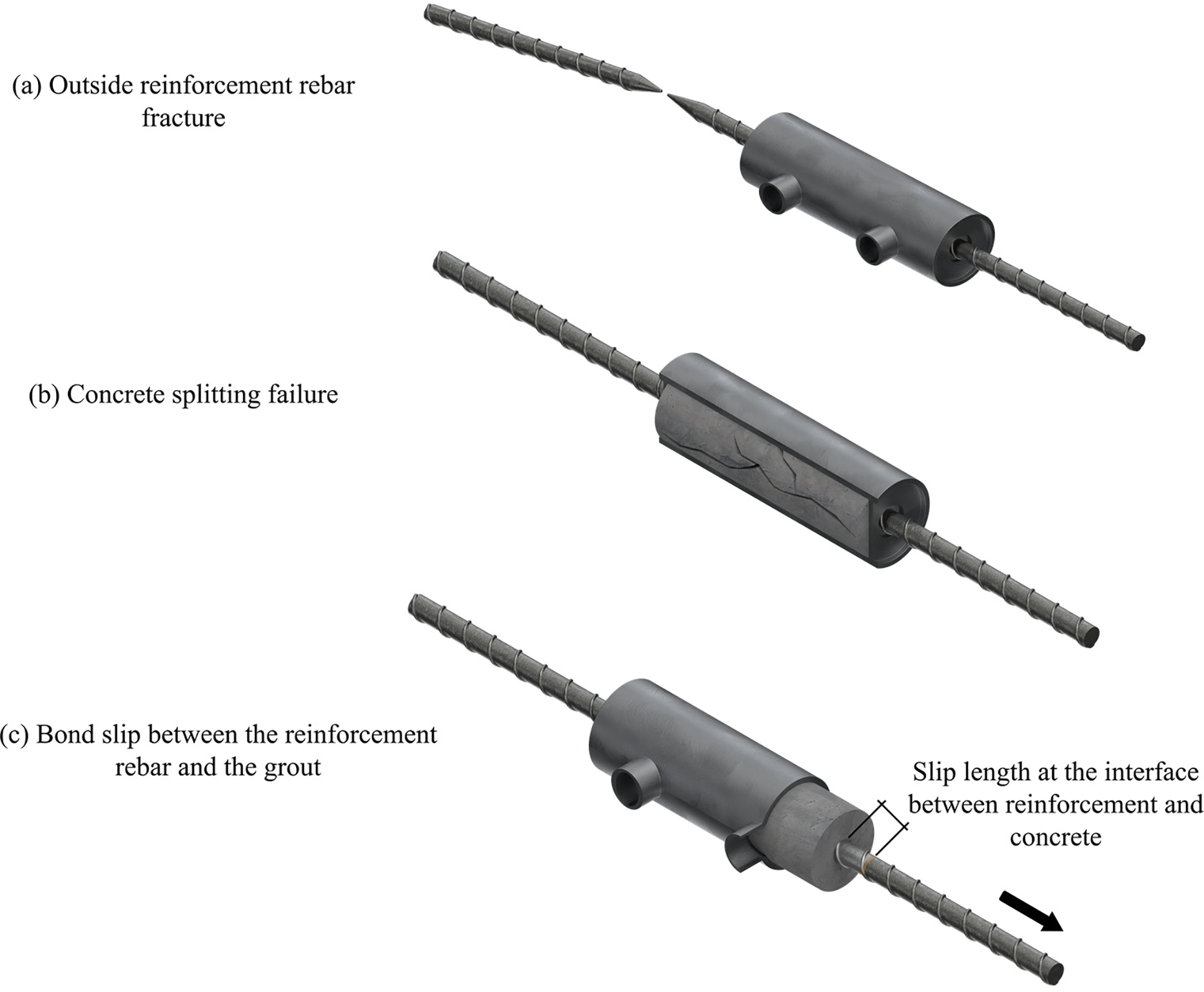
Figure 1: Three typical failure modes of GSC
Zheng et al.’s [34] experimental study on defects due to insufficient vertical grouting demonstrated that for defective sleeve connections exhibiting rebar fracture failure, the yield load and ultimate load are similar to those of fully GSC, but the failure displacement is significantly greater. Guo et al. [35] performed uniaxial tensile tests on 42 connectors considering various grouting defects. Their results demonstrate that the type and spatial distribution of defects exhibit significant segmented effects on the bearing capacity and ductility of fully grouted sleeve connections. Taking commercial fully grouted sleeves with 14 mm rebars as an example, when the end defect length reaches approximately 3 times the rebar diameter (i.e., 42 mm), the connection performance deteriorates significantly, and the failure mode transitions from rebar fracture to rebar anchorage failure. Furthermore, under equivalent effective anchorage lengths, uniformly distributed defects result in the lowest ultimate bearing capacity, followed by central defects, with end defects having the least impact, indicating that the more discontinuous the component space, the more interrupted the load transfer becomes. Conversely, for sleeve joints with grouting density defects, when the defect value increases from 10% to 30%, the bond strength does not change significantly. Similarly, Guo et al.’s [36] experimental results on the effect of grouting defects on the mechanical properties of rebars in fully GSC indicate that for sleeves with insufficient grout fullness, when the grout fullness is above 80%, the strength and deformation performance of the rebar decrease gradually; however, when this value drops below 80%, the tensile strength and maximum elongation of the connection decrease significantly. Zhang et al. [31] developed a method combining Acoustic Emission and Ultrasonic Testing to quantitatively evaluate internal defects in GSC in prefabricated buildings and monitor in real-time the damage process of grouted sleeves with varying degrees of internal defects under tensile loading. Their study defined a defect rate of 30% as the maximum allowable defect for GSC. Overall, the failure type of GSC is mainly influenced by both the effective anchorage length and defect morphology. Floating voids during vertical grouting are inevitable [35], and it can be said that grouting void defects at the top of GSC are one of the common defects in actual engineering construction. Most of the aforementioned studies focus on the performance of defective GSC under monotonic tensile loading. Combined with the previous studies by Guo et al. [36] and Zhang et al. [31], it is confirmed that there exists a threshold for the volume ratio of void defects within GSC, beyond which the failure mode will change and performance will deteriorate significantly. Defects lead to reduced strength and deformation capacity, and can change the failure mechanism from rebar fracture to bond-slip. Therefore, based on and compared to previous research, the objective of this work is to conduct a stepped parametric analysis on the performance of GSC structures with top-end void defects at different defect rates under cyclic loading, in order to understand the impact of such defects on the seismic performance of GSC structures.
Numerical methods such as finite element analysis (FEA) can provide detailed visualization of stress fields throughout the entire structure, revealing stress concentrations, load transfer paths, and regions of high stress gradients. In the work of Sun et al. [37], 3D FEA models were established using Abaqus for six PC columns reinforced with steel-fiber reinforced polymer composite bars (SFCB), analyzing failure modes, load-displacement responses, strain distribution in SFCB, and cross-sectional curvature along the columns. The model’s load prediction had an average error of 2.8%, with ultimate deformation prediction errors all within 20%. Liu and Xiao [38] used Abaqus to numerically simulate the seismic performance of PC columns with GSC after fire exposure, with the maximum difference from experimental values being only 5.0%. In the work of Ding et al. [39], which proposed a type of PC column with grouted sleeve connections embedded in engineered cementitious composite (ECC) shells, a three-dimensional nonlinear FEA model was established using Abaqus. After experimental validation, they analyzed the effects of parameters such as ECC height and thickness, axial compression ratio, strengths of ordinary concrete and ECC, yield strength and reinforcement ratio of longitudinal bars, and number of sleeves on the seismic performance of columns. Their results found that when the ECC height is approximately 2 times the section height and the shell thickness is 1/5 to 1/3 h, it can significantly improve bearing capacity, ductility, and energy dissipation under economic conditions, while excessive axial compression ratio, number of sleeves, and ordinary concrete strength would weaken ductility.
To more intuitively understand the impact of GSC end grouting defects on the mechanical properties and stress-deformation behavior of precast reinforced concrete columns, this work established FEA models of PC columns with different sleeve end grouting defect ratios. Based on previous research findings and engineering practice, four representative end defect levels were selected: 0% (defect-free control group), 10%, 20%, and 30% (approaching the maximum allowable defect rate proposed by Zhang et al. [31]). Through FEA, this study: (1) analyzed the stress distribution patterns and stress concentration phenomena within columns under different top-end defect ratios; (2) compared the ultimate bearing capacity, yield load, and failure modes of columns under various defect degrees; (3) investigated the effects of top-end defects on lateral deformation, load-displacement curves of columns, analyzing the stiffness degradation patterns resulting from insufficient grouting at the top regions of sleeves; and (4) explored the mechanisms by which top-end defect length and severity affect overall structural performance, revealing the bond deterioration mechanisms between rebars and grout material specifically in the upper defective regions, and the research results provide quantitative basis for the degradation of mechanical properties under various sleeve top-end defect ratio conditions.
2 Methodology, Materials and Modeling
The research methodology follows a structured FEA analytical framework as depicted in Fig. 2. The process initiates with the development and validation of the baseline FEA model against experimental data, ensuring accurate representation of the mechanical behavior of intact grouted sleeve connections. Subsequently, parametric variations are introduced to simulate different defect scenarios, with grouting void ratios ranging from 0% to 30%. The validated models undergo cyclic loading analysis, generating data on structural response including load-displacement relationships, damage evolution patterns, and energy dissipation characteristics.
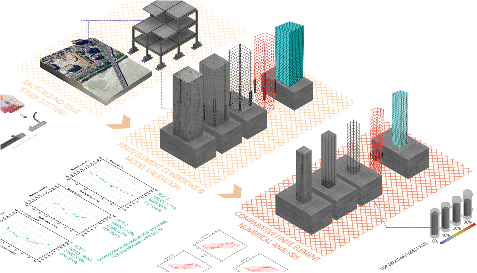
Figure 2: Research route and framework
The FEA models developed in this study represent precast reinforced concrete columns connected to concrete footings through grouted sleeve connections, utilizing the software Abaqus. The modeling approach employs a three-dimensional framework to capture the interaction between concrete, steel reinforcement, grout material, and sleeve components under combined axial and lateral cyclic loading.
The structural system consists of three primary components including a PC column with embedded longitudinal and transverse reinforcement, a reinforced concrete footing serving as the foundation element, and grouted sleeve connections positioned at the column-footing interface to provide structural continuity. The concrete elements are modeled using eight-node linear brick elements with reduced integration (C3D8R), which effectively capture the behavior of reinforcing bars and other steel components embedded in concrete [40], while reducing overall shear locking issues and hourglass phenomena [41,42]. The mesh density distribution of the model follows design principles with refined discretization near the critical connection regions and coarser mesh in regions of lower stress gradients.
Steel reinforcement bars are represented using two-node linear truss elements (T3D2) that are embedded within the concrete host elements through the embedded element method [43]. This imposes a perfect-bond (no-slip) kinematic constraint to transfer forces between reinforcement and concrete; bond–slip behavior and bond degradation are not explicitly represented in the present model [44]. The sleeves are modeled as thick-walled cylinders using shell elements (S4R) with thickness definitions to capture both membrane and bending behavior.
2.1 Constitutive Settings of Concrete Materials
The materials constitutive models incorporate nonlinear behavior for all components. Concrete is characterized by using the concrete damage plasticity (CDP) model, which simulates the effect of damage on elastic stiffness and its recovery during crack opening and closing processes through independent damage variables, considering the different behaviors under tensile and compressive conditions [45]. In Abaqus, using the CDP model to simulate the described structure is superior to the Brittle Cracking (BC) model, as it can reproduce pull-out or fracture and load-displacement behavior. From an overall accuracy evaluation perspective, CDP is superior to BC, and the BC model tends to exhibit premature cracking and a shorter hardening segment [33]. This work refers to the methods and parameters recommended in the Chinese standard GB 50010-2010 [46] to determine the constitutive model of concrete. The parameters and models input in Abaqus below are consistent with the typical recommended values for normal-strength concrete and have been used in similar numerical studies on GSC [47,48].
In Abaqus, the input CDP parameters include a dilation angle ψ of 30°, eccentricity ϵ of 0.1,
Tensile cracking and compressive crushing are the two types of material damage assumed in the CDP model. The evolution of the yield or failure surface is mainly governed by the tensile equivalent plastic strain
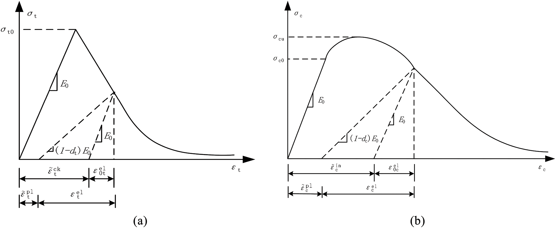
Figure 3: Uniaxial stress-strain relationship of concrete (a) Schematic of uniaxial tensile stress-strain relationship and cracking strain
In Fig. 3, when the stress does not reach the failure stress
Thus, the expressions for the uniaxial tensile damage factor
where,
2.2 Constitutive Settings of Steel
Previous studies and code requirements have demonstrated that the performance of GSC is equivalent to or greater than that of reinforcing bars, and that the connection should not fail or undergo significant slip before the rebar itself fails [28,52,53]. In addition, experimental research has shown that, prior to the precast component reaching its ultimate load-carrying capacity, the GSC material always remains in the elastic range [54]. Based on these observations, in this study, the GSC material and the reinforcing steel are both simplified as linear elastic materials in the FEA, and an ideal elastic–plastic model is adopted for simulation. Neglecting the bond-slip at the rebar-grout interface is a recognized limitation, but it is acceptable for simulating the overall hysteretic behavior under low-cycle fatigue [44,53]. The GSC is always assumed to remain elastic, and the bond-slip at the interface is neglected. In the FEA, a unified elastic modulus of
2.3 FEA Model Validation Framework
The validation of the FEA model follows mainstream validation strategies established by previous research, evaluating the model’s ability to capture the overall mechanical behavior of the structure by comparing load–displacement curves, and verifying the local response by comparing strain distributions, crack patterns, and failure modes at key locations using contour plots. In order to verify that the numerical strategy adopted in this paper can accurately reproduce both the global and local behavior of grouted sleeve connections, defect-free PC columns with grouted rebar sleeves designed by Zhao et al. [55] were used as a baseline for model validation. As shown in Fig. 4, the cross-sectional dimensions of the PC column in the validation model are 600 mm × 600 mm, with a total height of 2000 mm. The lower part contains a 15 mm cast-in-place concrete joint, and the column is connected to a 1400 mm × 800 mm × 650 mm concrete footing via grouted sleeve connections.
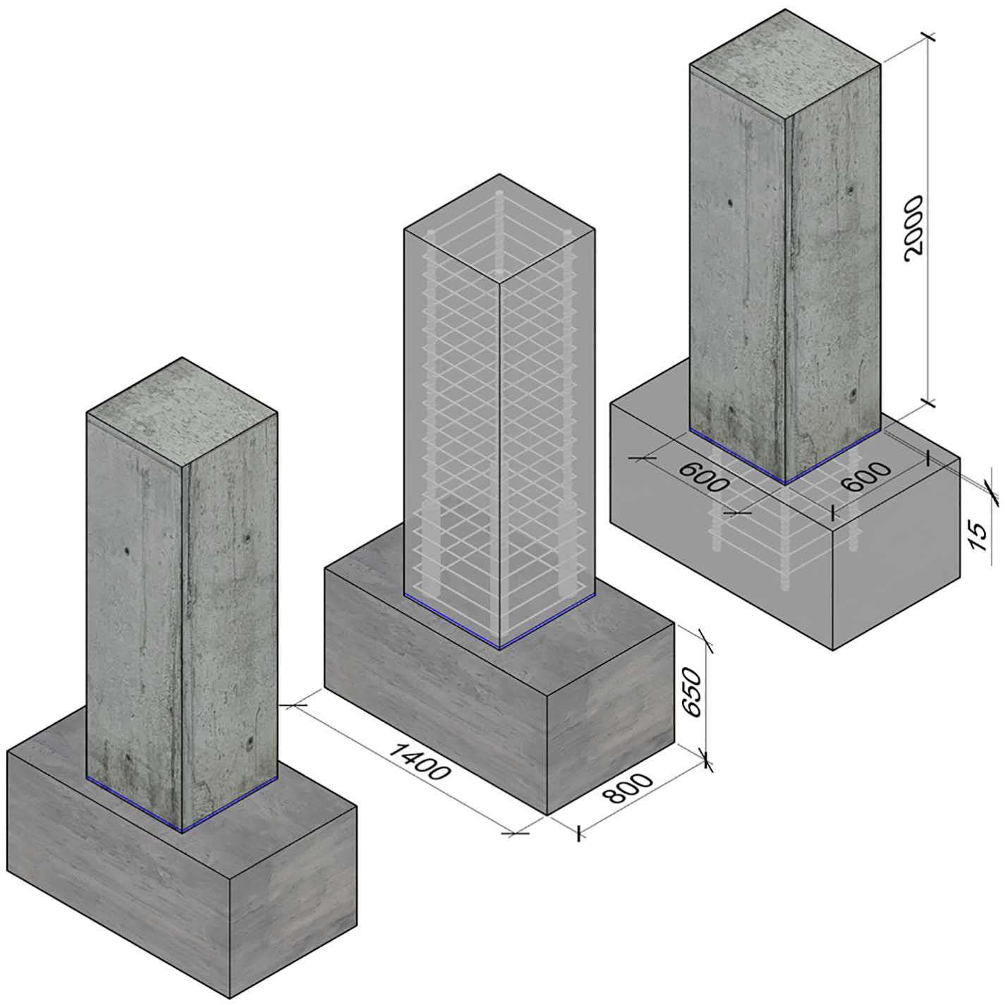
Figure 4: Specimen dimensions for verification model
Three specimens from the study by Zhao et al. [55], designated as PC36-1, PC36-3, and PC25-1, were selected for FEA model validation. The three specimens differ in the diameter of the reinforcing bars, the size of the sleeves used, and the configuration of the stirrups. The specimens PC36-1 and PC36-3 use longitudinal reinforcement with a diameter of 36 mm, while the specimen PC25-1 uses longitudinal reinforcement with a diameter of 25 mm. The differences in the sizes of the sleeves and longitudinal reinforcement used in the specimens are shown in Fig. 5. The sleeve connected to the 36 mm diameter longitudinal reinforcement has an outer diameter of 83 mm, a length of 483 mm, and an anchorage length of 230 mm for the rebar inside the sleeve. The sleeve connected to the 25 mm diameter longitudinal reinforcement has an outer diameter of 64 mm, a length of 320 mm, and an anchorage length of 150 mm for the rebar inside the sleeve.
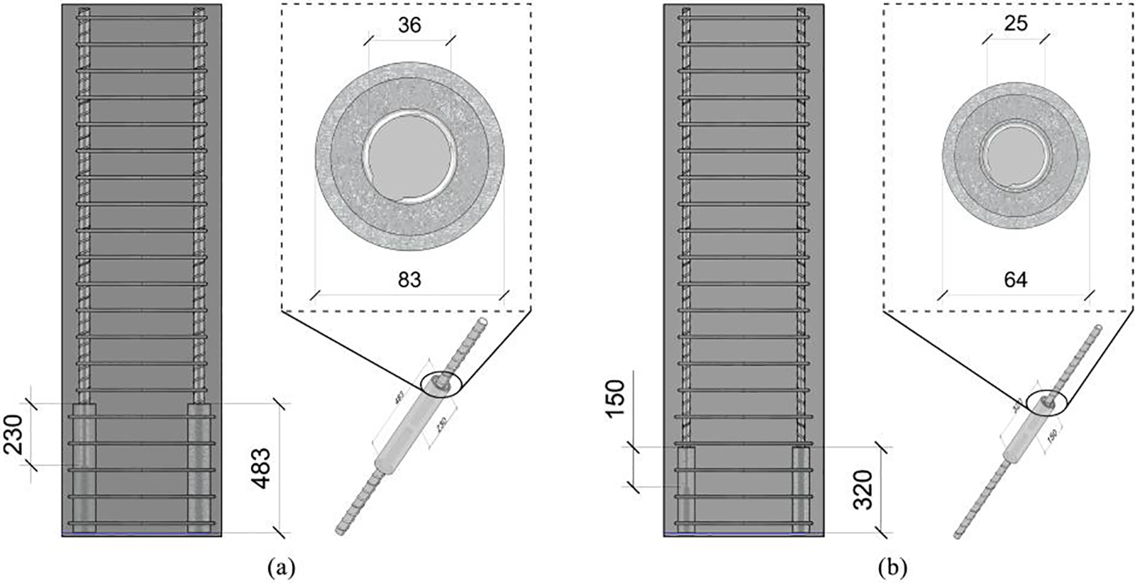
Figure 5: Dimensions of longitudinal reinforcement and sleeves used in specimens for validation model (a) Specimen using 36 mm diameter reinforcing bars and 83 mm outer diameter sleeves; (b) Specimen using 64 mm diameter reinforcing bars and 25 mm outer diameter sleeves
As shown in Fig. 6, the FEA model was established in Abaqus. The bottom surface of the foundation footing is fully constrained in all degrees of freedom (
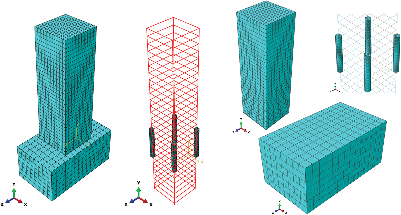
Figure 6: The FEA model established for verification specimens in Abaqus
The validation of the finite element model was also conducted on specimens with sleeves containing top grouting defects. This work selected GSC columns with 10% top grouting defects from the work of Li et al. [56] as the benchmark to further verify the capability of the modeling strategy in this study to reproduce global and local responses under defect conditions through comparative validation. To ensure methodological consistency, except for the loading amplitude and the newly added defect modeling strategy, the overall settings including material constitutive models, element types, and meshing remained consistent with Sections 2.1–2.3. The displacement step size was incrementally increased based on 8.8 mm. The defect modeling strategy was the same as that used in the finite element comparative models with defects in the following sections.
2.4 Comparative Framework for FEA Models with Defects
Based on the validated baseline model, additional FEA models were established to investigate the effects of grouting defects in GSC on the mechanical behavior of PC columns. This included one PC column with a GSC without internal grouting defects (PCD-0), and three PC columns with GSCs containing different levels of grouting defects (PCD-10, PCD-20, and PCD-30). The concrete column dimensions, concrete footing dimensions, sleeve dimensions, rebar diameters, and reinforcement arrangements in all four specimen models are identical, as shown in Fig. 7.
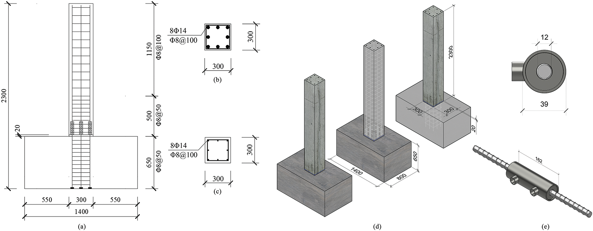
Figure 7: Design of FEA models for defect effects (a) longitudinal reinforcement arrangement of specimens; (b) reinforcement arrangement in the sleeve area sleeve area; (c) reinforcement arrangement in the upper area of the column; (d) overall dimensions of specimens; (e) sleeve dimensions
In the test specimen configuration, the PC columns have cross-sectional dimensions of 300 mm × 300 mm and a height of 1650 mm. Both the precast columns and the footing are made of Chinese standard GB/T 50010–2010 [46] Grade C30 concrete with a compressive strength of 34.5 MPa. The elastic modulus of concrete input in Abaqus is set to
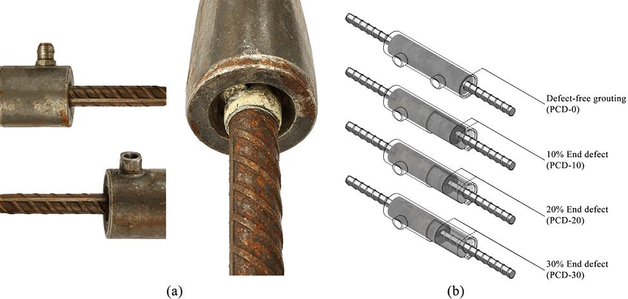
Figure 8: Schematic diagram of end defects in sleeve grouting (a) sleeve with end grouting defect; (b) schematic design of the degree of defect at the end of the FEA model
As shown in Fig. 9, in Abaqus, the global mesh size for the concrete foundation is 100 mm, the mesh size for the concrete column members is 60 mm, the mesh size at the concrete joint between the column and pile cap is 20 × 60 mm2, and the global mesh size for the steel reinforcement and sleeves is 18 mm. The modeling strategy for comparative study follows the same configuration as the validation models. The footing base is fully constrained in all degrees of freedom (
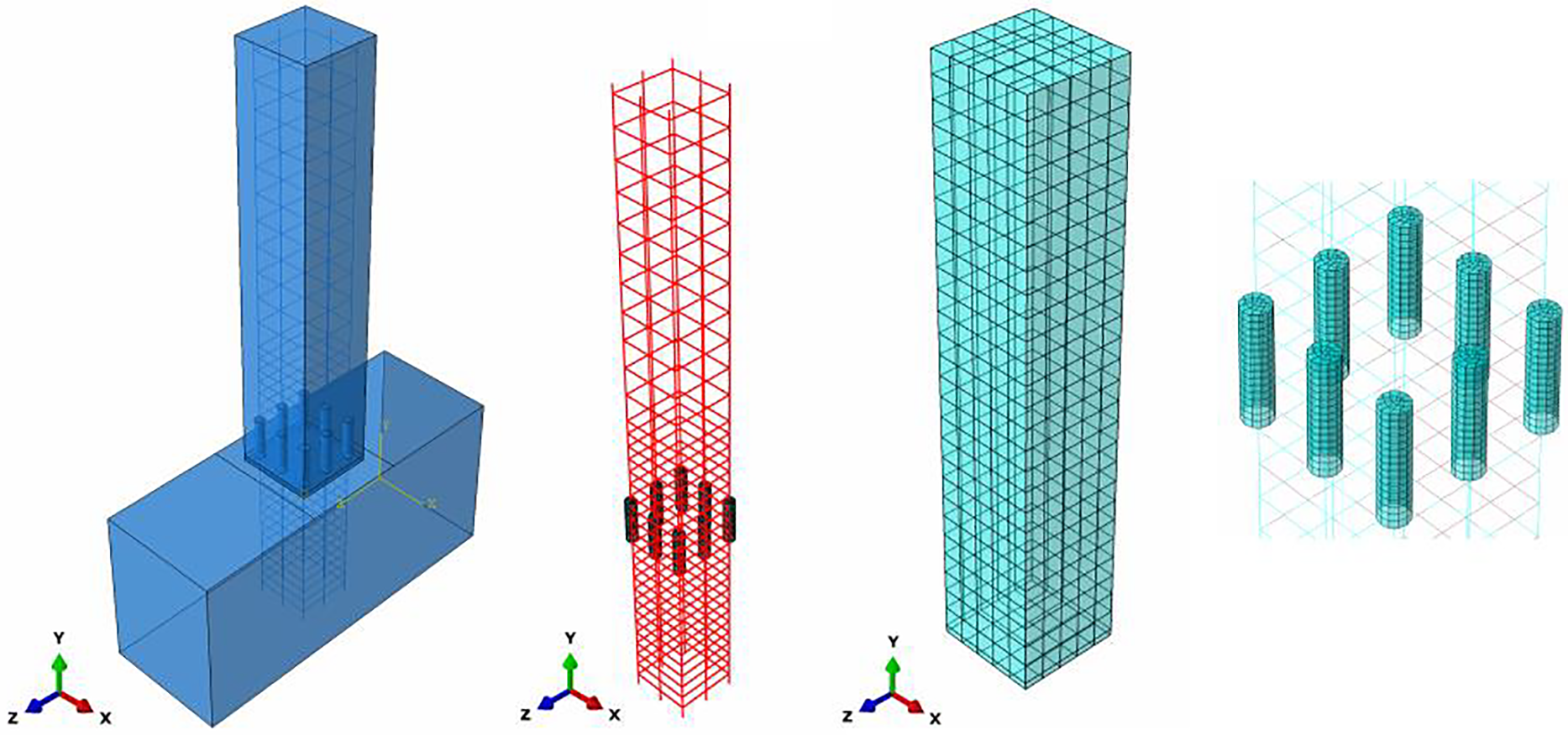
Figure 9: The FEA model established for comparative analysis specimens in Abaqus
3 Comparison and Validation of Models
As shown in Fig. 10, three representative precast columns with different cross-sectional dimensions and reinforcement layouts reported by Zhao et al. [55] were modelled. The final crack patterns observed in the tests [55] are juxtaposed with the concrete damage contours obtained from the finite-element analysis in Fig. 10, the coincidence in crack locations, failure modes and damage extents supplies an intuitive basis for the subsequent quantitative comparison.
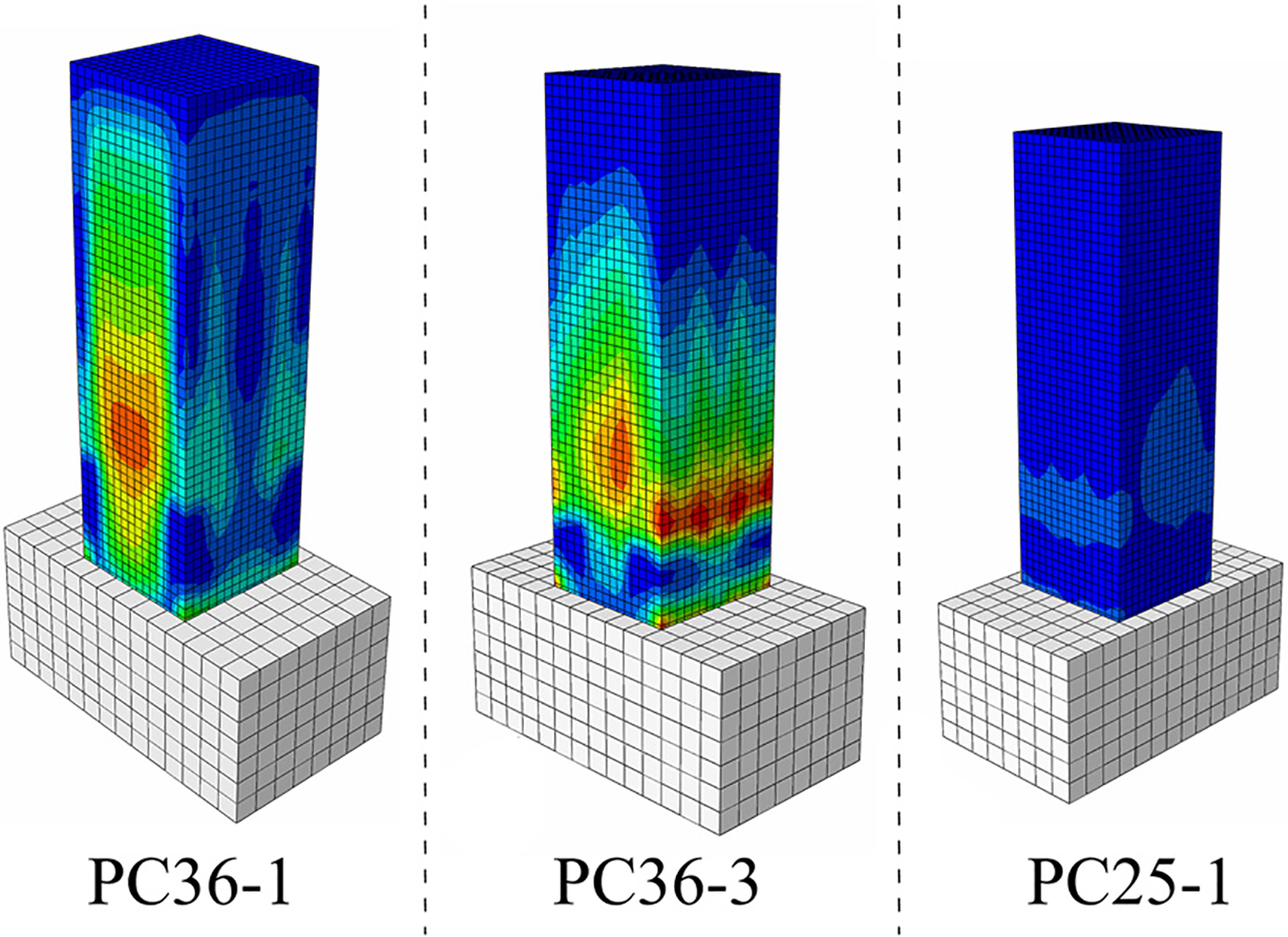
Figure 10: Comparison of results of finite element models developed according to work [55]
Fig. 11 quantifies the full-process predictive capability of the proposed numerical strategy under cyclic loading, collating the lateral load–displacement hysteresis curves of the precast columns in the experimental study [55] with the finite-element results, and simultaneously depicting the evolution of the relative error. During the initial-stiffness stage the finite-element curves are slightly higher than the measured ones, probably because early slip at the sleeve interface was not considered in the model. For progressive damage growth, the finite-element error shows a “small-then-large” trend consistent with previous reports [58,59], attributable to the nonlinear amplification of cumulative damage caused by repeated yielding of the reinforcement and the connection.
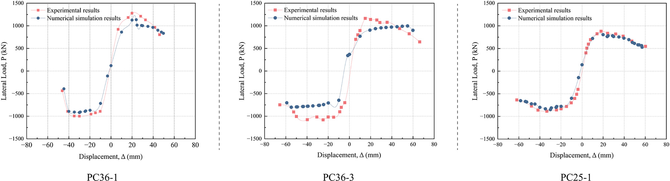
Figure 11: Comparison of experimental and numerical lateral load–displacement hysteresis curves (with percent error) for specimens without defects
As illustrated in Fig. 11, the FEA lateral load–displacement hysteresis curves obtained for specimens PC36-1, PC36-3 and PC25-1 in Zhao et al. [55] yield normalized root-mean-square errors (NRMSE) of 11.70%, 18.85% and 12.56%, mean absolute percentage errors (MAPE) of 13.36%, 19.49% and 9.90%, and coefficients of variation (COV) of 10.85%, 15.60% and 16.69%, respectively. The corresponding overall values are 14.37% for NRMSE, 14.25% for MAPE and 14.38% for COV—all below the commonly accepted 20% threshold. Consequently, the discrepancy between the experimental and numerical hysteresis curves is small, confirming that the Abaqus FEA model is highly reliable.
The lateral load-displacement hysteretic curves obtained from the finite element analysis of specimens with 10% defects under low-cycle repeated loading were compared with the force-displacement skeleton curves of 10% top grouting defects reported by Li et al. [56], yielding the results shown in Fig. 12. Overall, the finite element results can reproduce the complete hysteretic response under defect conditions, with similar trends in the reduction of initial stiffness, the peak of the skeleton curve and subsequent strength degradation in the softening segment, as well as the gradually increasing loop area shrinkage as the cycles progress. Similar to the defect-free reference model, compared to experimental results, the finite element numerical analysis results show smaller force values and faster decay of post-peak unloading stiffness. From the perspective of error evolution, the relative error in the pre-yielding stage is small, with amplified errors near the peak value and in the post-peak large displacement stage, and the error magnitudes in positive and negative loading directions show slight asymmetry. The cause of this deviation can be understood from the idealization perspective of modeling. The model adopts perfect embedment constraints for the reinforcement-grout interface, with energy dissipation mainly derived from damage and softening of concrete and grout materials and yielding of reinforcement. Therefore, the pinching effect and unloading stiffness degradation induced by reinforcement-grout interface slip/degradation in the experiments are underestimated to a certain extent, manifesting as relatively fuller numerical hysteretic loops and slightly underestimated residual displacement. On the other hand, the ideal elastic-plastic behavior of reinforcement without considering the Bauschinger effect will slightly underestimate the cyclic softening after repeated yielding, resulting in slightly slower decay of strength and stiffness in several cycles after the peak. As the defect ratio increases, the contribution of the aforementioned interface effects in the specimen increases, hence the error shows a growth trend from small to large with displacement amplitude and number of cycles.
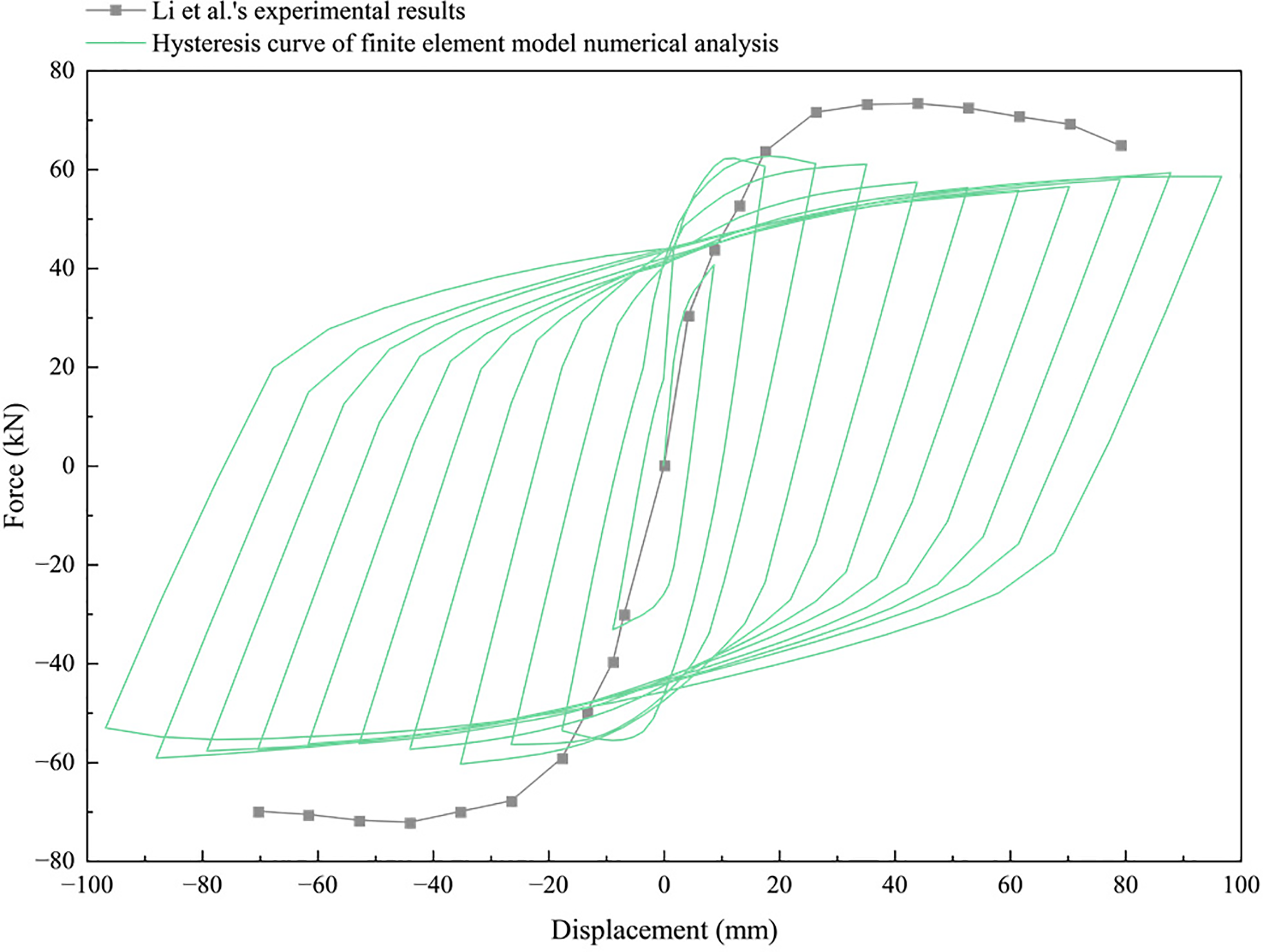
Figure 12: Comparison of experimental and numerical lateral load–displacement hysteresis curves (with percent error) for specimens with defects
Statistical quantification of the errors between the numerical and experimental hysteretic curves in Fig. 12 yields NRMSE = 18.28%, MAPE = 16.66%, and COV = 19.06%. All errors metrics are below the previously mentioned 20% threshold, indicating that the model accuracy for specimens with defects is within the engineering acceptable range. Compared to the finite element model of defect-free specimens, the numerical simulation errors of the finite element model for specimens with defects have increased, but the increment is commensurate with the conservative deviation resulting from not explicitly considering interface slip and reinforcement cyclic hardening.
4.1 Analysis of Mechanical Damage and Strain Results
Fig. 13 presents the DAMAGEC (Damage in Compression) contour plots obtained from FEA calculations in Abaqus for each specimen model. The results indicate that specimens PCD-10, PCD-20, and PCD-30 exhibit more fully developed compressive damage in the concrete near the grout sleeve joints, with increased defect areas and expanded regions of damage development. The compressive damage is primarily concentrated in the concrete areas adjacent to the grout sleeve joints. This is because tensile damage occurs earlier in this part of the concrete during tension, and under reverse loading, compressive damage develops, causing the DAMAGEC in this region to evolve earlier and more significantly. Since specimen PCD-0 has no grouting defects in the GSC region, the progression of damage in the adjacent concrete during compression is relatively slow.
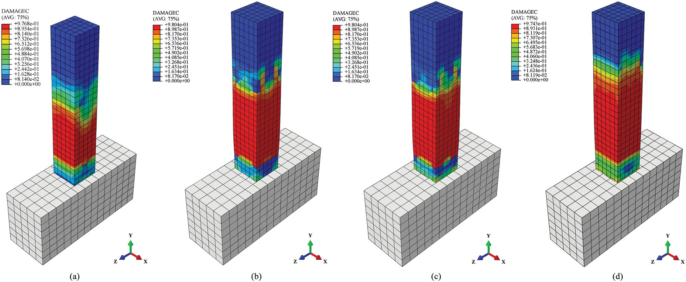
Figure 13: Damage in compression (DAMAGC) comparison of FEA modelling results (a) PCD-0; (b) PCD-10; (c) PCD-20; (d) PCD-30
In the verification results and comparative analysis of differences and defects (see Figs. 10 and 13), it can be observed that the damage of PC columns utilizing GSC is mainly concentrated at the top and bottom of the GSC. This phenomenon is similar to the experimental and FEA results reported by Zhang et al. [60] for full-scale columns with GSC, whose experimental results indicated that the failure of stirrups led to insufficient confinement of the longitudinal reinforcement, aggravating the buckling of the longitudinal bars. As a result, the lateral bearing capacity decreased rapidly, and cracks were ultimately observed to concentrate around the top of the GSC, indicating significant local damage had occurred.
The DAMAGET (Damage in Tension) contour plots obtained from FEA calculations are shown in Fig. 14. Specimen PCD-0 exhibits very limited tensile damage development, whereas specimens PCD-10, PCD-20, and PCD-30 display earlier onset and greater degrees and extents of tensile damage near the grout sleeve joint region.
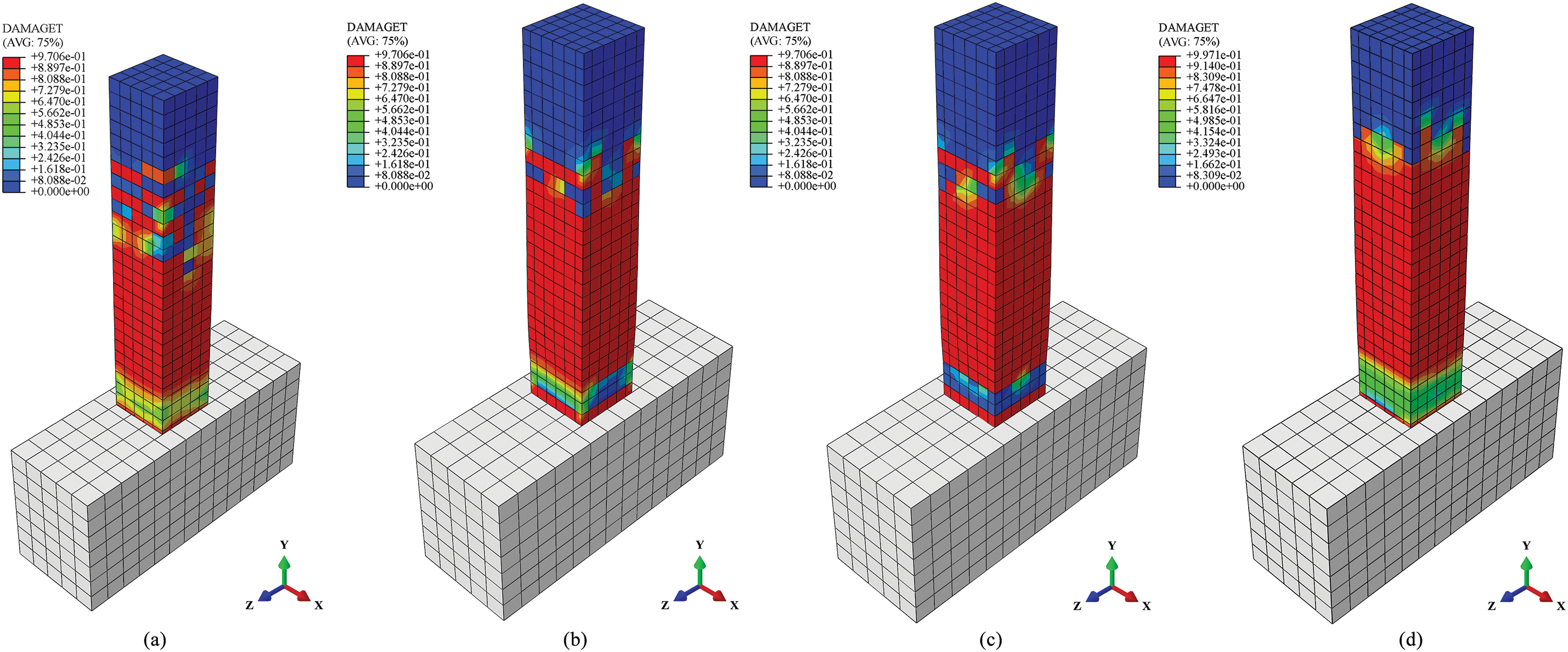
Figure 14: Damage in tension (DAMAGT) comparison of FEA modelling results (a) PCD-0; (b) PCD-10; (c) PCD-20; (d) PCD-30
Fig. 15 shows the PEEQ (Equivalent Plastic Strain) contour plots from the FEA simulation results. In the vicinity of the grout sleeve joint region of specimen PCD-30, the steel elements exhibit more fully developed plastic deformation, while in the same region of specimen PCD-0, the cumulative plastic deformation of the steel elements is relatively small. This is due to the greater number of defects present in the grout sleeve joints of PCD-30, causing the steel components in these joints to bear loads earlier, reach significantly higher stress levels, and undergo plastic deformation sooner. Consequently, the steel components of PCD-30 have higher cumulative plastic strain values.
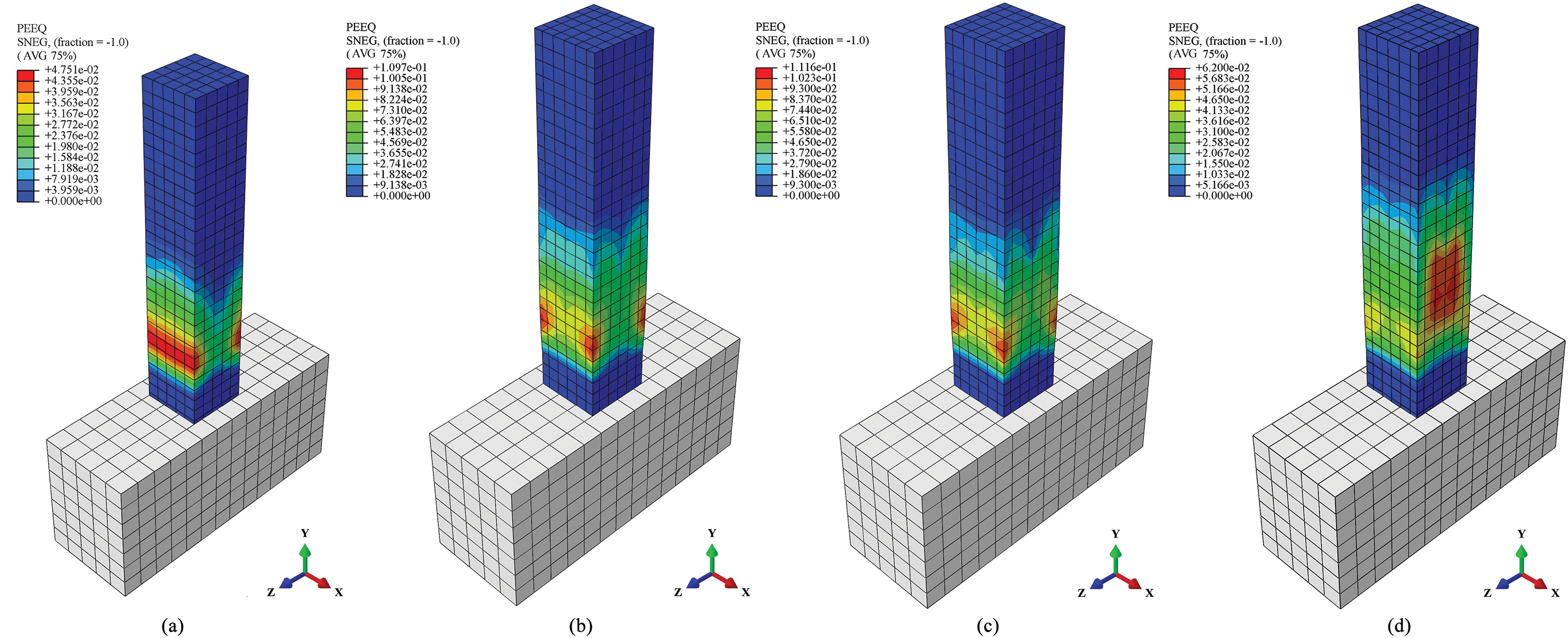
Figure 15: Equivalent plastic strain (PEEQ) comparison of FEA modelling results (a) PCD-0; (b) PCD-10; (c) PCD-20; (d) PCD-30
4.2 Load-Displacement Curve Comparative Analysis
Fig. 16 shows the comparison of the load-displacement curves for specimens PCD-0, PCD-10, PCD-20, and PCD-30. By examining their different cyclic characteristics, it can be observed that PCD-0 exhibits the best elastic hysteresis performance with excellent seismic energy dissipation capacity. Evidently, the presence of defects has a negative impact on the mechanical properties of the connections. For PCD-10, PCD-20, and PCD-30, as the internal defects in the grout sleeves increase, the area of hysteresis loops decreases, and the energy dissipation capacity of the specimens gradually reduces. Under repeated loading, the bond strength between the rebar and concrete diminishes, and the existence of internal defects accelerates this degradation. The internal defects increase the bond stress between the rebar and concrete, leading to faster crack formation and more rapid damage in the grout sleeve region.
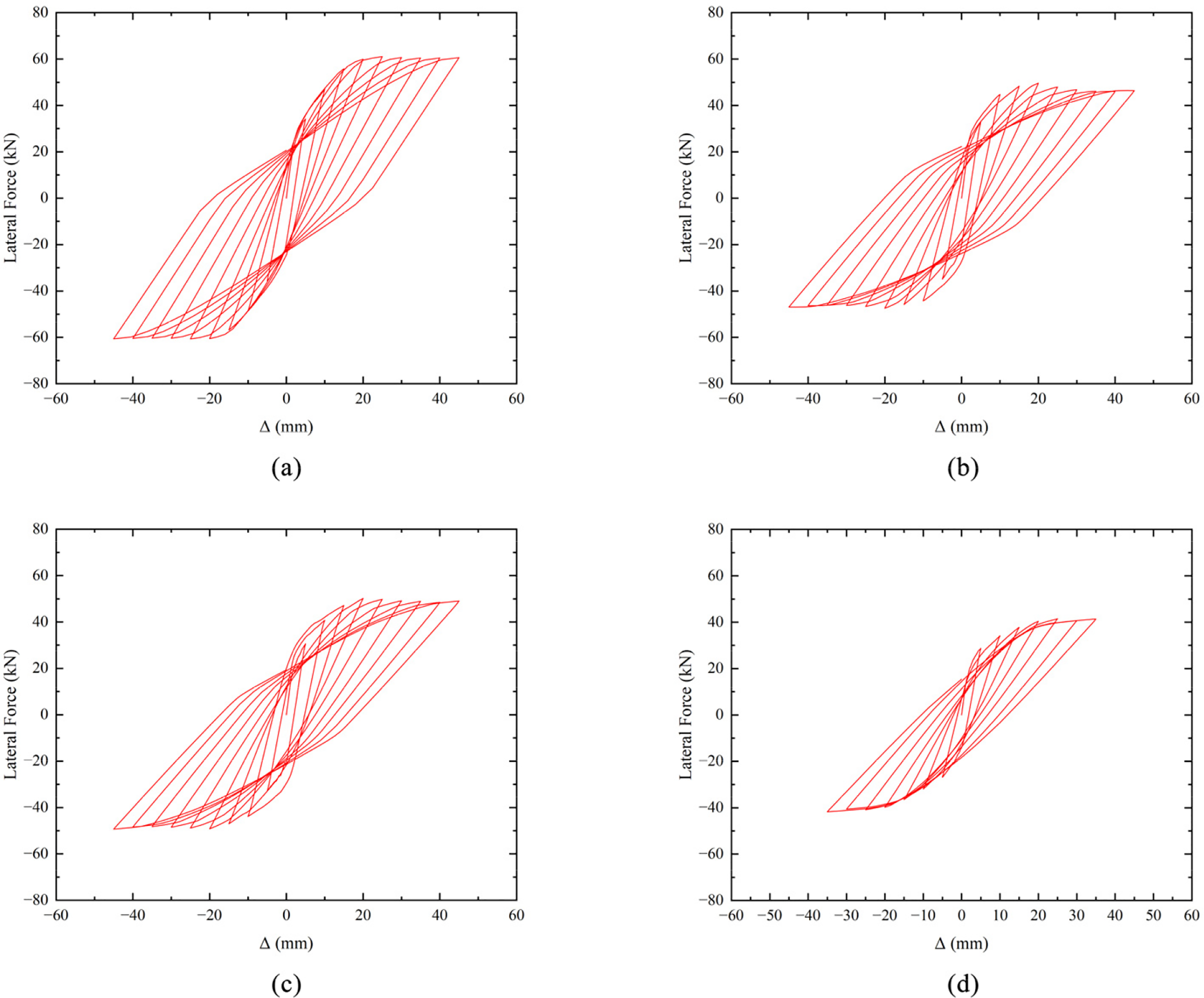
Figure 16: Comparison of load-displacement curves of specimens (a) PCD-0; (b) PCD-10; (c) PCD-20; (d) PCD-30
By comparing the maximum envelope curves of the load-displacement responses of the four specimens, as shown in Fig. 17, the curve of PCD-0 has the steepest slope and the highest horizontal bearing capacity. With the increase in the proportion of internal defects, the horizontal bearing capacity of specimens with defective joints decreases. Considering forward loading, the peak load of PCD-0 is 61.05 kN, while the peak load of PCD-30 is only 67.99% of that of PCD-0. In the case of reverse loading, the peak load of PCD-0 is 77.07 kN, whereas the peak load of PCD-30 is 68.77% of that of PCD-0. These results indicate that the presence of 30% internal defects in the GSC leads to a significant reduction in the horizontal bearing capacity of the specimens. Further comparative analysis reveals that specimens with the most internal defects have lower yield and bearing capacities and deteriorate more severely under reverse loading. The primary reason is that the increase in internal defects weakens the horizontal bearing capacity of the specimens; even under smaller loads and displacements, these defects can cause slippage between the rebar and concrete.
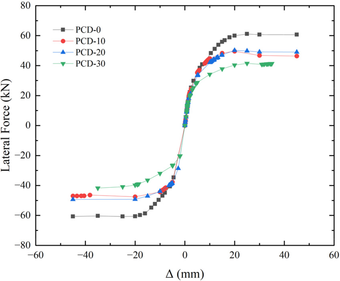
Figure 17: Comparison of displacement-load envelope curves of the specimens
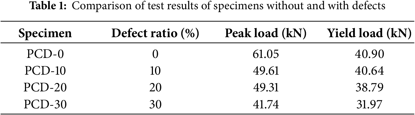
Table 1 presents a comparison of the mechanical properties of the specimens, and the results similarly indicate a significant correlation between the grouting defect rate of GSC and the structural performance parameters. The analysis of peak load demonstrates that as the defect rate increases from 0% to 30%, the horizontal load-bearing capacity of the specimens shows a decreasing trend. Specifically, compared to the defect-free specimen PCD-0 (peak load 61.05 kN), the peak load capacities of the specimens with 10%, 20%, and 30% defect rates decrease by 18.75%, 19.23%, and 31.63%, respectively. The similar mechanical performance parameters exhibited by PCD-10 and PCD-20 suggest the existence of a plateau period in performance degradation within this defect rate range. The variation in yield load with increasing GSC defect rate indicates that low defect rates have a limited effect on the mechanical behavior in the elastic stage, whereas when the defect rate exceeds the 20% threshold, the yield load declines more rapidly. The degradation of the ductility coefficient is most pronounced, with the values for PCD-10, PCD-20, and PCD-30 decreasing by 26.32%, 31.25%, and 44.08%, respectively, compared to PCD-0. Grouting defects weaken the plastic deformation capacity and energy dissipation capacity of the structure, which has a substantially negative impact on seismic performance.
4.3 Comparative Analysis of Energy Dissipation Capacity
Under cyclic loading, the specimen absorbs energy during the loading phase and releases energy during the unloading phase. The energy dissipation can typically be represented by the “ring-shaped” area enclosed by a complete loading cycle on the load–displacement curve, as illustrated in Fig. 18. This energy is expended due to plastic flow and damage evolution, and analyzing it facilitates fatigue and fracture assessment of the specimen. By extracting the reaction force
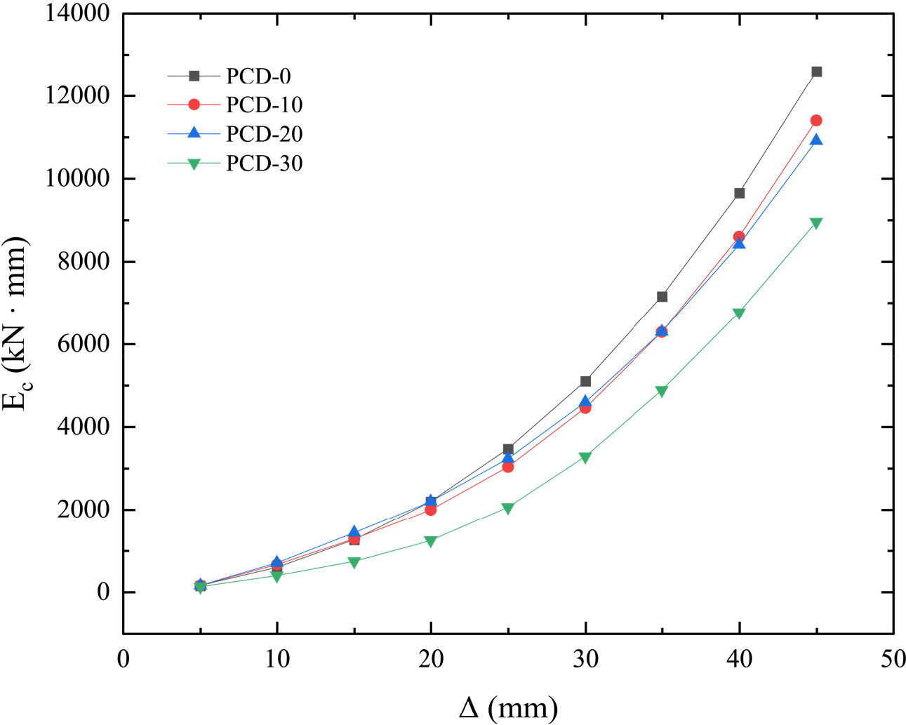
Figure 18: Comparison of the relationship curves between cumulative dissipated energy
The comparison of the relationship curves between cumulative dissipated energy
4.4 Comparative Analysis of Specimen Stiffness Degradation
The change in specimen stiffness can be represented by the variation of the secant stiffness coefficient
In Eq. (6),
Based on the FEA calculation results, the stiffness-displacement curves for each specimen can be obtained (Fig. 19). From the figure, it is evident that the shear stiffness of the specimens is inversely proportional to the displacement change; during the displacement loading stage, the stiffness decreases as the displacement load increases. All specimens exhibit similar stiffness degradation trends. In the initial stage of displacement loading, the slopes between points on the curve are relatively large. As the displacement increases, the slope gradually decreases, and the damage development in the components of each specimen intensifies progressively. In the later stages of displacement loading, most of the damage cracks have fully opened and expanded. New damage cracks are generated and propagate in a similar manner, while the existing damage slows down the occurrence and propagation of new damage. Eventually, the curves of all specimens tend to converge in the final loading displacement region, which can be attributed to the similarity in damage development mechanisms.
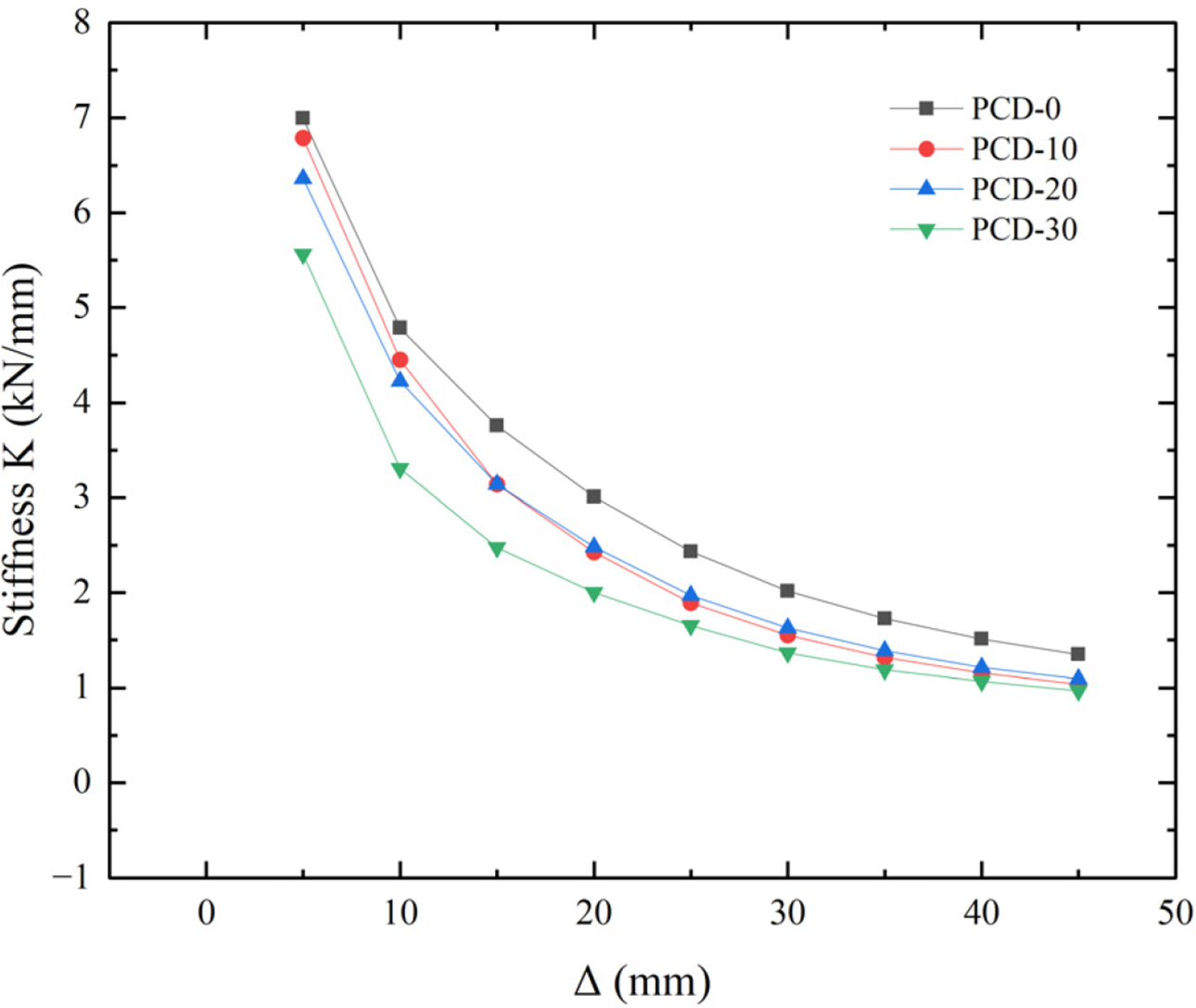
Figure 19: Comparison of stiffness degradation curves of the specimens
Compared with the other specimens, PCD-10 has an initial stiffness value similar to that of PCD-0 but slightly smaller. Starting from a displacement value Δ of 15 mm, specimens PCD-10 and PCD-20 exhibit similar stiffness degradation patterns. At the maximum displacement value, PCD-10, PCD-20, and PCD-30 have similar final stiffness values, all of which are less than that of PCD-0. Due to having the highest proportion of defects, PCD-30 exhibits the lowest initial stiffness (79.57% of PCD-0), and as the displacement Δ increases, its stiffness values remain lower than those of the other specimens.
The numerical finite-element framework developed in this study was first benchmarked against the three defect-free precast columns reported by Zhao et al. [55]. The comparison shows that the replication error of the hysteretic curves for the intact specimens is markedly lower than 20%. A slightly larger error is observed for the specimen with the largest cross-section and the highest reinforcement ratio. This is most probably because, in the late cycles, the internal stress redistribution and repeated yielding are more severe, while the CDP model in the FE solver still marginally underestimates the softening rate associated with such cumulative damage, thereby amplifying the prediction error around the peak segment. Nevertheless, the deviation remains within a highly credible range and does not compromise the overall validity of the model. On this basis, the model was next applied to columns incorporating purposely introduced voids, representing a 10%, 20% and 30% loss of grout at the top of the anchorage zone inside the sleeve. When analyzing defective components, neglecting interface slip and bond degradation [44,57] may lead to underestimating the occurrence of cyclic crushing and stiffness loss. Therefore, the absolute magnitude of defect loss in models with defects is expected to be somewhat conservative, but the patterns of DAMAGEC, DAMAGET, and PEEQ consistently reveal the same stress concentration mechanism. The parametric analyses revealed a monotonic decay of horizontal strength and energy dissipation with increasing defect ratio; at 30% void the peak lateral capacity was 31.23% lower than that of the intact counterpart, the hysteretic loops contracted markedly, and the cumulative energy dissipated beyond a drift of 10 mm was only two thirds of the undamaged value. Contour plots of DAMAGEC, DAMAGET and PEEQ provided a consistent micromechanical explanation: the unfilled pocket triggers a sharp drop in radial confinement, concentrates shear and normal stresses at the steel–grout interface, initiates premature cracking in the adjacent concrete, and accelerates plastic straining of the embedded bar during subsequent reversals.
From the DAMAGEC and DAMAGET contour plots of the FEA analysis results, it can be observed that specimens containing internal grouting defects in the GSC (PCD-10, PCD-20, PCD-30) exhibit more fully developed tensile and compressive damage in the concrete near the GSC. The internal defects act as stress concentration points, causing cracks and damage to appear earlier in these regions during the loading process. This early damage development not only accelerates the deterioration of the concrete but also affects the overall mechanical performance of the specimens. Additionally, the PEEQ contour plots show that higher proportions of internal grouting defects in the GSC lead to more pronounced plastic deformation of the steel components. Specifically, in specimen PCD-30, the plastic deformation of the steel near the grout sleeve joint region increases significantly. This indicates that internal grouting defects in the GSC not only affect the performance of the concrete but also weaken the bond between the reinforcement and the concrete, causing the steel to enter the plastic deformation stage earlier and reducing the overall bearing capacity of the component.
Yang et al. [25] interpreted a sound sleeve as an “equivalent bar” with up-graded elastic modulus and yield strength; our results indicate that the introduction of even a modest void rapidly degrades this equivalency and restores the original, lower stiffness of the reinforcement–grout composite. The defect-free specimen PCD-0 exhibited the best hysteretic performance, having the largest loop area in its load–displacement curve and thus the highest energy-dissipation capacity. As the proportion of internal voids increased from PCD-10 to PCD-30, the loop area progressively contracted, and the corresponding energy dissipation declined. And the peak load of PCD-30 reached only 68.77% of that of PCD-0.
The stiffness of all specimens decreased with increasing displacement; however, specimens containing internal grouting defects in the GSC had both lower initial stiffness and final stiffness compared to specimens without such defects. And the stiffness degradation was more pronounced in specimens with internal grouting defects. The reduction in initial stiffness and the acceleration of stiffness degradation are attributed to the decline in bond performance between the reinforcement and concrete caused by internal defects. This deterioration of bond performance leads to slippage and damage occurring at smaller displacements, affecting the overall stability of the structure. In this work, PCD 30 is significantly lower than the other components starting from drift angle θ ≈ 0.6%, and the gap with PCD-0 further widens after θ ≈ 1.2%, meaning that even before high drift, significant deterioration of energy dissipation occurs, clearly compressing the safety margin. When the top grouting void ratio exceeds 20%, it also prematurely enters a state of “low energy dissipation and rapid deterioration”. The decrease in the ratio of Peak Load to Yield Load indicates that defects suppress strength, and the requirements for peak retention and energy dissipation at medium to high drift corresponding to ACI 374 [62] and ACI 369 [63] will be even more unsatisfied. When the void ratio exceeds 20% the cyclic deterioration becomes strongly nonlinear: the damage variable grows faster than linearly with each excursion, in agreement with the gradient-enhanced fatigue formulation proposed by Peerlings et al. [59]. The simulations further corroborate the empirical threshold suggested by Guo et al. [36] and the ultrasonic criteria of Zhang et al. [31] by showing that a 30% defect is not merely a statistical upper bound but a mechanical tipping point beyond which both strength and ductility experience disproportionate loss.
In actual engineering, the performance of GSC also needs to consider the influence of environmental factors. Experimental evidence shows that under high temperature or fire conditions, the bond performance of GSC decreases [29,38], meaning that in thermally erosive environments, end voids may accelerate plastic strain failure under cyclic loading, with premature loss of strength and ductility. Freeze-thaw cycles and rebar corrosion may also generate voids that make load transfer discontinuous, reducing effective stiffness and accelerating structural performance deterioration. This work does not consider the performance analysis of defective structures under the coupled influence of environmental factors, and future research needs to explore the deterioration mechanism of defective components under environmental coupling effects.
Numerical models of column specimens with various levels of voids at the top of the GSC were established and subjected to low-cycle reversed loading. By comparing the finite-element outputs, the mechanical damage–strain response, elastic hysteresis, energy-dissipation capacity and stiffness-degradation patterns of the specimens were summarized. The key findings may be summarized as follows.
(1) In addition to grouting volume void defects at the top of the sleeve, other defect types that weaken bonding and confinement effects, including distributed internal voids and partial grout segregation, also exhibit similar performance deterioration phenomena including reduced peak strength and yield load, contracted hysteretic loops, decreased cumulative energy dissipation, and accelerated stiffness loss. Combined with previous research, discrete defects are more harmful than concentrated defects. Under equivalent effective anchorage lengths, structures with discrete distributed defects have the worst load-bearing capacity, followed by central defects, and then end defects. This means that the influence of such void defects on GSC exhibits a segmentation effect, that is, the more discontinuous the grouting and the more segments there are, the worse the load transfer, and the corresponding performance deterioration is more significant.
(2) In this work, for defect-free columns, the proposed model reproduces the full cyclic response with overall NRMSE = 14.37%, MAPE = 14.25% and COV = 14.38%. The errors are all less than 20% and the FEA model demonstrates high credibility for predicting the mechanical behavior of PC columns with GSC.
(3) The presence of top-end grouting defects in the GSC undermines the bond between concrete and reinforcement, accelerates the development of plastic deformation and adversely affects both seismic resistance and structural performance. These end defects act as strong stress concentrators at the critical transition zone between precast members, expedite concrete cracking, magnify plastic strain in the reinforcement bars and ultimately degrade structural integrity. The damage analysis reveals that both compressive and tensile damage concentrate near the top region of the GSC, with damage severity increasing proportionally with the extent of end defects.
(4) Quantitative analysis reveals distinct performance degradation patterns across different mechanical parameters due to top-end grouting defects. Peak load capacity exhibits significant reduction even at 10% defect ratio (18.75% decrease), plateaus between 10%–20% defects, then drops sharply at 30% defect ratio (31.63% total reduction). Yield load demonstrates greater resilience at low defect ratios, with only 0.64% reduction at 10% defects, but deteriorates rapidly beyond 20% defects (21.85% reduction at 30% defects). Most critically, ductility coefficient shows severe degradation across all defect levels, decreasing by 26.32%, 31.25%, and 44.08% for 10%, 20%, and 30% defect ratios respectively, indicating substantial impairment of energy dissipation capacity crucial for seismic performance.
(5) The non-linear relationship between top-end defect ratio and performance degradation indicates an accelerating deterioration pattern. The transition from 20% to 30% defect ratio demonstrates a particularly sharp decline in all performance metrics. At 30% defect ratio, the connection structure exhibits severely inadequate ductility (
Undeniably, this study still has several limitations. The current analysis focuses specifically on top-end grouting defects at the GSC a common construction defect arising from inadequate grouting procedures, whereas real joints may also contain other defect types such as dispersed internal voids, segregated grout, or interfacial debonding along the sleeve length. Moreover, the present investigation only considers four discrete defect ratios (0%, 10%, 20%, and 30%), which provides limited resolution for identifying precise critical thresholds of performance degradation. A more comprehensive parametric study with finer increments of defect ratios would be necessary to accurately determine the exact transition points where structural performance begins to deteriorate rapidly. Because the rebar-grout bond-slip within the sleeve was not explicitly modeled, the occurrence of cyclic crushing and stiffness loss may be underestimated, especially in end-void sleeves with reduced radial confinement. Additionally, the ideal elastic-plastic steel model without the Bauschinger effect may slightly underestimate cyclic softening in later reversals, leading to residual differences around the peak and post-peak stages. Environmental factors such as thermal cycling, humidity variation and sustained long-term loading were not included, although they may alter grout shrinkage and bond behaviour over the service life.
Acknowledgement: The support from the China Scholarship Council (CSC) to the first author is gratefully acknowledged.
Funding Statement: This research was funded by [China Scholarship Council] grant number [202310100013].
Author Contributions: The authors confirm contribution to the paper as follows: conceptualization, Shuoting Xiao, Nikita Igorevich Fomin, and Kirill Anatolyevich Khvostunkov; methodology, Shuoting Xiao, Nikita Igorevich Fomin, and Kirill Anatolyevich Khvostunkov; software, Shuoting Xiao and Kirill Anatolyevich Khvostunkov; validation, Nikita Igorevich Fomin, Kirill Anatolyevich Khvostunkov, and Chong Liu; formal analysis, Shuoting Xiao and Kirill Anatolyevich Khvostunkov; investigation, Shuoting Xiao; resources, Shuoting Xiao; data curation, Shuoting Xiao and Chong Liu; writing—original draft preparation, Shuoting Xiao and Nikita Igorevich Fomin; writing—review and editing, Nikita Igorevich Fomin, Kirill Anatolyevich Khvostunkov, and Chong Liu; visualization, Shuoting Xiao; supervision, Nikita Igorevich Fomin; project administration, Nikita Igorevich Fomin; funding acquisition, Shuoting Xiao. All authors reviewed the results and approved the final version of the manuscript.
Availability of Data and Materials: Data available on request from the authors. The data that support the findings of this study are available from the corresponding author, Shuoting Xiao, upon reasonable request.
Ethics Approval: Not applicable.
Conflicts of Interest: The authors declare no conflicts of interest to report regarding the present study.
Abbreviations
| Abbreviation | Full Name |
| CDP | Concrete damage plasticity |
| COV | Coefficients of variation |
| DAMAGEC | Damage in Compression |
| DAMAGET | Damage in Tension |
| ECC | Engineered cementitious composite |
| FEA | Finite element analysis |
| GSC | Grouted sleeve connection |
| MAPE | Mean absolute percentage errors |
| NRMSE | Normalized root-mean-square errors |
| PC | Precast concrete |
| PEEQ | Equivalent Plastic Strain |
| SFCB | Steel-Fiber Reinforced Polymer Composite Bars |
| Nomenclature | |
| Symbol | Meaning |
| Initial elastic modulus of the material. | |
| Cumulative dissipated energy. | |
| Maximum load during the i-th cycle loading. | |
| K | Invariant stress ratio. |
| d | Damage factor, which can be denoted as the compressive damage factor |
| Damage evolution parameter of concrete under uniaxial compression. | |
| Damage evolution parameter of concrete under uniaxial tensile. | |
| Representative value of concrete uniaxial compressive strength. | |
| Representative value of concrete uniaxial tensile strength. | |
| Strain ratio. | |
| Parameter value of the descending section of the uniaxial compressive stress-strain curve of concrete. | |
| Parameter value of the descending section of the uniaxial tensile stress-strain curve of concrete. | |
| Maximum displacement during the i-th cycle loading. | |
| Material strain. | |
| Elastic strain at compressive yielding. | |
| Elastic strain at tensile yielding. | |
| Compressive strain. | |
| Compressive elastic strain. | |
| Peak compressive strain corresponding to the uniaxial compressive strength | |
| Tensile strain. | |
| Tensile elastic strain. | |
| Peak compressive strain corresponding to the uniaxial tensile strength | |
| Compressive inelastic strain. | |
| Compressive equivalent plastic strain. | |
| Tensile crack strain. | |
| Tensile equivalent plastic strain. | |
| ϵ | Flow potential eccentricity. |
| CDP viscosity parameter. | |
| Ductility coefficient. | |
| σ | Stress level applied to the material. |
| Compressive stress of the material. | |
| Initial equibiaxial compressive yield stress of concrete. | |
| Tensile stress of the material. | |
| Initial uniaxial tensile yield stress of concrete. | |
| ψ | Dilation angle. |
The following content provides equations or explanations for calculating the parameters and variables that appear in this article, but these details are not explained in detail in the main text.
In Fig. 3, the concrete equivalent plastic tensile strain
Similarly, for concrete in compression:
In Fig. 3,
Eqs. (1) and (2) can be transformed and derived using Sidoroff’s energy equivalence principal formula:
In Eq. (3),
In Eq. (4),
The values of the parameters in Eqs. (A9) and (A10) can be referred to in the “Code of design of concrete structure (GB 50010–2010)” [46].
References
1. Luo T, Xue X, Wang Y, Xue W, Tan Y. A systematic overview of prefabricated construction policies in China. J Cleaner Prod. 2021;280(1):124371. doi:10.1016/j.jclepro.2020.124371. [Google Scholar] [CrossRef]
2. Navaratnam S, Ngo T, Gunawardena T, Henderson D. Performance review of prefabricated building systems and future research in Australia. Buildings. 2019;9(2):38. doi:10.3390/buildings9020038. [Google Scholar] [CrossRef]
3. Kaung Set Z. A construction productivity study on precast concrete installation; 2012. [Google Scholar]
4. Durdyev S, Ismail S. Offsite manufacturing in the construction industry for productivity improvement. Eng Manage J. 2019;31(1):35–46. doi:10.1080/10429247.2018.1522566. [Google Scholar] [CrossRef]
5. Ghayeb HH, Razak HA, Sulong NHR. Evaluation of the CO2 emissions of an innovative composite precast concrete structure building frame. J Cleaner Prod. 2020;242(1):118567. doi:10.1016/j.jclepro.2019.118567. [Google Scholar] [CrossRef]
6. Li J, Fomin NI, Xiao S, Yang K, Zhao S, Yang H. Seismic enhancement techniques for reinforced concrete frame buildings: a contemporary review. Buildings. 2025;15(6):984. doi:10.3390/buildings15060984. [Google Scholar] [CrossRef]
7. Belleri A, Brunesi E, Nascimbene R, Pagani M, Riva P. Seismic performance of precast industrial facilities following major earthquakes in the Italian territory. J Perform Constr Facil. 2015;29(5):04014135. doi:10.1061/(ASCE)CF.1943-5509.0000617. [Google Scholar] [CrossRef]
8. Guri M, Brzev S, Lluka D. Performance of prefabricated large panel reinforced concrete buildings in the November 2019 Albania earthquake. J Earthq Eng. 2022;26(11):5799–825. doi:10.1080/13632469.2021.1887010. [Google Scholar] [CrossRef]
9. Xiao S, Fomin NI. Development and systematic review of connection techniques for RC precast structural elements: beam and column connection. Heliyon. 2024;10(16):e35886. doi:10.1016/j.heliyon.2024.e35886. [Google Scholar] [PubMed] [CrossRef]
10. Xu J, Li H, Zhang Y. Finite element analysis of precast concrete beam-column joint based on bolt connection. Struct Des Tall Spec Build. 2024;33(13):e2130. doi:10.1002/tal.2130. [Google Scholar] [CrossRef]
11. Xiong F, Chen W, Ge Q, Xiong H, Li W, Chen J, et al. Structural performance analysis of a new bolt-steel plate connection precast concrete sandwich wall structure. Can J Civ Eng. 2025;52(1):105–32. doi:10.1139/cjce-2023-0291. [Google Scholar] [CrossRef]
12. Ding K, Ye Y, Ma W. Seismic performance of precast concrete beam-column joint based on the bolt connection. Eng Struct. 2021;232(2):111884. doi:10.1016/j.engstruct.2021.111884. [Google Scholar] [CrossRef]
13. Yuan D, Shang Q, Han C, Sun J, Li Q. Seismic performance of precast concrete column-to-column joint using the steel plate hoop and bolts connection. Adv Civil Eng. 2023;2023(4):1–22. doi:10.1155/2023/6636781. [Google Scholar] [CrossRef]
14. Lan H, Chen J, Zhao Y. Experimental study on tension-shear performance of bolted connection joint of precast concrete shear wall with K-shaped embedded connector. J Build Struct. 2020;41:142–50. doi:10.14006/j.jzjgxb.2020.S2.0017. [Google Scholar] [CrossRef]
15. Li W, Wang J, Xing X, Liu H, Di J, Sun X, et al. Investigation of shear behavior in high-strength bolt connectors for steel-concrete composite beams. Mater. 2024;17(24):6168. doi:10.3390/ma17246168. [Google Scholar] [PubMed] [CrossRef]
16. Zhao W, Lu S, Jing X. Shear performance of high-strength bolt connector considering different pad and bolt hole. Struct. 2020;28(2):1291–300. doi:10.1016/j.istruc.2020.09.050. [Google Scholar] [CrossRef]
17. Sajid Z, Karuppanan S, Sallih N, Kee KE, Shah SZH. Role of washer size in mitigating adverse effects of bolt-hole clearance in a single-lap, single-bolt basalt composite joint. Compos Struct. 2021;266(2):113802. doi:10.1016/j.compstruct.2021.113802. [Google Scholar] [CrossRef]
18. Zhang H, Huang W, Huang R, Liu G, Mao L. Seismic behavior of precast concrete column-foundation connection with PBCs. J Struct Eng. 2025;151(8):04025106. doi:10.1061/JSENDH.STENG-14292. [Google Scholar] [CrossRef]
19. Chong X, Zhao M, Huang J-Q, Jiang Q, Li H-R, Feng Y-L. Experimental investigation and numerical analysis of precast reinforced concrete shear walls with shoe bolt connections. Adv Struct Eng. 2022;26(2):329–43. doi:10.1177/13694332221126379. [Google Scholar] [CrossRef]
20. Nascimbene R, Bianco L. Cyclic response of column to foundation connections of reinforced concrete precast structures: numerical and experimental comparisons. Eng Struct. 2021;247(sup1):113214. doi:10.1016/j.engstruct.2021.113214. [Google Scholar] [CrossRef]
21. Al-Jelawy HM. Experimental and numerical investigations on monotonic tensile behavior of grouted sleeve couplers with different splicing configurations. Eng Struct. 2022;265(3):114434. doi:10.1016/j.engstruct.2022.114434. [Google Scholar] [CrossRef]
22. Ling JH, Abd. Rahman AB, Ibrahim IS, Abdul Hamid Z. Behaviour of grouted pipe splice under incremental tensile load. Constr Build Mater. 2012;33(4):90–8. doi:10.1016/j.conbuildmat.2012.02.001. [Google Scholar] [CrossRef]
23. Lu Z, Huang J, Li Y, Dai S, Peng Z, Liu X, et al. Mechanical behaviour of grouted sleeve splice under uniaxial tensile loading. Eng Struct. 2019;186(2):421–35. doi:10.1016/j.engstruct.2019.02.033. [Google Scholar] [CrossRef]
24. Yin F, Yin S, Cheng Z, Chen N, Wang Y. Experimental research on dynamic mechanical properties of fully-grouted sleeve connections. Constr Build Mater. 2021;288(2):123125. doi:10.1016/j.conbuildmat.2021.123125. [Google Scholar] [CrossRef]
25. Yang C, Zhang L, Zhang Z, Cao X, Khan I, Deng K, et al. Effective stress-strain relationship for grouted sleeve connection: modeling and experimental verification. Eng Struct. 2020;210(10):110300. doi:10.1016/j.engstruct.2020.110300. [Google Scholar] [CrossRef]
26. ACI Committee 318. Building code requirements for structural concrete and commentary. Farmington Hills, MI, USA: American Concrete Institute; 2008. [Google Scholar]
27. International Code Council. Acceptance criteria for mechanical splice systems for steel reinforcing bars. Washington, DC, USA: International Code Council; 2022. [Google Scholar]
28. Xiao S, Fomin NI, Li J, Gu J. Comparative study of structural and quality controls for grouted sleeve connections in different standards: connection technology, design, and mechanical requirements. Buildings. 2025;15(11):1768. doi:10.3390/buildings15111768. [Google Scholar] [CrossRef]
29. Liu L, Sun W, Xiao J, Li W, Jian L, Zhang Q. Bond behavior between high-strength grout and rebar after exposure to elevated temperatures. Struct. 2024;69(4):107308. doi:10.1016/j.istruc.2024.107308. [Google Scholar] [CrossRef]
30. Tang H, Xie Y, Zhao T, Xue S. Identification of grout sleeve joint defect in prefabricated structures using deep learning. Front Mater. 2020;7:1308. doi:10.3389/fmats.2020.00298. [Google Scholar] [CrossRef]
31. Zhang L, Fang Z, Tang Y, Li H, Liu Q. Characterization of damage progress in the defective grouted sleeve connection using combined acoustic emission and ultrasonics. Sensors. 2022;22(21):8579. doi:10.3390/s22218579. [Google Scholar] [PubMed] [CrossRef]
32. Sun Y. Study of mechanical behavior of grout sleeve splicing of rebars. Front Phys. 2024;12:68. doi:10.3389/fphy.2024.1397218. [Google Scholar] [CrossRef]
33. Qu X, Xie Y, Sun Y, Sun G, Deng Y, Qin C. Study of mechanical properties of grouting defective sleeve. Struct. 2023;48:1128–40. doi:10.1016/j.istruc.2023.01.035. [Google Scholar] [CrossRef]
34. Zheng G, Kuang Z, Xiao J, Pan Z. Mechanical performance for defective and repaired grouted sleeve connections under uniaxial and cyclic loadings. Constr Build Mater. 2020;233(1):117233. doi:10.1016/j.conbuildmat.2019.117233. [Google Scholar] [CrossRef]
35. Guo T, Yang J, Wang W, Li C. Experimental investigation on connection performance of fully-grouted sleeve connectors with various grouting defects. Constr Build Mater. 2022;327(3):126981. doi:10.1016/j.conbuildmat.2022.126981. [Google Scholar] [CrossRef]
36. Guo F, Li J, He S, Zhou C. Experimental study on the effect of grouting defects on mechanical properties of the rebar connected by full-grouted sleeves. Adv Civil Eng. 2022;2022(1):5036505. doi:10.1155/2022/5036505. [Google Scholar] [CrossRef]
37. Sun Y, Zheng Y, Sun Z, Yao L, Cai X, Ge H. Numerical investigation of plastic hinge length and lateral displacement capacity in precast concrete columns reinforced with SFCBs. J Build Eng. 2024;94(11):109968. doi:10.1016/j.jobe.2024.109968. [Google Scholar] [CrossRef]
38. Liu L, Xiao J. Simulation on seismic performance of the post-fire precast concrete column with grouted sleeve connections. Struct Concr. 2023;24(3):3299–313. doi:10.1002/suco.202200663. [Google Scholar] [CrossRef]
39. Ding M, Xu W, Wang J, Chen Y, Fang R, Zhou D, et al. Seismic performance and estimation of flexural bearing capacity of prefabricated engineered cementitious composite shell-reinforced concrete composite column with grouted sleeve connection. Soil Dyn Earthquake Eng. 2024;178(2):108430. doi:10.1016/j.soildyn.2023.108430. [Google Scholar] [CrossRef]
40. Torra-Bilal I, Mahamid M, Baran E. Cyclic behaviour of precast beam-to-column connections: an experimental and numerical investigation. Struct. 2022;35(2):939–57. doi:10.1016/j.istruc.2021.11.046. [Google Scholar] [CrossRef]
41. Yang N, Xia J, Chang H, Zhang L. The flexural mechanical response of a novel plug-in self-locking inter-module connection for modular steel buildings. Eng Struct. 2024;308(8):118008. doi:10.1016/j.engstruct.2024.118008. [Google Scholar] [CrossRef]
42. Zhang Y, Ma W, Dai Y, Li K. Seismic performance verification and theoretical stiffness calculation for a novel assembled concrete dry-connected beam-column node. Struct. 2024;63(2):106362. doi:10.1016/j.istruc.2024.106362. [Google Scholar] [CrossRef]
43. Tabatabaei SA, Lomov SV, Verpoest I. Assessment of embedded element technique in meso-FE modelling of fibre reinforced composites. Compos Struct. 2014;107(11):436–46. doi:10.1016/j.compstruct.2013.08.020. [Google Scholar] [CrossRef]
44. Chen F, Yu Z, Yu Y, Liu Q. Study on the bond-slip numerical simulation in the analysis of reinforced concrete wall-beam-slab joint under cyclic loading. Constr Build Mater. 2024;449(19):138266. doi:10.1016/j.conbuildmat.2024.138266. [Google Scholar] [CrossRef]
45. Lee J, Fenves GL. Plastic-damage model for cyclic loading of concrete structures. J Eng Mech. 1998;124:892–900. doi:10.1061/(ASCE)0733-9399(1998)124:. [Google Scholar] [CrossRef]
46. Ministry of Housing and Urban-Rural Development. Code for the Design of Concrete Structures. Beijing, China: Ministry of Housing and Urban-Rural Development; 2010. [Google Scholar]
47. Ding M, Xu W, Wang J, Chen Y, Du X, Fang R. Seismic performance of prefabricated concrete columns with grouted sleeve connections, and a deformation-capacity estimation method. J Build Eng. 2022;55(2):104722. doi:10.1016/j.jobe.2022.104722. [Google Scholar] [CrossRef]
48. Qiao D-H, Xu Y-Q, Zhang X, Pang J-B, Liu K, Wang S-J. Seismic behaviour and size effect of column base joints with inverted exposed grouted sleeves. J Build Eng. 2022;51(1):104333. doi:10.1016/j.jobe.2022.104333. [Google Scholar] [CrossRef]
49. Manual AU. Abaqus/CAE user’s manual. Abaqus Online Doc; 2021. [Google Scholar]
50. Shen Q, Chen W, Liu C, Zou W, Pan L. The tensile strength and damage characteristic of two types of concrete and their interface. Mater. 2019;13(1):16. doi:10.3390/ma13010016. [Google Scholar] [PubMed] [CrossRef]
51. Sidoroff F. Description of anisotropic damage application to elasticity. In: Hult J, Lemaitre J, editors. Physical non-linearities in structural analysis. Berlin/Heidelberg, Germany: Springer; 1981. p. 237–44. doi:10.1007/978-3-642-81582-9_35. [Google Scholar] [CrossRef]
52. Ling JH, Abd. Rahman AB, Ibrahim IS. Feasibility study of grouted splice connector under tensile load. Constr Build Mater. 2014;50(6):530–9. doi:10.1016/j.conbuildmat.2013.10.010. [Google Scholar] [CrossRef]
53. Liu H, Chen J, Xu C, Du X. Seismic performance of precast column connected with grouted sleeve connectors. J Build Eng. 2020;31(2):101410. doi:10.1016/j.jobe.2020.101410. [Google Scholar] [CrossRef]
54. Liu H, Han Q, Bai Y, Xu C, Du X. Connection performance of restrained deformed grouted sleeve splice. Adv Struct Eng. 2017;21(3):488–99. doi:10.1177/1369433217719987. [Google Scholar] [CrossRef]
55. Zhao Y, Li R, Wang X, Han C. Experimental research on seismic behaviors of precast concrete columns with large-diameter and high-yield strength reinforcements splicing by grout-filled coupling sleeves. China Civ Eng J. 2017;50:27–35+71. (In Chinese). [Google Scholar]
56. Li F, Abruzzese D, Milani G, Li S. Influence of internal defects of semi grouted sleeve connections on the seismic performance of precast monolithic concrete columns. J Build Eng. 2022;49(3):104009. doi:10.1016/j.jobe.2022.104009. [Google Scholar] [CrossRef]
57. Xu F, Wang K, Wang S, Li W, Liu W, Du D. Experimental bond behavior of deformed rebars in half-grouted sleeve connections with insufficient grouting defect. Constr Build Mater. 2018;185(1):264–74. doi:10.1016/j.conbuildmat.2018.07.050. [Google Scholar] [CrossRef]
58. Earij A, Alfano G, Cashell K, Zhou X. Nonlinear three-dimensional finite-element modelling of reinforced-concrete beams: computational challenges and experimental validation. Eng Fail Anal. 2017;82(1–2):92–115. doi:10.1016/j.engfailanal.2017.08.025. [Google Scholar] [CrossRef]
59. Peerlings RHJ, a. Brekelmans WM, Borst R, Geers MGD. Gradient-enhanced damage modelling of high-cycle fatigue. Int J Numer Methods Eng. 2000;49:1547–69. doi:10.1002/1097-0207(20001230)49:. [Google Scholar] [CrossRef]
60. Zhang P, Wang Z, Ge J, Yan X, Liu S. Full-scale experimental study on precast bridge column with grouted sleeve connections and large-diameter reinforcing bars. Eng Struct. 2023;294(8):116747. doi:10.1016/j.engstruct.2023.116747. [Google Scholar] [CrossRef]
61. Li S, Zhou Z, Luo H, Milani G, Abruzzese D. Behavior of traditional Chinese mortise-tenon joints: experimental and numerical insight for coupled vertical and reversed cyclic horizontal loads. J Build Eng. 2020;30(2):101257. doi:10.1016/j.jobe.2020.101257. [Google Scholar] [CrossRef]
62. ACI Committee 374. Guide for testing reinforced concrete structural elements under uniaxial lateral loading n.d. Farmington Hills, MI, USA: American Concrete Institute; 2013. [Google Scholar]
63. ACI Committee 369S. Seismic evaluation and retrofit of existing concrete buildings—code and commentary. Farmington Hills, MI, USA: American Concrete Institute; 2023. [Google Scholar]
Cite This Article
 Copyright © 2025 The Author(s). Published by Tech Science Press.
This work is licensed under a Creative Commons Attribution 4.0 International License , which permits unrestricted use, distribution, and reproduction in any medium, provided the original work is properly cited.
 Downloads
 Citation Tools