1 Introduction
The use of nanofluid to conduct thermal transport is a very significant input in the fourth industrial revolution (4IR) and the advancement of new innovative technologies. There is also an increased thermal conductivity of nanofluids, making them extremely applicable in situations that require electromagnetic thermal permeability. The addition of nanoparticles can enhance transfer and stability in thermal conditions as well as in liquid media. It revealed that the dynamics of heat generation, natural convection, and thermal radiation in hybrid nanofluid systems have significant impacts on both the flow characteristics and the total rates of heat transfer through an investigation conducted by Ali et al. [1]. Atofarati et al. [2] examined the potential of nanofluid application in automobile systems and temperature regulation in electronics, as well as solar photovoltaic-thermal systems, and emphasized that the introduction of various nanoparticles can significantly improve thermal conductivity and the heat transfer mechanism. Electronic cooling systems were evaluated by Ullah et al. [3], using nanofluids in combination with heat sinks and porous Darcy-Forchheimer materials, proving a favorable increase in the efficiency of thermal management. Tshivhi et al. [4] performed a study on the magnetohydrodynamic (MHD) flow of copper-water nanofluids over an exponentially stretching surface, with the important result that the temperature profiles and Nusselt numbers are significantly elevated due to augmentations in parameters of the heat source and thermal radiation. Nicholaus Lutera et al. [5] examined the unsteady MHD motion of Ag-water and TiO2-water nanofluids across a vertical porous plate and found that enhanced heat production and radiation effects deliver enhanced thermal performance in Ag-water suspensions. Ramasekhar et al. [6] explored the behavior of tangent hyperbolic nanofluid with activation energy, as well as Joule heating, and found that the flow behavior can be slowed down via the increase in the Weissenberg and Hartmann numbers, and the alteration of the temperatures. B. Composition and analysis of the flow of hybrid nanofluids over a porous elongated sheet. Venkateswarlu et al. [7] revealed that with an increase in heat source, the hybrid formulation gives superior velocity and temperature responses than single-nanofluids. Madhuri et al. [8] showed that increasing the nanoparticle volume fraction in a permeable rotating disk enhances the effectiveness of heat transfer.
The natural convection of a suspension of nanoparticles in a base fluid (nanofluids) was modeled and simulated by many studies to enclosures. Within the modern academic scene, a significant amount of attention has been focused on the phenomenon of free convection, and this can be explained by the fact that it is relatively cheap and accessible, despite its long-term established physical phenomenon origin. The mechanism of free convection was made without the consumption of energy; the buoyant force plays as an agent of mass transfer, but needs the presence of the gravitational forces. In the study of Parasuraman and Begum [9] based on a detailed analysis of natural convection in a vertical channel with a point heat source and a line heat source, the temperature profiles and velocity profiles are found to be augmented greater with a more intense heat source in a suction and injection environment. A porous media CFD model was obtained by Mateus et al. [10] to undertake thermal plumes produced by distributed heat sources, reducing the computational time by 70 percent and still able to more closely predict temperature distributions. Kandeal et al. [11] provided an in-depth overview of the coupled radiation-free convection (CRFC) systems in which the contribution of radiation is substantially high in achieving high rates of heat transfer in the free-convection channels. The study by Khan et al. [12] that explored the natural convection of nanofluids in a porous quadrantal enclosure with the presence of the internal heat generation revealed that the mean Nusselt number depends on the volume fraction of nanoparticles as well as the Rayleigh number, which increases with these parameters. Shanthi et al. [13] provided an analysis of the fluid velocity that increases with the value of the modified Grashof number to investigate the phenomena of free convection within vertical MHD plates, and found that the phenomenon of thermal radiation has a significantly positive impact on the speed of heat transfer. In a study conducted by Anwar et al. [14], the analysis of stagnation-point convection with non-Newtonian fluids was done and demonstrated how the combination of the intensity of the magnetic field and the rate of chemical reactions affects the features of the heat transfer characteristic.
Due to the growing need for tiny and unweighted heat exchangers in the sphere of aviation technologies, there is a significant rise in the number of studies on nanofluid forced convection heat transfer. Increased Reynolds number in a nanofluid is associated with the increased movement of the nanoparticle, and this leads to an increase in the pace at which heat transfer occurs. This necessitated an urgency to implement a nanofluid with a varying Reynolds number to be used in heat transfer processes, and its implementation has a two-fold nature, namely, reduced energy consumption and maintained small size of equipment. However, Uysal [15] indicated that the choice of criteria to perform evaluations, namely, the Reynolds number instead of constant velocity or pumping power, has a profound effect on performance evaluations, where performance evaluations on constant power often show small, or even negative, improvements due to nanofluids. Basavaraj et al. [16] conducted the investigation of the Al2O3-ethylene glycol nanofluid, which was flowed in the circular pipe, showing that when the Reynolds numbers are higher, the heat transfer coefficient and the Nusselt number can be significantly enhanced. In an adjacent study, Gupta and Subbarao [17] widened this study to embrace Al2O3-water nanofluid inside microchannel heat sinks, which identified that higher Reynolds number also boosts the thermal efficiency. The salient study by Saldana et al. [18] involved the detailed analysis of a Reynolds number (Re) that so significantly determines the distinction between the laminar and turbulent flow and has such a far-reaching effect on the heat transfer processes. Wang et al. [19] examined the heat transfer experiment by choosing vane heat transfer, and it is depicted that the laminar C-t transition can be achieved when Re increases, and the basic mechanism of heat transfer changes. Ozalp et al. [20] investigated heated circular cylinders and revealed that an increase in Re causes changes in vortex dynamics and heat transfer processes, and a thermal buoyancy effect occurs at lower Re, which prevents the periodic generation of vortices.
Nguyen et al. [21] used a three-dimensional analytical set of computational fluid dynamics (CFD) simulations on convection behavior in horizontally oriented rotating cylinders to clarify the increased prevalence of the buoyancy-induced Rayleigh-Bénard forbearances at lowered rotational Reynolds numbers, thus degrading thermal elimination at the optimum surface and heightened transfer action at high rotating speeds, leading to an increasingly urban thermal field. A numerical study of the mixed convection processes, with special attention to solutal buoyancy processes in a skewed geometrical domain by Singh et al. [22] indicated that a stationary arrangement of cylinders produces better and more stable heat and mass transfer rates at smaller buoyancy ratios, whereas augmented buoyancy ratios cause periodic improvements with a peak rate with augmented aspects. Xu and Choi [23] did an analytic investigation of convection with buoyancy in frameworks of cylinders, which identified the important factors of the Rayleigh number, quantity of cylinders, and volume fraction that the high Rayleigh number and the limited number of cylinders correlate to the high Nusselt numbers. A comparison of transitions between rotation-dominated to buoyancy-dominated regimes brought about by imposed scaling conditions, as was demonstrated in a study by Kannan and Zhu [24], proved that the scaling law of transitional Rayleigh number is essentially reserved by the imposed scaling conditions.
An increasingly popular way of enhancing thermal performance predictions is through the use of machine learning techniques, i.e., Artificial Neural Networks (ANNs). The ANNs simulate the mental processes of the human mind in regard to guessing and producing results that are always in the correct zone by analyzing and processing past information. This method considerably reduces the requirement for such a considerable amount of numerical and empirical research. Scholars have employed artificial neural networks (ANN) to conduct ab initio computation of thermal transfer data, estimate the heat transfer coefficient, and oversee the heating project. Ishaq et al. [25] conducted an analysis of the Johnson-Segalman nanofluid flow through peristaltic channels, with the help of the artificial neural network, to predict the profile of velocity, thermal behavior, concentration, and bioconvection. In Alsemiry et al. [26] study, the conclusion of a study on couple-stress nanofluid heat transfer was found, where ANN models were utilized to investigate the possible influence of the Dufour diffusion and slip boundary conditions on the Nusselt numbers. Rehman et al. [27] conducted research on Casson nanofluid flow with the help of the neural network to enhance the accuracy of predicting the coefficients of skin-friction in the premise of magnetohydrodynamic flow. Bilal et al. [28] conducted an analysis of unsteady micropolar nano fluid flow through Riga plates and included a range of physical parameters in ANN design and confirmation of the results with empirical data. Zeeshan et al. [29] investigated the thermal features of MHD boundary-layer flow of an Eyring Powell hybrid nanofluid across a horizontal cylinder, in which they proved that ANN models accurately predict Nusselt numbers under diverse flow and magnetic conditions. Dhar et al. [30] used a four-layer feed-forward ANN, utilizing training by the Levenberg-Marquardt algorithm to predict the dimensions and the position of the feed point of square, triangular, and trapezoidal microstrip patch antennas. Hussain et al. [31] Micropolar Ag–MgO hybrid nanofluid in an incinerator-shaped cavity; hybridization enhanced heat transfer. Hussain et al. [32] MHD + radiative convection in a fin-assisted nano-enhanced phase change material NEPCM square enclosure; fins/NEPCM improved heat storage and transfer.
This research conducts a comprehensive numerical study to understand the influence of multiple rotating cylinders (N-cylinders) on heat transfer and fluid flow inside a Γ-shaped enclosure filled with Cu-water nanofluid. It performs the simulations using COMSOL Multiphysics 6.3, considering different configurations that include one to five cylinders placed at selected positions. The studies aim at understanding the behavior of the mixture of cylinder rotation, their location, and the existence of nanoparticles on the temperature field, flow patterns, and total heat transfer. The addition of copper nanoparticles is done to enhance the thermal conductivity of the base fluid, which contributes to an increase in the convective heat transfer in the laminar flow conditions. Streamline, isotherm, and velocity contour plots are utilized to analyze the effect of rotational Reynolds number and different cylinder configurations. In addition, the outcomes are justified and forecasted with the help of an ANN model, which helps to prove the accuracy of the simulations. This research provides useful information on how the thermal performance of a complex fluid system can be enhanced through nanofluids.
The main contributions and goals of this research include:
Research objective
❖ Determining the laminar flow of nanofluids and heat transfer in a closed Γ-shaped with rotating cylinders embedded inside it using the Finite Element Method (FEM).
❖ Creating and testing an ANN model to be a highly dependable traffic-surrogate to high-fidelity FEM simulations, and hence less expensive to compute but equally precise.
Innovations and novelty:
❖ Progressive study from 1 to 5 rotating cylinders with multiple placements to identify the most effective positions for heat-transfer enhancement.
❖ Novel coupling of FEM simulations with ANN predictions in a Γ-shaped cavity, reducing computational cost while retaining accuracy.
❖ Parametric analysis linking rotational Reynolds number (Reω) and nanoparticle concentration (ϕ) to vortex strength, symmetry, and Nusselt number trends.
❖ Practical insight: cylinder placement enables controlled and localized heat transfer, useful in electronic cooling, compact heat exchangers, and energy systems.
Key research questions:
❖ Which arrangement of N rotating cylinders leads to the highest heat transfer enhancement in a T-shaped enclosure?
❖ Studying how changes in the rotational Reynolds number (Reω) impact vortex strength, fluid mixing, and the Nusselt number?
❖ Finding a suitable combination of cylinder number and placement that improves heat transfer without causing too much flow resistance?
❖ What are the critical thresholds of Re and Reω beyond which further increase results in negligible thermal gains or even instability?
❖ How do different placements of cylinders affect flow symmetry, vortex interaction, and local hot/cold spot distribution inside the cavity?
2 Physical Characterization and Mathematical Formulation
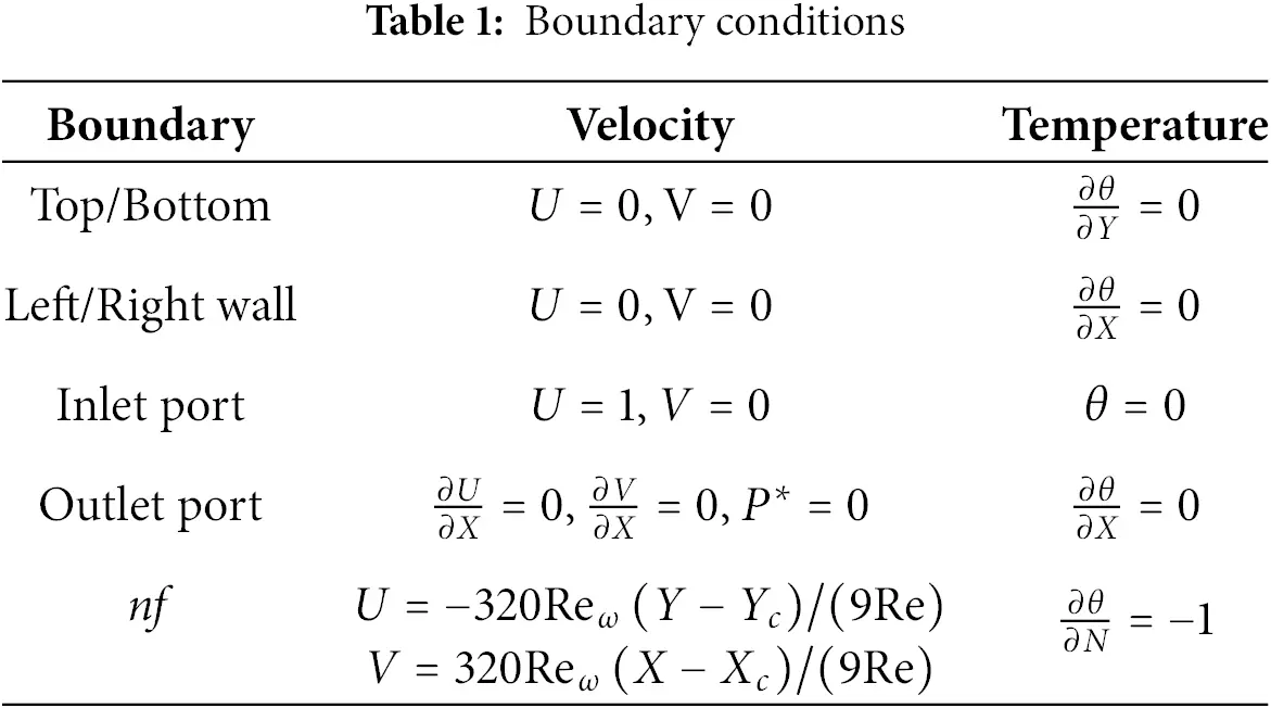
The physical configuration of the present study is shown in Fig. 1, representing a steady, two-dimensional, laminar flow of incompressible Cu–water nanofluid within a Γ−shape enclosure of length H=1m. Within the domain, N−circular cylinders, each having a uniform diameter of 0.15 m, are strategically positioned at different locations. The enclosure features an inlet and an outlet, both with a width of W=0.2m. The cold nanofluid enters the enclosure through the inlet situated at the bottom-left corner (0, W), with a constant inflow velocity Uin and an initial temperature Tin. The outlet is located near the top-right corner of the domain (1,1−W). All walls of the enclosure are assumed to be adiabatic and adhere to no-slip boundary conditions illustrated in Table 1. Each embedded cylinder is subjected to a uniform heat flux q′′ and rotates in the clockwise direction with a constant angular velocity ω. The numerical simulations are performed for a range of Reynolds numbers, Re=100−1000, rotational Reynolds numbers, Reω=0−100 and nanoparticle volume fractions, ϕ=0%−3%. Gravitational effects and viscous dissipation are neglected, and the thermophysical properties of the nanofluid are assumed constant throughout to simplify the model. Under these assumptions, the dimensionless governing equations for continuity, momentum, and energy conservation are established and solved to analyze the flow and heat transfer characteristics [33,34].
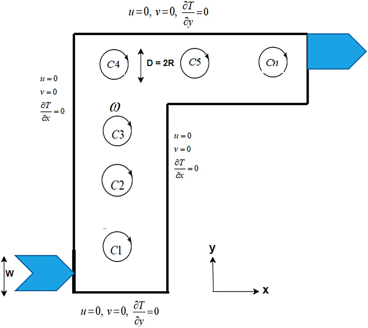
Figure 1: The schematic geometry
Continuity equation
∂u∂x+∂v∂y=0.(1)
Momentum equation
x-momentum equation
u∂u∂x+v∂u∂y=−1ρnf∂P∂x+μnfρnf(∂2u∂x2+∂2u∂y2).(2)
y-momentum equation
u∂v∂x+v∂v∂y=−1ρnf∂P∂y+μnfρnf(∂2v∂x2+∂2v∂y2).(3)
Energy equation
u∂T∂x+v∂T∂y=knf(ρcp)nf(∂2T∂x2+∂2T∂y2).(4)
With the Boundary conditions are
Top wall: u=0,v=0, ∂T∂y=0,
Bottom wall: u=0,v=0, ∂T∂y=0,
Left wall: u=0,v=0, ∂T∂x=0,
Right wall: u=0,v=0, ∂T∂x=0.
Inlet port: u=Uin,v=0, T=Tin,
Outlet port: ∂u∂x=0,∂v∂x=0,P=Pout, ∂T∂x=0.
Rotating cylinder: u=−ω(y−yc),v=ω(x−xc).
Using the similarity transformation
X=xH,Y=yH,U=uUin,V=vUin,θ=T−Tinq′′H/Knf,P∗=PUin2ρnf.
The following dimensionless equations can be described:
∂U∂X+∂V∂Y=0,(5)
U∂U∂X+V∂U∂Y=−∂P∗∂X+WHRe(∂2U∂X2+∂2U∂Y2),(6)
U∂V∂X+V∂V∂Y=−∂P∗∂Y+WHRe(∂2V∂X2+∂2V∂Y2),(7)
U∂θ∂X+V∂θ∂Y=WHRePr(∂2θ∂X2+∂2θ∂Y2),(8)
where
Re =ρnfUinWμnf Reynolds number, Pr=μnfcpnfKnf Prandtl number, Reω=ρnfωR2μnf Rotational Reynolds number.
The Nusselt number is calculated using the following expression.
Nu=hDKnf=2π(DH)∫02πθsdθ.(9)
Model for nanofluids is listed below [35–37].
Viscosity: μnf=μf(1−ϕ)2.5(10)
Density: ρnf=(1−ϕ)ρf+ϕρp(11)
Heat Capacity: (ρcp)nf=(1−ϕ)(ρcp)f+ϕ(ρcp)p(12)
Thermal Conductivity: knf=kf[(kp+2kf)−2ϕ(kf−kp)(kp+2kf)+2ϕ(kf−kp)](13)
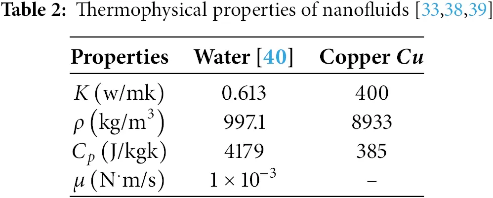
The thermophysical properties of the base fluid and nanoparticles are listed in Table 2.
Finite Element Formulation
In this study, the primary advantages of using the Finite Element Method (FEM) in COMSOL are its ability to handle complex, Multiphysics problems by integrating various physical phenomena, accuracy in simulating various engineering scenarios, reducing time and cost in product development by minimizing the need for physical prototypes, and providing detailed insights into system behavior, which helps in optimizing designs and making informed decisions. The governing Eqs. (6)–(8) are solved using the Galerkin finite element method. The six-node triangular element is employed, with linear interpolation assumed for the field variables: the velocity components (U,V), the pressure (P), and the temperature (θ). These are expressed as follows:
U(X,Y)=NαUα,V(X,Y)=NαVα,θ(X,Y)=Nαθα,P(X,Y)=HλPλ(14)
where Nα,Hλ indicate the nodal shape functions of the elements. The nonlinear residual equations at the interior nodes of domain A are obtained by applying the Galerkin weighted-residual method to Eqs. (6)–(8) and integrating the diffusive terms by parts:
Ri(1)=∫ANα(∂U∂X+∂V∂Y)dA(15)
Ri(2)=∫ANα(U∂U∂X+V∂U∂Y)dA+∫AHλ(∂P∂X)dA+WHRe∫A(∂Nα∂X∂U∂X+∂Nα∂Y∂U∂Y)dA−∫S0NαSXdS0(16)
Ri(3)=∫ANα(U∂V∂X+V∂V∂Y)dA+∫AHλ(∂P∂Y)dA+WHRe∫A(∂Nα∂X∂V∂X+∂Nα∂Y∂V∂Y)dA−∫S0NαSYdS0(17)
Ri(4)=∫ANα(U∂θ∂X+V∂θ∂Y)dA+WHPrRe∫A(∂Nα∂X∂θ∂X+∂Nα∂Y∂θ∂Y)dA−∫SwNαqwdSw(18)
where A is the element area. Inserting the element distributions for velocity, temperature, and pressure leads to the finite element system that can be written as follows:
FαP=KαβXUβ+KαβYVβ(19)
FαU=KαβγXUβUγ+KαβγYUβVγ+MαμXPμ+WHRe(SαβXX+SαβYY)Uβ−Qαu(20)
FαV=KαβγVUβVγ+KαβγYVβVγ+MαμYPμ+WHRe(SαβXX+SαβYY)Vβ−Qαv(21)
Fαθ=KαβγXUβθγ+KαβγYVβθγ+WHPrRe(SαβXX+SαβYY)θβ−Qαθ(22)
where
KαβX=∫ANαNβ,XdA KαβY=∫ANαNβ,YdA KαβγX=∫ANαNβNγ,XdA
KαβγY=∫ANαNβNγ,YdA Kαβ=∫ANαNβdA SαβXX=∫ANα,XNβ,XdA
SαβYY=∫ANα,YNβ,YdA MαμX=∫AHαHμ,XdA MαμY=∫AHαHμ,YdA
Qαu=∫S0NαSXdS0 Qαv=∫S0NαSYdS0 Qαθ=∫SwNαqwdSw
The system of nonlinear algebraic equations is resolved through Newton–Raphson iterations conducted until convergence.
3 Result and Discussion
This section presents the numerical results for streamlines, isotherms, and fluid flow patterns to analyze the effect of rotating cylinders on the flow dynamics and thermal performance in a Γ-shaped enclosure filled with Cu-Water nanofluid. The simulations are conducted using COMSOL Multiphysics 6.3, with a fixed Reynolds number of Re=600 and a constant Prandtl number of Pr=5.4082, corresponding to the thermophysical properties of the nanofluid. The rotational Reynolds number (Reω) is varied as 0 and 100 to capture the influence of rotation, while the nanoparticle volume fraction is fixed at ϕ=3% various configurations with different numbers and placements of rotating cylinders are investigated to understand their impact on flow circulation and convective heat transfer. For each scenario (Table 3), the flow structure is visualized through streamlines, the temperature distribution is depicted by isotherms, and the velocity field is illustrated using fluid flow contours. Figs. 2–35 provide visual representations of the observed phenomena. The combined effects of rotation and nanoparticle dispersion are further validated through ANN, confirming the accuracy and predictive strength of the numerical simulations.
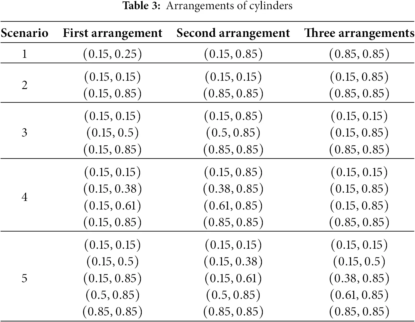
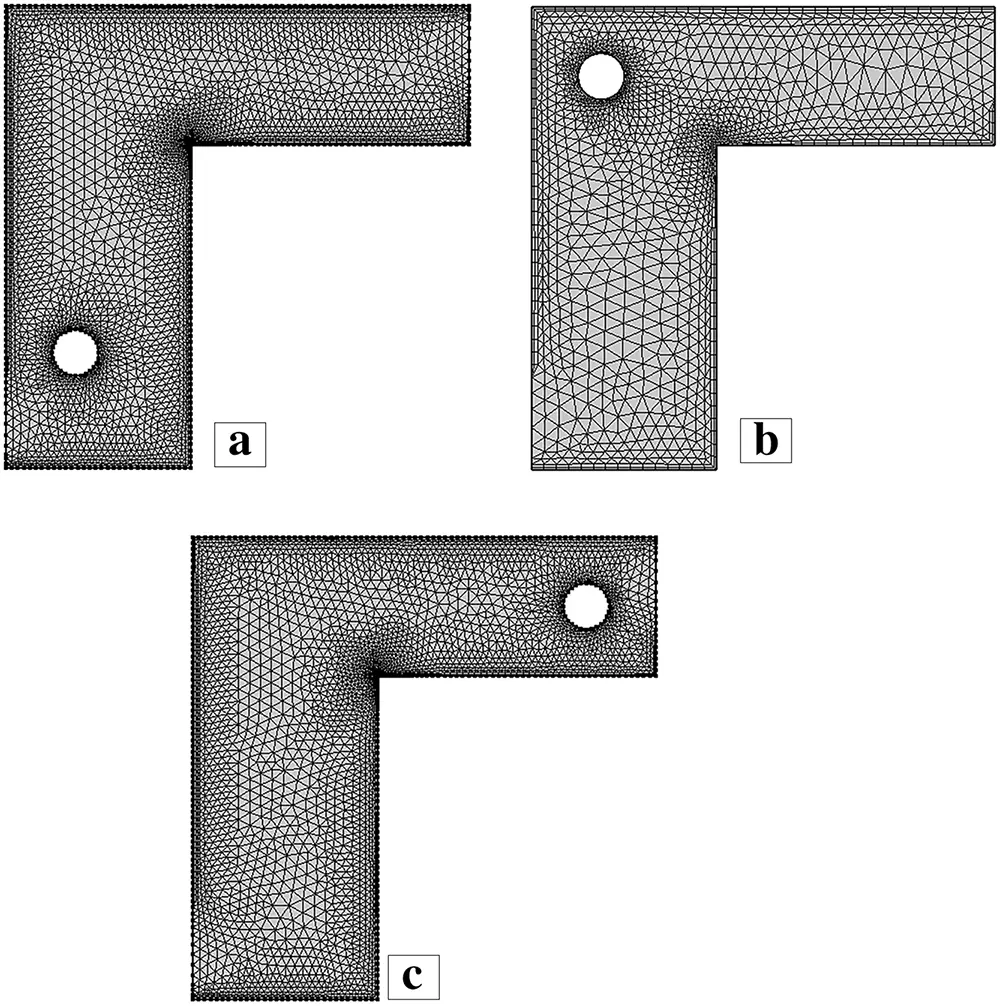
Figure 2: Mesh generation of one cylinder at three different placements
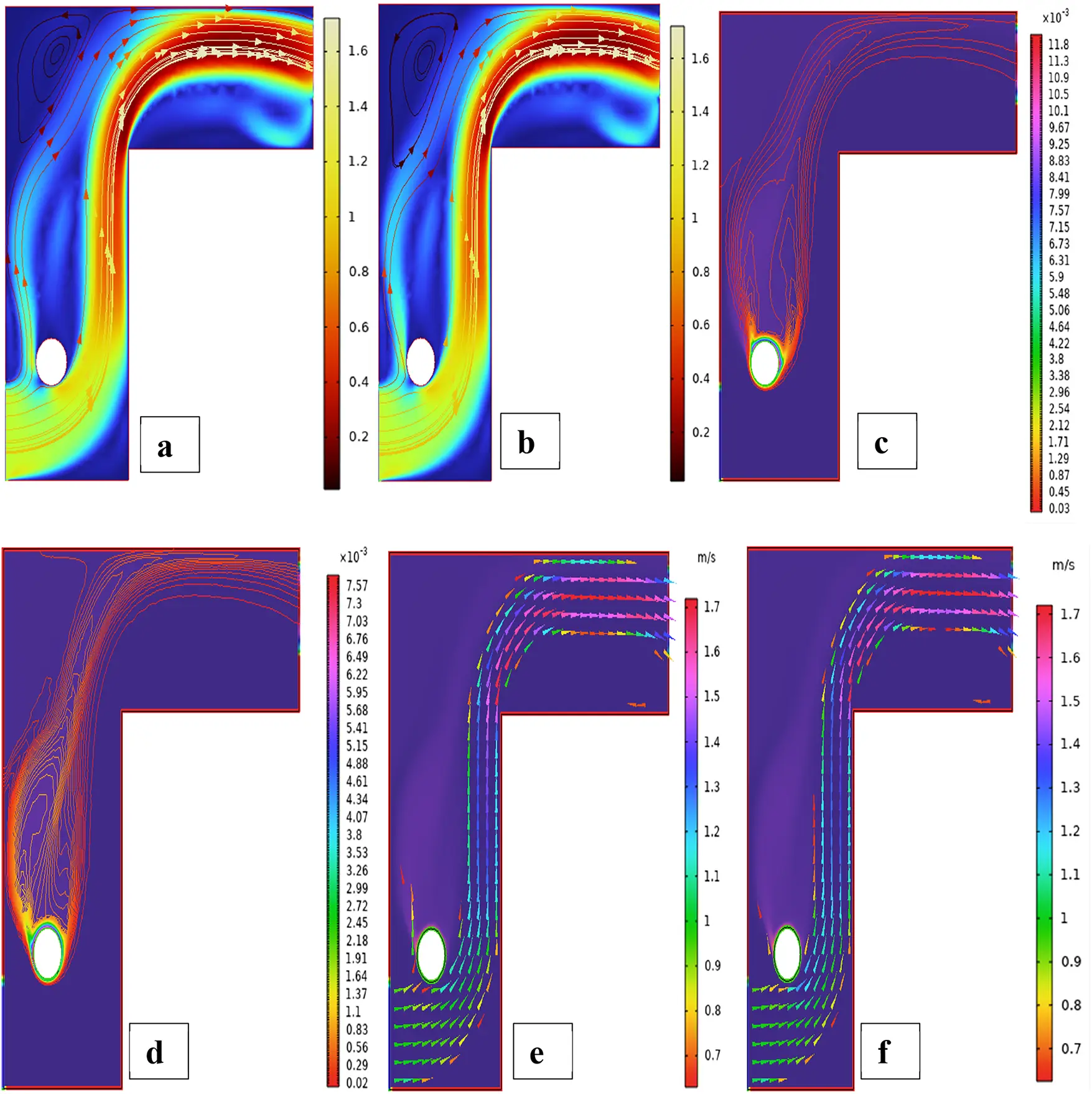
Figure 3: Streamlines (a,b), isotherms (c,d) and fluid flow (e,f) for a single cylinder at first arrangement

Figure 4: (a) ANN training, (b) Performance, (c) Error histogram, and (d) Regression for a single cylinder at the first arrangement
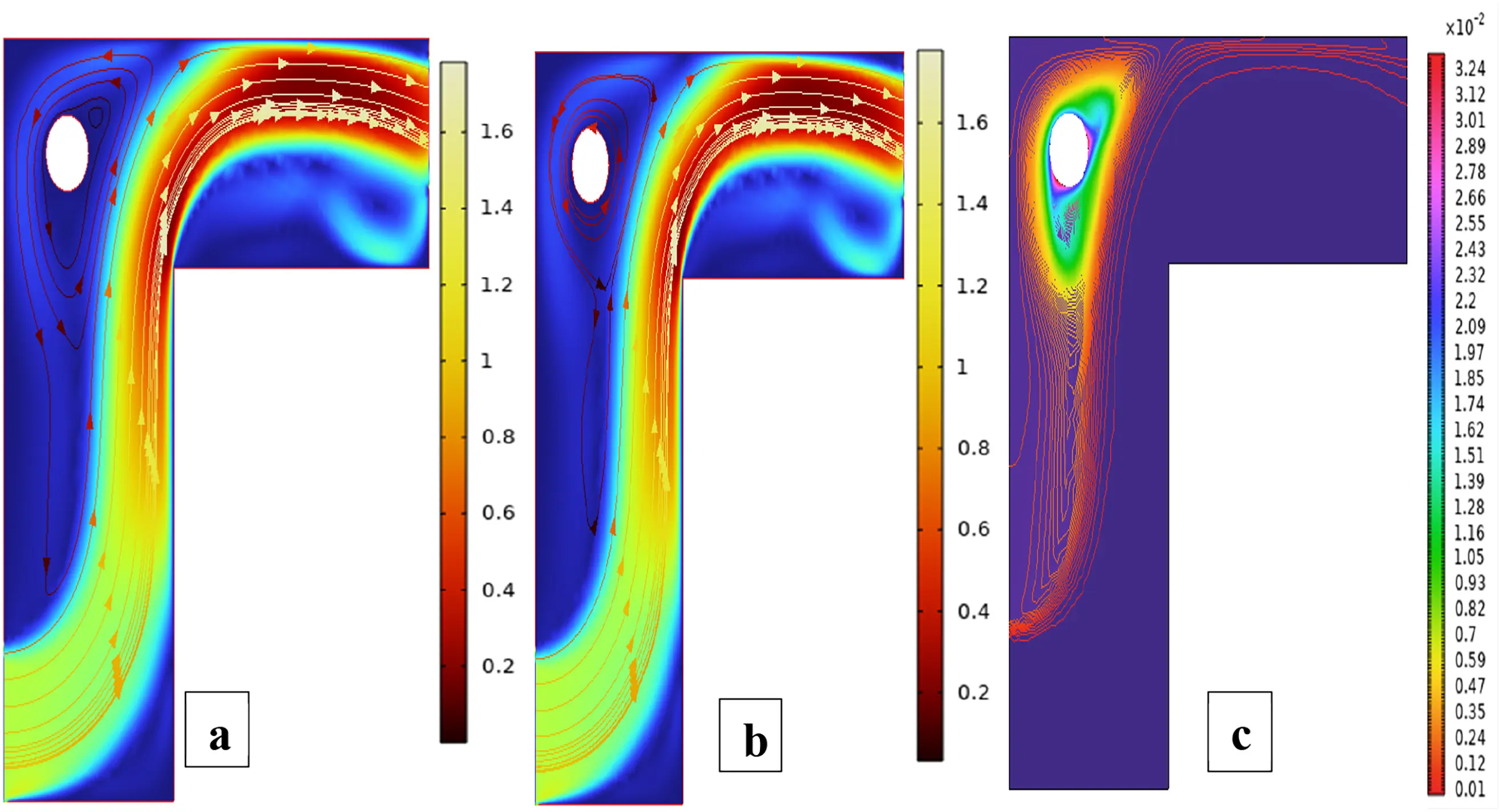
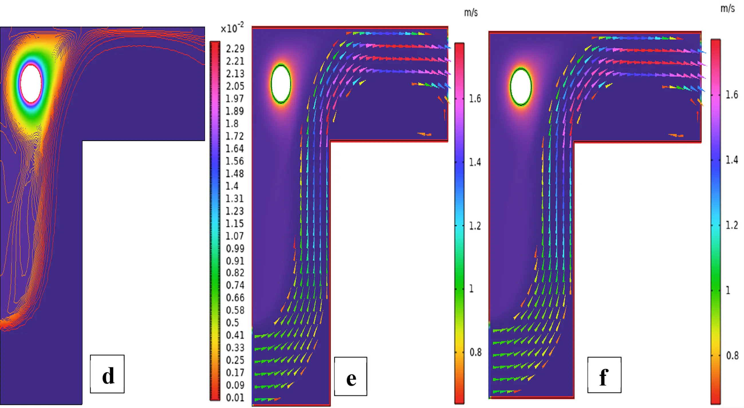
Figure 5: Streamlines (a,b), isotherms (c,d) and fluid flow (e,f) for a single cylinder at the second arrangement


Figure 6: (a) ANN training, (b) Performance, (c) Error histogram, and (d) Regression for single cylinders at the second arrangement
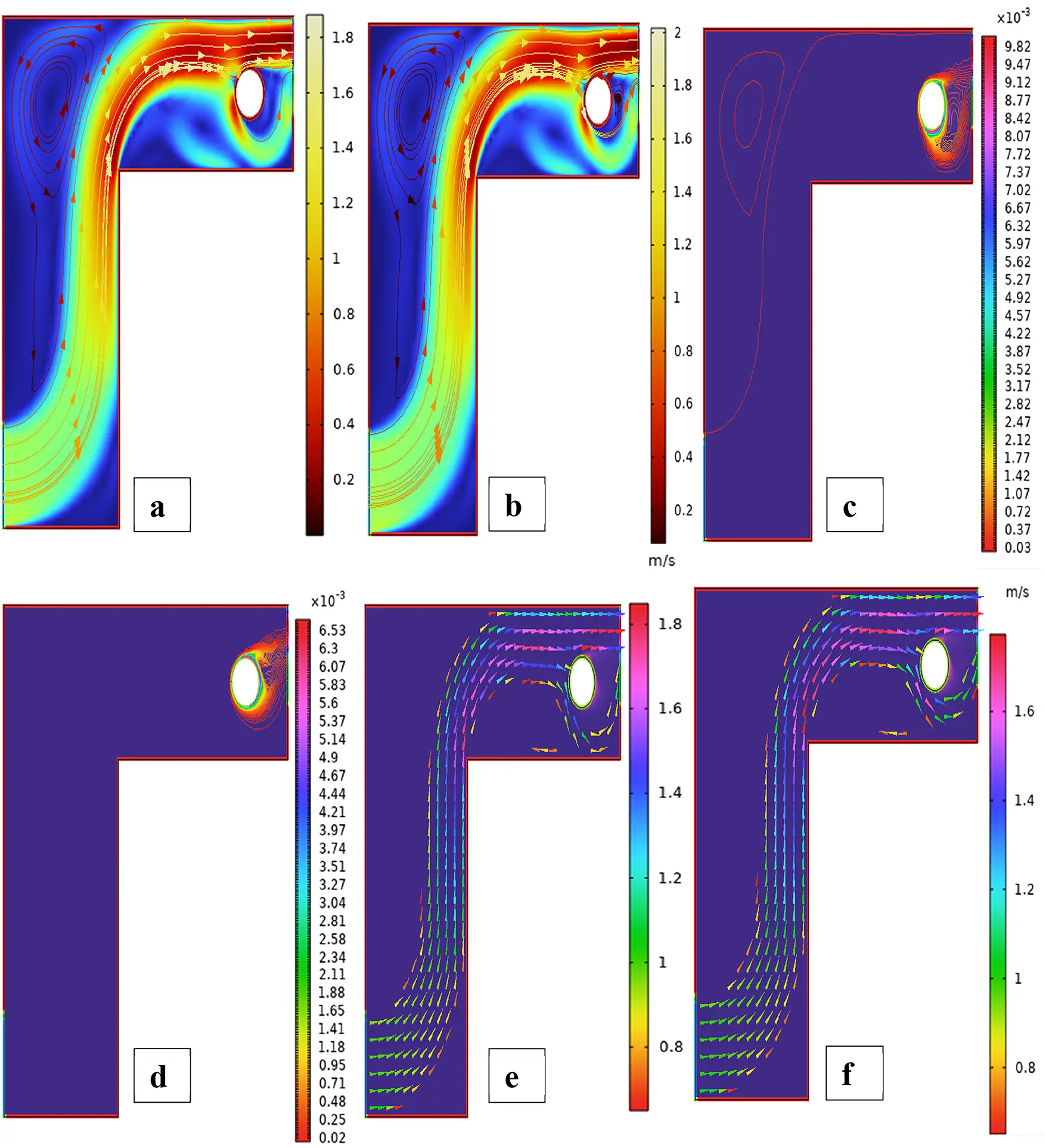
Figure 7: Streamlines (a,b), isotherms (c,d) and fluid flow (e,f) for single cylinders at third arrangement
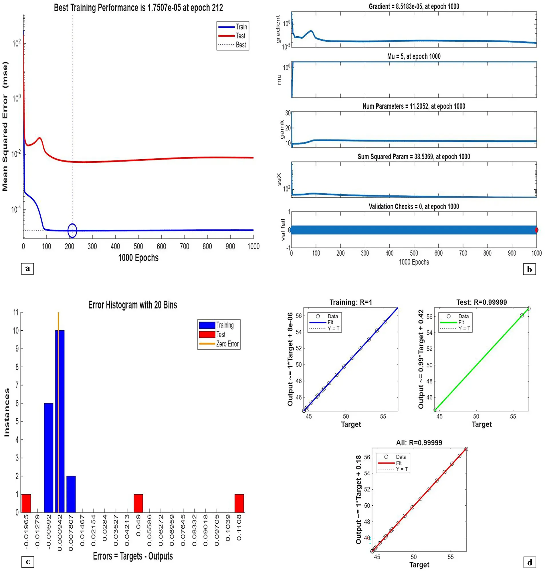
Figure 8: (a) ANN training, (b) Performance, (c) Error histogram, and (d) Regression for single cylinders at the third arrangement
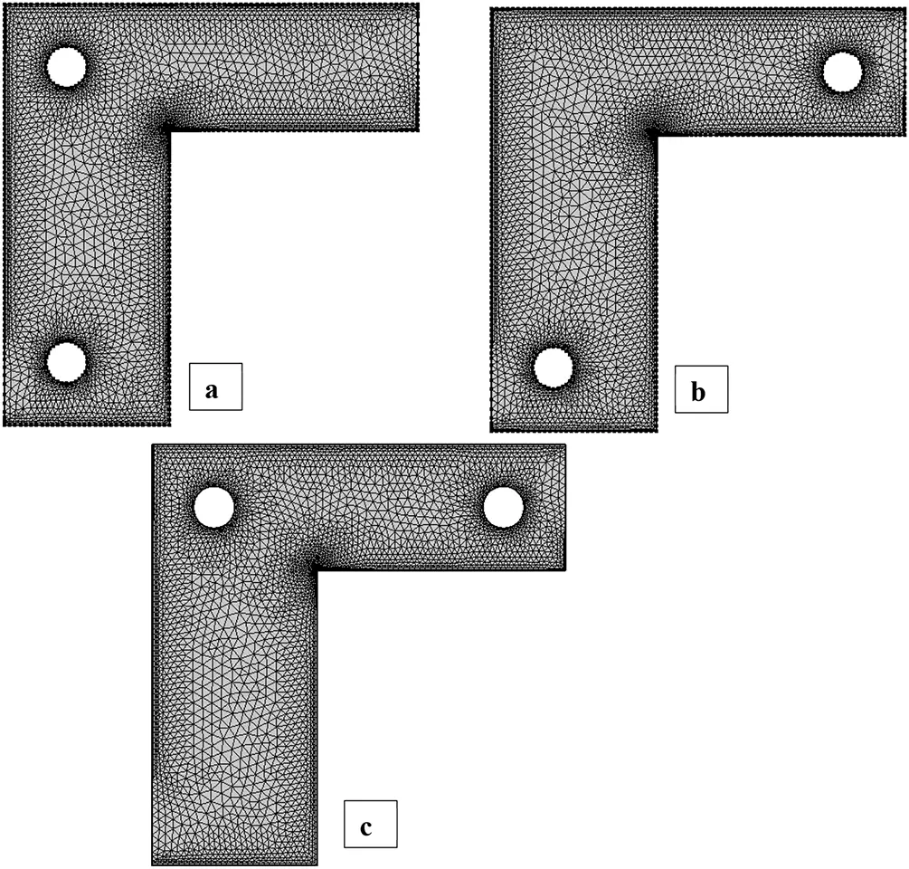
Figure 9: Mesh generation of two cylinders at three different placements
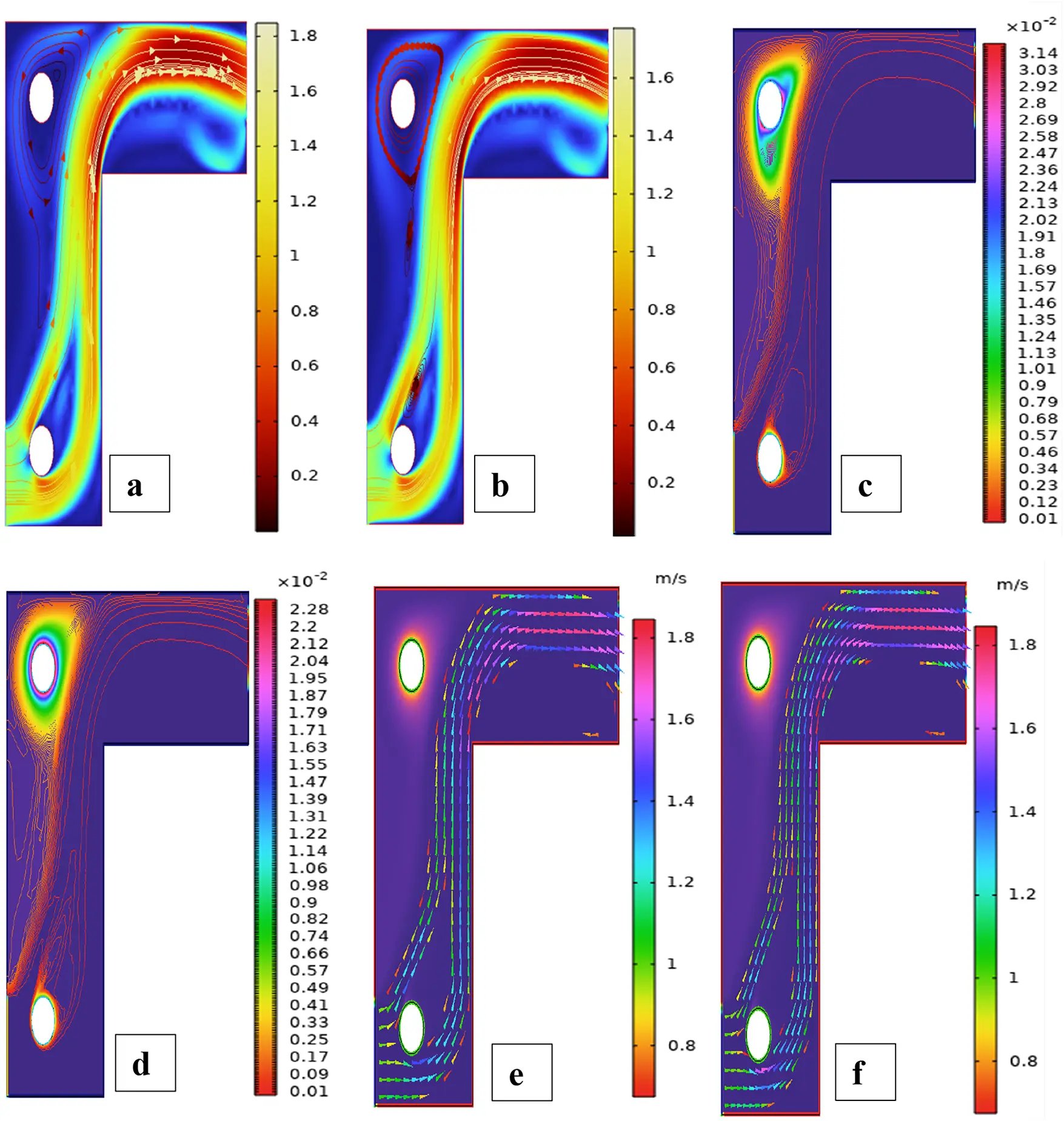
Figure 10: Streamlines (a,b), isotherms (c,d) and fluid flow (e,f) for two cylinders in the first arrangement

Figure 11: (a) ANN training, (b) Performance, (c) Error histogram, and (d) Regression for two cylinders at first arrangement
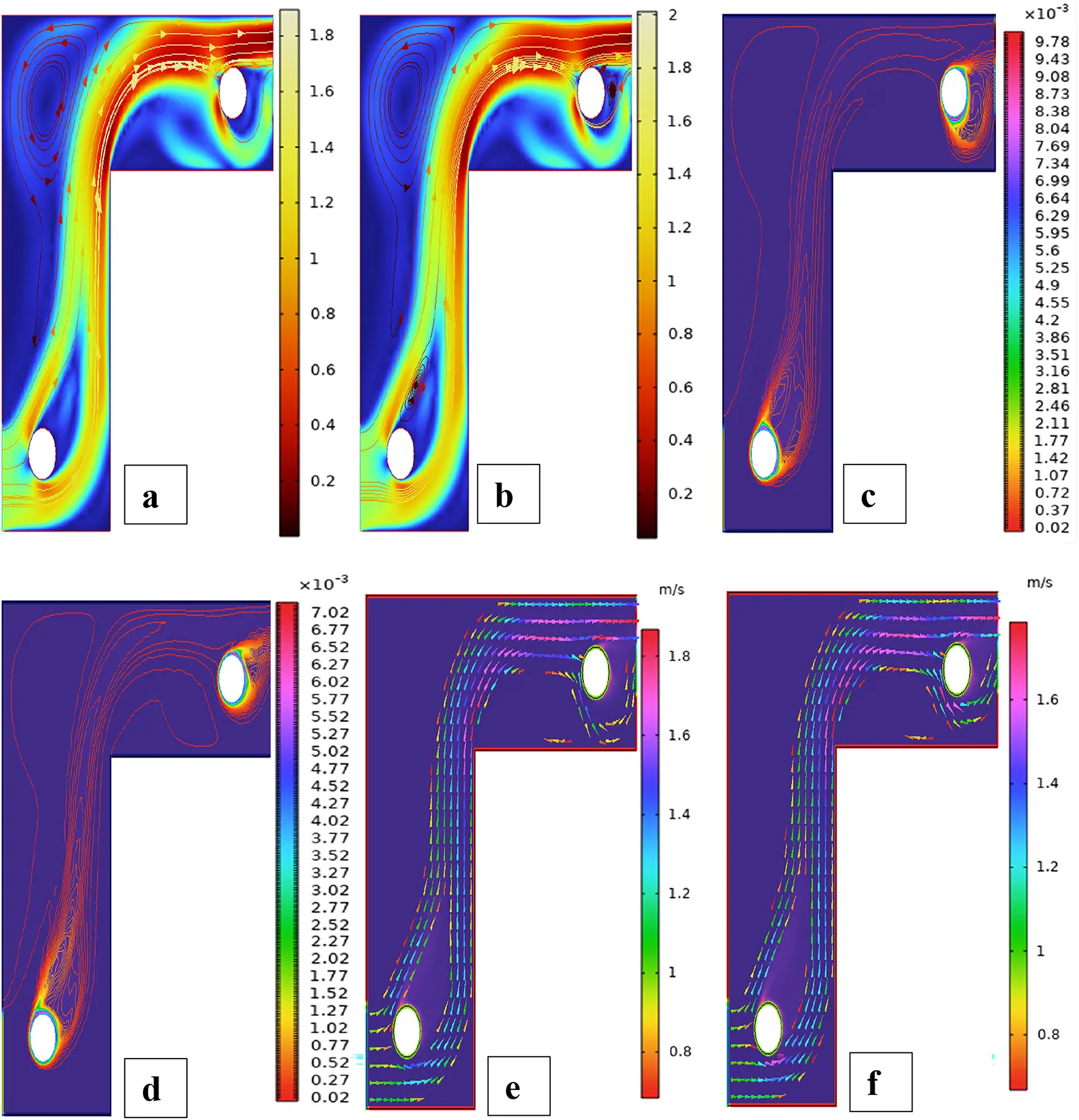
Figure 12: Streamlines (a,b), isotherms (c,d), and fluid flow (e,f) for two cylinders at the second arrangement

Figure 13: (a) ANN training, (b) Performance, (c) Error histogram, and (d) Regression for two cylinders at the second arrangement

Figure 14: Streamlines (a,b), isotherms (c,d) and fluid flow (e,f) for two cylinders at the third arrangement

Figure 15: (a) ANN training, (b) Performance, (c) Error histogram, and (d) Regression for two cylinders at the third arrangement

Figure 16: Mesh generation of three cylinders at three different placements


Figure 17: Streamlines (a,b), isotherms (c,d), and fluid flow (e,f) for three cylinders at the first arrangement

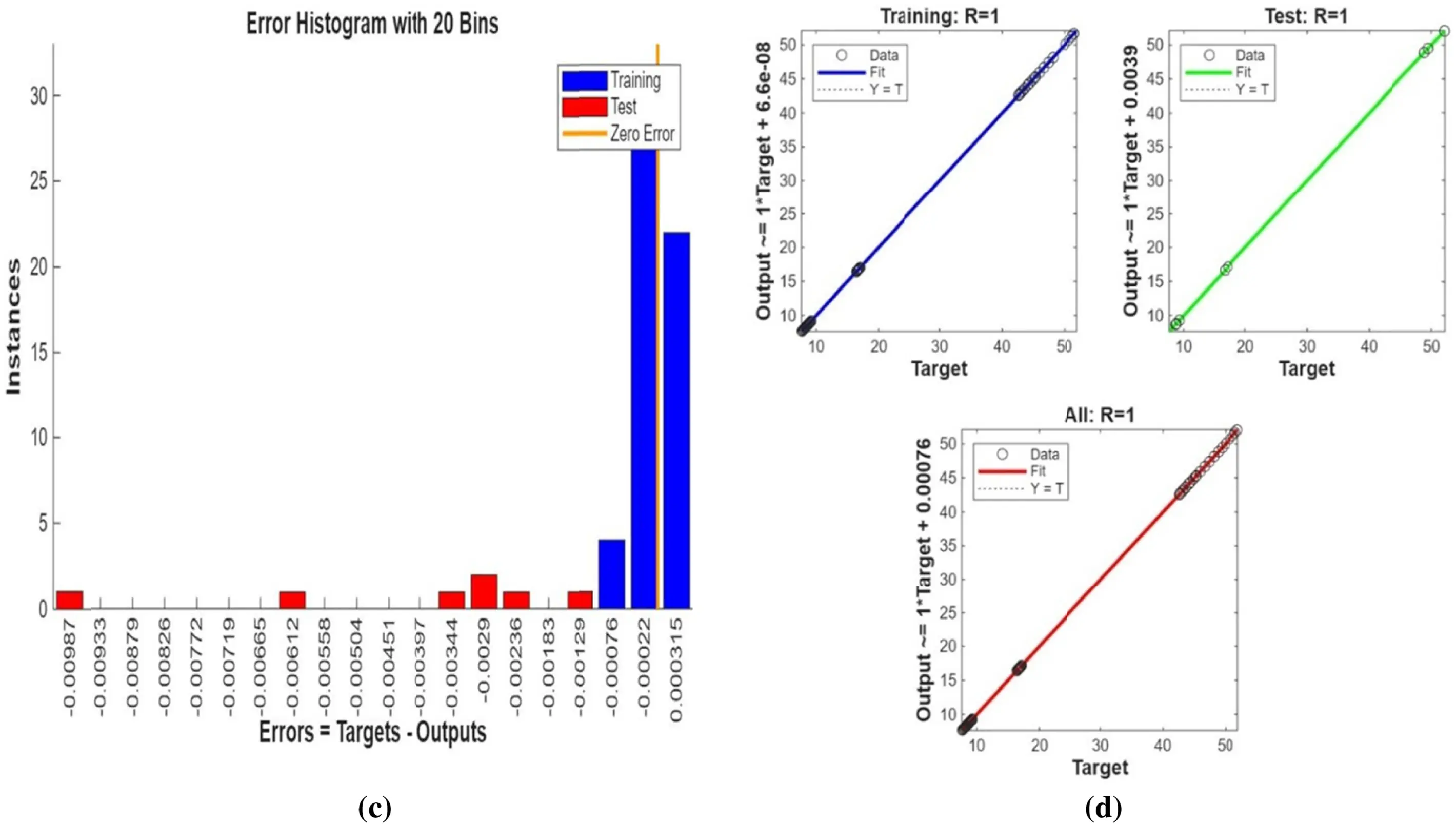
Figure 18: (a) ANN training, (b) Performance, (c) Error histogram, and (d) Regression for three cylinders at the first arrangement


Figure 19: Streamlines (a,b), isotherms (c,d), and fluid flow (e,f) for three cylinders at the second arrangement


Figure 20: (a) ANN training, (b) Performance, (c) Error histogram, and (d) Regression for three cylinders at the second arrangement

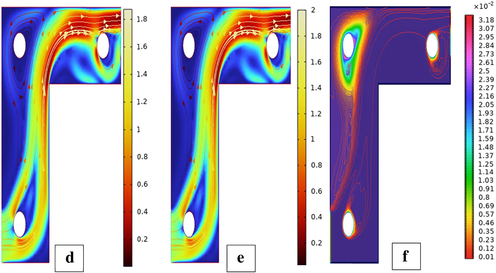
Figure 21: Streamlines (a,b), isotherms (c,d), and fluid flow (e,f) for three cylinders at the third arrangement

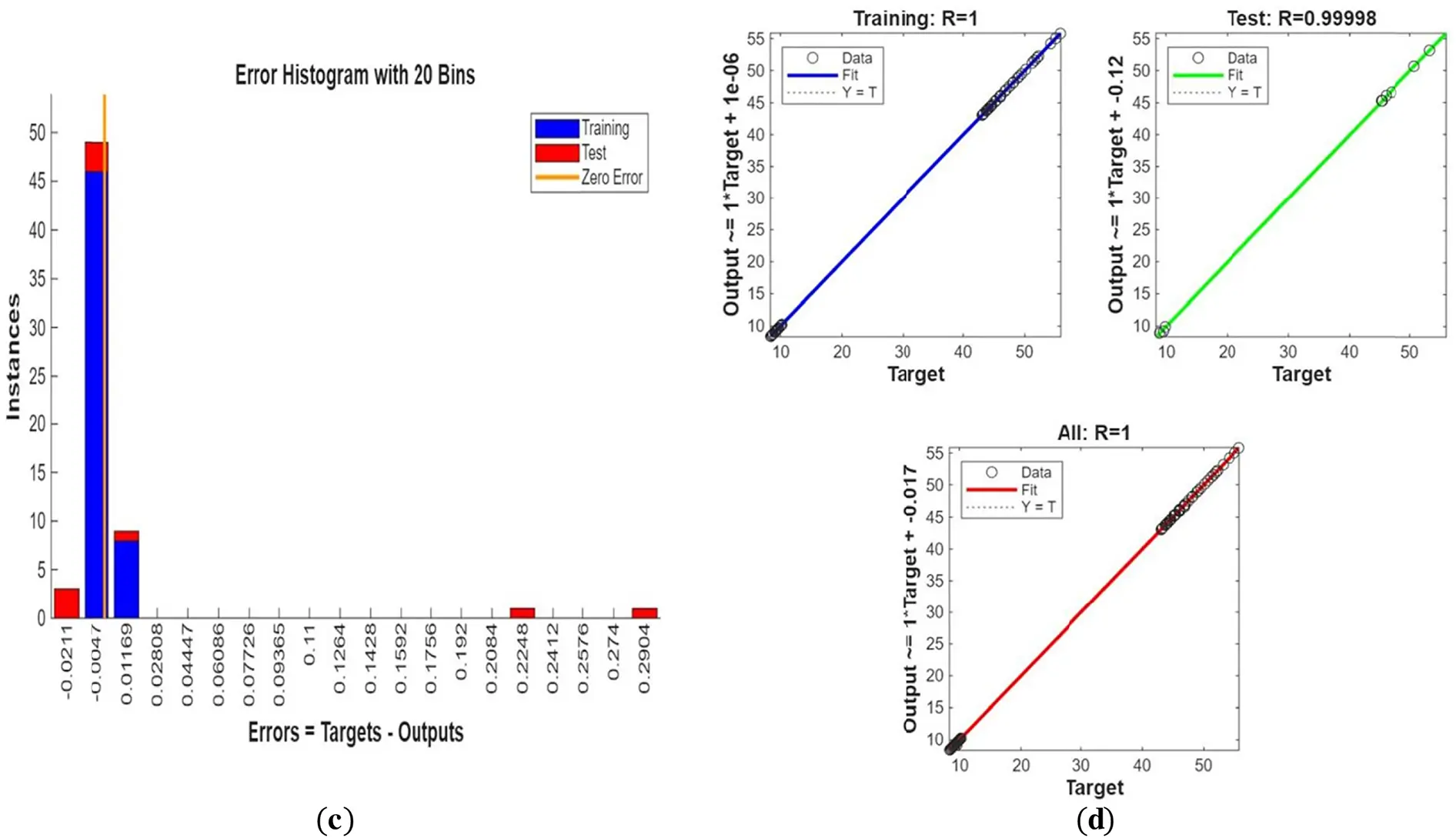
Figure 22: (a) ANN training, (b) Performance, (c) Error histogram, and (d) Regression for three cylinders at the third arrangement
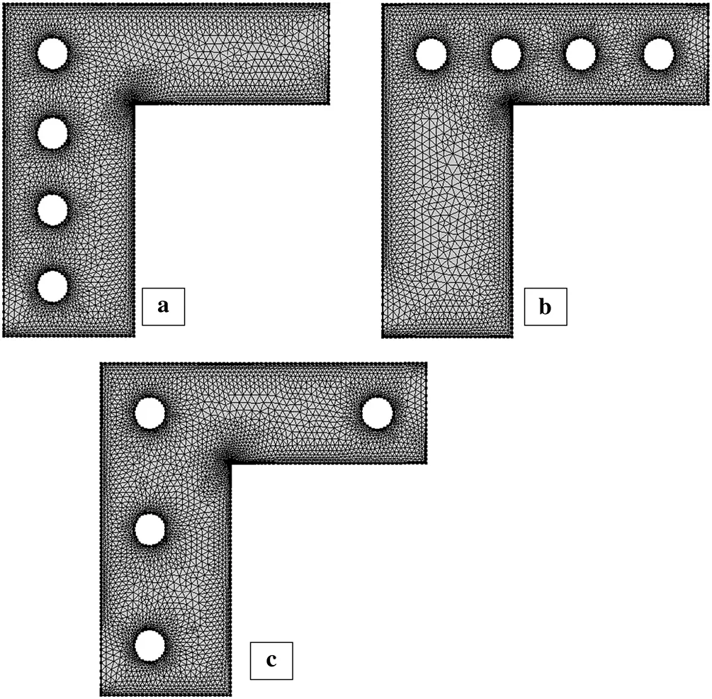
Figure 23: Mesh generation of four cylinders at three different placements

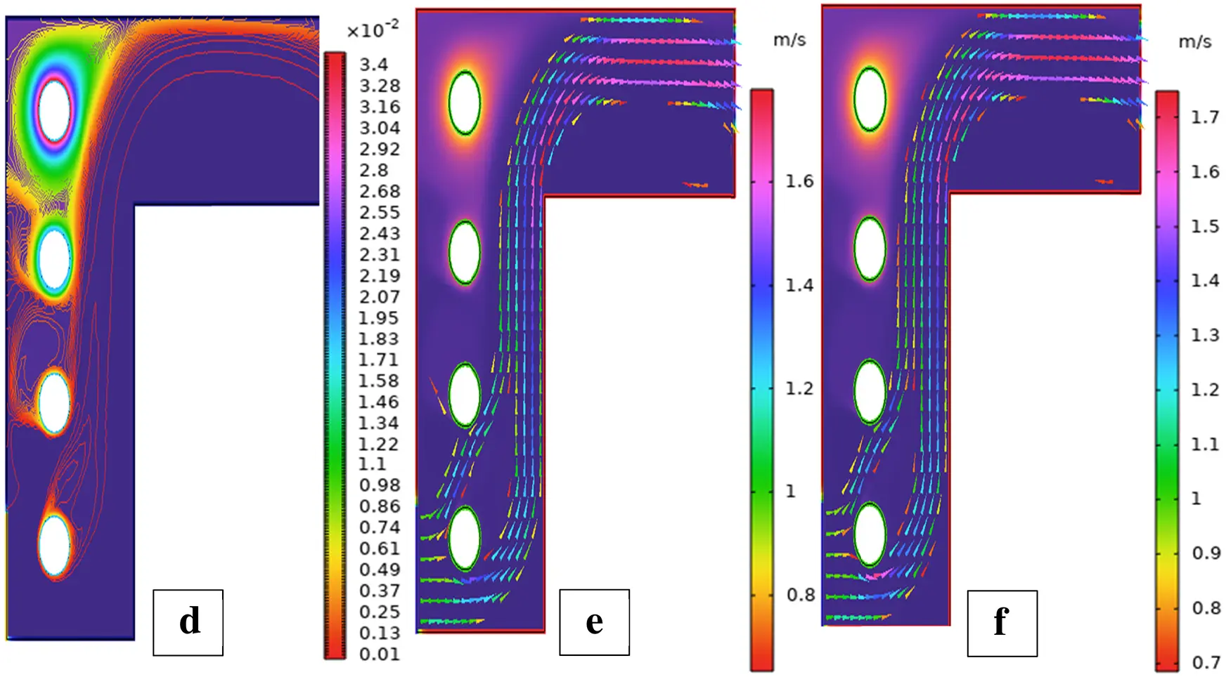
Figure 24: Streamlines (a,b), isotherms (c,d), and fluid flow (e,f) for four cylinders at the first arrangement

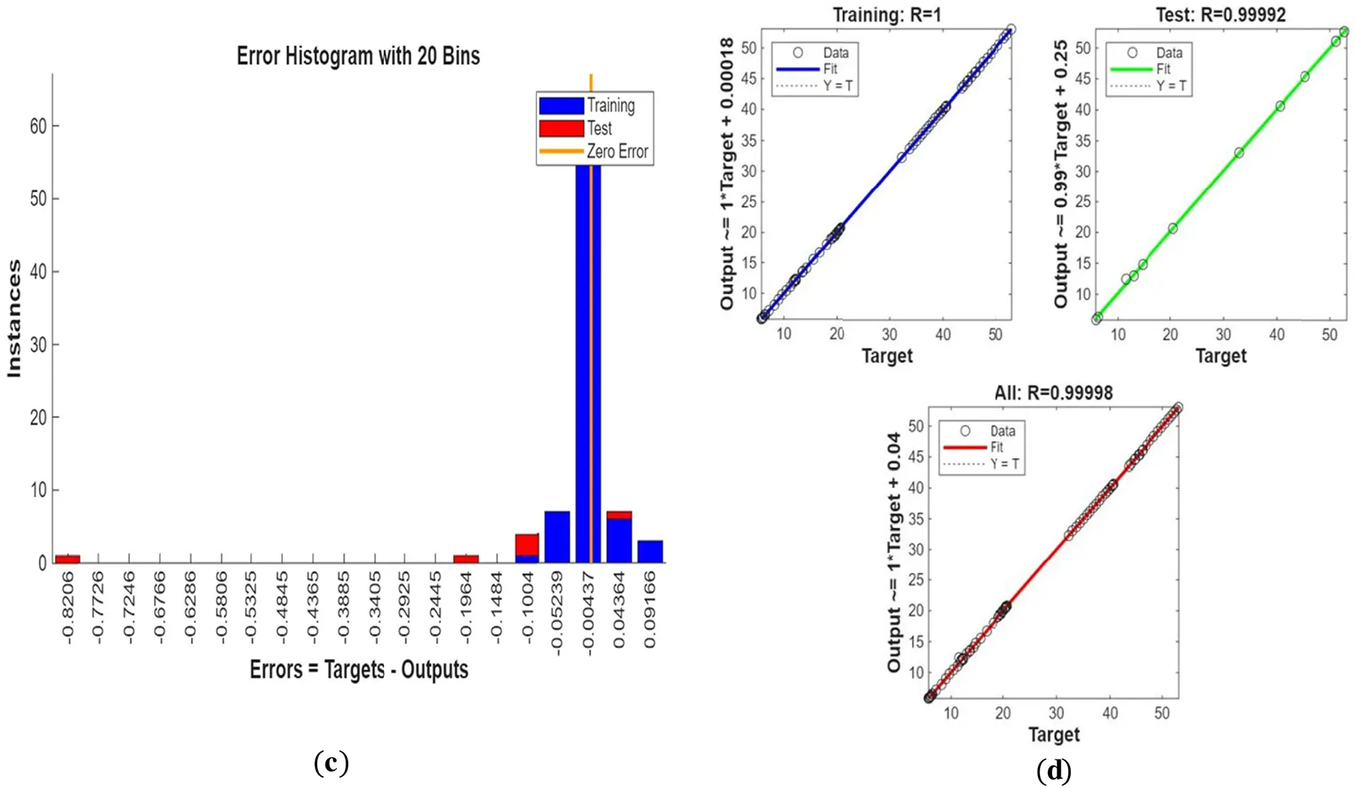
Figure 25: (a) ANN training, (b) Performance, (c) Error histogram, and (d) Regression for four cylinders at the first arrangement


Figure 26: Streamlines (a,b), isotherms (c,d), and fluid flow (e,f) for four cylinders at the second arrangement


Figure 27: (a) ANN training, (b) Performance, (c) Error histogram, and (d) Regression for four cylinders at the second arrangement

Figure 28: Streamlines (a,b), isotherms (c,d), and fluid flow (e,f) for four cylinders at the third arrangement

Figure 29: (a) ANN training, (b) Performance, (c) Error histogram, and (d) Regression for four cylinders at the third arrangement
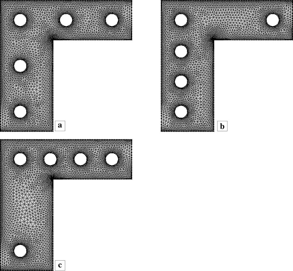
Figure 30: Mesh generation of five cylinders at three different placements


Figure 31: Streamlines (a,b), isotherms (c,d), and fluid flow (e,f) for five cylinders at the first arrangement

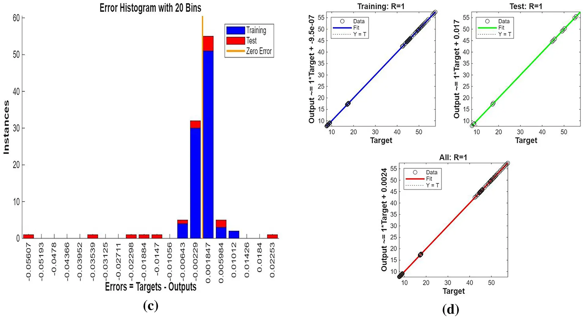
Figure 32: (a) ANN training, (b) Performance, (c) Error histogram, and (d) Regression for five cylinders at the first arrangement
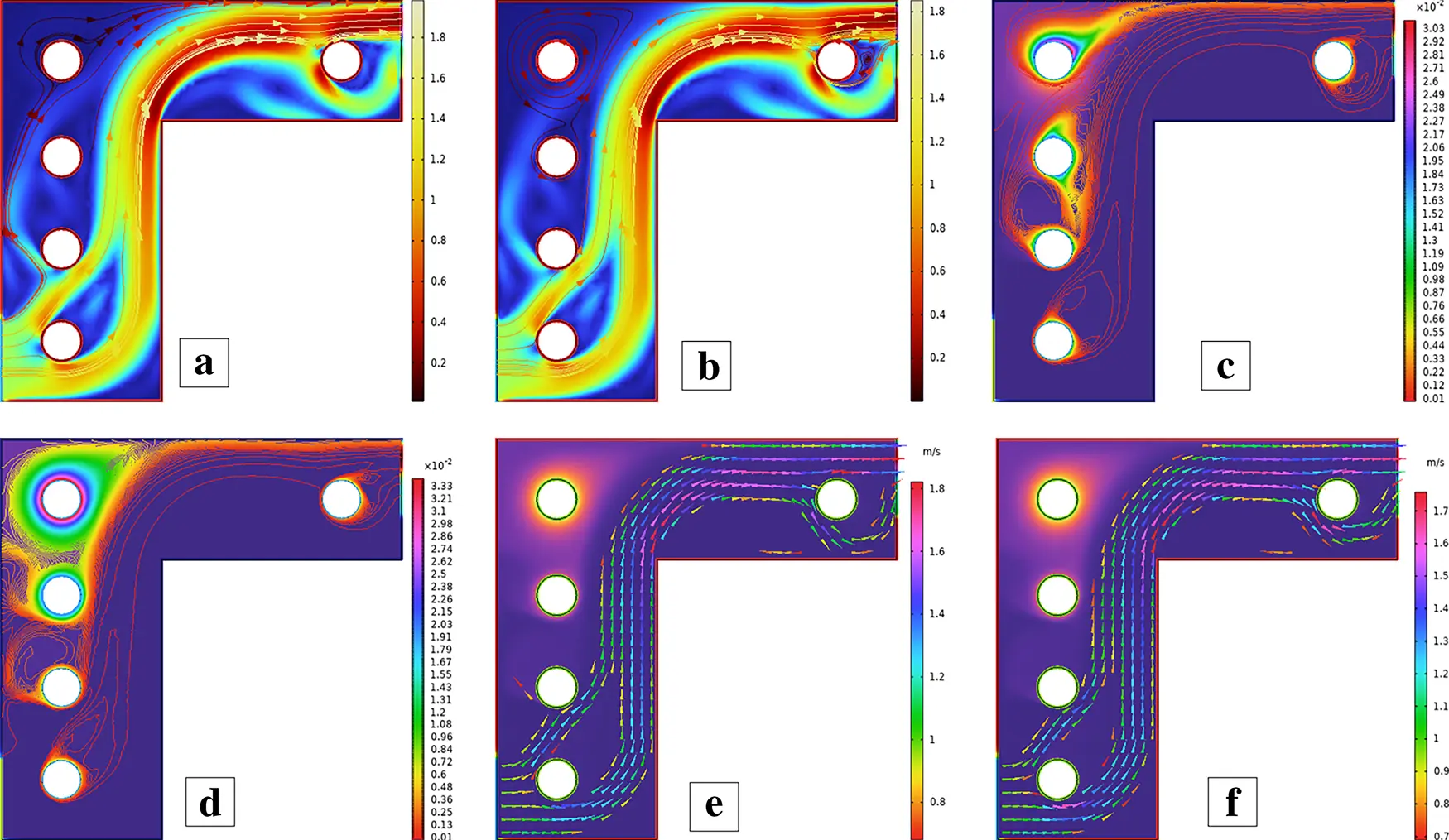
Figure 33: Streamlines (a,b), isotherms (c,d), and fluid flow (e,f) for five cylinders at the second arrangement
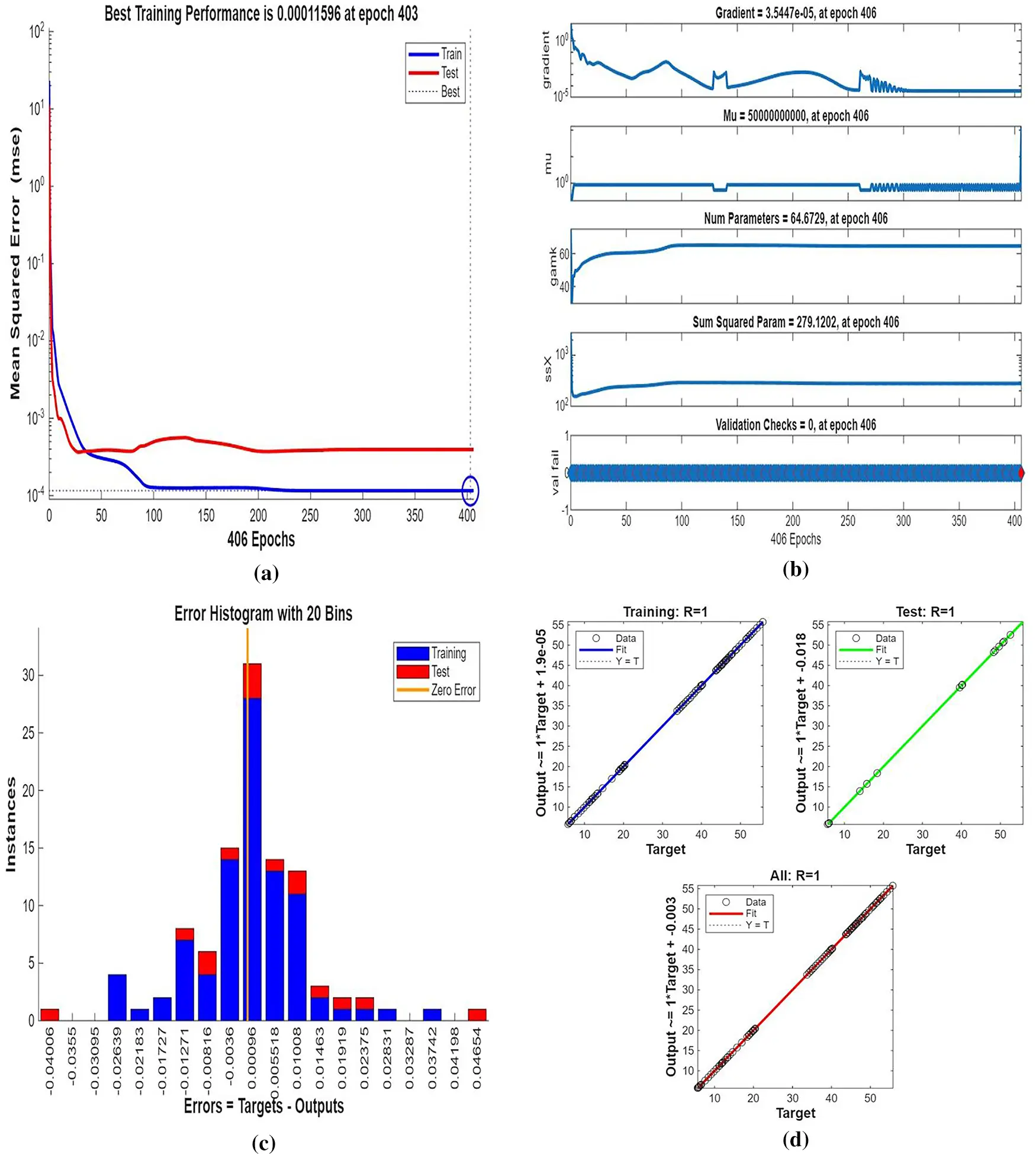
Figure 34: (a) ANN training, (b) Performance, (c) Error histogram, and (d) Regression for five cylinders at the second arrangement
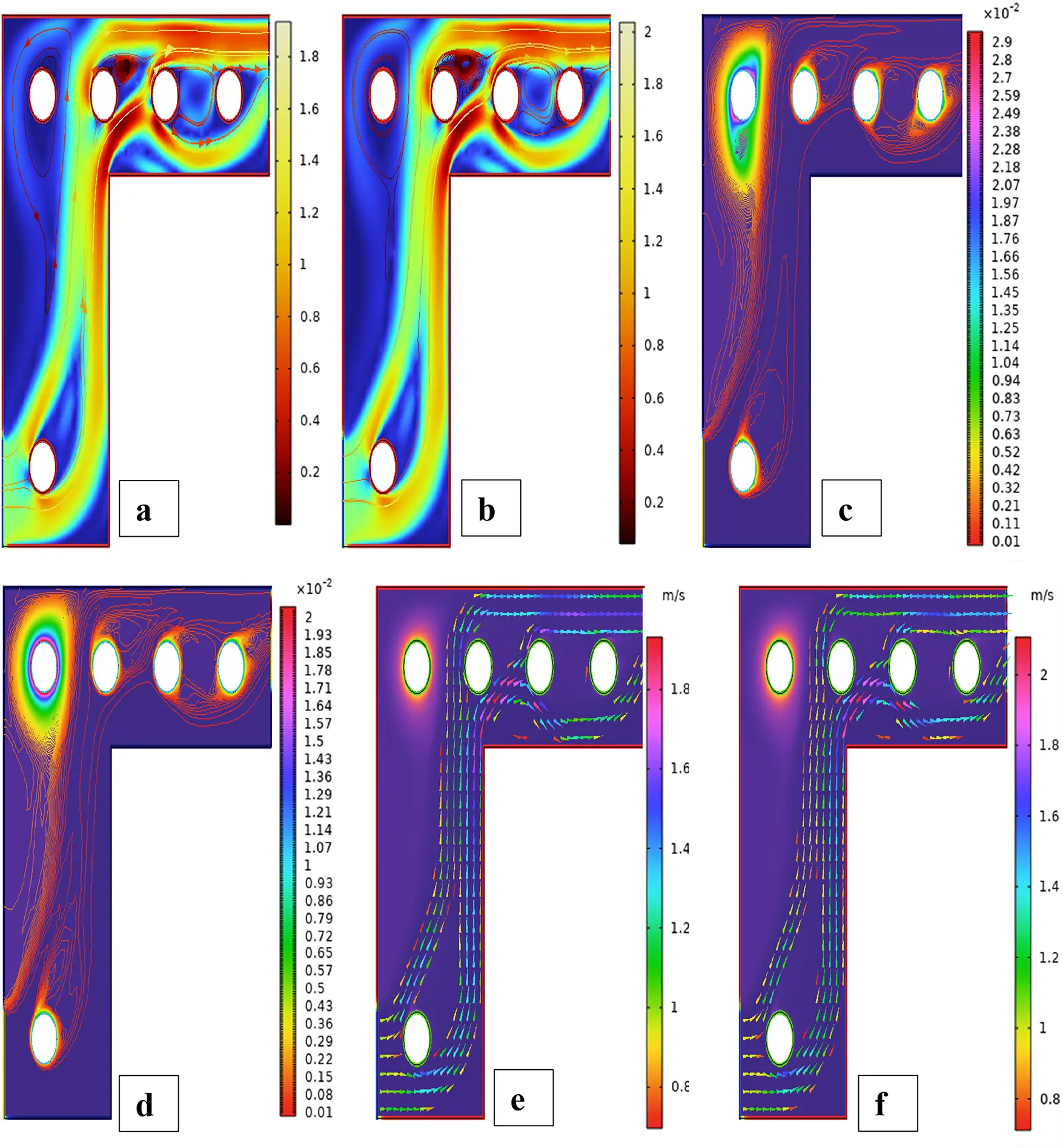
Figure 35: Streamlines (a,b), isotherms (c,d), and fluid flow (e,f) for five cylinders at the third arrangement
Scenario 1: One Cylinder Effect of Placement on Flow and Heat Transfer
Fig. 2 depicts the Mesh generation of a single cylinder in three locations in the Γ-shaped enclosure. Fig. 2a shows the mesh distribution in the case that the cylinder is placed close to the lower horizontal wall of the cavity, where close elements are clustered on the surface and near the cylinder to solve severe velocity and temperature gradients. Fig. 2b shows the arrangement whereby the cylinder will be positioned near the inner junction of the two arms, which translates to finer triangular elements at the corner area of the converging flow to represent the complex flow interactions. The mesh set-up in the cases where the cylinder is placed next to the upper vertical wall (Fig. 2c) is that of a symmetric refinement, giving an accurate representation of the boundary-layer and the wake region.
First Arrangement
Fig. 3 shows streamline patterns, isothermal contours, and fluid flow visualizations of nanofluid flow around a single cylinder in the first configuration. The figures display the influence of the rotational Reynolds number on the creation of flow circulation, thermal layering, and velocity field behavior on the cylinder’s surface. From Fig. 3a of case 1 with a rotational Reynolds number Reω=0, the streamlines show a symmetric and stable convective flow common in pure buoyancy-driven flow. This is physically induced by the temperature difference between the hot element and the cold boundaries. When there is no heat supply, the local fluid is expanded and hence less dense, producing buoyancy forces that drive the lighter fluid upwards. Simultaneously, denser cooler fluid moves in to replace it, with a resulting constant convective cycle. The rotational Reynolds number being zero, there is no rotation or Coriolis force to generate secondary flows or asymmetry, and the resulting flow field is the one controlled by gravitation and thermal gradients alone. With no angular momentum, the streamline pattern does not get distorted and remains centered around the heat source. In Fig. 3b of case 1 with a rotational Reynolds number Reω=100, the streamline pattern exhibits noticeable asymmetry and distortion compared to the non-rotating case. This change is physically attributed to the influence of rotation, which introduces a Coriolis force that alters the natural buoyancy-driven flow. As the enclosure begins to rotate, the Coriolis effect acts perpendicular to the direction of fluid motion, causing the streamlines to tilt and skew from their original vertical orientation. This leads to the formation of secondary vortices and a shift of the primary circulation cell away from the center. The competition between buoyancy forces and rotational inertia modifies the convective structure, reducing symmetry and enhancing complexity in the streamline topology. In case 1, Fig. 3c, for rotational Reynolds number Reω=0 and isothermal condition, temperature contours are uniformly distributed along the vertical centerline of the enclosure. The uniform distribution indicates that the flow is fully forced by natural convection with no effect of rotation. The heat transfer is predominantly in the vertical direction due to the hot and cold wall temperature gradient. The isotherms show a typical trend in which the thermal boundary layers form near the walls, and the core flow possesses nearly uniform temperature. The physical reason behind the phenomenon is the absence of the Coriolis force, allowing pure buoyancy-driven flow to take place in predominance of the thermal distribution in the cavity. In case 1, Fig. 3d, under isothermal conditions with a rotational Reynolds number Reω=100, the temperature contours are skewed and deformed, especially in the direction of rotation. Unlike the symmetric pattern at Reω=0, the isotherms are tilted and squeezed on one side, which indicates enhanced convective mixing due to rotation. This distortion is caused by the action of the Coriolis force, imposing a second circulation within the enclosure. As a result, heat is conveyed faster throughout the domain, decreasing thermal resistance. The physical reason behind this phenomenon is that greater rotational motion increases the angular momentum of the fluid, thus interrupting the flow driven by buoyancy and increasing the transport of heat through convective rotational convection. In Fig. 3e of case 1, velocity vectors of the flow at a rotation Reynolds number Reω=0, the flow remains dominated by buoyancy and axisymmetric about the vertical axis. The streamlines are in an orderly convection structure with a strong central recirculation cell characteristic of natural convection when there is no rotation. As there is no effect of rotation, the Coriolis force is zero, and the velocity field varies only due to the thermal gradients. The physical reason for such a symmetric flow pattern is that in the absence of rotational effects (Reω = 0), the temperature-induced density variation is the only driving mechanism, and a stable and balanced natural convection regime happens. Fig. 3f, case 1, flow pattern of fluid for Reω=100, rotational Reynolds number, shows heavy deformation compared to the non-rotating case. The velocity vectors also show strong asymmetry and skewness, indicating that the rotation imposes a strong Coriolis effect, which distorts the natural convection pattern. The central vortex is distorted, and it is shifted, and secondary flows are observed near the boundaries. The physical cause is due to the Coriolis force brought on by rotation, deflecting the trajectories of the fluid and preventing the central upward buoyant plume. Thus, the flow will become rotary and redistribute heat and momentum in a non-vertical path, which means there is an interaction between rotational inertia and thermal buoyancy forces. Bayesian Regularization is utilized to simulate numerical outcomes of hybrid nanofluid flow within a single cylinder to investigate the predictive potential of ANNs depicted in Fig. 4. Fig. 4 illustrates insights into training dynamics, error distribution, fitting behavior, and regression fidelity. Fig. 4a shows the ANN training performance curve, where the mean squared error reduces drastically in early epochs, showing fast convergence. The alignment of training, validation, and test curves shows minimal overfitting and great generalization. This verifies the effectiveness of the Bayesian Regularization algorithm in simulating the physics of hybrid nanofluid flow over a cylindrical geometry. The error histogram as shown in Fig. 4b provides a plot of error distribution. The errors are uniformly spread around zero with a small deviation, which means that the network has high accuracy for the entire dataset. The bars’ piling up near zero highlights consistent performance without systemic bias in the predictions. Fig. 4c is the plot of the fit function of actual outputs and ANN-predicted outputs. The close proximity of predicted and actual values to the diagonal line indicates the good approximation ability of the ANN. The residuals are all uniformly small, which again shows the stability of the model after training. Fig. 4d shows training, validation, test, and overall data regression plots. The regression line shows a high relationship (R-value is close to 1) and indicates perfect linearity between predicted results and actual results. This validates the model’s performance in modeling the hybrid nanofluid under given flow and boundary conditions.
Second Arrangement
Fig. 5 illustrates the streamlines, isotherms, and flow patterns of nanofluid flow past an isolated cylinder under the second configuration. The results indicate how the changing location of the cylinder affects the flow separation, thermal boundary growth, and velocity profile at various rotational Reynolds numbers. In case 1, second arrangement Fig. 5a, the streamline pattern is provided for rotational Reynolds number Reω=0, where the cavity flow is caused by the top lid displacement and not by any rotation. The cylinder in this arrangement is placed off the geometric center, which significantly alters the symmetry of the flow compared to the first arrangement. Due to the off-center position of the cylinder, the central vortex is displaced and deformed around the cylinder to form an asymmetrical recirculation zone. Streamlines are compressed on the cylinder-side and bulged on the opposite side, illustrating the blockage effect of the eccentric cylinder. Physically, this results from the fact that the asymmetric alignment leads to uneven shear stresses, redistributing the vorticity and breaking the intrinsic symmetry of lid-driven flow, even without rotation. In case 1, second arrangement Fig. 5b, the streamline contours are depicted for rotational Reynolds number Reω=100, when the cylinder is in an off-center position within the cavity. Introducing cylinder rotation imposes significant Coriolis and centrifugal effects, having a powerful influence on the flow of fluid. As a result, multiple secondary vortices are generated around the rotating cylinder, and the initially predominant primary vortex gets forced out and distorted. The rotational motion causes a strong recirculation region close to the cylinder surface, increasing the flow’s complexity and making the streamlines wrap around the cylinder in a tighter, spiral manner. Physically, this is caused by the increased rotational inertia caused by the rotating cylinder, which increases the velocity gradients and results in the formation of more energetic and dynamic secondary flow structures. In Case 1, the second arrangement, Fig. 5c, isotherms are presented for rotational Reynolds number Reω=0, when the cylinder is stationary and asymmetrically placed within the cavity. In the absence of rotation effects, the thermal field will remain reasonably symmetric about the vertical axis of the cavity, and temperature gradients are dominated by buoyancy-driven natural convection. The cylinder is a passive barrier that disturbs the flow very little, and it generates very gentle thermal boundary layers over the surface. Physically, no additional shear or mixing drive is supplied to the fluid because the cylinder is not rotating, which limits the thermal dispersion and results in wider, uniformly distributed isotherms. Heat transfer is primarily by conduction near the cylinder and by convection in the bulk fluid, with no advantage usually provided by rotation. In case 1, the second arrangement, Fig. 5d, isothermal contours are shown for the rotational Reynolds number Reω=100, which corresponds to an off-center rotating cylinder within the cavity. The rotation creates strong shear forces and centrifugal actions, significantly disrupting the thermal field. As a result, the isotherms are highly deformed and asymmetric, packing more densely in the region near the cylinder surface due to enhanced local convection. Physically, the cylinder’s rotation creates secondary vortices that intensify extensive mixing of hot and cold regions; thus, the temperature gradient in the neighborhood of the wall and convective heat transfer are augmented. The fluid near the rotating cylinder gains angular momentum, which causes a more vigorous circulatory motion, which makes the thermal boundary layer thinner and stretches the isotherms towards the walls of the cavity. This trend highlights the dominant effect of rotation in augmenting heat spreading in the cavity. Case 1, second arrangement. Fig. 5e illustrates the fluid flow patterns for rotational Reynolds number Reω=0, i.e., the cylinder is stationary at a non-centered location within the cavity. The flow is purely due to buoyancy and natural convection in the absence of any rotation. Due to the asymmetric position of the cylinder, the flow streamlines have uneven circulation, a dominant single vortex being developed away from the cylinder, and secondary recirculation regions developing in the corner regions. Physically, the off-center position disrupts the geometric symmetry and causes an uneven thermal buoyancy force distribution. The asymmetry induces skewed velocity profiles and biases the flow towards the region with greater thermal influence. Lacking any rotational momentum to influence the velocity field, the circulation is reduced, and the flow is more stratified with temperature-driven buoyancy controlling over inertial forces. In case 1, the second arrangement, Fig. 5f, fluid flow structures for rotational Reynolds number Reω=100 are shown, with the cylinder in rotation in the off-centered direction. Rotation has a very strong impact in altering the flow structure by introducing additional momentum into the system. This is responsible for creating stronger and more complex vortical structures, particularly at the rotating cylinder. Physically, huge centrifugal and Coriolis forces resulting from the high rotational speed further enhance velocity gradients along the cylinder. This causes intensified recirculation zones with the flow detaching and reattaching even more aggressively. The asymmetry of the cylinder position also generates directional distortion in streamline patterns so that circulation cells become stretched and shifted towards the cavity corners. Overall, the combined action of rotation and buoyancy creates a more energetic and more turbulent flow regime compared to the case of stationarity. Fig. 6 illustrates the strength of the ANN in modeling hybrid nanofluid flow over a single cylinder, based on an alternate training arrangement. It provides a combined view of the training process, error trend, function approximation, and regression analysis. Fig. 6a shows the performance curve of the Bayesian Regularization ANN model, where mean squared error drops quickly and plateaus at a low value, showing quick convergence and very good predictive power. The nearly parallel trajectories of training, validation, and test errors confirm insignificant overfitting and a generalized model. Fig. 6b presents the error histogram, which is closely centered at zero with small spread, indicating small deviation of predicted and actual outputs. This tight distribution supports the model’s accuracy across the dataset. Fig. 6c illustrates predicted vs actual fit, presenting a close-to-diagonal distribution with small, scattered residuals the sign of very good matching accuracy and small learning bias. Fig. 6d shows regression analysis with R-values approaching unity for all datasets (training, validation, and test), attesting to strong linear correlation and confirming the capacity of the ANN in effectively replicating hybrid nanofluid dynamics under the influence of complex boundary interactions.
Third Arrangement
Fig. 7 illustrates the streamlines, isotherms, and fluid flow around an isolated cylinder in the third configuration. The reconfiguration of the cylinder significantly influences vortex shedding, temperature contours, and the development of the fluid field, especially with changing rotational Reynolds numbers. In case 1, the third arrangement simplified Fig. 7a at Reω=0, the position of the cylinder is also different from the previous two arrangements, specifically close to the sidewall. This off-centered position significantly affects the natural convection-induced flow pattern. At Reω=0 (stationary cylinder), the flow is governed by buoyancy forces alone due to temperature gradients. Physically, the off-center lateral position of the fixed cylinder causes asymmetric flow separation and prevents fluid flow on the near side. As a result, the streamlines have a dominant single vortex moving clockwise, occupying most of the cavity and inclined a little due to the offset of the cylinder towards one of the walls. The shorter gap between the sidewall and cylinder is a high-resistance flow path, which inhibits the development of flow in this zone and promotes stronger circulation on the opposite side. This arrangement highlights the significant role of cylinder position in governing flow symmetry and vortex strength in natural convection conditions. In case 1, the third arrangement streamlines Fig. 7b at Reω=100, the cylinder is near the sidewall and is currently rotating at a moderate clockwise rotational Reynolds number. This rotation supports the naturally created buoyancy forces by adding a leading forced convection component to the flow. Physically, the rotational movement of the cylinder produces an extra swirling effect that increases vorticity near the surface of the cylinder. Due to its off-center position, this effect is more pronounced on the open side of the cavity, where there is additional space for the growth of the vortex. The proximity of the sidewall to the cylinder suppresses circulation development there, but on the wide side, a strong enhanced vortex exists with possible secondary vortices produced by shear layer interaction. The streamlines are more concentrated and thicker near the cylinder, which indicates higher fluid acceleration. Generally, the combined effect of rotation and asymmetrical geometry causes complex, highly direction-oriented flow behavior, and illustrates the sensitivity of streamline patterns to Reω and geometrical position. In case 1, the third arrangement isothermal contour Fig. 7c at Reω=0, the cylinder is stationary and set asymmetrically close to the sidewall, introducing a strong geometric bias to the thermal field. In the absence of the rotation effect, heat transfer is fully buoyancy-induced natural convection. Physically, the off-centered location disrupts the symmetry of thermal boundary layer development. The region between the cylinder and the closer wall is a thermally stagnant area due to the limited flow, with larger isothermal contours and smaller local heat transfer in that region. In contrast, the larger gap on the opposite side allows for larger convective transport with tighter thermal gradients, indicating improved heat removal. This asymmetry results in unbalanced temperature distributions, with the hot region shifted toward the narrow side and the cold region covering the wide part. Thus, even at Reω=0, the cylinder position severely distorts the thermal field by directing convection paths unevenly over the cavity. In case 1, the third arrangement isothermal contour Fig. 7d at Reω=100, the rotational Reynolds number creates a vigorous rotational motion around the cylinder, which is asymmetrical and placed near one sidewall. The arrangement intensely augments the thermal mixing and reorganizes the temperature distribution within the enclosure. Physically, rotation creates centrifugal forces that push the heated fluid away from the surface of the cylinder, especially in the direction away from the nearer wall. The consequence is deformed and compressed isotherms on the big side of the cavity, where convective transport becomes dominant. Rotation also destroys thermal boundary layer symmetry, resulting in enhanced heat advection in the direction of rotation. The narrow clearance between the cylinder and the enclosing wall is thermally crowded, with steep gradients in temperature and localized heat accumulation. Collectively, Reω=100 enhances the convective effects, creating a highly skewed temperature field from the rotation and off-center geometry combined. In case 1, the third arrangement fluid flow contour Fig. 7e at Reω=0, the absence of rotational movement leaves us with a pure buoyancy-driven natural convection flow about the asymmetrically located cylinder. The off-center positioning destroys the symmetry of the enclosure, and the flow adapts to it. Physically, the heated fluid near the cylinder is lightened and rises, generating a dominant vertical plume on the side with larger clearance, where the fluid has more room to flow. The flow is impeded on the narrower side, resulting in weakened circulation and compressed streamlines. The geometric asymmetry raises an asymmetric recirculation pattern, with the main clockwise vortex filling the larger part of the cavity. The flow is relatively steady and smooth due to the absence of any rotational effects, but the non-uniformity of the gap between the cylinder and the enclosure walls results in a non-uniform momentum distribution and a preferential direction of flow towards the wider side. In case 1, the third arrangement fluid flow contour Fig. 7f at Reω=100, the application of a large rotation Reynolds number essentially alters the flow behavior within the asymmetrical location of the enclosure. The counterclockwise rotation of the cylinder gives angular momentum to the fluid near the cylinder, enhancing convection and distorting the flow field. In terms of physics, the rotation drags the fluid near the cylinder surface along, which maximizes the local circulation. In the wider portion of the cavity, this results in the formation of a dominant, large-scale vortex, whereas in the thin portion, there is inhibited recirculation due to the virtue of spatial confinement and increased shear. The coupling of rotation and natural convection also degrades the symmetry of the flow and forms a highly skewed flow pattern. This produces more vigorous fluid movement near the cylinder and against enclosure walls, with greater values of velocity and steeper gradients, especially near the rotating wall. The complete regime shows how rotational effects can be utilized in such a way as to enhance fluid mixing and momentum transfer in asymmetrical areas. For further validation of the credibility of Bayesian Regularization Artificial Neural Network in approximating the hybrid nanofluid behavior in different sets of data is shown in Fig. 8. Fig. 8 illustrates the training performance, spread error, fitting response, and regression accuracy for the selected example. Fig. 8a shows the performance curve, whereby the mean squared error drastically falls and converges in the initial stages of time, indicating that the network learns optimally rapidly. The tight clustering of the training and validation error lines shows strong generalization and absence of overfitting. Fig. 8b is the error histogram centered closely around zero with little spread, meaning a balanced and unbiased prediction across samples with only negligible outliers. Fig. 8c is the mapping from predicted to actual response, where points are following the diagonal closely, confirming the high-fidelity approximation and good functional mapping by the ANN. Fig. 8d shows remarkable regression coefficients (R-values close to 1) for the training, validation, and test datasets, proving the validity of ANN modeling in its capability to properly model the complex interaction of momentum, thermal, and solutal transport terms in hybrid nanofluid flow on cylindrical surfaces.
Scenario 2: Two-Cylinder Effect of Placement on Flow and Heat Transfer
Fig. 9 shows the mesh generation of two cylinders in three locations within the Γ-shaped enclosure. This is shown in Fig. 9a, where one cylinder is near the lower wall and the other is nearer to the middle arm of the cavity, having smaller triangular elements concentrated on the two cylinders to make sure that the significant velocity gradients are recorded. Fig. 9b gives the situation where a cylinder is attached near the lower wall and the other near the upper wall, and then the two cylinders are placed vertically, positioning which raises a higher interaction of flows between the two cylinders. In Fig. 9c, the location of one cylinder is positioned near the upper wall, and the other at the middle arm, where the finer meshing is done to the solid boundaries so that it will obtain the recirculating zones and thermal boundary layers with high accuracy.
First Arrangement
The streamline, isotherm, and velocity field plots for two cylinders in the first setup are presented in Fig. 10. The flow fields are symmetric and contain thermal and velocity contours with boundary layer interaction and wake appearance. Visualization helps to understand the coupled flow and heat transfer behavior due to the placement of dual obstacles. For case 2, first configuration in Fig. 10a, the streamline contour at Reω=0, the configuration is two fixed cylinders centered in the cavity. With a zero rotational number of Reynolds, the flow is determined completely by natural convection caused by heat gradients. Two cylinders physically create dual impediments to the flow stream and produce two symmetric counter-rotating vortices around each cylinder. These vortices are localized and stable due to symmetric placement and the lack of rotation of the cylinders. Streamlines depict smooth and laminar flow patterns, and there are reattachment and separation of flow around cylinders. This is due to the balance between viscosity resistance-induced flow and buoyancy-driven flow without any additional inertial forces due to rotation. The symmetrical enclosing cylinder configuration ensures a symmetric flow field, wherein symmetry of streamlines is maintained both in the horizontal and vertical directions, highlighting the predominance of thermal-driven recirculation. In case 2, first arrangement in Fig. 10b, the streamline contour at Reω=100, the introduction of a rotation Reynolds number of 100 significantly alters the flow dynamics for the two cylinders. The two cylinders are now rotating, introducing high centrifugal forces and rotational inertia into the flow field. Physically, it disrupts the earlier symmetric streamline profile observed at Reω=0. Rotation induces vorticity growth along the surface of the cylinders, resulting in significantly distorted and asymmetrical streamlines. The flow separation locations vary, and longer and larger vortices develop on one side due to the rotation sense. This results in asymmetric flow areas, particularly in the wake regions, where there is potential for vortex shedding. The rotation momentum also increases the entrainment of ambient fluid, enhancing more mixing and stretching of streamlines. Overall, the rotational effects dominate natural convection, such that the flow field becomes more complex and energetic. In case 2, the first arrangement in Fig. 10c, isothermal contour at Reω=0, the thermal behavior between the two immobile cylinders remains symmetrical and balanced and is forced by natural convection alone. The isotherms establish smoothly from the cylinder surfaces, forming distinct thermal boundary layers that ascend vertically due to buoyant forces. Physically, the temperature differences along the cylinder walls generate upward fluid motion of the hot fluid, generating thermal plumes. The zero rotational effects Reω=0 ensure that no disturbance in the thermal field is caused in the form of centrifugal or tangential forces, which results in stable and vertically stratified heat transfer. In addition, the interaction between the thermal plumes of the two cylinders is moderate and largely symmetrical, showing a pure regime of convection involving much less distortion of the thermal boundary layers. In case 2, the first arrangement in Fig. 10d, isothermal contour at Reω=100, the rotation of the cylinders significantly distorts the thermal field. The isotherms are more asymmetric and distorted than those of their non-rotating equivalents, particularly near the surfaces of the rotating cylinders. Physically, the very large rotational Reynolds number (Reω = 100) causes a centrifugal pumping effect, which distorts the vertical ascent of the thermal plumes. Rotation cylinders generate tangential velocity components to spread heat laterally, resulting in thin and skewed thermal boundary layers. This creates enhanced convective mixing and a greater temperature contour spread in the surrounding fluid. Interaction among the cylinders becomes more complex, with rotation forces dominating buoyancy to form a dynamically reconfigured field of temperature. In case 2, first arrangement in Fig. 10e, fluid flow contours at Reω=0, the two stationary cylinders create symmetric wake structures and stream traces. Under no rotational effect, the flow is dominated by the convection caused by buoyancy and the blockage due to the two cylinders. Physically, the stationary setup Reω=0 allows for the thermal plumes to jet vertically between and around the cylinders, producing a symmetrical pattern of vortices behind each cylinder due to boundary layer separation. The cylinders cause obstruction of the upward flow, resulting in fluid recirculation zones that are nearly mirror images across the vertical mid-plane. This reflects the dominance of geometry-induced flow separation and natural convection, since no vorticity is provided by the motion of the cylinder. The alignment and spacing of the cylinder set the confinement and scale of such recirculation cells. In case 2, first arrangement in Fig. 10f, fluid flow contours at Reω=100, the incorporation of the rotational effects in the flow modifies the flow dynamics in the vicinity of the two cylinders significantly. The anticlockwise rotation (Reω = 100) imparts additional momentum to the adjacent fluid layers, enhancing the asymmetry of the flow field. Physically, the spin generates Magnus forces, enhancing fluid velocity on one side of a cylinder and preventing it on the other side, leading to vortex shedding inhibition behind rotating cylinders. The result is a robust wake region deformation with strong swirling patterns and offset recirculation zones. Compared to the Reω=0 case, the rotating cylinders reduce the height of the symmetric vortices and replace them with rich secondary flows. The convection currents rising become curved and twisted, indicative of the combined influences of rotation-induced shear, blockage, and buoyancy. The Bayesian Regularization training algorithm is utilized to evaluate the performance of the ANN in predicting the nanofluid flow behavior around two cylinders at the first arrangement is depicted in Fig. 11. Fig. 11 illustrates a general view of the ANN learning process, prediction credibility, and generalization capability. Fig. 11a shows training performance, with monotonically reducing mean squared error with epochs, stable convergence without overfitting being one of the key benefits of Bayesian Regularization. Fig. 11b shows the error histogram, which is a narrow symmetric spread of errors around zero, consistent accuracy across data samples. Fig. 11c plots actual numerical results against ANN predictions, with close agreement along the reference diagonal line indicating superb model fitting. Fig. 11d shows training, validation, and test regression plots, all with high correlation coefficients (R values approaching 1), highlighting the model’s success in accurately representing the underlying physics of nanofluid flow within dual cylindrical configurations.
Second Arrangement
Fig. 12 depicts the streamline, isotherm, and velocity field patterns of two cylinders in the second arrangement. The change in cylinder position creates flow symmetry and wake interaction variations, resulting in distinctive vortex dynamics and thermal boundary layer development. This orientation demonstrates the sensitivity of flow and heat transfer characteristics to the orientation of obstacles. There is no rotation of the cylinders, and the fluid flow is steady and symmetric about the two horizontal cylinders as seen in Fig. 12a. Boundary layers form on the fronts and separate at the back under viscous forces, forming symmetric recirculation zones. The altered placement results in the recirculations being more intensely interacting because the cylinders are vertically nearer than in the initial configuration. This proximity enhances interference in one another’s wake zones, which alters the streamlines’ topology. Physically, without rotation, the inertial and viscous forces dominate and lead to laminar symmetric shedding behind each cylinder. With Reω=100 in Fig. 12b, the cylinders introduce heavy rotational effects. Rotation creates a Magnus force that deflects the flow asymmetrically, producing strong circulation and vortex shedding in preferred directions. Stream pattern is deformed because the rotation speeds up one side of each cylinder and decelerates the other. Due to the reversed positions, these vortices cease being vertically aligned and instead laterally interact with one another, raising vortex pairing and energy transfer. The physically enhanced centrifugal effects and shear layers dominate the viscous forces, creating complex asymmetric wakes. When the cylinders are immobile, the heat is transferred primarily through conduction near the surfaces and by convection in the downstream direction, as demonstrated in Fig. 12c. The isothermal contours remain symmetric due to the lack of rotational asymmetry. However, the cylinder configuration results in more intimate thermal boundary layer contacts, particularly in the mid-gap between the cylinders. This is accompanied by thermal merging and increased local temperature gradients. Physically, in this equilibrium state, the thermal boundary layer thickness is uniform around all cylinders, and heat transfer is under conduction-convection equilibrium. Fig. 12d exhibits that the rotation of the cylinder at Reω=100 destabilizes the symmetry of the thermal boundary layer. The thermal layers thin on the advancing sides with rising fluid speed, indicating increased convective transport. The receding sides, however, have thicker thermal layers due to reduced flow velocity. The particular cylinder arrangement in this case generates lateral deflection of the heat plumes, which encourages greater interaction and mixing in the near-wake region. Physically, the rotation-induced enhancement of convection leads to higher thermal gradients and greater overall heat rejection. At zero rotation, the velocity profile remains symmetric with well-defined low-velocity regions occurring behind each cylinder as depicted in Fig. 12e. The modified spacing changes the paths of the fluid flow, especially between cylinders, leading to moderate interaction and stagnation regions. The inertial and viscous forces are the predominant forces with no other body force. The absence of rotation maintains the streamwise equilibrium, and the drag distribution remains nearly uniform around the surfaces. With an increase in Reω up to 100, rotation significantly increases the transport of momentum across the cylinders, as clearly seen in Fig. 12f. Leading sides experience velocity gain, and receding sides create separation earlier due to low pressure. The interaction of upper and lower cylinders on one another becomes more pronounced due to lateral positions, resulting in strong jet-like flow between and deflection zones in the wakes. Physically, the rotation-induced centrifugal forces enhance the kinetic energy of the boundary layer and produce high velocity gradients and violent shear-driven mixing in the wake. For probing the predictive capability of the ANN model for nanofluid flow between two cylinders in the second placement, as highlighted in Fig. 13, Bayesian Regularization training is used. Fig. 13 illustrates the efficiency of training and error behavior. Fig. 13a displays the performance curve of training, where the mean squared error shows a consistent and smooth decrease, indicating smooth learning and lower sensitivity to overfitting, a benefit of Bayesian Regularization. Fig. 13b depicts the error histogram with a close, symmetric distribution around zero, showing smooth prediction with minimal deviation. Fig. 13c plots the consistency between numerical and ANN-predicted outputs, where the predictions closely follow the target values, testifying to the model’s strength. Fig. 13d provides regression plots of training, validation, and testing datasets, which all possess high R-values close to 1, confirming the ANN’s precision and generalization across a range of flow conditions in the second cylinder setup.
Third Arrangement
Fig. 14 illustrates the streamline, isotherm, and velocity field plots for two cylinders in the third configuration. The modified spacing and position influence boundary layer interaction, producing asymmetric flow separation and enhanced thermal dispersion. This configuration reveals the primary role of geometric positioning in modulating flow circulation and convective heat transfer. Fig. 14a shows that without rotation, the fluid streams symmetrically past the displaced cylinders. With the altered position, the gap flow character is significantly influenced, creating asymmetric wake regions and re-circulation behind the cylinders. The lack of rotation restricts induced vorticity, and viscous effects dominate. The proximity and alignment of the cylinders disturb the approaching flow and form complex streamline separations, indicating a significant geometric layout influence on base flow structure. With the rotational Reynolds number increased to 100 in Fig. 14b, the rotation produces additional circulation around each cylinder due to the Magnus effect. The rotation influences pressure distribution, which pushes the streamlines away from the surfaces and increases asymmetry in the wake. Compared to the previous configurations, the third positioning produces more distorted and detached vertical structures, since rotation and non-standard spacing cause amplification of shear and more entrainment between cylinders. In Fig. 14c, the evolution of the thermal boundary layer is significantly affected by the new position of the cylinders. In the absence of rotation, the isotherms are almost symmetrically distributed, but irregular thermal diffusion arises from the disrupted flow routes generated by geometry. The restricted and distorted flow field generated by the third configuration inhibits heat dissipation and leads to localized hot spots near cylinder surfaces. Diffusion is mostly conduction-dominant with weak convective transport. Rotation enhances convective mixing at Reω=100 in Fig. 14d, evidenced by the elongated and sheared isotherms. The injected vorticity enhances temperature transport, redistributing thermal gradients throughout the domain. The new setup further enhances this effect by altering flow acceleration paths and diverting heat away from cylinder walls. Physically, the interaction of Magnus-driven motion and geometry-induced redirection enhances more rapid and far-reaching thermal dispersion. The velocity profile at zero rotation has thin flow acceleration, and moderate shear regions are depicted in Fig. 14e. Owing to the third orientation, fluid accelerates in off-symmetrical directions around the cylinders, generating localized high-speed regions. Cylindrical gaps act as channels that compress and deflect flow, leading to complex interaction modes. The flow is generally laminar but space asymmetrical. It comes to know from Fig. 14f that as the velocity increases, Reω the velocity contours show pronounced circulation, intensified jet creation, and heightened flow separation regions. The rotation enhances the momentum over the cylinder walls, and the location of the geometry permits channeling high-speed jets into the wake. This causes high-speed streaks and elevated shear, especially in the wake region. Physically, the combined impact of created rotational forces and layout-induced confinement raises flow instability and energizes the fluid space. Bayesian Regularization is utilized as it can constrain overfitting by adding a regularization term to quantify the model’s accuracy and generalization for the third configuration with two cylinders, as shown in Fig. 15. A comprehensive representation of the model’s performance is given in Fig. 15. Fig. 15a shows a gradual and smooth decrease in mean squared error, which demonstrates consistent convergence and well-behaved training behavior. Fig. 15b is the histogram of errors with error values tightly clustered around zero, indicating that most of the predictions have slight variation from actual values. Fig. 15c shows a high correlation of predicted and actual outputs on the ideal fit line, which verifies the efficiency of the model in learning. Fig. 15d corroborates this with strongly regressive R-values on training, validation, and test sets, which indicate strong correlation and forecasting capability of the network over diverse flow patterns caused by the third cylinder arrangement.
Scenario 3: Three Cylinders’ Effect on the Placement of Flow and Heat Transfer
Three positions are used in creating the Mesh of three cylinders in Fig. 16. Fig. 16a illustrates three cylinders that stand against the wall on the left. It is a setup that studies the effects of vertical inhibition on the rising transport and the development of the thermal plume. The cylinders in Fig. 15b are positioned horizontally to the wall on the upper wall. The influence of horizontal blockage on the lateral flow and the vortex formation is studied in this setup. There are two cylinders in Fig. 15c near the upper wall, and another cylinder near the bottom. It is a combined setup, which studies the asymmetric interaction of flow and enhanced mixing.
First Arrangement
Fig. 17 shows streamlines, isotherms, and velocity contours for three cylinders placed in the first configuration. The central cylinder surrounded by two pairs of symmetrically positioned ones encourages ordered recirculatory zones and equilibrated thermal layers. This symmetrical arrangement improves flow stability and supports even convective heat transport throughout the domain. In the absence of rotation, the flow pattern around three symmetrically arranged cylinders is a combination of complex re-circulating separation bubbles and wakes, as clearly seen in Fig. 17a. Blockage effects are enhanced by a third cylinder, reducing the free stream area and generating more intense wake interactions. The streamlines follow the contours of the leading cylinders and merge non-uniformly in the trailing region, showing more viscous interaction due to the constricted geometry and interaction between the flow zones of the individual cylinders. In Fig. 17b, at Reω=100, each rotating cylinder generates a localized circulation zone due to the Magnus effect. The combined effect of rotation and proximity of the cylinders gives rise to a highly agitated flow field with convoluted and deformed vortex shedding. Streamlines are highly asymmetric and convoluted, especially downstream, where wake merging occurs. Physically, the synergistic rotation creates overlapping zones of low pressure and raises kinetic activity, leading to high entrainment and dynamic separation points. Without rotation, isotherms around the three cylinders form dense thermal layers along the surfaces, and conduction is the mode of heat transfer as depicted in Fig. 17c. Due to the restricted volume and increased surface area of the third cylinder, thermal plumes interact and form stagnant hot pockets. The symmetric arrangement suppresses natural convection augmentation, causing less efficient dispersion of the heat in the wake regions. The temperature gradients are more pronounced, especially near the cylinders, as a result of suppressed convective transport. It has been known from Fig. 17d that cylinder rotation Reω=100 enhances heat transfer through vigorous mixing. Rotating surfaces perturb thermal boundary layers, stretch isotherms, and increase fluid agitation. With three rotating cylinders, this setup generates widespread thermal dispersion. Physically, the rotation reduces thermal resistance by inducing secondary flow, and the wake interference zones cause the hot fluid to be pushed away from solid surfaces, improving overall thermal performance. As rotation is approached to zero in Fig. 17e, the velocity contours indicate limited acceleration due to the densely packed triple-cylinder configuration. The flow becomes deflected to narrow channels between the cylinders to produce localized high-speed jets. Velocity gradients are still low at the wake regions due to energy loss from repeated separations and shear layers. This configuration, while creating flow blockage, results in complex and inefficient momentum distribution. Fig. 17f indicates that rotation drastically changes the velocity field, providing tangential momentum and adding shear on the cylinder surfaces. Velocities rise drastically, especially between and behind the cylinders. Rotational motion enhances the staggered layout by augmenting entrainment and accelerating the flow. The overall effect of three rotating cylinders causes a dynamic flow structure with strong high-speed jets and turbulent wakes, indicative of an intensive shift towards convective dominated over laminar behavior. Bayesian Regularization backpropagation is employed to verify the performance of the ANN in simulating three cylinders’ fluid flow behavior in the first configuration, as illustrated in Fig. 18. Fig. 18 provides detailed information regarding the learning patterns of the model, its predictive accuracy, and generalization capability. Fig. 18a represents training performance, in which the error plot converges nicely to zero, indicating good convergence without overfitting. Fig. 18b is the error histogram, with a tight and symmetric error distribution around zero representing high prediction quality throughout the data set. Fig. 18c is the fit function, with ANN predictions following close to actual targets, representing good mapping ability. Fig. 18d presents regression plots of high correlation coefficients between training, validation, and test sets, confirming the outstanding generalization and predictability of the ANN model for the complex flow behavior around three cylinders.
Second Arrangement
Fig. 19 displays streamlines, isotherms, and fluid flow contours for configuration two of three cylinders. Non-uniform asymmetrical positioning distorts the vortex distribution and thermal boundary layer uniformity. This causes a localized increase in fluid recirculation and temperature gradients between the unevenly spaced cylinders, affecting convective transport patterns. Without rotation and changed cylinder placement, the distribution of streamlines is very asymmetric, as seen in Fig. 19a. The new flow path alters wake formation and flow symmetry so that one cylinder controls the upstream deflection of the flow. Flow separation is not uniform, producing separated eddies and asymmetric recirculation areas. Rearrangement of positioning breaks up streamline alignment, physically through the absence of balance of interference to the flow pathway, to produce uneven flow impingement and stagnation areas. When Reω=100, rotating cylinders give rise to strong vortex activity, which can be seen in Fig. 19b. Compared to a symmetric arrangement, the modified one generates differential vortex strength on one side and then the other, thus establishing more pervasive secondary circulations in certain regions. The introduction of rotation and asymmetric placement strengthens the Magnus effect differentially across the field. Physically, rotation and asymmetric spatial positioning enhance momentum asymmetry and entrainment near specific cylinders relative to others. For the non-rotating scenario in Fig. 19c, isothermal contours enclose tightly the displaced cylinders with transparent anisotropic thermal sheaths. The staggered one-sided alignment causes skewed thermal plumes and small heat pooling areas. The front cylinder shades the downstream ones partially due to convective fluid motions. Physically, it is due to reduced convective sweeping behind the staggered cylinders, limiting temperature dispersion and raising thermal stratification. Fig. 19d shows that the cylinder rotation at Reω=100 strongly excites thermal convection. The flow field causes distortion of the thermal boundary layers in an asymmetric pattern, depending on cylinder location, creating strong hot and cold regions. Isotherms become elongated and dispersed in geometry- and spin-preferred directions. Asymmetric placement induces heat extraction on one side vs. the other with increasing physical rotation, both radial mixing and directional temperature transport. Velocity contours reflect non-uniform areas of acceleration around the unevenly spaced cylinders, as depicted in Fig. 19f. Non-uniform width flow passages between them generate non-symmetric high-velocity jets and recirculation pockets of slow velocities. Asymmetry ruins streamline continuity and reduces flow symmetry. Physically, flow energy is non-uniformly distributed due to differential obstruction and various surface interactions. For Reω=100, the rotational effects dominate the flow profile in Fig. 19d. There are high-speed zones that develop near the rotating surfaces, particularly where geometry imparts spin-enhanced jets. Compared to the symmetric case, this condition creates more disordered and spatially shifted flow peaks. Physically, cylinder-induced swirl and differential confinement generate swirl, increasing convective momentum on the closer spacing side, increasing the complexity of flow-structure interaction. For predictive validity estimation of the ANN for three cylinders in the second configuration, as depicted in Fig. 20, Bayesian Regularization backpropagation is employed. Fig. 20 captures the network learning dynamics and prediction capability. Fig. 20a indicates that the training performance shows a steady reduction in mean squared error, which indicates consistent convergence without overfitting. Fig. 20b illustrates the error histogram, with tightly clustered residuals at zero, indicating no deviation and high prediction stability. Fig. 20c shows the fit plot, where the predicted outputs are tightly clustering around the actual values on the diagonal, validating the approximation ability of the ANN. Fig. 20d illustrates the regression lines for the training, validation, and test sets with high R-values, verifying the strong linear relationship and the model’s generalization capability in defining the complex flow phenomenon close to the cylindrical configuration.
Third Arrangement
Fig. 21 indicates streamlines, isotherms, and fluid flow profiles of the third configuration of three cylinders. In this setup, displaced cylinder positioning generates non-symmetric vortex generation and varying flow paths. Breaking symmetry changes heat transfer areas and enhances localized thermal mixing, particularly in wake areas. Such variations create more complex thermal-fluid dynamics compared to previous configurations. Lack of cylinder rotation in Fig. 21a results in the third arrangement, uneven or staggered cylinder positions, producing a multi-asymmetric flow separation pattern. The upstream cylinder induces deflection of the flow, with several downstream cylinders creating asymmetric recirculation zones. Lack of symmetry in the streamlines for the second case indicates that the disturbed spacing prevents the smooth passage of the flow. Physically, the disturbed fluid pressure field around the cylinders generates vortex shedding and secondary weak flows, which are unequal on both sides of the domain. For rotational Reynolds number 100, vortices become strong and are induced by the cylinders’ rotation, with additional promotion from their non-uniform positioning, as depicted in Fig. 21b. The streamlines’ deflections are highly asymmetric, and swelling areas occur near each cylinder. Due to the way they are arranged in space, the Magnus effect is not symmetrically distributed, raising directional flow dominance and increased entrainment to specific cylinders. Physically, this raises dynamic momentum transfer to disrupt uniform flow formation and produce complex wake interactions. Without rotation, the thermal field near the non-aligned cylinders features skewed isotherms and non-uniform temperature gradients as seen in Fig. 21c. Direct convective heat transfer to the trailing cylinders is blocked by the leading cylinder, resulting in thermal shadowing and stagnant heat zones. Non-alignment increases localized thermal resistance. Physically, the convective asymmetry promotes poor thermal mixing and uneven heat distribution in the domain. In Fig. 21d, the rotation of the cylinders significantly enhances the heat transport. The asymmetric cylinder configuration now deflects thermal plumes in an unbalanced way, with regions experiencing more severe thermal boundary layer thinning due to higher rotation-induced convection. Isotherms get stretched and deformed based on the local velocity field that is generated by each rotating cylinder. Physically, this results in heat removal efficiencies that vary, especially around the gaps between tightly spaced rotating cylinders. For Reω=0, fluid velocity confined by the geometry of asymmetry, it can be observed in Fig. 21e. The central cylinder is a strong barrier, and differential flow acceleration occurs within adjacent gaps. Stagnation and acceleration regions are asymmetrically distributed, and velocity magnitude decreases significantly in sheltered zones. Physically, the position creates spatially unbalanced fluid inertia and creates multiple low-speed circulation pockets. As a result of the rotation of all three cylinders, flow velocity is increased, especially near rotating surfaces, as depicted in Fig. 21f. The irregular cylinder configuration, however, directs this energy in a non-uniform manner, resulting in higher velocities along some flow channels. Jet-like structures develop behind some cylinders, but others show reduced flow acceleration. Physically, the localized momentum boost due to spin combines with position-induced confinement to produce anisotropic flow profiles and localized turbulence. For the verification of ANN performance in forecasting flow behavior between three cylinders in the third configuration, Fig. 22, Bayesian Regularization training is used. Fig. 22 gives the model’s accuracy and stability. The performance plot in Fig. 22a reveals a consistent and continuous decline in mean squared error, which confirms successful training with no signs of overfitting. Fig. 22b shows the error histogram where errors are tightly clustered around zero, indicating low variance in predictions and high dependability. Fig. 22c shows the predicted vs. actual value fit with data points closely following the diagonal line, further affirming superb approximation accuracy. Fig. 22d shows regression outputs for training, validation, and test sets for high R-values, thus justifying the capacity of the model to preserve nonlinear relationships and generalize well across the data.
Scenario 4: Four Cylinders Effect of Placement on Flow and Heat Transfer
Fig. 23 indicates the arrangements of four cylinders that were in three distinct arrangements in a Γ-shaped cavity to create the mesh. Fig. 23a indicates that the four cylinders are all located vertically along the left vertical arm that is near the bottom wall. This arrangement is likely to enhance the effects of the vertical natural convection and the upwards circulation of the flows. Fig. 23b shows that the cylinders are also operating in a horizontal direction with the upper horizontal arm, close to the top limit. The current installation makes it possible to investigate the horizontal flow and heat transfer on the upper wall. The cylinder arrangement of Fig. 23c is a distribution in both arms of the cavity; it is two in the vertical arm (top and bottom), and two in the horizontal arm (near both ends). This mixed placement is also utilized to study the combined action of the two flows, making the corner region more complex in vortex formation and in developing thermal boundary layers. Each setup is intended to achieve the goal of establishing the impact of the placement of the cylinders on the fluid and heat flow within the container.
First Arrangement
Fig. 24 illustrates the streamline, isotherm, and fluid flow contours for four cylinders in configuration one. The aligned position of the cylinders raises symmetrical vortex structures and unobstructed fluid flow patterns between gaps. Isotherm contours illustrate enhanced thermal diffusion with increased surface interaction, and the velocity field indicates channeling effects that increase effective convective heat transfer across the domain. At zero rotational Reynolds number in Fig. 24a, the four stationary cylinders in the first configuration generate several layers of symmetric vortex structures. The orientation creates successive zones of flow detachment and reattachment. When the cylinders impinge on the incoming flow, wake zones form behind each one of them, and interference between wakes generates recirculating cells. Physically, the drag resulting from the added cylinders increases resistance and leads to strong shear layers due to confinement and channeling effects. For Reω=100, rotation of both pairs of cylinders produces a significant asymmetry of streamline patterns, as seen in Fig. 24b. Rotation enhances swirl behavior near each surface to produce vigorous vortices along rotating boundaries. The rotating cylinder interaction generates complex flow channels and vortex coalescence, especially in the inter cylinder regions. Physical explanations are the prevalence of the Magnus effect over inertial forces to form enhanced entrainment and momentum redistribution within the domain. In the absence of rotation in Fig. 24c, the thermal field displays fairly symmetrical isotherms around every cylinder. However, due to increased blockage by four bodies, layering of heat is greater, and thermal boundary layers are thicker. Flow stagnation about the upstream cylinders causes a reduction in convective efficiency. Physically, the proximity of cylinders restricts the fluid from carrying away heat from the surfaces, resulting in the accumulation of heat between them. Fig. 24d shows that the rotation of the cylinder heavily perturbs the thermal field. Isotherms are elongated and narrow in the vicinity of the rotating surfaces, reflecting intensified convective heat transfer. The rotating motion intervenes in the thermal boundary layer and results in more active thermal mixing. Physically, rotation activates the surrounding fluid particles, which transport thermal energy away more intensively, reducing the near-surface temperature gradients and advancing thermal homogeneity. At zero Reω in Fig. 24e, the flow of fluid is greatly hindered by the proximity of the dense cylinders’ pack. There exist regions of low velocities dominating the space between the cylinders due to blockage and separation. Low-speed slender streams only pass through side gaps. The presence of more than one stagnation point illustrates the inefficiency of flow transport. Physically, the lack of rotation allows viscous and inertial forces to dominate, with the formation of dead flow and recirculation regions. The rotational motion strongly accelerates the fluid near cylinder surfaces, which generates jet-like streams and sharp velocity gradients, as illustrated in Fig. 24f. The flow field is highly energetic and asymmetric, and high-speed fluid is blown out between cylinders. Rotating wake interaction redistributes velocities strongly. Physically, the Magnus effect generates pressure areas on one side of each cylinder and suction areas on the other, which collectively form high-speed pathways and raise fluid circulation. In terms of evaluating the prediction function of the ANN, as illustrated in Fig. 25, Bayesian Regularization training is employed to model nanofluid flow and heat transport behavior under interaction with four cylinders in the first configuration. Fig. 25 consolidates ANN performance parameters as training dynamics, error distribution, and regression analysis. Fig. 25a illustrates the training performance curve and uniform, smooth reduction of the error function, reflecting generalization and robust convergence without overfitting. Fig. 25b illustrates the error histogram with errors around zero, indicating high prediction quality. The fit plot in Fig. 25c illustrates the high correlation between predicted and actual data that closely follows the diagonal. Finally, Fig. 25d confirms the stability of the trained network with high regression scores at all stages of training, validation, and test, validating the effectiveness of the ANN in its ability to emulate the physical characteristics of nanofluid flow in the configuration suggested.
Second Arrangement
Fig. 26 shows the streamlines, isotherms, and patterns of fluid flow for four cylinders in the second configuration. The staggered disposition of cylinders generates asymmetrical vortex structures, enhancing mixing and recirculation of the flow. The isothermal contours signify non-uniform thermal layers, indicating enhanced heat dispersion due to complex convection currents. The velocity distribution reveals enhanced jet formation and accelerated flows in the vicinity of the gaps, guaranteeing effective thermal and momentum transport within the domain. Without rotation, the re-arranged four cylinders create the streamlines that produce more broken and non-symmetrical patterns than the original configuration, as observed in Fig. 26a. Lateral offsetting or staggered positioning generates non-uniform wake zones and similar recirculation zones for every cylinder. Physically, this non-linear pattern disrupts symmetry in the flow field, reduces coherence of streamlines, and raises localized generation of vortices due to non-uniform blockage distribution. In Fig. 26b, the streamline contours are profoundly altered with the rotation of cylinders Reω=100. The rotation induces vortex shedding and strong swirling flows about the two cylinders. Due to the offset location, the rotating wake interaction is more complex and three-dimensional. Physically, the Magnus effect not only raises localized vortex rings but also enhances deflection of wakes and channeling of flow between non-uniform gaps, augmenting turbulence and mixing. Fig. 26c exhibits that the temperature profile between the cylinders in this non-linear setup displays non-uniformly distributed isothermal stratification. Cylinder-to-cylinder flow stagnation zones do exist, and thermal boundary layers are more distorted compared to the case of symmetry. Physically, because conduction of heat dominates regions with low flow, the changed spacing results in temperature buildup in narrowing channels and reduced thermal convection efficiency around blocked regions. For Reω=100, in Fig. 26d, the rotation enhances thermal mixing and promotes active convection. Isotherms become distorted and stretched, particularly around the downstream cylinders. Due to the altered position, rotation-induced heat transfer varies between the top and bottom cylinders. Physically, the asymmetry allows for one side to function as an augmented convective channel, causing elevated heat transfer on one side and a less diffuse thermal plume. At zero rotation, as seen in Fig. 26e, the fluid flow is dominated by low-velocity regions near most of the cylinders. However, the offset positions create an asymmetrical flow resistance profile, leading to variable stagnation and acceleration zones. Physically, the random cylinder placement creates non-uniform pressure distributions and highly localized flow impingement and separation, lowering overall flow uniformity in the domain. Fig. 26f indicates that, if Reω=100, the offset cylinders rotate with a highly energized and strong flow. Fluid velocity increases enormously near rotating boundaries, and dynamic jets form between offset cylinders. Physically, the Magnus effect and staggered positioning lead to increased destabilization of the flow and efficient momentum redistribution, making the system very sensitive to boundary-layer perturbations and rotational driving. Bayesian Regularization is employed as the training method to estimate the forecasting performance of ANNs for four cylinders in the second setup, as shown in Fig. 27. Fig. 27 shows the progress in training, distribution of errors, and the regression analysis of the ANN. Fig. 27a presents a smooth, steady drop in the mean squared error throughout epochs, which represents stable training and minimal overfitting. Fig. 27b Error histograms, with most of the errors clustering at zero, indicating high accuracy of prediction and minimum bias. Fig. 27c focus on the tight overlap of ANN outputs with target values along the ideal diagonal, indicating a solid model fitting. Fig. 27d regression plots with correlation coefficients close to unity: additional evidence for the ANN’s performance in simulating the complex fluid dynamics response for this cylinder setup.
Third Arrangement
Fig. 28 illustrates the streamline, isotherm, and fluid flow patterns for four cylinders in the third configuration. The newly configured cylinder positioning results in more complex and intersecting zones of vortices, especially in the downstream region. Streamlines show increased rotational strength and circulation due to increased interaction between flow channels. Isotherms illustrate irregular heat distribution with greater thermal boundary layers, showing higher heat transfer regions. The velocity contours are seen to be increased flow within the constricted gaps among the cylinders, imparted by the constricted geometry and resulting in extensive fluid motion and thermal mixing. In the absence of rotational effects in Fig. 28a, the aligned cylinders create a single asymmetric recirculation zone and broken-up flow patterns. The irregular positioning forces the flow to make sharp turns across corners and forms uneven wake formation. Physically, this configuration creates high-pressure build-up in narrowed spaces and raises vortex shedding even at low Reynolds numbers because of unevenly balanced flow obstacles. At Reω=100, rotation of cylinders enhances the complexity of streamlines, as shown in Fig. 28b. Swirling flows dominate around each cylinder, especially around the neighborhood of the top and bottom rows with nonuniform spacing. Physically, the Magnus effect creates intense rotating vortices and distorts the main flow direction. Asymmetric wake interactions caused by the nonuniform cylinder spacing trigger high mixing and vortex pairing. Fig. 28c demonstrates that when no rotation is applied, temperature contours indicate localized hot spots and irregular thermal layering. Heat accumulates around small gap cylinders, and limited diffusion occurs with wide gaps. Physically, the asymmetric flow field and disrupted paths prevent convective heat transfer, resulting in anisotropic thermal gradients and low energy dispersion. With rotating cylinders in Fig. 28d, thermal convection is greatly enhanced. The isotherms become distorted and extend further downstream, especially from cylinders experiencing higher rotational forcing. Due to non-uniformly positioned cylinders, the upper and lower cylinders engage differently in thermal mixing. Physically, the resulting uneven strengthening of convective intensity increases thermal dispersion asymmetrically, augmenting heat transfer in some regions but remaining underdeveloped in others. Without rotation, the fluid flow has a non-uniform velocity distribution within the domain, as observed in Fig. 28e. Stagnation regions dominate in the wake of the cylinders, with hardly any flow between units spaced close to one another. Non-uniform placement causes preferential flow streamlines and low-momentum areas. Physically, this leads to pressure imbalance, separation bubbles, and poor channeling of fluid motion. Fig. 28f shows that with Reω=100, the rotating cylinders excite the flow and produce multiple high-speed jets, particularly through the staggered channels. Velocity peaks are at cylinder edges due to lift induced by rotation and shear rises. Physically, the Magnus effect makes regions of low momentum to be dynamic vortices, enhancing mass transport and reattachment of the flow in otherwise recirculating regions. The Bayesian Regularization algorithm is employed to compare the predictive capability of Artificial Neural Networks (ANNs) for the four-cylinder flow configuration of the third setup, as depicted in Fig. 29. Fig. 29 indicates the training performance, error histogram, and regression analysis of the ANN. Fig. 29a indicates a consistent reduction in mean squared error with epochs, which indicates that the network can learn the inherent physical relationships effectively without overfitting. Fig. 29b displays the closely clustered errors around zero, indicating high predictive accuracy and minimal bias. Fig. 29c reveals the closeness of agreement of actual and predicted values along the diagonal line, which verifies the ANN’s fitting accuracy. Fig. 29d also attests to the model’s robustness, as regression plots indicate high correlation coefficients during training, validation, and test phases, reinforcing the ANN’s uniformity in modeling nanofluid flow behavior for various multi-cylinder configurations.
Scenario 5: Effect of Five Cylinders’ Placement on Flow and Heat Transfer
Fig. 30 illustrates the mesh generation of four rotating cylinders in three cases installed in an Γ-shaped cavity. Fig. 30a shows that the positioning of all four cylinders is vertical through the left arm of the cavity, whose aim is to investigate the cumulative blocking effect on the upward movement of the flow, which is driven by the upward buoyancy. This is because in Fig. 30b, the cylinders are arranged in a horizontal position close to the upper wall of the horizontal arm, so that the effect of lateral obstruction on the flow deflection and circulation pattern is to be explored. Finally, in Fig. 30c, there are two cylinders in the vertical position of the left arm and the other two in the horizontal position of the top arm, a hybrid configuration. The reason behind selecting this arrangement is to explore the joint effect of both vertical and horizontal disturbances on both the heat transfer and flow symmetry in the enclosure.
First Arrangement
Fig. 31 displays the streamline, isotherm, and fluid flow contours for five cylinders in the first configuration. Symmetrical arrangement of the cylinders generates ordered vortex structures and periodic recirculation, as evident from the streamlines. Isotherms indicate neat thermal layers between close-by cylinders, reflecting high thermal gradients and efficient heat transfer. Fluid flow contours highlight greater motion in narrow gaps and downstream wake areas, indicating the effect of geometrical confinement on flow acceleration and mixing. The arrangement raises homogeneous flow deflection and maximum thermal dispersal across the domain. When discussing Fig. 31d at zero rotation, the streamline plot illustrates complex and dense flow behavior with the five cylinders heavily resisting the oncoming flow. Various recirculation zones are created in the spaces between the cylinders that give rise to symmetric vortex pairs. Physically, the tight configuration enhances shear layer interactions and creates premature boundary layer separation, which generates several steady vortex structures in the cylinder wake. The introduction of Reω=100 results in strong rotational effects, spiral streamlines, and tremendously significant vortex shedding behind each cylinder is displayed in Fig. 31b. The rotation creates strong circulatory areas around individual cylinders via the Magnus effect. Physically, the introduced angular momentum distorts the flow field, triggering elevated lateral mixing and asymmetric wake formation, with these features being quite strong in regions of close cylinder spacing. In the non-rotating situation in Fig. 31c, there is heat accumulation in stagnation regions and between cylinders due to poor convective transport. The temperature profile is roughly symmetric but with localized hot spots where flow is weak. Physically, the flow obstructions restrict the thermal boundary layer from convection heat as effectively, causing poor thermal diffusion and localized isotherms near cylinder surfaces. Under cylinder rotation (Reω=100), isothermal lines are more deformed and elongated downstream, indicating enhanced convective heat transfer can be observed in Fig. 31d. Rotation breaks thermal boundary layers and enhances temperature diffusion. Physically, the flow field enhanced by the vortex carries thermal energy away from the surfaces of the cylinders more efficiently, improving mixing and the effectiveness of heat removal. Fig. 31e indicates that the fluid velocity distribution at Reω=0 is characterized by low-speed regions behind and between the cylinders, with minimal acceleration in the outer regions. Symmetrical cylinder arrangement suppresses the streaming of the fluid, with stagnation and velocity reductions. Flow blockage and high-pressure regions physically restrict the transport of the fluid and create multiple zero or reverse velocity zones. The flow field is altered by momentum injection into the ambient fluid by the rotating cylinders when Reω=100 in Fig. 31f. High-speed jets are created in inter-cylinder gaps, and net velocity increments are evident. Physically, the rotating surfaces inhibit boundary layer separation, energize the flow, and cause enhanced fluid transport, decreased wake regions, and augmented downstream momentum. Bayesian Regularization is utilized to examine the predictive ability of Artificial Neural Networks (ANNs) for the flow field behavior of five cylinders in the first configuration, as illustrated in Fig. 32. Fig. 32 demonstrates the network learning curve, error plot, and regression goodness. Fig. 32a indicates a smooth decline of the mean squared error during training with effective convergence and no overfitting. Fig. 32b shows a peaked error histogram near zero, which is indicative of high accuracy and even prediction balance. Fig. 32c shows a coincidence between predicted and measured values, which supports the ability of the model to replicate physical behavior. Finally, Fig. 32d confirms good agreement between all subsets of data, with high regression coefficients indicating good predictive ability of the ANN for this complex multi-cylinder configuration.
Second Arrangement
Fig. 33 illustrates the streamline, isotherm, and fluid flow contours for five cylinders in the second configuration. Asymmetric arrangement causes complex flow interactions, with the streamlines indicating more pronounced recirculation and vortex shedding in the wake areas. The isotherms are more distorted than those of the first configuration, an indication of non-uniform heat distribution by fragmented thermal layers. Fluid flow contours have variable magnitudes of velocities and an increased flow around certain cylinders, indicating the influence of spatial arrangement on local convection and mixing behavior. This arrangement enhances local transport but reduces global symmetry in fluid flow and heat distribution. Fig. 33a shows that in the absence of rotation, the arrangement of new cylinders radically alters the pattern of streamlines. In comparison to the symmetric arrangement of the initial case, the arrangement produces unsymmetrical flow separation and larger wake regions. The staggered placement ruins the continuity of the flow, leading to higher vortex shedding as well as unequal pressure areas. Physically, the unsymmetrical positioning produces unequal blockage, causing localized recirculation and shifting stagnation points. At the rotational Reynolds number Reω=100, the streamlines are tightly wrapped around every spinning cylinder, distinctly indicating that enhanced circulatory effects, as illustrated in Fig. 33b. The asymmetric arrangement also enhances vortex imbalance between the left and right domain boundaries. Physically, the Magnus effect is more dominant near-spaced rotating surfaces, which raises transverse flow mixture and produces stronger secondary vortices downstream. Although discussing Fig. 33c, without rotation, the isothermal plot shows asymmetrical heat accumulation from the unbalanced cylinder spacing. Heat hot spots result from regions of fluid stagnation and restricted convection. Compared to the original setup, this configuration exhibits greater thermal gradients. Physically, disrupted streamlines compromise the effectiveness of heat transport, particularly in areas with narrow gaps restricting thermal dispersion. Rotation induces further distortion of the thermal field, spreading heat downstream and sideways. The cylinders impart angular momentum to the flow, inducing mixing and reducing temperature near their walls as discussed in Fig. 33d. Physically, the rotating boundaries decrease thermal boundary layer thickness and increase convective heat transfer, especially with asymmetric cylinder arrangements where vortex interaction is more pronounced. The flow velocity field of the nonrotating fluid in Fig. 33e has low-velocity pockets and non-uniform accelerating regions. The asymmetrical position of the cylinders induces asymmetrical resistance to flow and increased separation bubbles. Physically, cylinder blockage slows down the fluid and makes it recirculate in narrow areas, generating pressure-driven gradients affecting momentum distribution across the domain. In Fig. 33f, when Reω=100, rotational forcing significantly alters the velocity distribution with vigorous swirling motion and acceleration between offset cylinders. There are high-speed jets that develop near cylinder boundaries and compel the fluid more effectively through constricted paths. In the physical context, the introduced rotation kinetic energy offsets separation tendencies, intensifies shear, and raises global flow conveyance and mixing efficiency. Fig. 34 illustrates the training performance, error histogram, and regression to investigate the generalization ability of the ANN with Bayesian Regularization in predicting fluid flow behavior around five cylinders in the second arrangement. Fig. 34a shows that the mean squared error decreases consecutively with epochs, showing fine convergence without overfitting. Fig. 34b depicts a well-balanced error histogram at zero, which infers stable and accurate predictions across the dataset. Fig. 34c exhibits very good agreement between predicted and reference values along the reference line, confirming the model’s correctness. Finally, Fig. 34d indicates high regression coefficients during training, validation, and test phases, which infers the stability of the ANN to model the complex flow behavior for this cylinder configuration.
Third Arrangement
Fig. 35 presents the streamline, isotherm, and fluid flow contours for five cylinders in the third arrangement. With this arrangement, the configuration of the cylinders brings highly asymmetric fluid flow behavior, with streamlines exhibiting enhanced recirculation regions and tortuous vortex interactions between the neighboring cylinders. The isotherms display vast thermal distortion, especially in the interior, resulting from uneven spacing and clogged thermal paths. Streamlines of fluid flow demonstrate velocity gradients, with accelerating and decelerating regions forming near variously spaced cylinders. This setup demonstrates the effect of staggered alignment on flow characteristics and thermal transport properties in confined settings. Fig. 35a demonstrates that the streamlines capture a non-symmetrical and more complex pattern due to the irregular placement of the five cylinders when Reω=0. Unlike earlier geometries, the current setup produces more severe stagnation zones and turbulent vortex structures, especially in spaces between closely spaced cylinders. Physically, the placement induces irregular pressure distributions and inhibits streamline symmetry, raising early separation and larger wake production. Fig. 35b shows that the spin effects prevail, bending the flow streams around each cylinder and forming more well-defined spiral streamlines when Reω=100. Due to the non-uniform placement, secondary vortices form asymmetrically, and the flow is forced through larger gaps. Physically, the Magnus effect around each rotating cylinder plays a role in inducing local swirl, adding intensity to mixing and changing wake shedding frequency across the domain. The stationary cylinders possess imbalanced thermal fields, with high temperature zones accumulating in stagnation points. Poor thermal dispersion results from the irregular shape, with localized thermal melting in narrow crevices, and minimal convective cooling of cylinder surfaces can be depicted in Fig. 35c. Physically, slow-moving areas with high obstruction bring about thermal stratification, which emphasizes geometry’s effect on passive heat transfer processes. Rotational motion alters the temperature field by decreasing the thermal boundary layers on the cylinders and promoting convective mixing. Fig. 35d demonstrates that the novel pattern of arrangement directs swirling flow to produce lateral heat transport, dispersing thermal energy more evenly. Physically, the angular momentum enhances local convective coefficients, reducing hot spots and enhancing total heat dissipation with more fluid agitation. At zero rotation in Fig. 35e, low-momentum regions exist behind each cylinder, with multiple asymmetric separation bubbles formed due to unbalanced alignment. The velocity gradients are high close to the leading edges, but dissipation rules within the wakes. Physically, the flow deceleration and the stagnation occur in blocked regions, showing how geometrical presentation affects pressure drag and viscous loss. Under rotational influences, high-speed streams develop between cylinders, driven by centrifugal forces and rotating cylinders as depicted in Fig. 35f. The structure guides the jets through varied pathways, increasing fluid circulation and kinetic energy within the domain. Physically, the rotation diminishes backflow and streamlines with higher curvature, enabling more homogeneous momentum transfer and allowing energetic mixing that is beneficial to heat and mass transport. Fig. 36 presents a general view of the performance of the model to evaluate the predictive accuracy of the ANN using Bayesian Regularization for the training of five cylinders for the third configuration is depicted in Fig. 36. Fig. 36a provides a smooth and stable mean squared error convergence by the training performance curve, indicating effective learning without any sign of overfitting. The error histogram in Fig. 36b shows a tight and symmetric error pattern around zero, which implies insignificant prediction displacements. Fig. 36c shows high similarity between predicted and true outputs, implying good approximation accuracy. The regression plot in Fig. 36d also indicates high linear correlation across all datasets, as indicated in the R-values near unity, corroborating the reliability and robustness of the ANN in determining the flow characteristics under this difficult multi-cylinder setup.

Figure 36: (a) ANN training, (b) Performance, (c) Error histogram, and (d) Regression for five cylinders at the third arrangement
Tables 4–8 provide a systematic comparative analysis of the local Nusselt numbers obtained through COMSOL Multiphysics simulations and those predicted by the ANN model across five different scenarios involving multiple rotating cylinders. Each scenario explores the influence of rotational Reynolds number Reω ranging from 0 to 100, evaluated for several spatial arrangements of cylinders within a nanofluid-filled cavity. The primary goal is to validate the accuracy of the ANN model in capturing the convective heat transfer behavior under varying flow and geometric conditions. Scenario 1 in Table 4 examines a one-cylinder with three arrangements. Results indicate that Nusselt numbers increase steadily with Reω for all configurations, showing that rotational motion intensifies thermal mixing. The ANN predictions match the COMSOL results exceptionally well, with errors in the fifth decimal place (10−5). Arrangement 3 (Nu3) consistently demonstrates the highest heat transfer rate, indicating that it enables stronger vortex formation and improved thermal transport. Table 5 evaluates Scenario 2, involving three arrangements of two rotating cylinders and localized heat transfer metrics (Nu1, Nu12, Nu2, Nu21, Nu3, and Nu31). Across all cases, the ANN model shows good correlation with COMSOL data. Nusselt numbers generally increase with rotation, though specific configurations (especially Nu31) show particularly high thermal enhancement. This indicates that specific cylinder placements can more effectively redirect flow and enhance convection. The ANN model successfully captures these variations, demonstrating its robustness in handling nonlinear and spatially complex data.
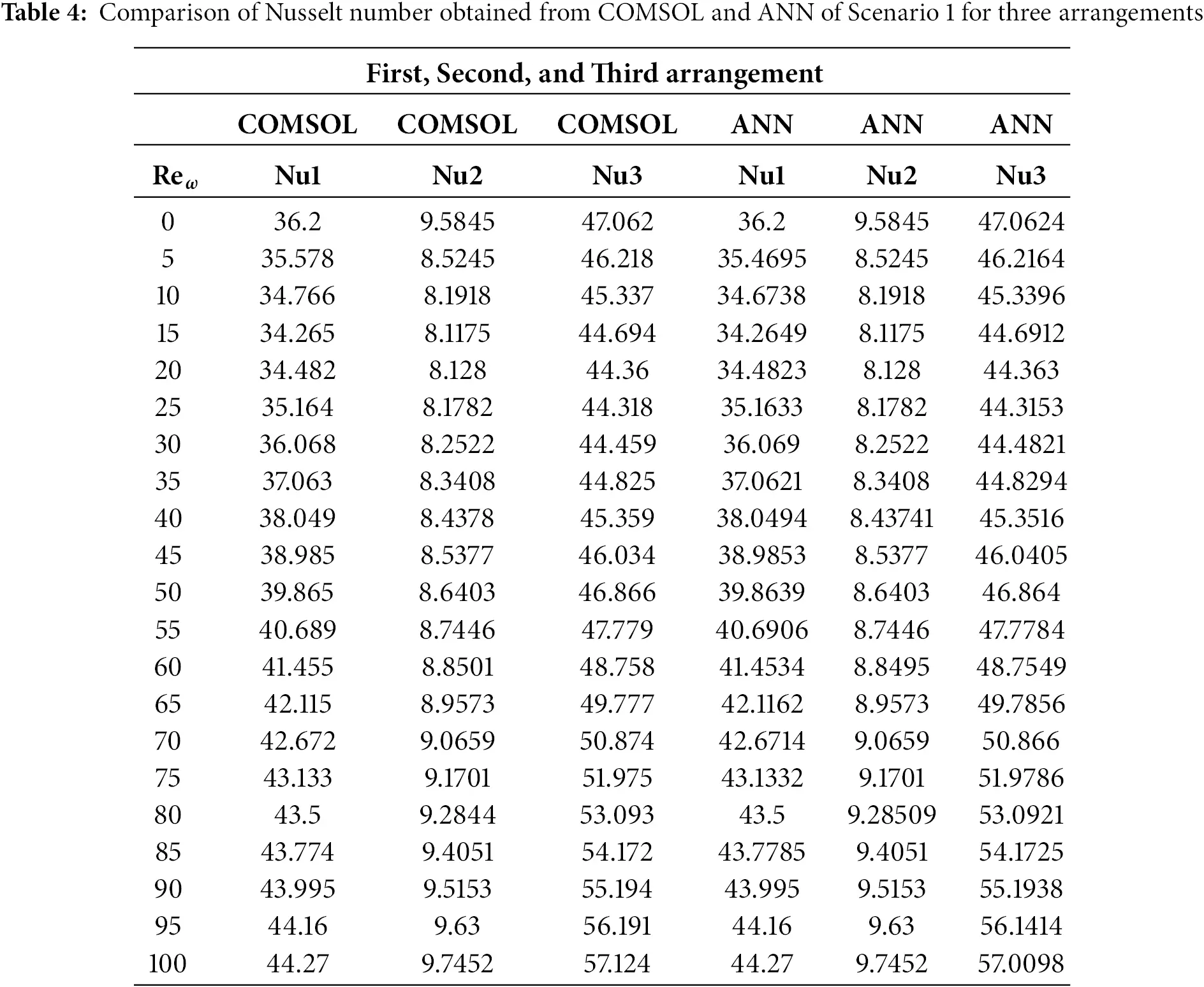

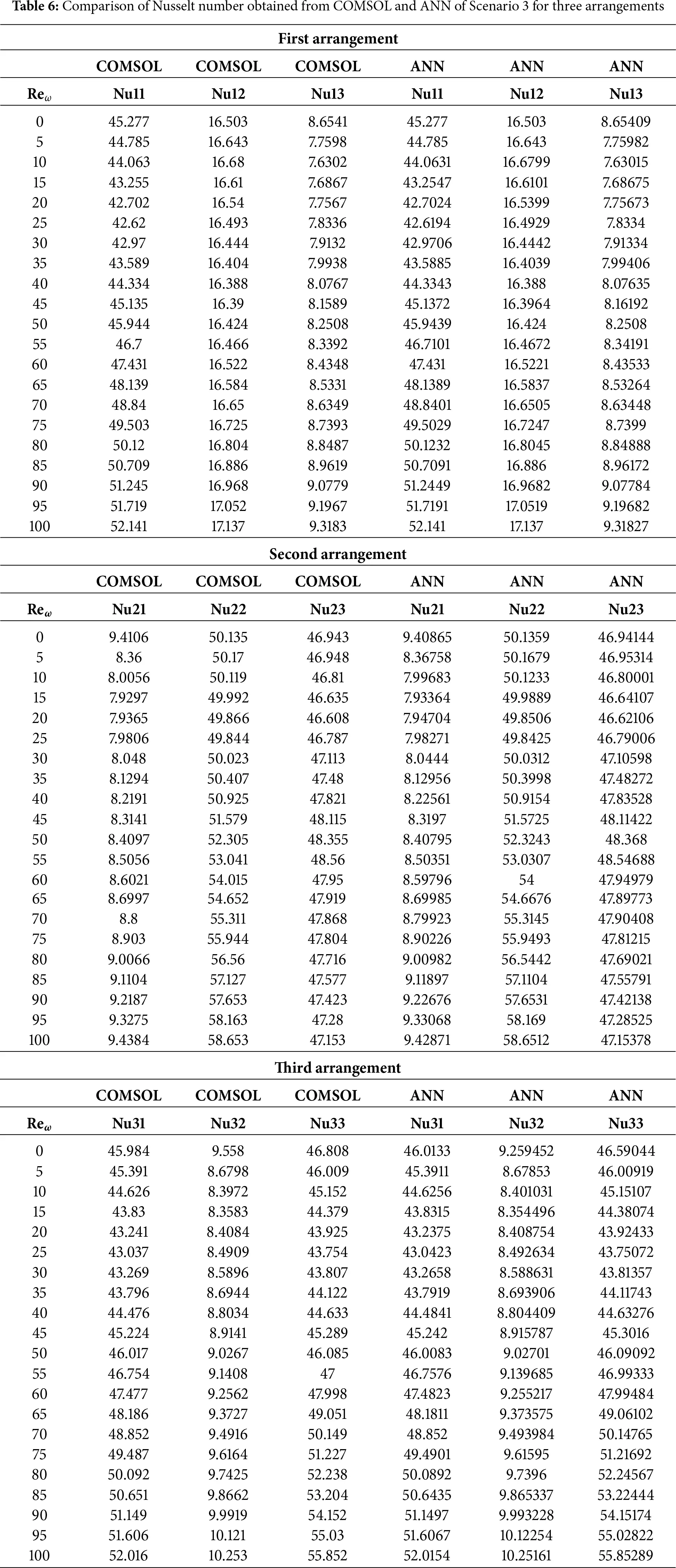
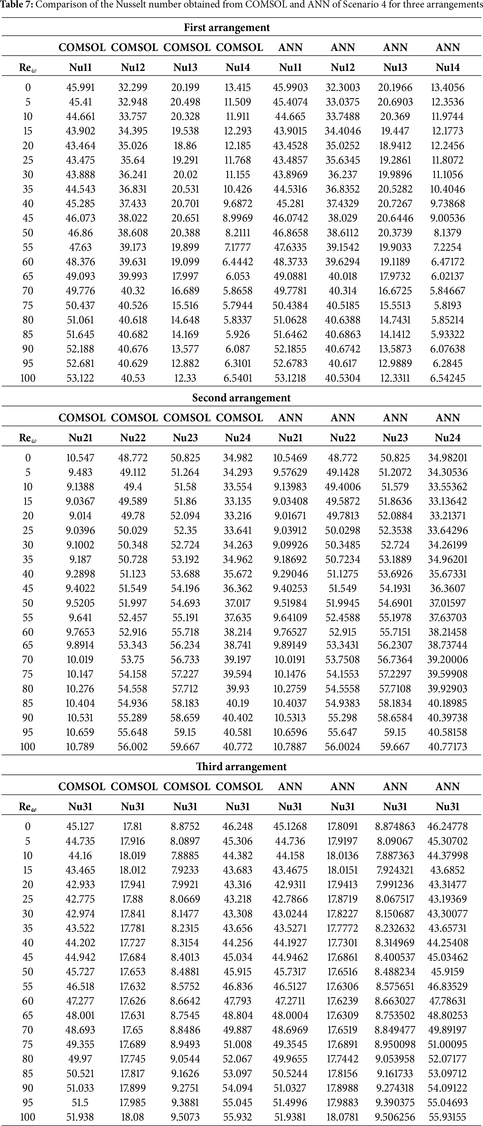

In Table 6, Scenario 3 analyzes three-cylinder systems with arrangements Nu11 to Nu13 (first), Nu21 to Nu23 (second), and Nu31 to Nu33 (third). A consistent upward trend in Nusselt number with Reω is observed in all arrangements. Interestingly, the third cylinder in each case (Nu13, Nu23, Nu33) tends to exhibit the highest thermal performance, highlighting the advantage of edge or downstream cylinder placements. ANN predictions align almost perfectly with COMSOL outputs, further affirming the reliability of the surrogate model in replicating complex thermal behavior. Table 7 explores Scenario 4 with four rotating cylinders, comparing Nusselt numbers Nu11 to Nu14 across three arrangements. As rotational speed increases, the Nusselt numbers improve, especially for the outer cylinders (Nu11, Nu12), which benefit from enhanced flow interaction. Some cylinders show a peak followed by a slight decline at higher Reω, indicating the onset of thermal saturation or shielding effects. Again, the ANN model mirrors the COMSOL results with high accuracy, indicating its suitability for capturing subtle variations across multi-cylinder configurations. Finally, Table 8 addresses Scenario 5, involving five rotating cylinders and five local Nusselt number outputs (Nu11 to Nu15). As Reω increases, a rise in heat transfer is observed, particularly for outer or strategically placed cylinders such as Nu14 and Nu15. The second arrangement reveals more complex trends, including non-linear behavior and localized saturation due to denser cylinder spacing. The third arrangement shows homogenization of thermal response at high Reω, due to enhanced convective interactions among all five cylinders. The ANN predictions remain accurate and consistent throughout, despite the increased complexity. Overall, the results across all five scenarios confirm that rotational motion significantly enhances heat transfer and that cylinder placement plays a critical role in determining local thermal performance. The ANN model demonstrates to be a powerful predictive tool, providing computational efficiency without sacrificing accuracy. These findings highlight the potential of combining machine learning with numerical simulation for optimizing heat transfer systems in complex geometries.
Numerical Validation and Grid Independence Test
The finite element mesh was systematically constructed, discretized, and refined to ensure accuracy and grid independence of the numerical results. Initially, different mesh levels were generated, ranging from extremely coarse to finer. For each refinement level, the number of vertices and elements increased, which led to improved resolution of the flow and thermal fields. The statistics of mesh quality were monitored to confirm that the elements maintained good aspect ratios and acceptable skewness values.
The average Nusselt number (Nu) was computed at various mesh levels for representative cylinders (C1, C2, and C3) under two different Reynolds numbers (Reω=0 and 100) to validate grid independence. Table 9 shows that beyond the finer mesh level, further refinement produced only minor changes in the Nusselt number. This indicates that the solution is no longer sensitive to mesh density, and the grid is sufficiently fine to capture the physics of the problem. Thus, the finer mesh was chosen as the optimal compromise between computational cost and accuracy for all subsequent simulations. This ensures that the reported results are mesh-independent and reliable. This grid-independence test demonstrates that the present results are numerically stable and convergent, and therefore reliable.
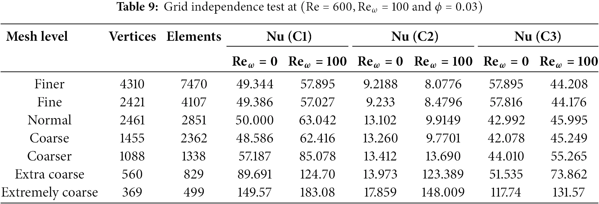
For model validation, Table 10 compares the predicted Nusselt numbers over a range of rotational Reynolds numbers with benchmark data from [33]. The close agreement substantiates the robustness and credibility of the present numerical model.
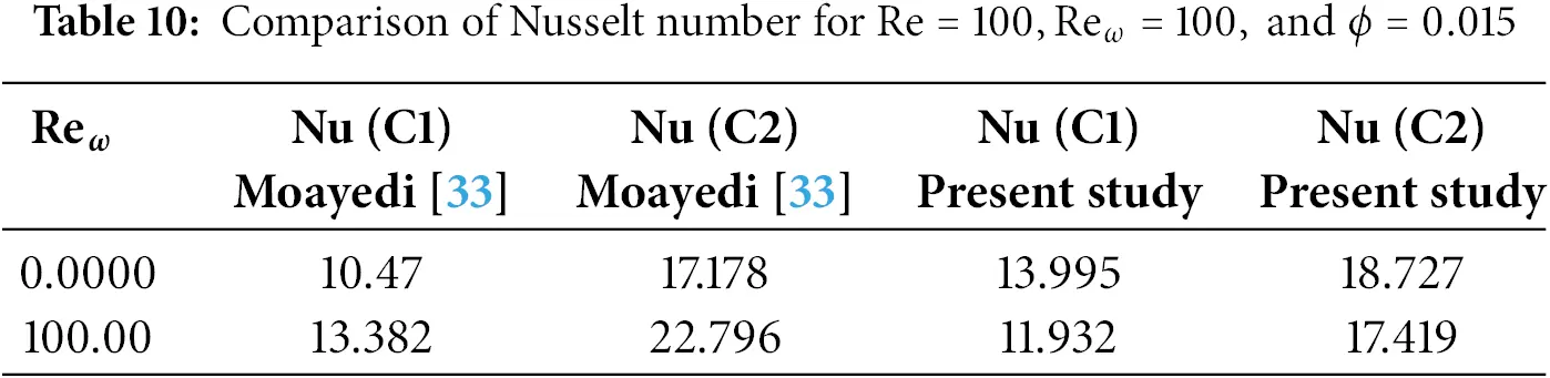
4 Conclusion
The study successfully examines how the flow field, heat transfer, and streamlining behaviors are affected by the cylinder positioning and rotating Reynolds number. In every instance, compared to the stationary situation Reω=0, increasing rotational speed (Reω=100) results in stronger vortical structures, improved fluid mixing, and thermal convection. Wake interaction, vortex formation, and heat distribution symmetry are significantly impacted by the configuration and quantity of cylinders. As evidenced by low error rates and robust regression fits, ANNs trained with Bayesian Regularization show good accuracy and generalization in forecasting fluid dynamic responses. The viability of employing ANN for effective modeling of complex flow systems with several rotating barriers is confirmed by this combined numerical-machine learning technique. The Key findings of this study, for all the cases, are listed below.
Scenario 1:
❖ The streamline patterns under Reω=0 and Reω=100 for all three-cylinder placements show unique and vortex behaviors, indicating that the recirculation zones are very sensitive to Reynolds wall effects and geometry.
❖ Temperature contours demonstrate significant variation between placements and Reω values; increased convective transport at Reω=100 results in enhanced thermal gradients and distortion around the cylinders.
❖ Velocity contours illustrate greater velocity zones and shear layers downstream of the cylinders, with Reω=100 fostering more intense and directed flow structures compared to the stagnant patterns at Reω=0.
❖ The ability of the ANN in capturing the flow and heat transfer behavior of nanofluids around cylinders is validated by the training and validation plots, which consistently show excellent predicted accuracy and minimum error across arrangements.
Scenario 2:
❖ In the second scenario, changes in cylinder location clearly alter flow symmetry and vortex structures; in all three configurations, rotation (Reω=100) produces large asymmetries and improved vortex dynamics.
❖ Centrifugal moving and geometry-driven flow changes cause thermal fields to change from symmetric conduction-dominated layers (Reω=0) to highly skewed and convectively mixed profiles (Reω=100).
❖ Velocity contours highlight the combined role of dispersion and rotation by showing the change from laminar, geometry-induced recirculation zones (Reω=0) to active rotational mixing and higher shear zones (Reω=100).
❖ Bayesian Regularization-based ANN models demonstrate strong predictive ability across geometric changes with high regression accuracy (R≈1), minimal error distribution, and outstanding training performance in all three configurations of the second case.
Scenario 3
❖ Increasing the number of cylinders and adding rotation (Reω=100) to all three configurations causes complex separation of streams and dynamic recirculation zones by intensifying vortex shedding and upsetting symmetry.
❖ By stretching and deforming isotherms, cylinder rotation improves convective heat transfer, particularly in asymmetric configurations where thermal boundary layers thin unevenly.
❖ The velocity contours show that while non-rotating cases exhibit low momentum zones because of geometric obstruction and energy loss in wakes, rotation significantly increases and localized acceleration.
❖ Regularization by Bayesian, high accuracy, low error distribution, and good generalization are consistently displayed by ANN models, which successfully capture the nonlinear fluid-thermal behavior in all configurations.
Scenario 4:
❖ Rotation (Reω=100) increases vortex displacement and stream changes in all cases, but various cylinder configurations significantly alter vortex patterns and flow symmetry.
❖ Rotational motion facilitates heat transport, elongates isotherms, and encourages thermal mixing, whereas static configurations lead to symmetric stacking and thermal accumulation.
❖ In rotating cases, velocity contours reveal enhanced flow and flow channeling, while stagnation zones and decreased flow efficiency are the result of static conditions.
❖ Based on Bayesian Regularization with low training error, centered error histograms, and regression graphs showing excellent accuracy and generalization, ANN demonstrates outstanding predictive ability.
Scenario 5:
❖ Strong rotational forces and Magnus-induced circulations cause the streamline patterns to change from symmetric vortex structures at Reω=0 to intensive swirling and vortex shedding at Reω=100 for all cylinder positions.
❖ Under Reω=100, isothermal contours emphasize increased convective heat transfer because of vortex-driven mixing, moving from localized thermal concentrations at Reω=0 to more stretched and scattered patterns.
❖ Although cylinder rotation (Reω=100) injects momentum, producing high-speed inter-cylinder jets and more consistent downstream acceleration, velocity fields display low-speed wakes and blocked zones for non-rotating situations.
❖ Strong predictive skills across all five-cylinder configurations are confirmed by the ANN models trained with Bayesian Regularization, which consistently exhibit minimal training errors, symmetric error histograms, and high regression accuracy.
The ANN model accurately predicts Nusselt numbers across all scenarios, closely matching COMSOL results with negligible error.
Heat transfer improves significantly with increasing rotational Reynolds number and optimized cylinder placement.
Arrangement 3 in Scenario 3 consistently shows the highest Nusselt number values, particularly Nu33, indicating superior heat transfer performance due to optimal cylinder placement and strong vortex formation.
Similarly, in Scenario 5, Arrangement 1 exhibits higher values in Nu11 and Nu14, indicating it performs better thermally compared to the second and third arrangements.
This study provides valuable insights into nanofluid heat transfer enhancement in a Γ-shaped enclosure with rotating cylinders. Several limitations should be acknowledged:
❖ Geometry Simplification: The 2D cavity with uniform cylinders omits 3D and irregular effects found in real heat exchangers and rotating machinery.
❖ Constant Properties: Cu water nanofluid properties were treated as constant, unlike in turbine cooling or microchannel flows, where temperature alters viscosity and conductivity.
❖ Neglected Effects: Radiation, viscous dissipation, and buoyancy were ignored, though they are important in solar collectors, nuclear cooling, and high-speed devices.
❖ Limited Parameters: Only laminar flow, fixed Reω, and one nanoparticle type were tested, while practical systems face turbulence, variable speeds, and hybrid nanofluids.
❖ ANN Scope: The ANN is trained solely on FEM data and not validated for other geometries or fluids used in mixers, bearings, or seals.
❖ No Experiments: The study lacks experimental validation, which is essential for applications in electronics cooling, automotive, and aerospace thermal systems.
Acknowledgement: This work was supported and funded by the Deanship of Scientific Research at Imam Mohammad Ibn Saud Islamic University (IMSIU) (grant number IMSIU-DDRSP2503).
Funding Statement: This work was supported and funded by the Deanship of Scientific Research at Imam Mohammad Ibn Saud Islamic University (IMSIU) (grant number IMSIU-DDRSP2503).
Author Contributions: Conceptualization, Adnan Ashique, Maddina Dinesh Kumar and Nehad Ali Shah; Methodology, Usman Afzal, Mati Ur Rahman and Sohaib Abdal; Software, Adnan Ashique and Maddina Dinesh Kumar; Validation, Nehad Ali Shah and Sohaib Abdal; Formal analysis, Usman Afzal, Mati Ur Rahman and Nehad Ali Shah; Resources, Adnan Ashique and Maddina Dinesh Kumar; Writing—original draft, Adnan Ashique and Usman Afzal; Writing—review & editing, Nehad Ali Shah, Maddina Dinesh Kumar, Mati Ur Rahman and Sohaib Abdal. All authors have read and agreed to the published version of the manuscript. Adnan Ashique and Nehad Ali Shah contributed equally to this work and are co-first authors. All authors reviewed the results and approved the final version of the manuscript.
Availability of Data and Materials: The data that support the findings of this study are available from the corresponding author upon reasonable request.
Ethics Approval: Not applicable.
Conflicts of Interest: The authors declare no conflicts of interest to report regarding the present study.
Nomenclature

References
1. Ali NB, Mahmood Z, Bani-Fwaz MZ, Khan SU, Tlili I. Thermal efficiency of radiated nanofluid through convective geometry subject to heating source. Ain Shams Eng J. 2024;15(10):102947. doi:10.1016/j.asej.2024.102947. [Google Scholar] [CrossRef]
2. Atofarati EO, Sharifpur M, Huan Z. Nanofluids for heat transfer enhancement: a holistic analysis of research advances, technological progress and regulations for health and safety. Cogent Eng. 2024;11(1):2434623. doi:10.1080/23311916.2024.2434623. [Google Scholar] [CrossRef]
3. Ullah Z, El-Zahar ER, Seddek LF, Becheikh N, Alshammari BM, Aldhabani MS, et al. Solar radiation and heat sink impact on fluctuating mixed convective flow and heat rate of Darcian nanofluid: applications in electronic cooling systems. Case Stud Therm Eng. 2024;59:104592. doi:10.1016/j.csite.2024.104592. [Google Scholar] [CrossRef]
4. Tshivhi KS, Tshehla MS. Heat source and radiation effects on MHD flow of Copper-Water nanofluid over exponential stretching surface with slip. Results Phys. 2024;58:107463. doi:10.1016/j.rinp.2024.107463. [Google Scholar] [CrossRef]
5. Nicholaus Lutera J, Shekar MR, Goud BS. Numerical method of radiation impact on unsteady MHD nanofluid flow past an accelerated vertical porous plate with heat source. Int J Model Simul. 2024;57(3):1–9. doi:10.1080/02286203.2024.2318831. [Google Scholar] [CrossRef]
6. Ramasekhar G, Jawad M, Divya A, Jakeer S, Ghazwani HA, Almutiri MR, et al. Heat transfer exploration for bioconvected tangent hyperbolic nanofluid flow with activation energy and joule heating induced by Riga plate. Case Stud Therm Eng. 2024;55(10):104100. doi:10.1016/j.csite.2024.104100. [Google Scholar] [CrossRef]
7. Venkateswarlu B, Satya Narayana PV, Chamkha AJ. Heat energy impacts on hybrid (copper-titanium/water) nanofluid flow over a porous elongated sheet. J Nanofluids. 2024;13(4):863–72. doi:10.1166/jon.2024.2181. [Google Scholar] [CrossRef]
8. Madhuri NJP, Shamshuddin MD, Salawu SO. Exploring radiative heat transfer and buoyancy effects on Tiwari-Das nanofluid flow model in permeable rotating disc: finite element study. Therm Sci Eng Prog. 2025;65:103855. doi:10.1016/j.tsep.2025.103855. [Google Scholar] [CrossRef]
9. Parasuraman L, Begum AM. The impact of suction/injection with radiation effect on natural convection flow over a vertical channel in the existence of point/line heat source configuration. Int J Comput Methods Eng Sci Mech. 2025;26(2):98–109. doi:10.1080/15502287.2024.2394889. [Google Scholar] [CrossRef]
10. Mateus R, Pinto A, Pereira JM. CFD methodology for predicting thermal plume from heat source: experimental validation and simplified model. Build Environ. 2024;257:111526. doi:10.1016/j.buildenv.2024.111526. [Google Scholar] [CrossRef]
11. Kandeal AW, Ismail M, Basem A, Elsayad MM, Alawee WH, Majdi HS, et al. An overview of the improvement of natural convection heat transfer via surface thermal radiation for different geometries. Res Eng. 2024;23:102514. doi:10.1016/j.rineng.2024.102514. [Google Scholar] [CrossRef]
12. Khan MS, Ahmad S, Shah Z, Vrinceanu N, Alshehri MH. Natural convection heat transfer of a hybrid nanofluid in a permeable quadrantal enclosure with heat generation. Case Stud Therm Eng. 2024;56(1):104207. doi:10.1016/j.csite.2024.104207. [Google Scholar] [CrossRef]
13. Shanthi M, Hemamalini PT, Asmat F, Abdullaeva S, Waqas M, Gupta M, et al. Free convective and radiating flow confined between vertical parallel MHD plates with heat transfer and uniform inclined magnetic field. Int J Thermofluids. 2024;23(1):100765. doi:10.1016/j.ijft.2024.100765. [Google Scholar] [CrossRef]
14. Anwar MS, Alqarni MS, Irfan M. Exploring the marvels of heat transfer: mHD convection at a stagnation point in non-Newtonian fluid with yield stress and chemical reactions. Chin J Phys. 2024;89:1299–308. doi:10.1016/j.cjph.2024.01.030. [Google Scholar] [CrossRef]
15. Uysal C. Which parameter should be used in evaluating nanofluid flows: Reynolds number, velocity, mass flow rate or pumping power? Heat Transf Res. 2020;51(5):447–97. doi:10.1615/heattransres.2019030372. [Google Scholar] [CrossRef]
16. Basavaraj K, Elangovan K, Shankar S, Kulkarni A. Effects of reynolds number on the volume concentration of Al2O3 in ethylene glycol. Int J Veh Struct Syst (IJVSS). 2023;15(3):13. [Google Scholar]
17. Gupta S, Subbarao PMV. Empirical investigation of nanofluid performance in a microchannel heat sink for various attributes in low Reynolds number range. Int J Heat Fluid Flow. 2024;105(10):109258. doi:10.1016/j.ijheatfluidflow.2023.109258. [Google Scholar] [CrossRef]
18. Saldana M, Gallegos S, Gálvez E, Castillo J, Salinas-Rodríguez E, Cerecedo-Sáenz E, et al. The reynolds number: a journey from its origin to modern applications. Fluids. 2024;9(12):299. doi:10.3390/fluids9120299. [Google Scholar] [CrossRef]
19. Wang H, Jia Y, Kong D, Zhao G, Liu C. A numerical study on vane heat transfer characteristic at low Reynolds number conditions. Appl Therm Eng. 2024;245:122819. doi:10.1016/j.applthermaleng.2024.122819. [Google Scholar] [CrossRef]
20. Ozalp C, Saydam DB, Polat C, Soyler M, Hürdoğan E. An experimental investigation of the flow characteristics and heat transfer properties of a heated and an unheated vertically positioned circular cylinder at different Reynolds numbers. Int J Heat Mass Transf. 2023;201:123637. doi:10.1016/j.ijheatmasstransfer.2022.123637. [Google Scholar] [CrossRef]
21. Nguyen TNQ, Kuo HH, Liao CC, Lin K. 3-D CFD analysis of convective heat transfer from a heated horizontal cylinder rotating in air: from laminar to turbulent flow. ASME J Heat Mass Transfer. 2025;147(7):071801. doi:10.1115/1.4068377. [Google Scholar] [CrossRef]
22. Singh RJ, Kannan YS, Yadav HK, Rahul. Numerical study on the influence of solutal buoyancy on mixed convection heat and mass transfer in skewed domain. Heat Transfer Eng. 2025. doi:10.1080/01457632.2025.2452747. [Google Scholar] [CrossRef]
23. Xu T, Choi JI. Numerical investigation of flow and heat transfer characteristics in buoyancy-driven convection around cylinder arrays within an enclosure. Phys Fluids. 2025;37(2):023610. doi:10.1063/5.0251568. [Google Scholar] [CrossRef]
24. Kannan V, Zhu X. Transition between rotation-and buoyancy-dominated regimes in rotating convection: the effect of boundary conditions. J Fluid Mech. 2025;1011:A7. doi:10.1017/jfm.2025.379. [Google Scholar] [CrossRef]
25. Ishaq M, Ashraf MB, Ashraf MU, Alshehery S, Faqihi AA, Hadidi HM. Artificial neural network-based study of entropy optimization in Johnson-Segalman nanofluids through a peristaltic channel. Phys Fluids. 2025;37(3):033103. doi:10.1063/5.0255518. [Google Scholar] [CrossRef]
26. Alsemiry RD, Ahmed SE, Eid MR, Elsaid EM. ANN-based prediction and RSM optimization of radiative heat transfer in couple stress nanofluids with thermodiffusion effects. Processes. 2025;13(4):1055. doi:10.3390/pr13041055. [Google Scholar] [CrossRef]
27. Rehman KU, Fatima N, Shatanawi W, Kousar N. Mathematical solutions for coupled nonlinear equations based on bioconvection in MHD Casson nanofluid flow. AIMS Math. 2025;10(1):598–633. doi:10.3934/math.2025027. [Google Scholar] [CrossRef]
28. Bilal M, Maiz F, Farooq M, Ahmad H, Nasrat MK, Ghazwani HA. Novel numerical and artificial neural computing with experimental validation towards unsteady micropolar nanofluid flow across a Riga plate. Sci Rep. 2025;15(1):759. doi:10.1038/s41598-024-84480-3. [Google Scholar] [PubMed] [CrossRef]
29. Zeeshan A, Yousif MA, Imran Khan M, Latif MA, Ali SS, Mohammed PO. Non-similar analysis of boundary layer flow and heat transfer in non-Newtonian hybrid nanofluid over a cylinder with viscous dissipation effects. Energies. 2025;18(7):1660. doi:10.3390/en18071660. [Google Scholar] [CrossRef]
30. Dhar JP, Hasan M, Nishiyama E, Toyoda I. Microstrip patch antenna design using a four-layer feed forward artificial neural network trained by levenberg-marquardt algorithm. IEEE Access. 2025;13:55244–57. doi:10.1109/access.2025.3553913. [Google Scholar] [CrossRef]
31. Hussain S, Jayavel P, Almutairi B, Ramesh K. Enhanced heat transfer analysis of micropolar hybrid-nanofluids in an incinerator-shaped cavity. Therm Sci Eng Prog. 2025;60(6):103471. doi:10.1016/j.tsep.2025.103471. [Google Scholar] [CrossRef]
32. Hussain S, Jayavel P, Almutairi B, Ramesh K. MHD and radiative convection in a fin-assisted NEPCM-filled enclosure under thermal and particle concentration gradients: implications for energy storage and cooling. J Energy Storage. 2025;133:117977. doi:10.1016/j.est.2025.117977. [Google Scholar] [CrossRef]
33. Moayedi H. Investigation of heat transfer enhancement of Cu-water nanofluid by different configurations of double rotating cylinders in a vented cavity with different inlet and outlet ports. Int Commun Heat Mass Transf. 2021;126:105432. doi:10.1016/j.icheatmasstransfer.2021.105432. [Google Scholar] [CrossRef]
34. Jasim LM, Hamzah H, Canpolat C, Sahin B. Mixed convection flow of hybrid nanofluid through a vented enclosure with an inner rotating cylinder. Int Commun Heat Mass Transf. 2021;121:105086. doi:10.1016/j.icheatmasstransfer.2020.105086. [Google Scholar] [CrossRef]
35. Jafaripournimchahi A, Shateri A, Jalili B, Jalili P, Ganji DD. The effects of magnetic field and thermal radiation on the mixed convection of Al2O3-Cu/water hybrid nanofluid over a permeable vertical flat plate. Mod Phys Lett B. 2024;38(25):2450242. doi:10.1142/s0217984924502427. [Google Scholar] [CrossRef]
36. Raja Rajeswari V, Venkatadri K, Ramachandra Prasad V. Nanoparticle shape factor impact on double diffusive convection of Cu-water nanofluid in trapezoidal porous enclosures: a numerical study. Num Heat Trans Part A Appl. 2024;1–20. [Google Scholar]
37. Manaa N, Abidi A, Hussein AK, Alliche M, Borjini MN, Kolsi L. Numerical study of thermo-solutal convection of a Cu/water micropolar nanofluid in a cubic cavity saturated with porous media. Eur Phys J Spec Top. 2024;233(13):2245–63. doi:10.1140/epjs/s11734-024-01111-8. [Google Scholar] [CrossRef]
38. Sayyou H, Belabid J, Öztop HF, Allali K. Vibrational effects on thermosolutal free convection of Cu-Al2O3/water nanofluids in a partially heated and salted square porous enclosure. J Mol Liq. 2025;423:126990. doi:10.1016/j.molliq.2025.126990. [Google Scholar] [CrossRef]
39. Rashad AM, Abdulrazzaq T, Kolsi L, Mansour MA, Aoudia M, Salah T, et al. Entropy generation due to MHD natural convection in a square enclosure with heater corners saturated porous medium using Cu/water nanofluid containing insulated obstacle. J Braz Soc Mech Sci Eng. 2025;47(8):373. doi:10.1007/s40430-025-05672-0. [Google Scholar] [CrossRef]
40. Al-Kouz W, Abderrahmane A, Shamshuddin MD, Younis O, Mohammed S, Bég OA, et al. Heat transfer and entropy generation analysis of water-Fe3O4/CNT hybrid magnetic nanofluid flow in a trapezoidal wavy enclosure containing porous media with the Galerkin finite element method. Eur Phys J Plus. 2021;136(11):1–23. doi:10.1140/epjp/s13360-021-02192-3. [Google Scholar] [CrossRef]

 Submit a Paper
 Propose a Special lssue
 Open Access
 View Full Text
 Download PDF

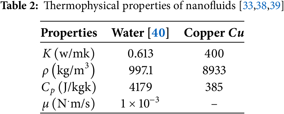
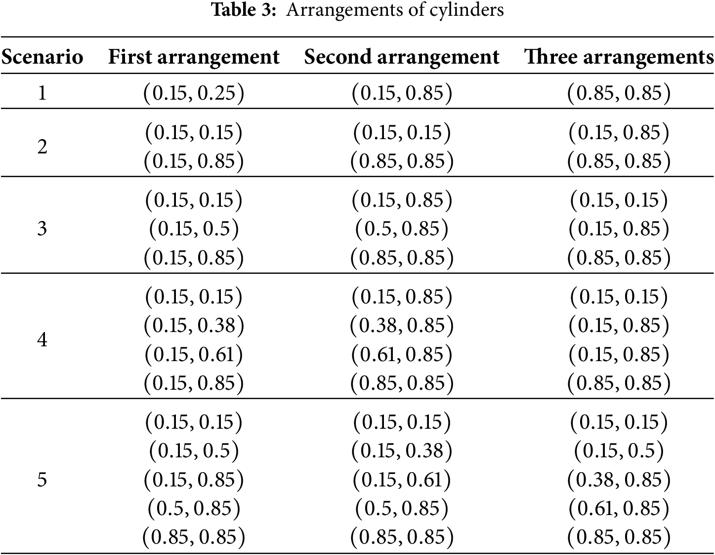

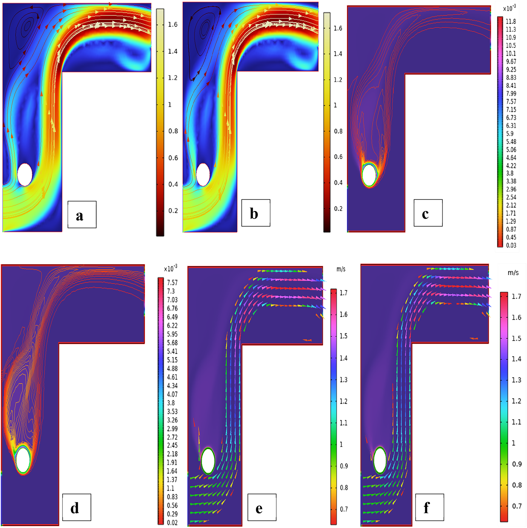
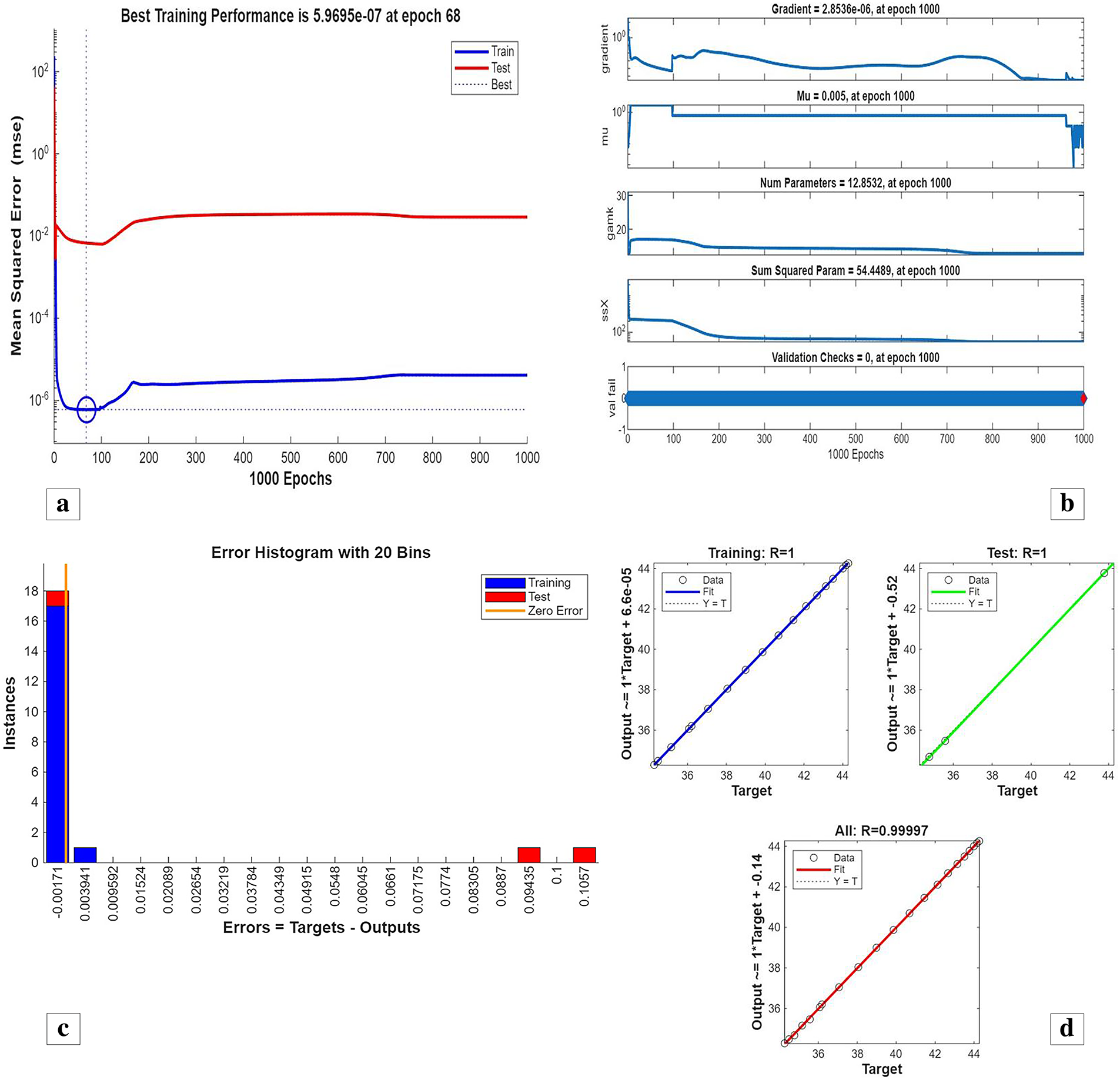


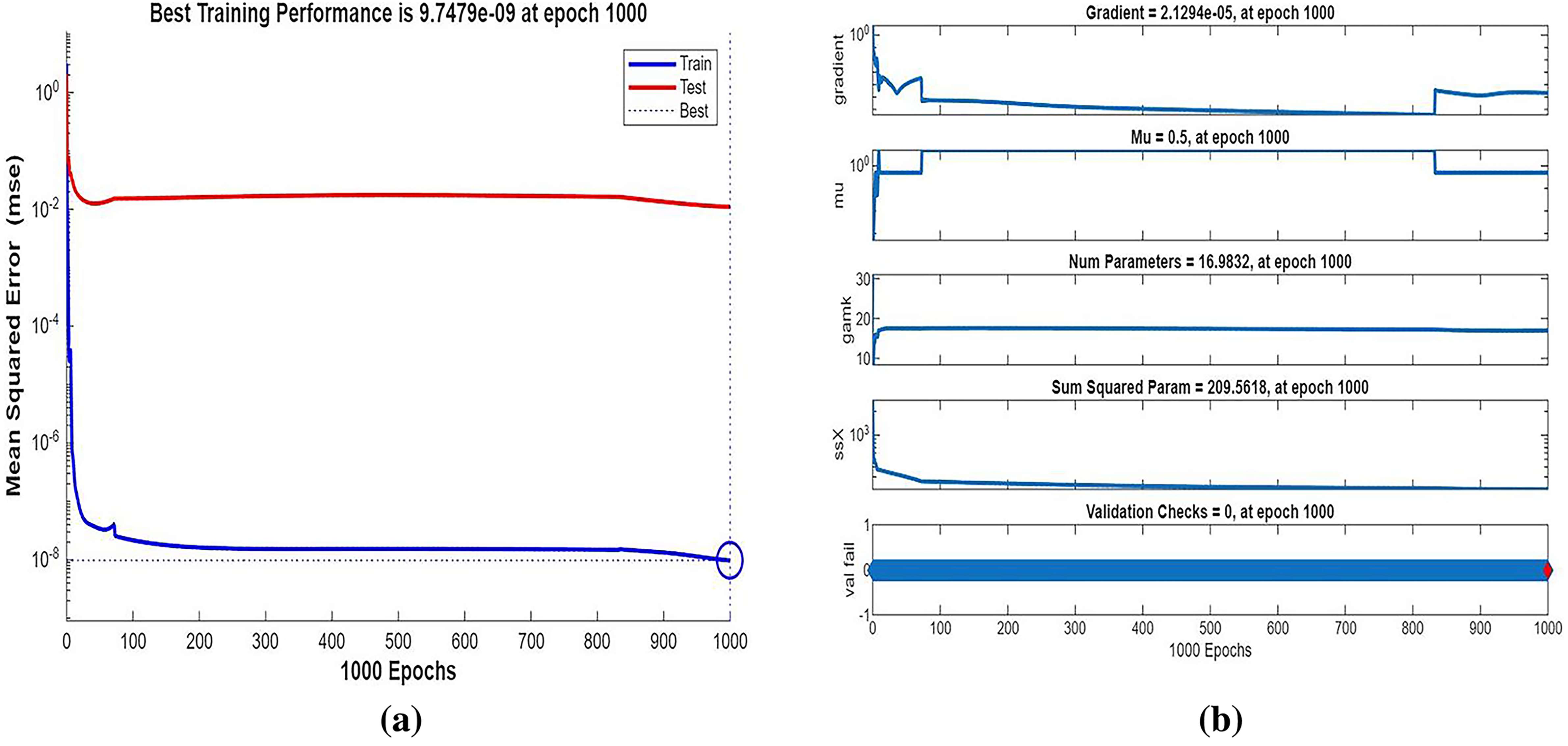
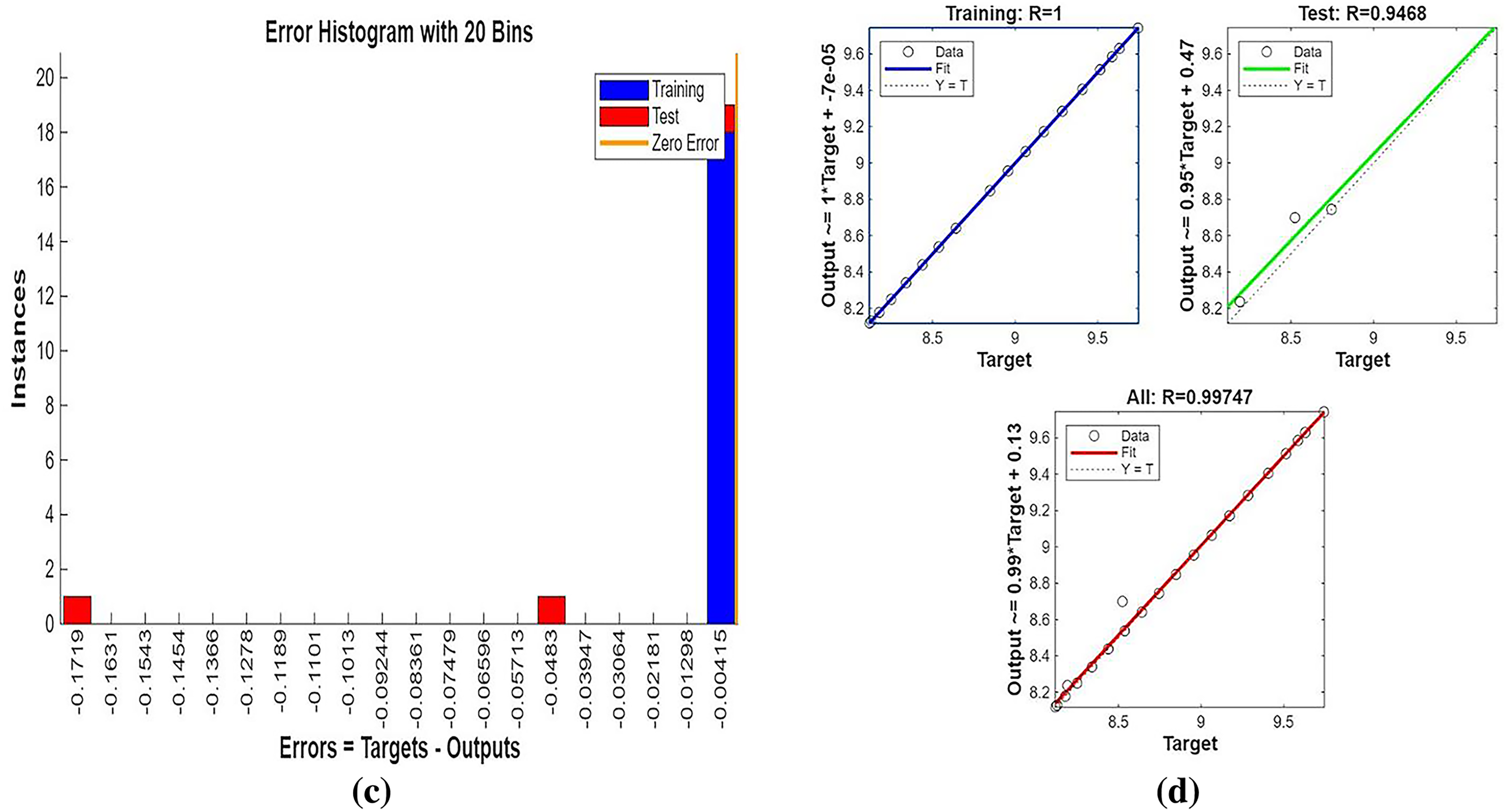


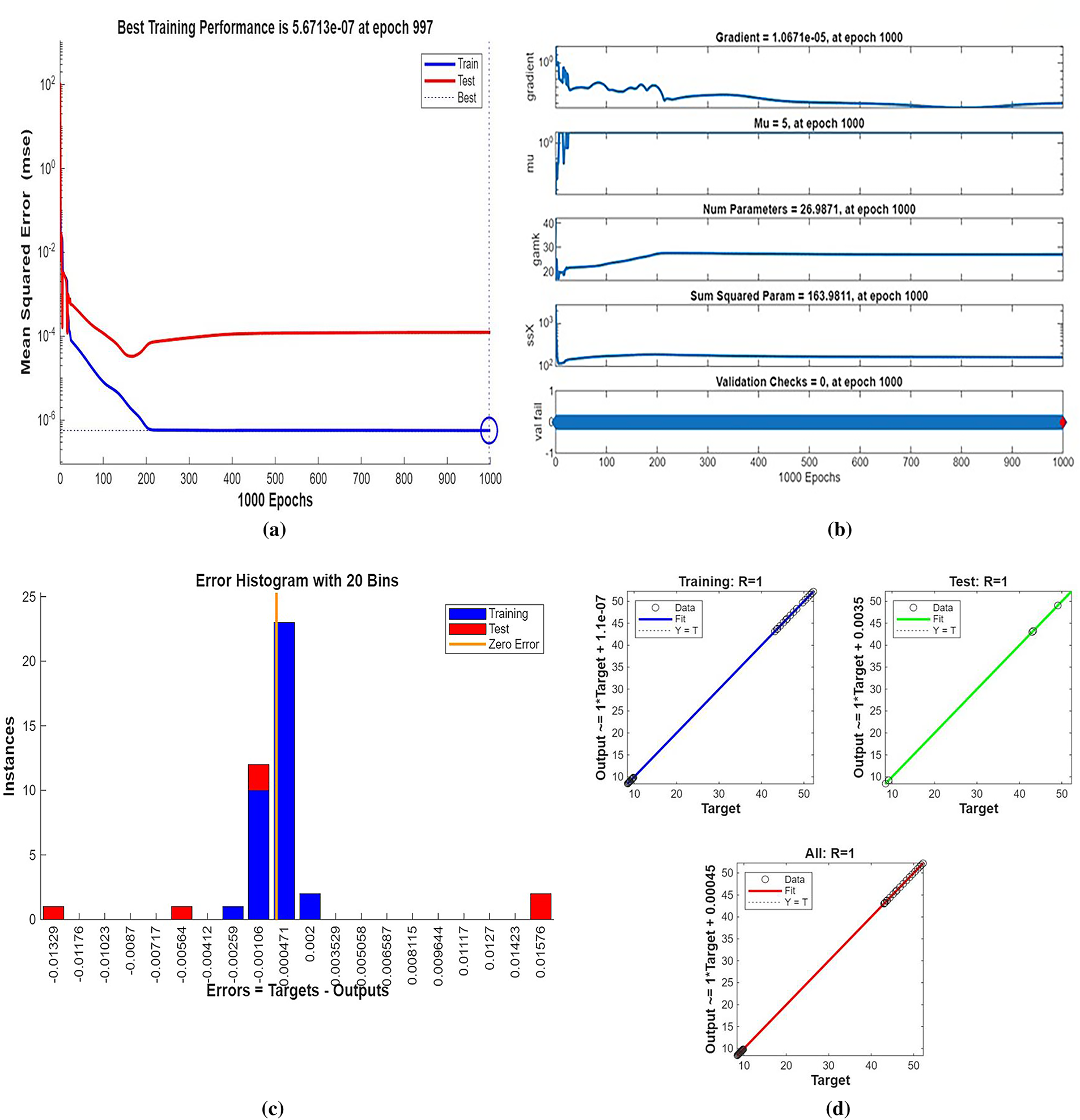

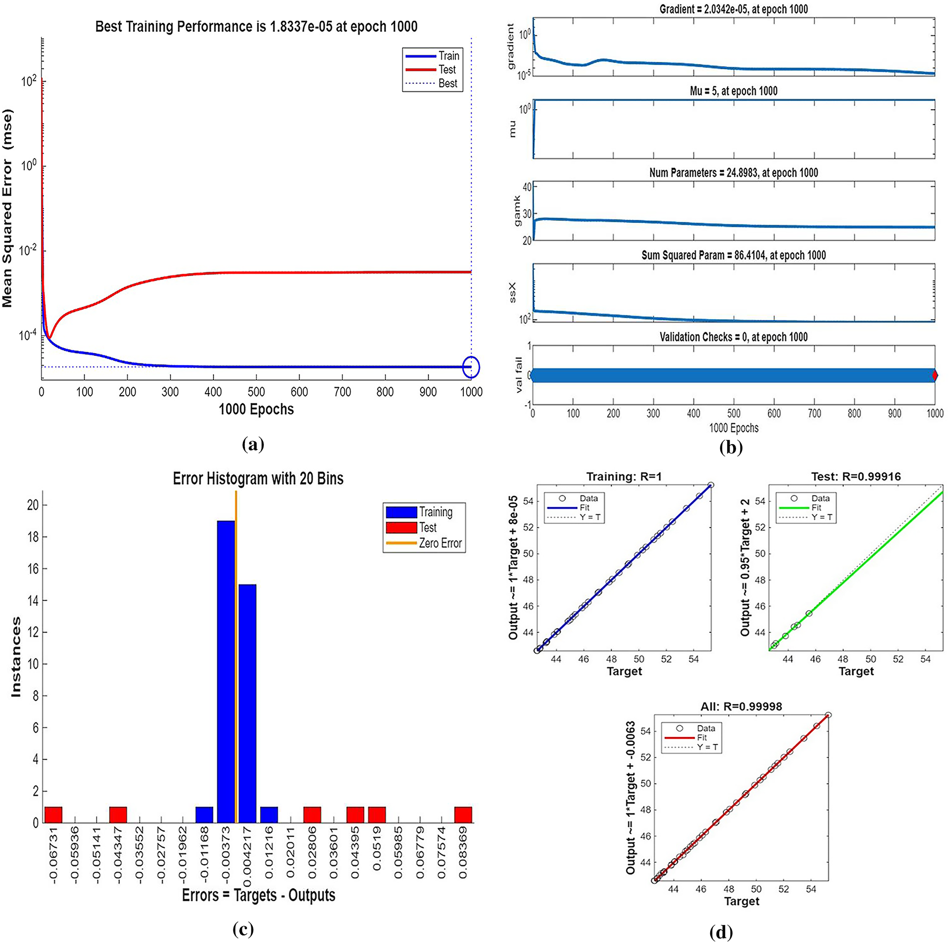
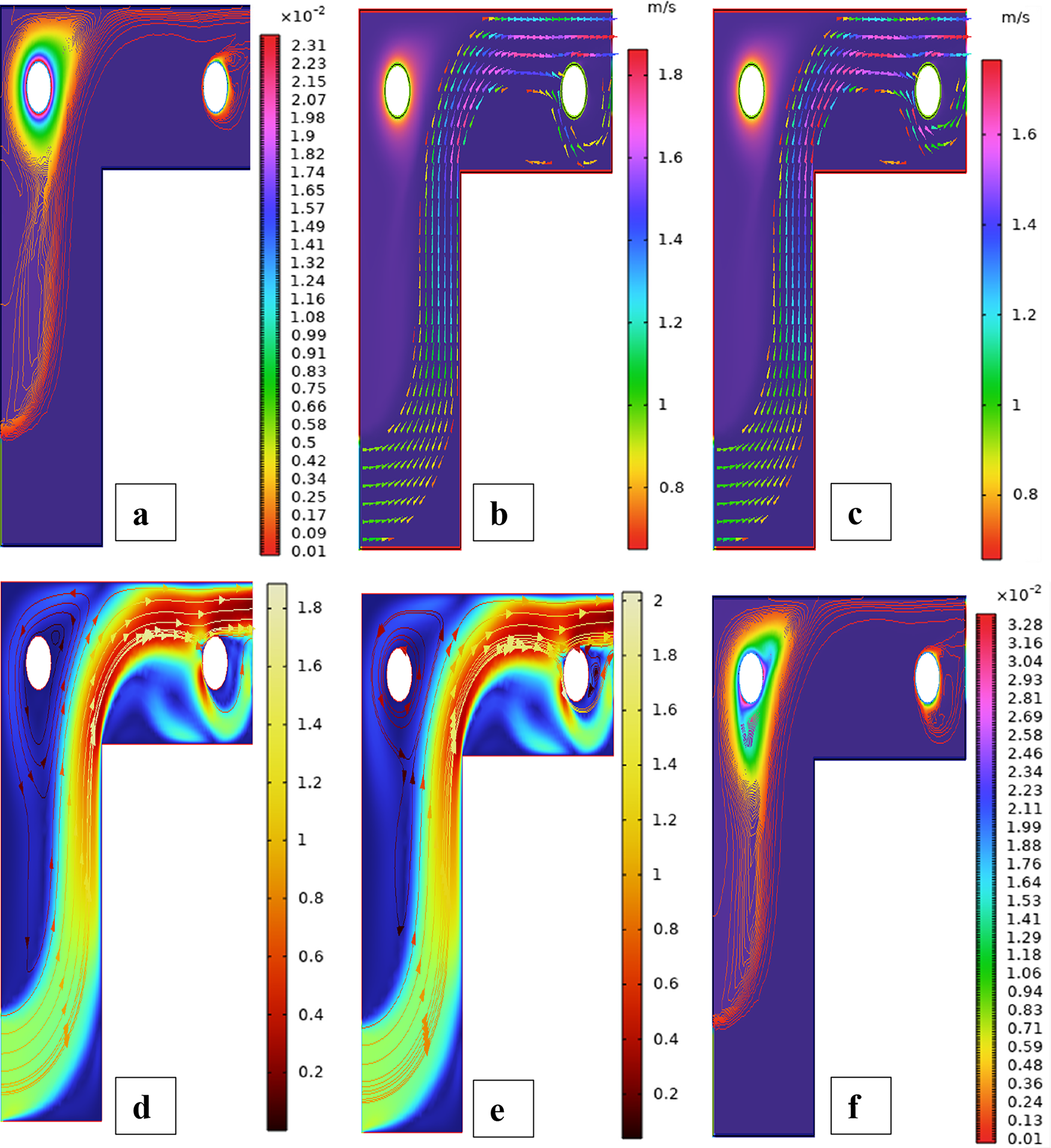
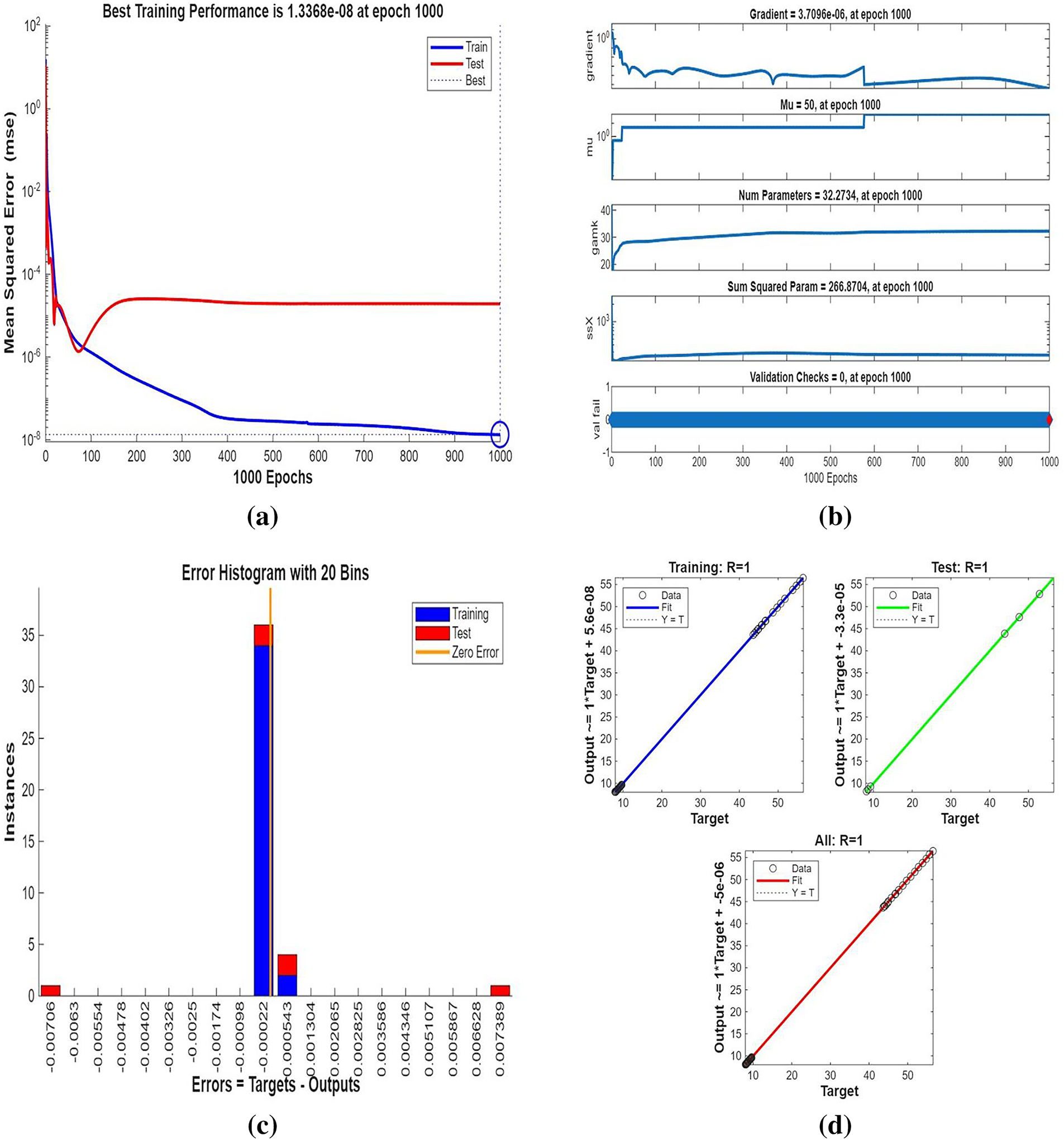
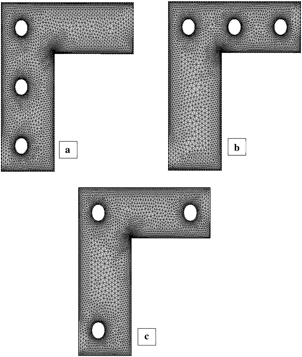
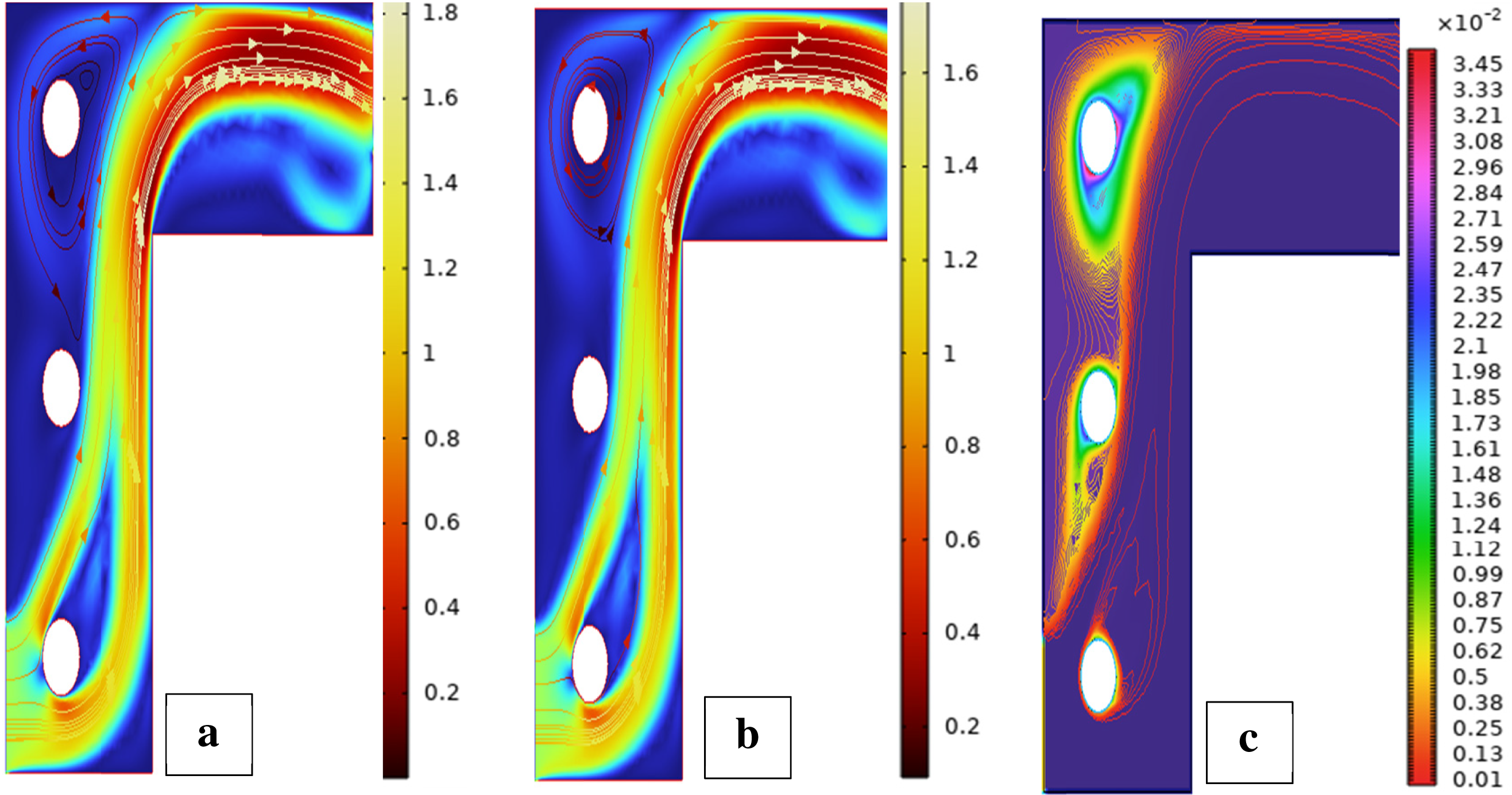
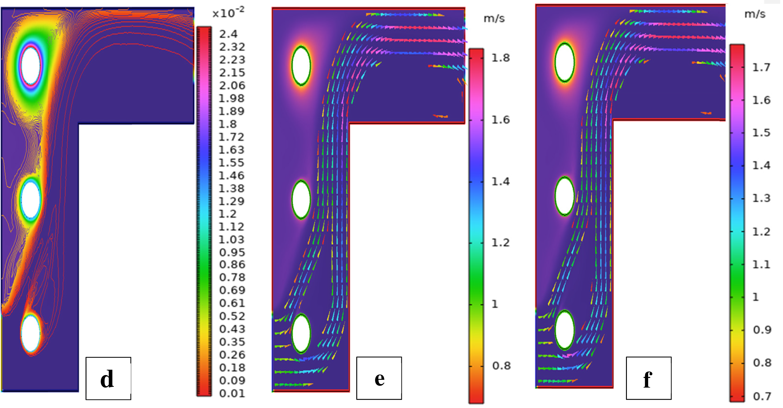
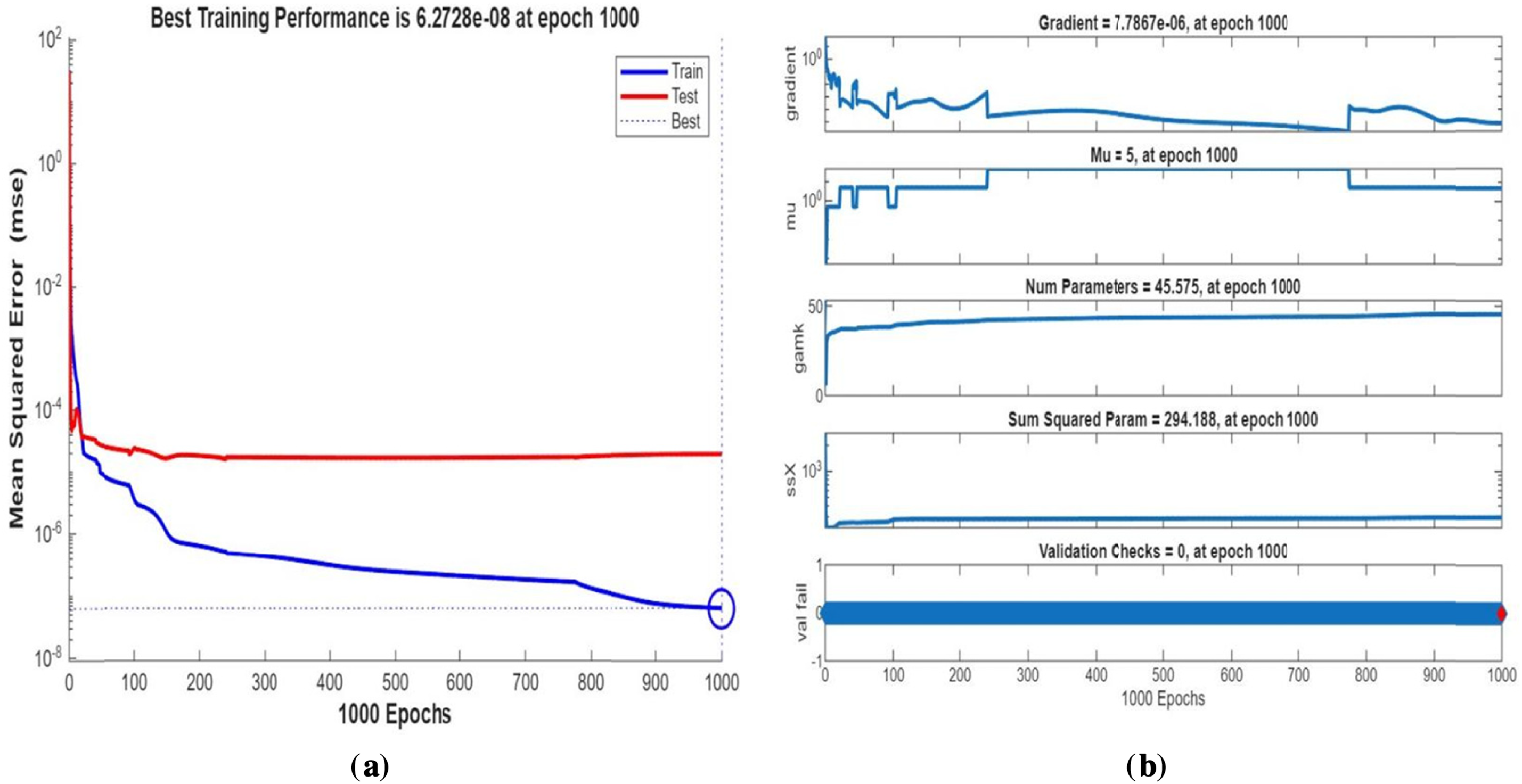
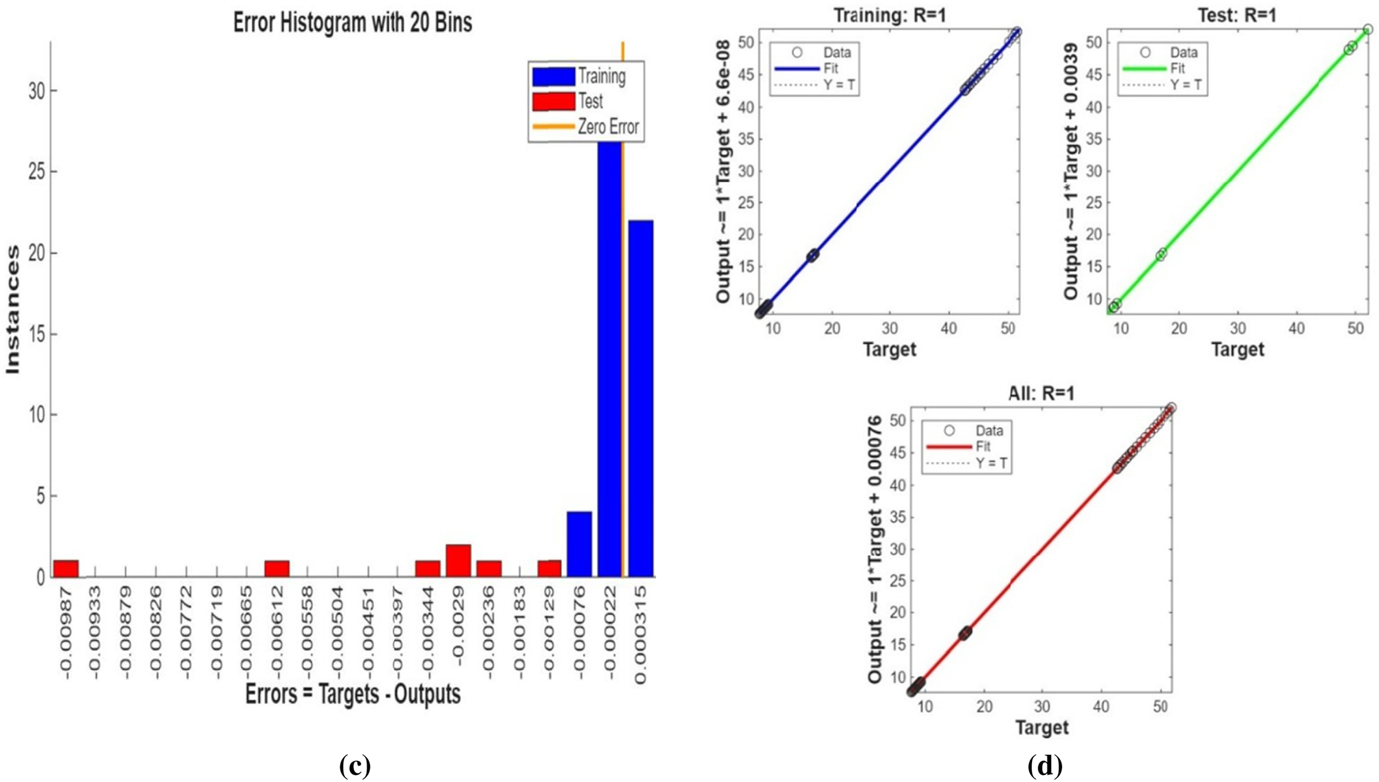
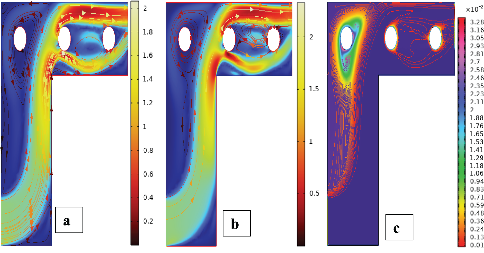
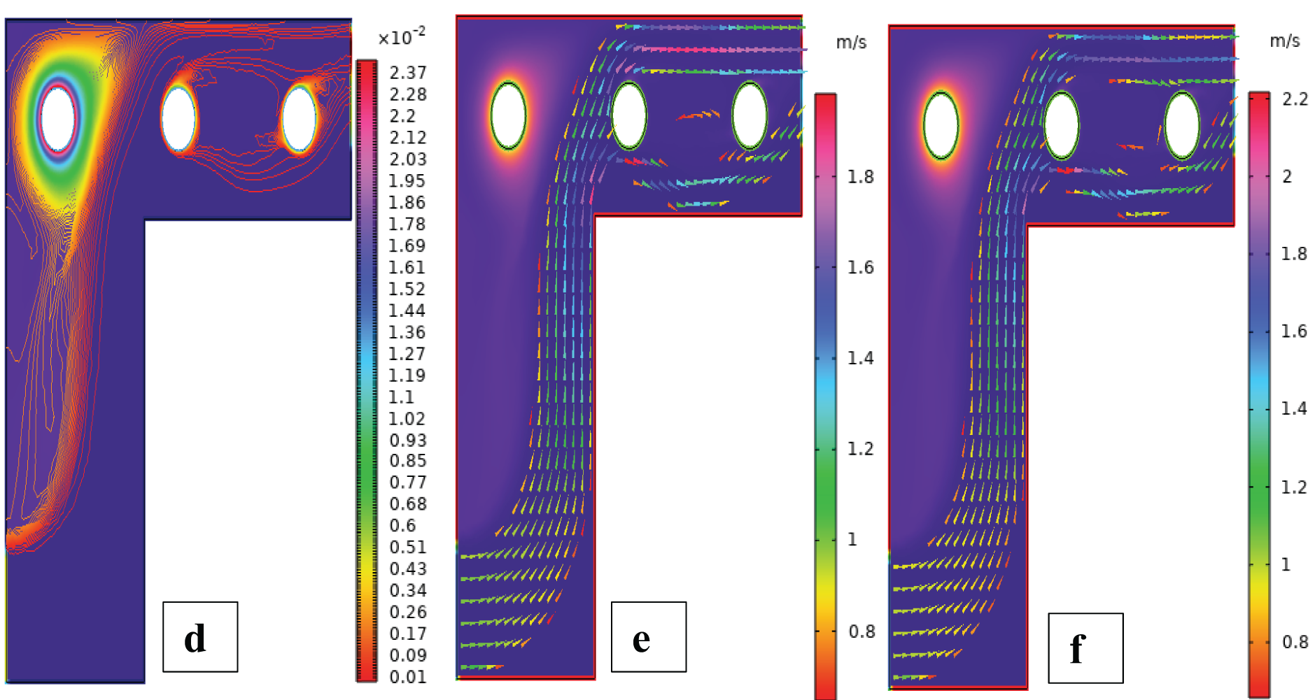
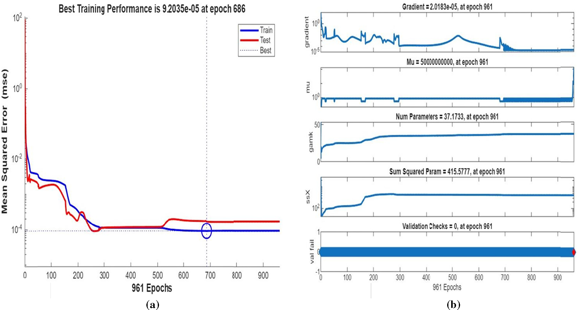
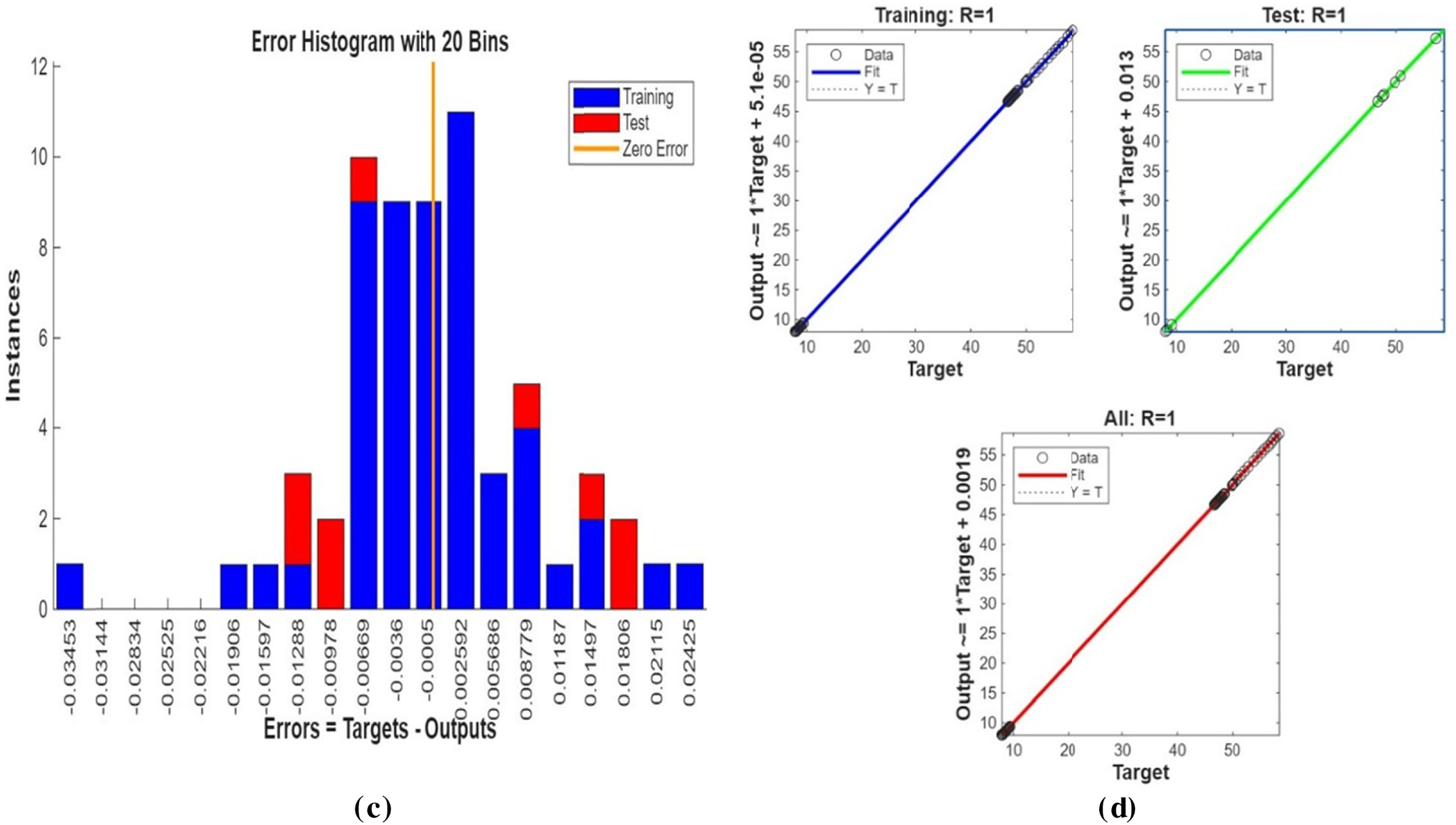
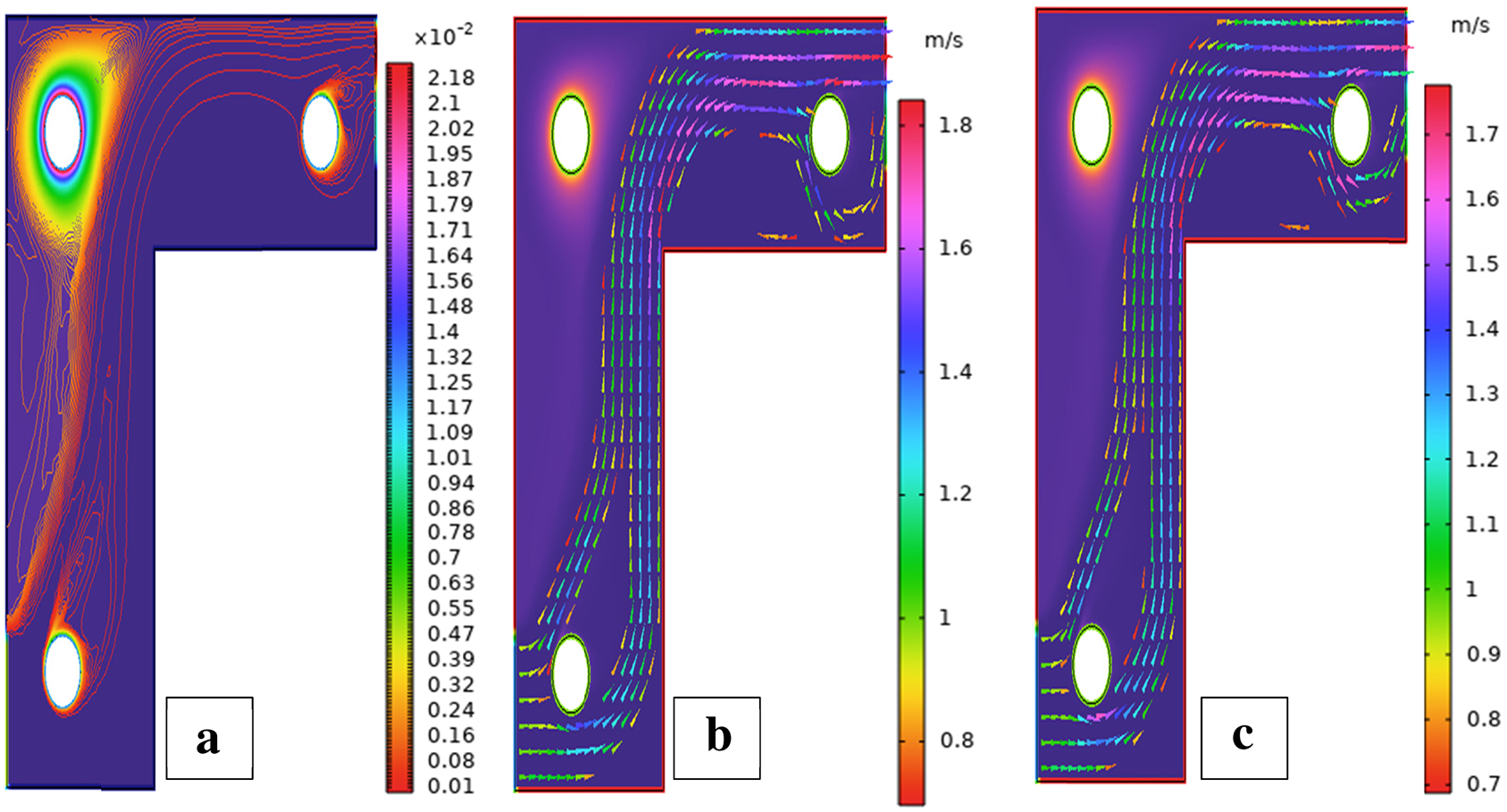

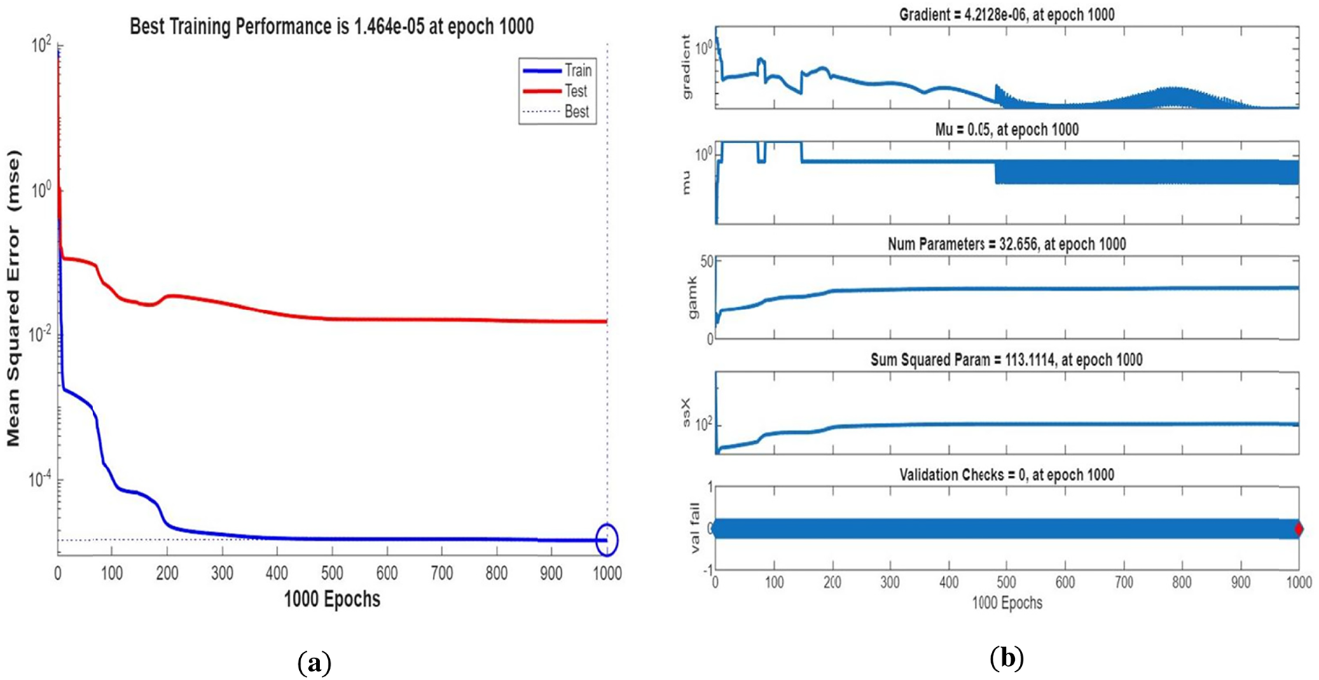
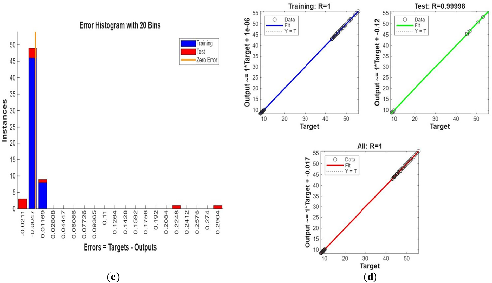

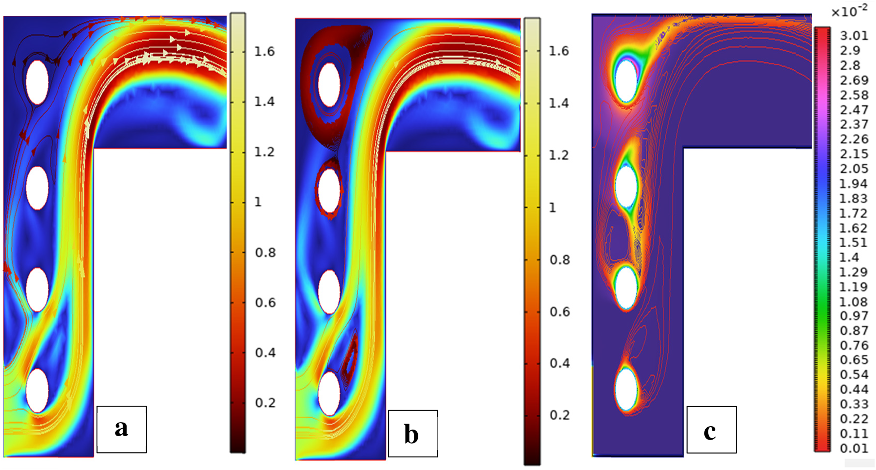

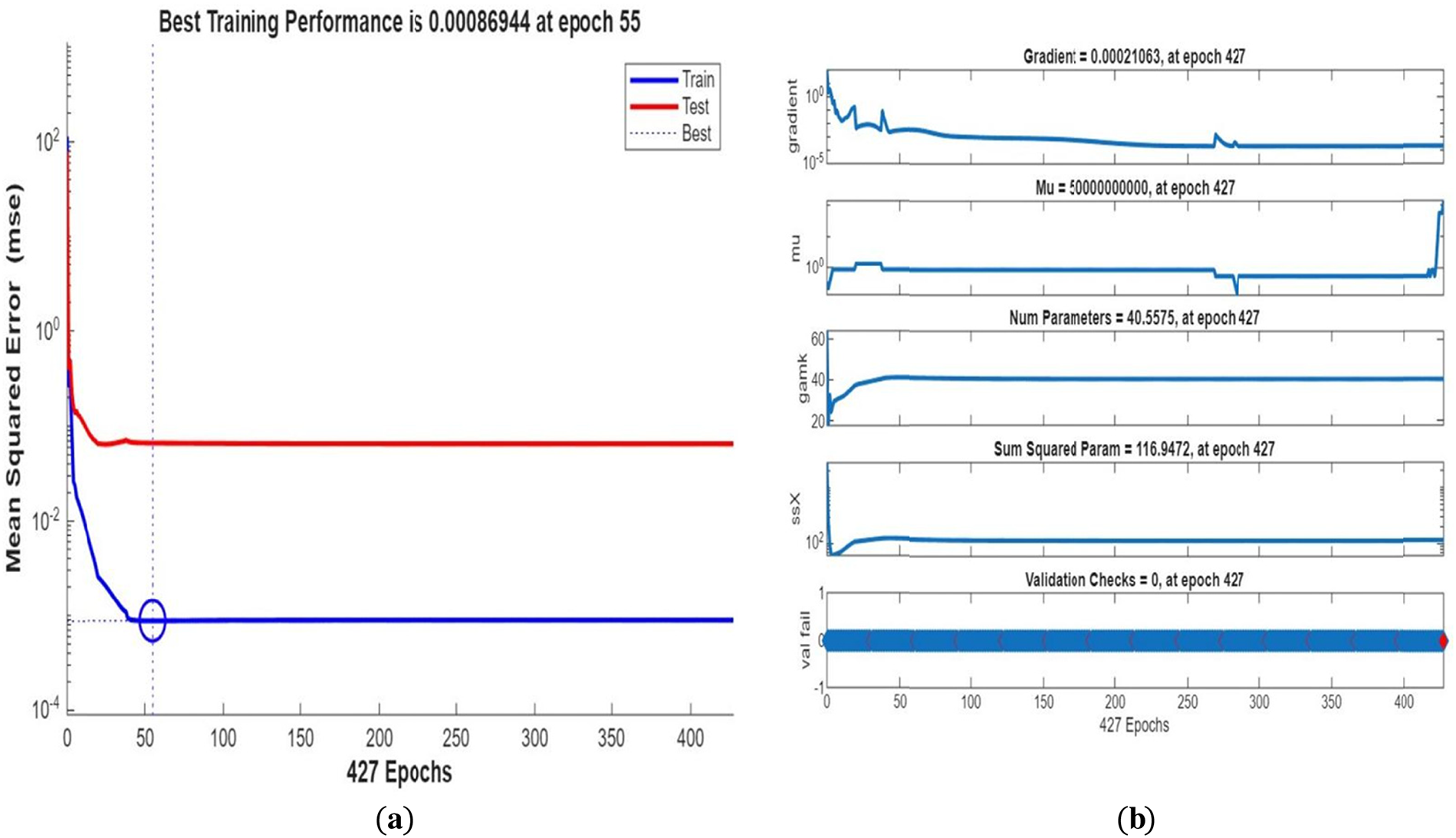
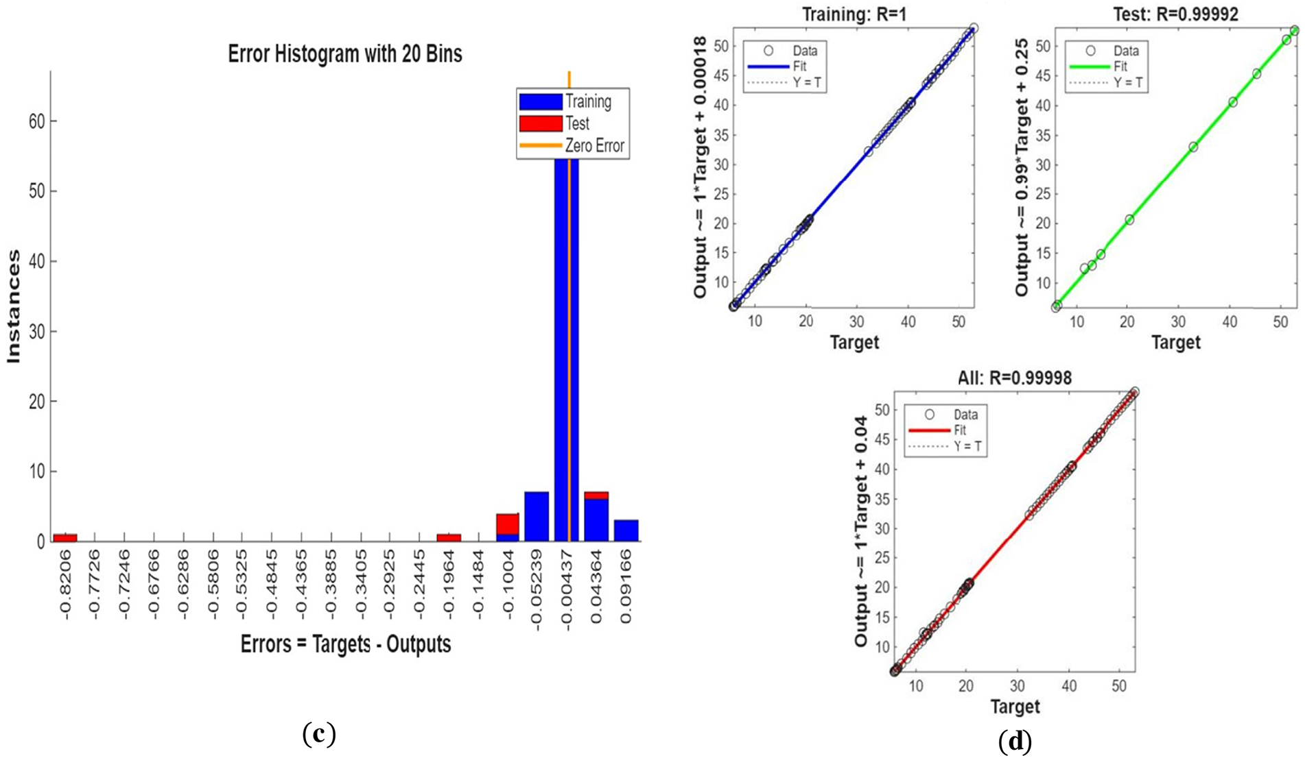
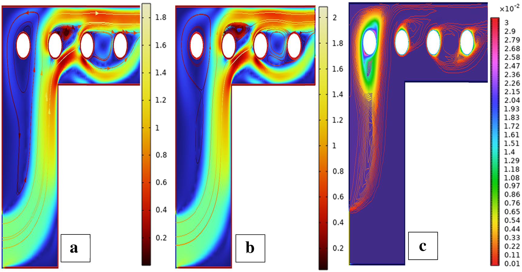
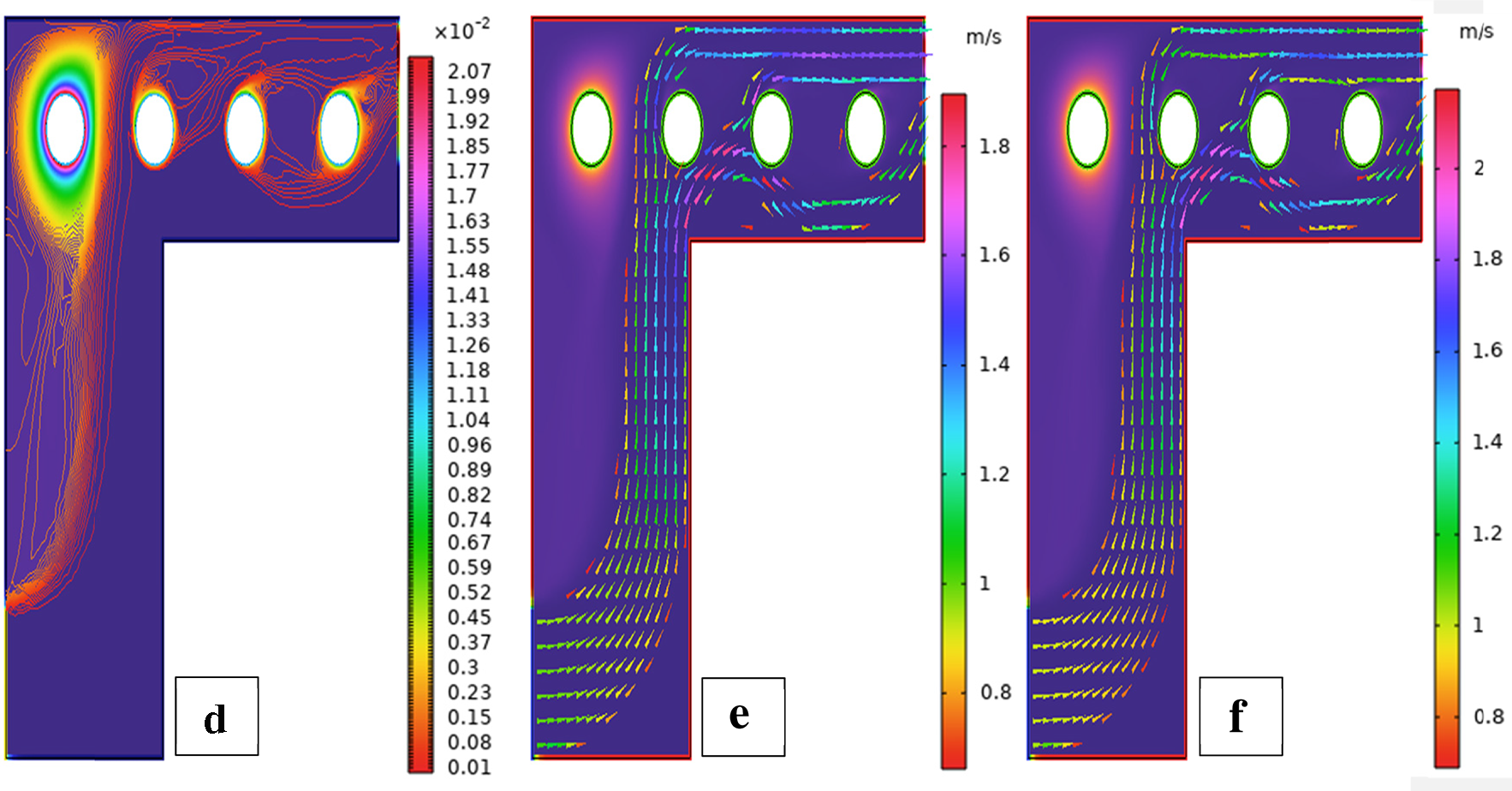
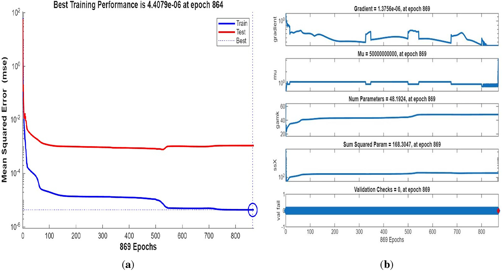
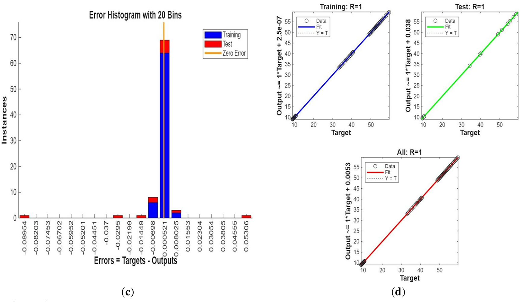
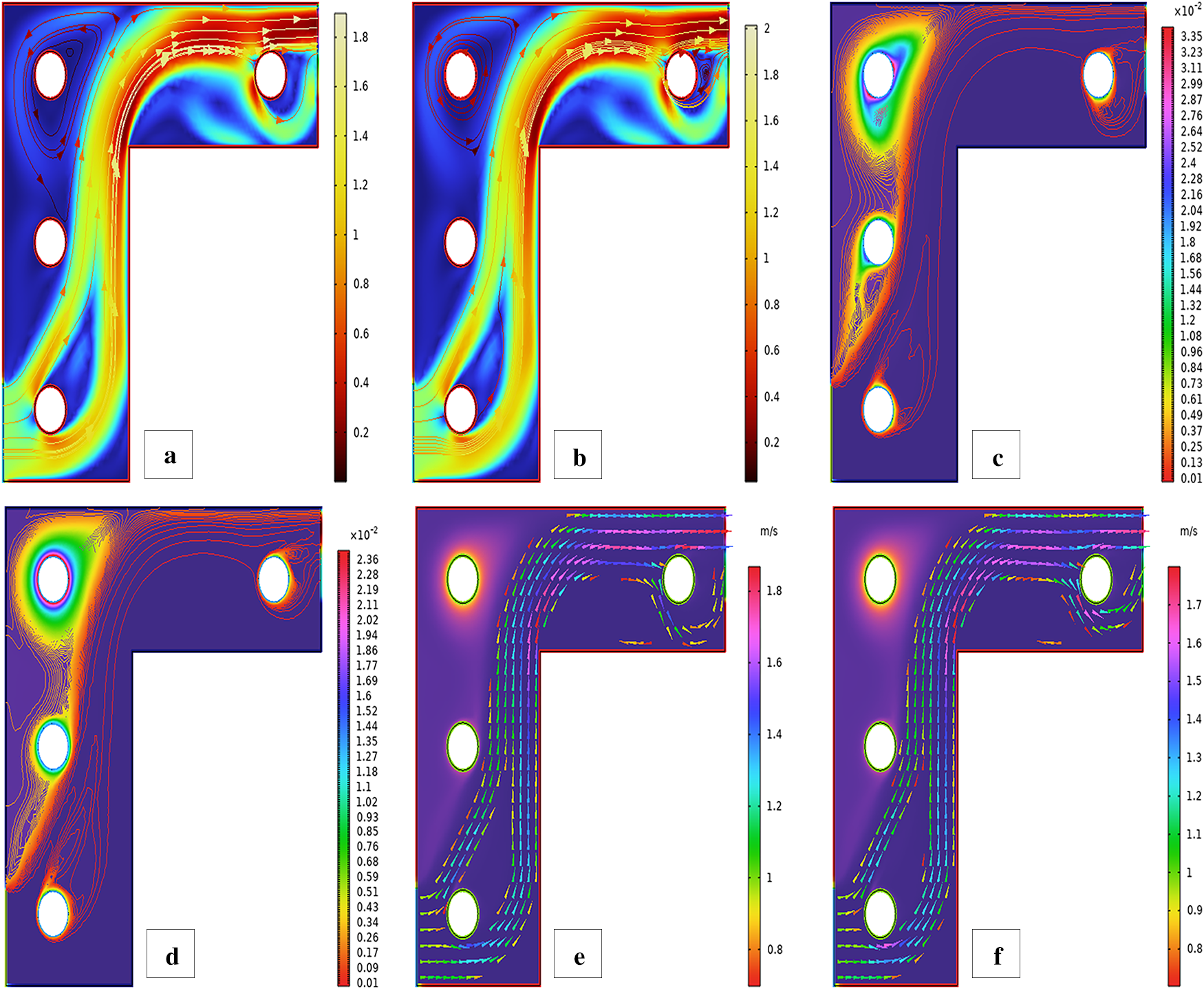
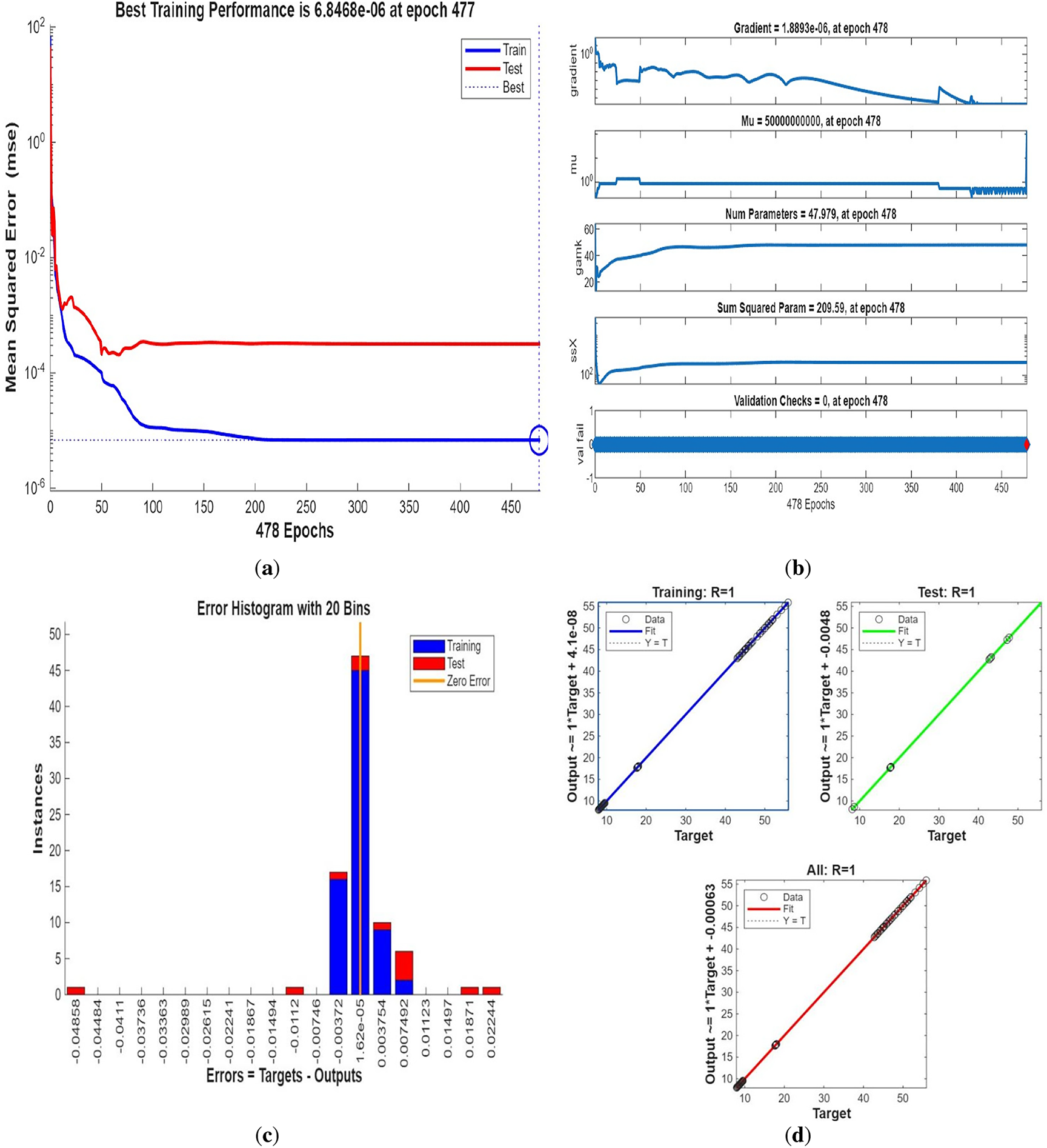

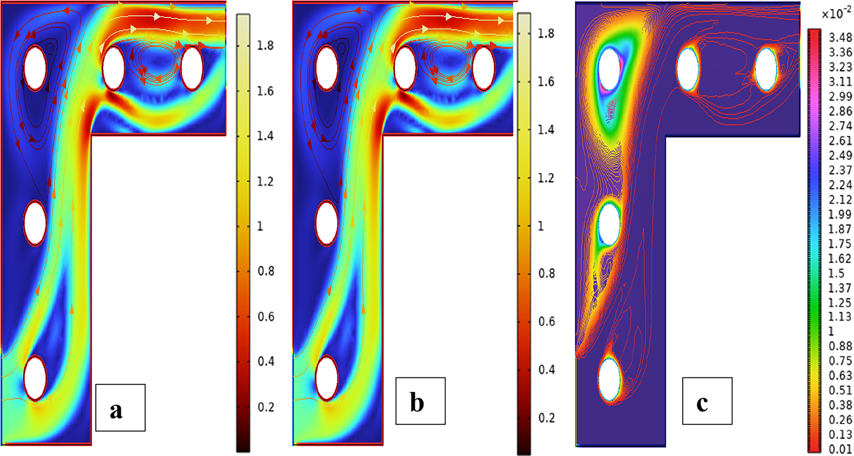
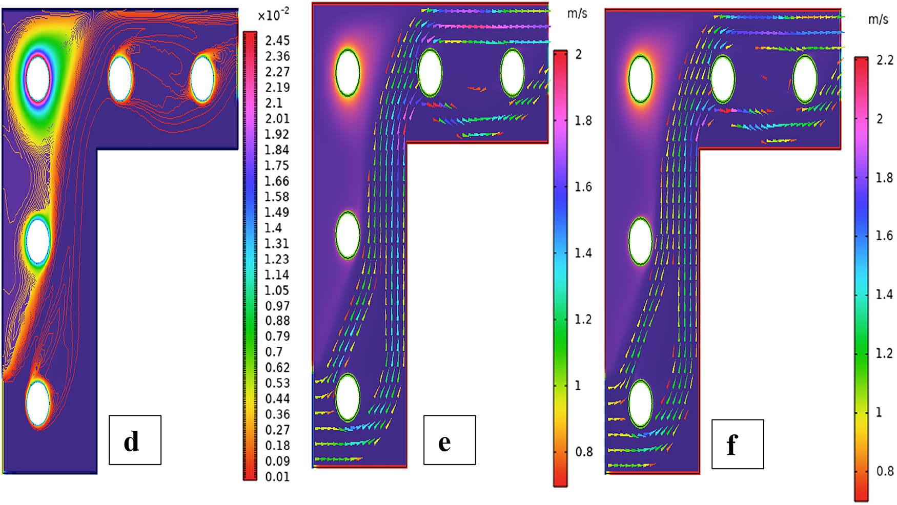
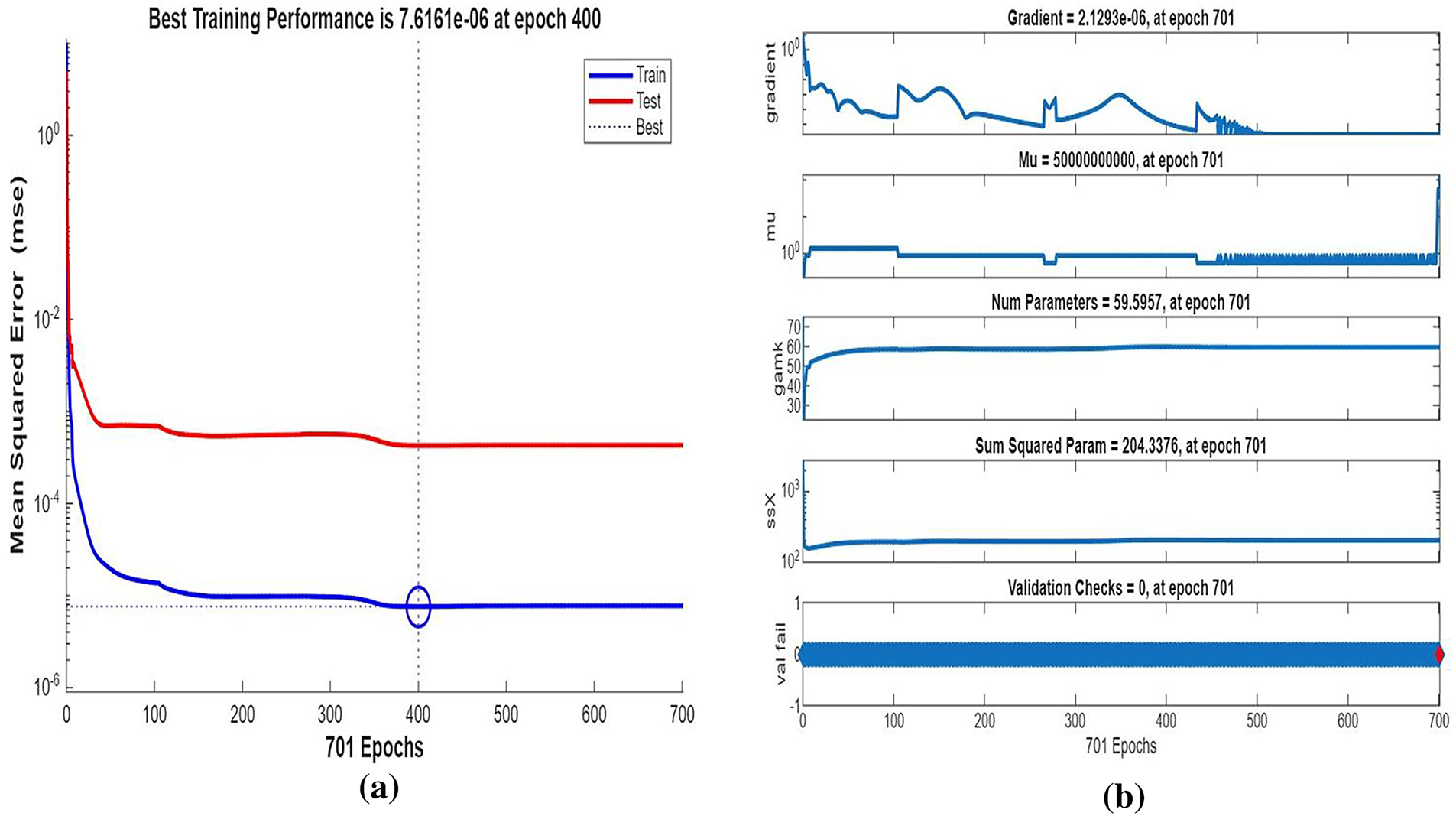


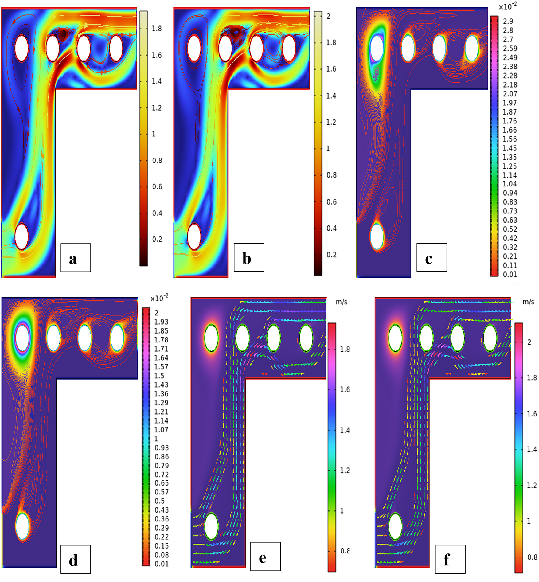
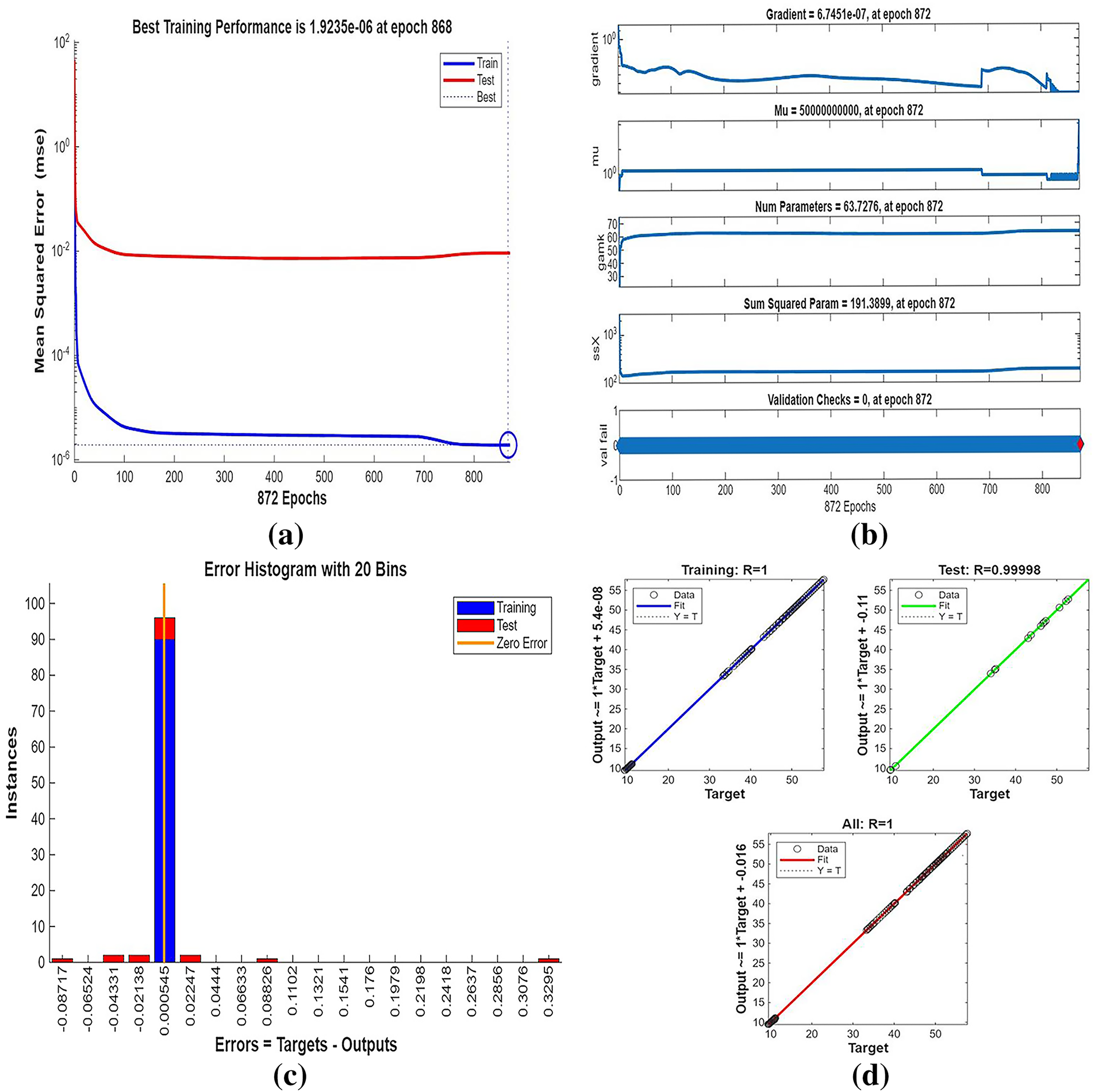

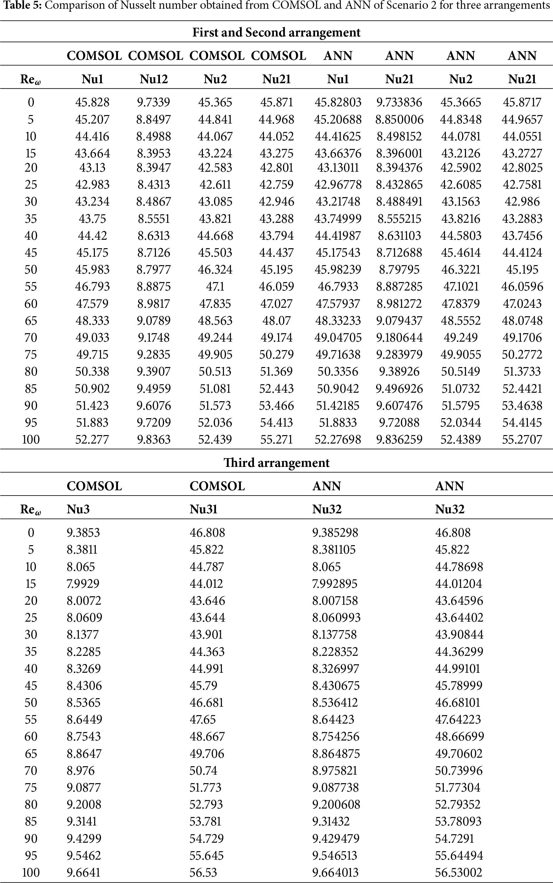
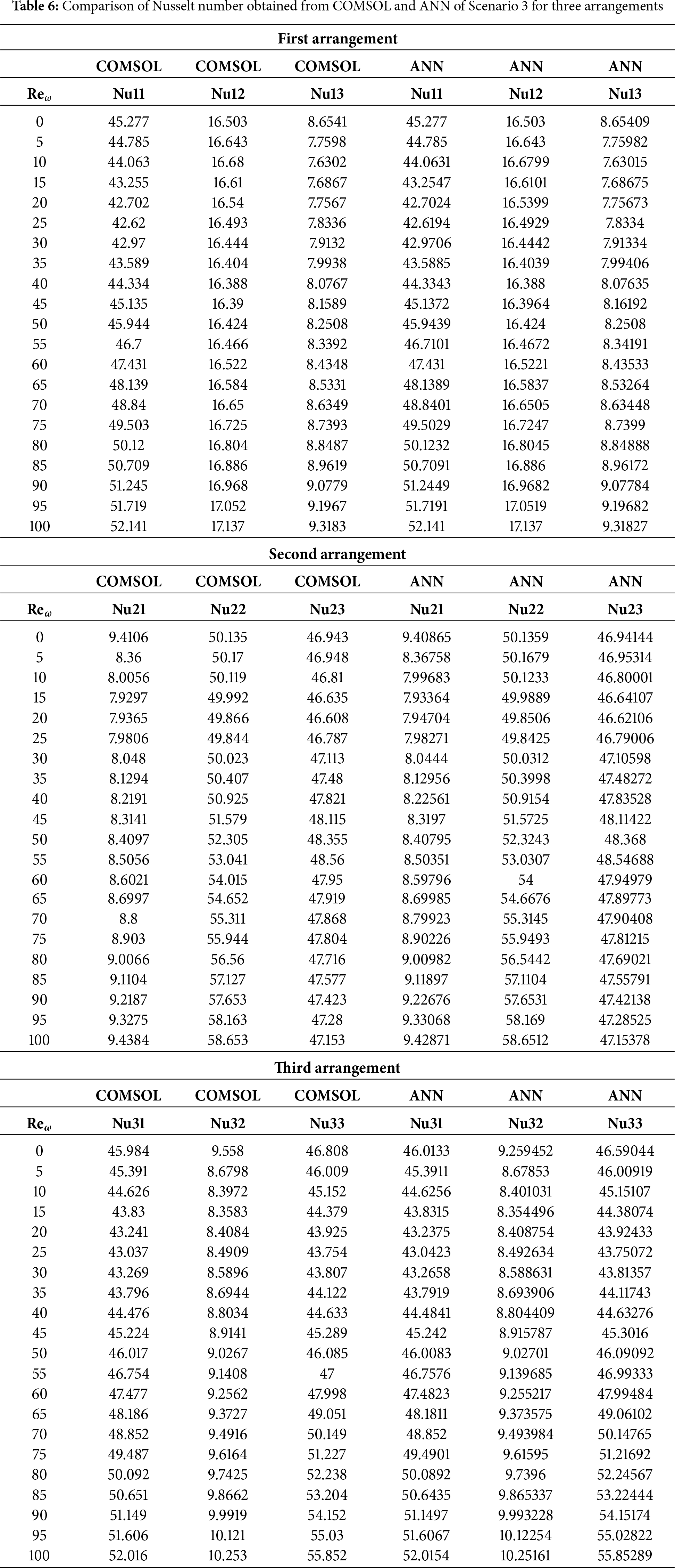

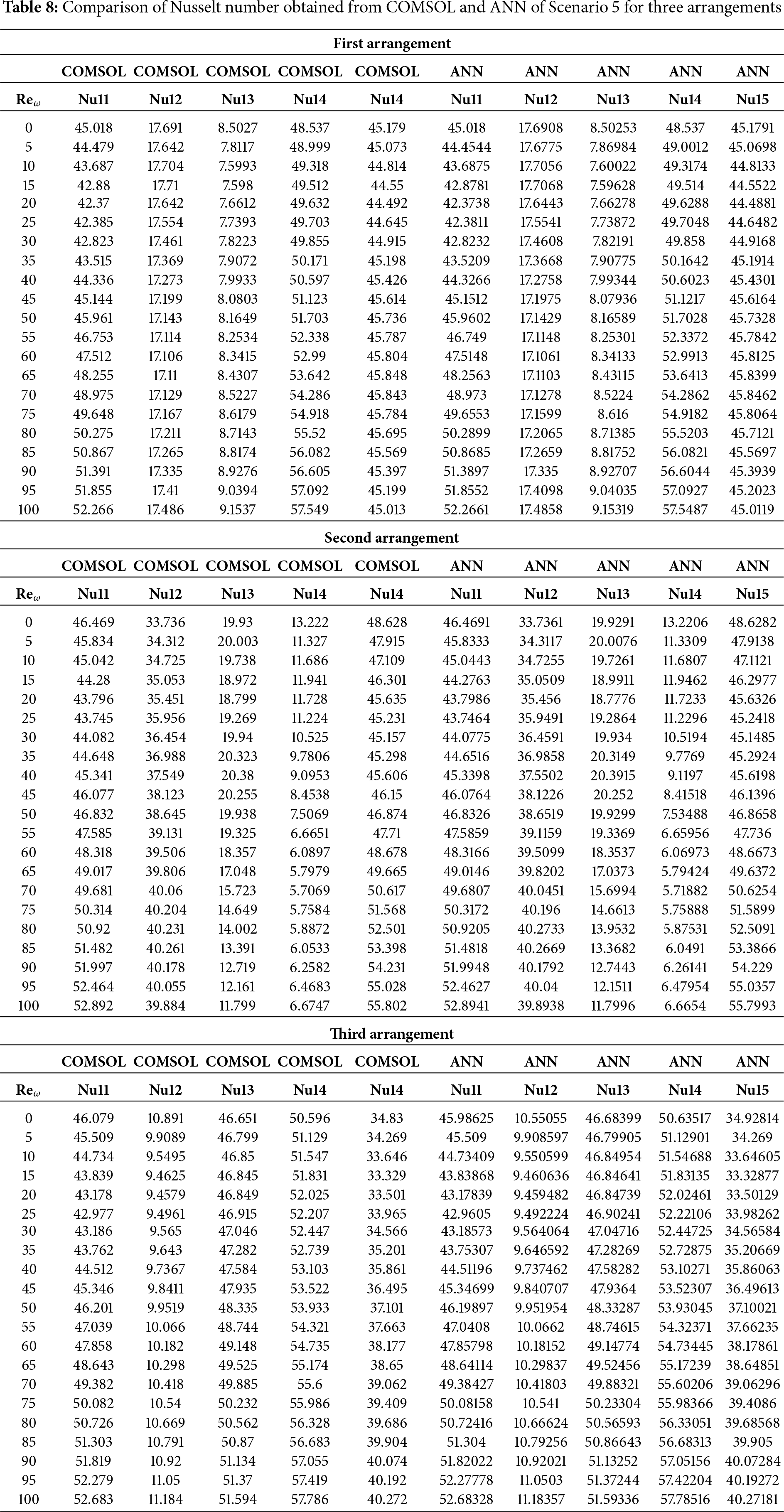
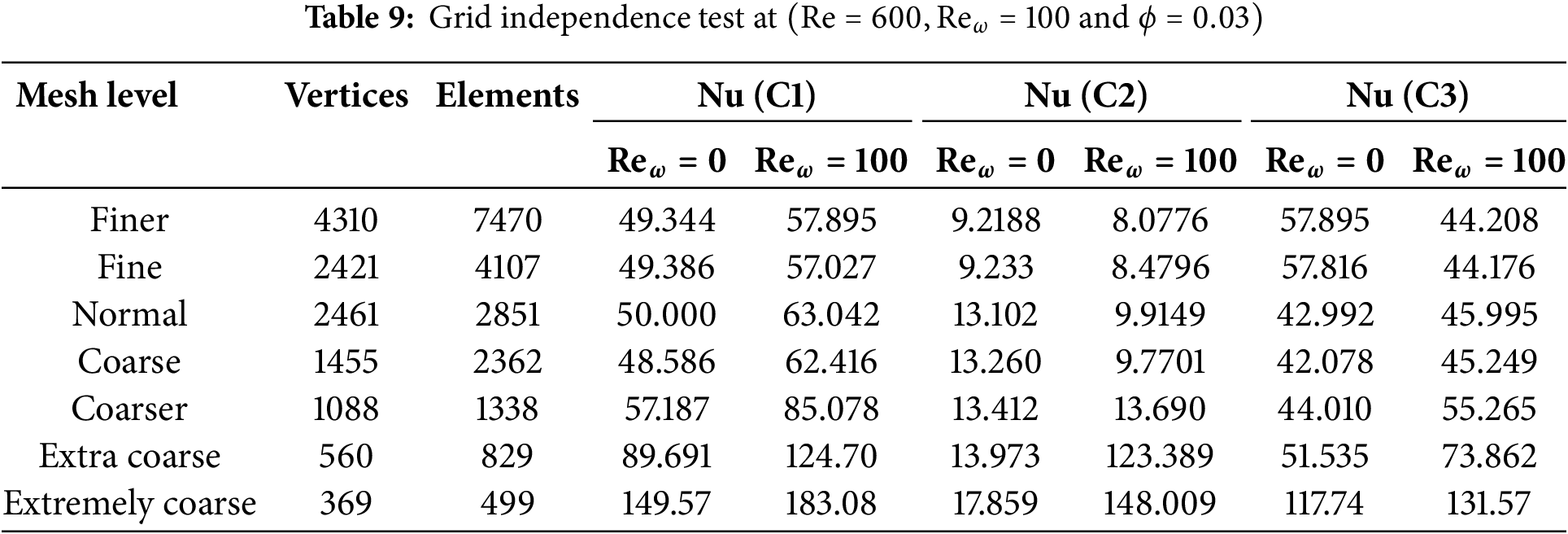

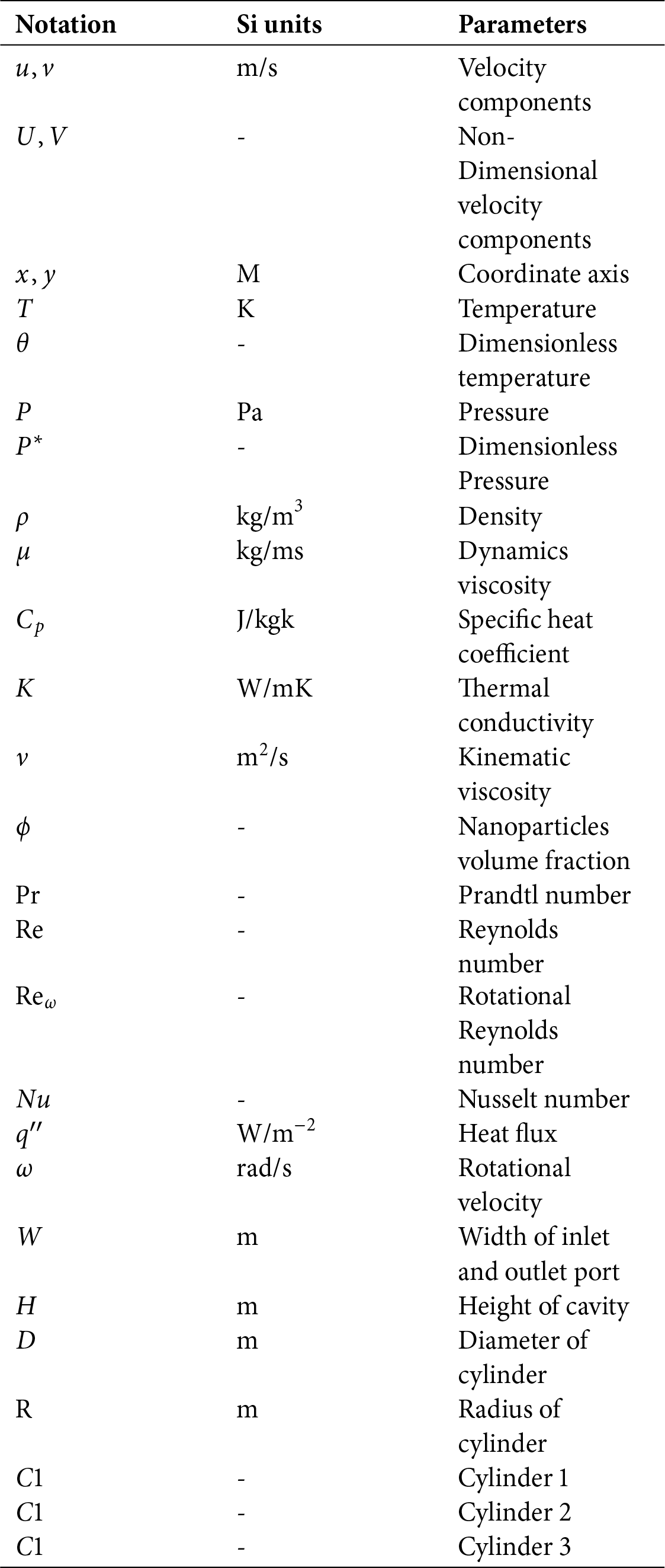
 Copyright © 2025 The Author(s). Published by Tech Science Press.
 Downloads
 Citation Tools