
 Submit a Paper
 Propose a Special lssue
 Open Access
ARTICLE
An Embedded Computer Vision Approach to Environment Modeling and Local Path Planning in Autonomous Mobile Robots
Computer Engineering Department, Bilecik Şeyh Edebali University, Bilecik, 11100, Türkiye
* Corresponding Author: Hakan Üçgün. Email:
(This article belongs to the Special Issue: Environment Modeling for Applications of Mobile Robots)
Computer Modeling in Engineering & Sciences 2025, 145(3), 4055-4087. https://doi.org/10.32604/cmes.2025.072703
Received 02 September 2025; Accepted 11 November 2025; Issue published 23 December 2025
 View Full Text
 Download PDF
Abstract
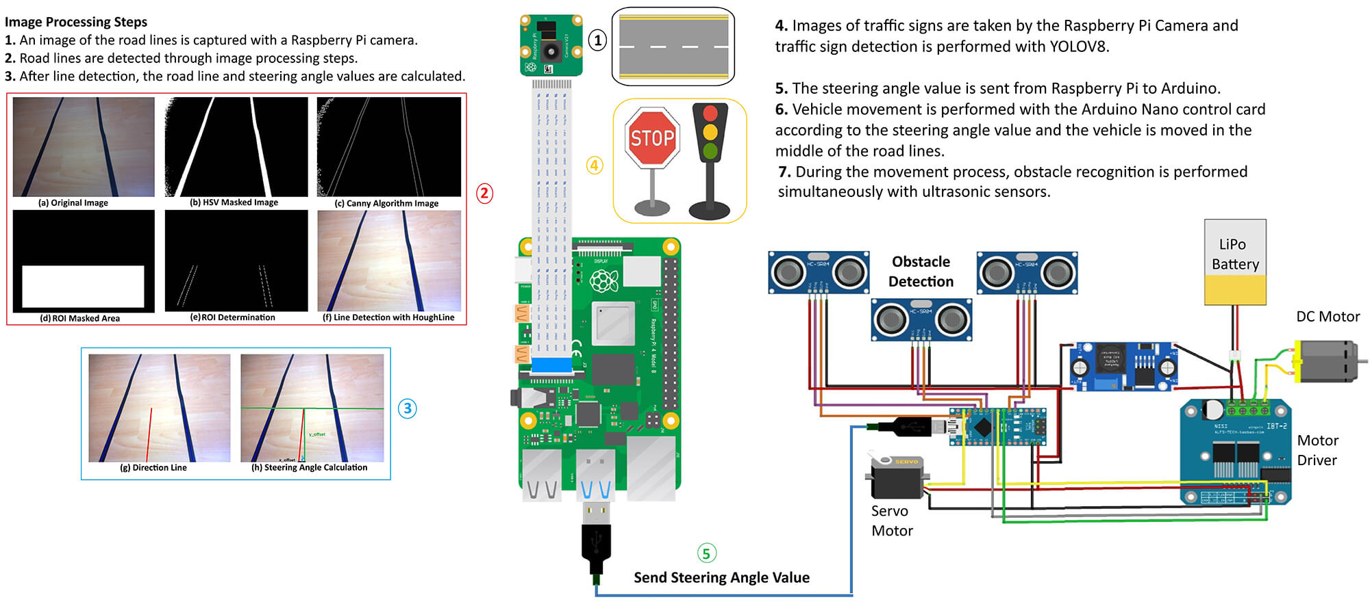
Recent advancements in autonomous vehicle technologies are transforming intelligent transportation systems. Artificial intelligence enables real-time sensing, decision-making, and control on embedded platforms with improved efficiency. This study presents the design and implementation of an autonomous radio-controlled (RC) vehicle prototype capable of lane line detection, obstacle avoidance, and navigation through dynamic path planning. The system integrates image processing and ultrasonic sensing, utilizing Raspberry Pi for vision-based tasks and Arduino Nano for real-time control. Lane line detection is achieved through conventional image processing techniques, providing the basis for local path generation, while traffic sign classification employs a You Only Look Once (YOLO) model optimized with TensorFlow Lite to support navigation decisions. Images captured by the onboard camera are processed on the Raspberry Pi to extract lane geometry and calculate steering angles, enabling the vehicle to follow the planned path. In addition, ultrasonic sensors placed in three directions at the front of the vehicle detect obstacles and allow real-time path adjustment for safe navigation. Experimental results demonstrate stable performance under controlled conditions, highlighting the system’s potential for scalable autonomous driving applications. This work confirms that deep learning methods can be efficiently deployed on low-power embedded systems, offering a practical framework for navigation, path planning, and intelligent transportation research.Graphic Abstract
Keywords
Autonomous vehicles have been transforming intelligent transportation systems by enabling vehicles to navigate safely to their destinations without direct human intervention [1]. The history of autonomous driving systems has spanned nearly a century, with early concepts having evolved into today’s advanced autonomous vehicles thanks to significant advancements in computing, artificial intelligence, and sensor technologies. While the development in this field initially progressed at a relatively slow pace due to technological limitations, a rapid transformation has been witnessed over the last few decades. This transformation has brought the goal of fully autonomous vehicles significantly closer [2,3]. With multinational companies having entered the race to develop smart vehicles, autonomous vehicles have become increasingly realistic and feasible, and the global market is expected to reach $615 billion by 2026 [4].
Autonomous vehicles have been an impactful research topic in science and technology, greatly influencing social and economic development [5]. Recently, the rapid development of artificial intelligence has considerably promoted the advancement of unmanned driving, including driverless cars [6,7], unmanned ground vehicles [8,9], and unmanned aerial vehicles [10,11]. Deep learning and artificial intelligence (AI) have been extensively used in many application areas, such as computer vision [12], face recognition [13], emotion recognition [14], natural language processing [15], and automotive applications [16]. In this context, an increasing number of deep learning-based solutions have been presented in the field of autonomous vehicles, achieving outstanding results. These solutions have had a great impact on the autonomous driving revolution seen in both academia and industry today, and self-driving cars have begun to operate on public roads under laboratory development and test conditions [17]. Among these technologies, driverless cars have attracted increasing attention due to their significant economic impact [18].
Driverless vehicles utilize sensors, cameras, radars, and AI-based algorithms to perceive their environment, monitor critical components, and autonomously manage control, navigation, and decision-making [19,20]. These systems process visual and auditory data to build an environmental model that represents road conditions, traffic signs, and obstacles, enabling safe navigation. Based on this model, the decision-making unit determines speed, direction, and behavior to ensure effective driving strategies [20]. The ultimate goal is to enhance road safety and driving comfort by reducing or eliminating human intervention [21].
Despite significant progress in autonomous vehicle research, most existing studies rely on high-performance computing units and cloud-assisted architectures, which limit their applicability in real-world, resource-constrained environments. Furthermore, current literature often overlooks the integration of efficient computer vision models with low-cost hardware platforms such as the Raspberry Pi, resulting in a research gap concerning real-time perception and decision-making under limited computational resources. While several studies have explored deep learning-based traffic sign recognition and lane detection separately, there remains a lack of compact, reproducible systems that combine these tasks with effective sensor fusion for obstacle avoidance on embedded platforms. To address these gaps, this study presents a compact and energy-efficient autonomous vehicle prototype integrating real-time traffic sign recognition, lane detection, and obstacle avoidance using a Raspberry Pi 4 (8 GB RAM).
In this study, an autonomous RC vehicle prototype was developed by integrating computer vision, intelligent sensing, and embedded AI techniques to achieve lane keeping and obstacle detection. Lane detection was performed using image processing algorithms that identified road boundaries and calculated the lane midpoint, which was then converted into steering commands for real-time navigation. This integration provided a foundation for local path planning and autonomous control. In parallel, ultrasonic sensors enabled obstacle-aware navigation by measuring surrounding distances; when an obstacle was detected within 30 cm, the vehicle was stopped to ensure safety. By combining lane keeping and collision avoidance, the proposed system demonstrates how lightweight AI models and sensing technologies can enhance safety and efficiency in resource-constrained platforms. Experimental evaluations confirmed stable performance under different scenarios, highlighting both strengths and limitations, while offering insights for future improvements in autonomous mobility and real-time navigation systems. The contributions of this article have been summarized as follows:
1. A camera and embedded system based autonomous vehicle prototype has been developed that integrates AI-assisted sensing and decision-making processes onto a physical platform. This approach has offered a multidisciplinary contribution by integrating the fields of image processing and robotic motion control.
2. The system demonstrates a seamless integration of conventional image processing methods—including lane detection, region of interest (ROI) determination, and slope analysis—with real-time steering control. This confirms that traditional computer vision techniques can effectively complement AI-based models, ensuring robust and adaptive navigation for resource-constrained platforms.
3. The implementation and experimental validation of the YOLOv8 deep learning model for traffic sign recognition (red, yellow, green, and stop signs) highlights its practical applicability to real-world autonomous driving tasks.
The structural organization of this study has been presented as follows: Section 2 provides a comprehensive review of the current literature, focusing on autonomous vehicle systems, image processing, and deep learning-based traffic sign recognition. Section 3 details the hardware components, software infrastructure, and methodological approaches employed. Section 4 presents the implementation steps, testing procedures, and experimental results in detail. Section 5 offers a technical evaluation and discussion of the system’s performance. Finally, Section 6 summarizes the general findings and outlines potential directions for future improvements and developments.
In recent years, autonomous vehicle technologies have become a significant research topic in both academic and industrial fields. These vehicles are defined as systems capable of operating safely by sensing their environment without human intervention. They offer significant advantages, particularly in terms of transportation safety, sustainability, and comfort, and can potentially benefit society and urban infrastructure [22,23]. The literature emphasizes that autonomous driving systems can significantly improve traffic safety by reducing human-induced errors. In fact, approximately 94% of traffic accidents have been reported to be caused by driver errors such as inattention, negligence, or violations of rules. Eliminating risks such as distraction or drunk driving by autonomous systems offers significant potential for safe driving [24]. Therefore, many technology companies and research institutions are increasing their investments in automated driving systems and conducting multidisciplinary studies in this area [25]. Autonomous vehicles develop environmental awareness by processing data obtained from a wide variety of sensing units, such as cameras, LiDAR, radar, ultrasonic sensors, and GPS. These data are processed by AI-based decision mechanisms in the vehicle, and driving decisions are made autonomously [17]. This process requires the integration of many technological components such as sensor fusion, computer vision, localization, path planning, and deep learning [25].
2.1 Image Processing Techniques
When reviewing studies based on image processing on autonomous vehicles, applications that involve processing and analyzing visual data captured by cameras and other sensors to tracking driver movements [26,27], detect lane markings [28], tracking pedestrians [29], identify road irregularities [30], identify traffic signs [31] and self driving [32] stand out. Shubham et al. [33] proposed a driver assistance system integrating artificial intelligence, the Internet of Things (IoT), and computer vision to enhance driver comfort and safety. The system collects real-time data through cameras and sensors, performs driver authentication via facial recognition, and includes safety features such as drowsiness detection. It also supports obstacle detection, traffic sign and lane tracking, gesture-based media and call control, and music recommendations through sentiment analysis, thereby improving both safety and user experience. Prashanth et al. [34] designed a Raspberry Pi–based drowsiness detection algorithm utilizing the facial_68_landmark model. The method employs eye aspect ratio (EAR) thresholds, detecting fatigue when EAR < 0.25 and drowsiness when EAR < 0.15. Tested on 10 volunteers, the system achieved 97% accuracy and maintained robustness despite variations such as eyeglass use. Further evaluations on 400 test frames under different imaging conditions yielded 96% accuracy. Safety was enhanced by MQ3 alcohol sensors, vibration monitoring, and ultrasonic-based collision detection. In the event of alcohol detection or accidents, GPS modules transmitted location data in real time, demonstrating the system’s practical potential for driver safety. Garg et al. [35] developed a simulation-based software model to demonstrate the feasibility of autonomous vehicle technologies. The prototype integrates artificial intelligence, computer vision, and deep neural networks to perform tasks such as mapping, object tracking, parking space detection, lane changes, autonomous U-turns, and obstacle avoidance. Simulation results showed stable performance, with the vehicle operating at speeds up to 30 km/h and successfully avoiding collisions. Positional and angular data were effectively captured using both polar and Cartesian coordinates, validating the model’s capability for safe autonomous navigation.
2.2 Deep Learning and Machine Learning Model
When deep learning and machine learning-based artificial intelligence studies on autonomous vehicles are examined, applications related to training processes on datasets and models such as driver status monitoring [36], vehicle speed detection [37], parking management [38], steering angle estimation [39], accident detection [40], and damage detection [41] stand out. Advanced techniques such as convolutional neural networks (CNNs), object detection models (e.g., YOLO, Faster R-CNN), and semantic segmentation are widely used to improve detection accuracy [32]. Pranesh Kulkarni et al. [42] developed an integrated system combining lane and object detection. The approach merges YOLOv5 for object detection with a sequential CNN specifically designed for lane detection, enabling simultaneous identification of lane boundaries and objects such as vehicles, pedestrians, and traffic signs. Isa et al. [43] proposed a real-time traffic sign recognition and driver alert system using a Raspberry Pi 3. A total of twenty traffic sign images belonging to five different traffic sign classes were evaluated as part of the real-time application. The performance of the developed system was tested in terms of accuracy, latency, and reliability criteria. Utilizing TensorFlow, the system identified traffic signs from video streams across five classes with twenty sample images. Evaluations demonstrated over 90% average accuracy, with a maximum latency of 3.44 s at 50 km/h. Liu et al. [44] introduced PDT-YOLO to address challenges in multi-scale object detection, hidden target misses, and edge deployment in smart roadside systems. The algorithm was validated on DAIR-V2X-C and IVODC datasets, as well as in real traffic using ROS at 90 FPS. Results indicate that PDT-YOLO outperforms common algorithms with higher accuracy, smaller model size, fewer parameters, and faster inference. Narayanan et al. [45] developed a system to reliably detect distracted drivers using the Xception model. While the model, with an accuracy rate of 85.58%, performed slightly lower than models such as ResNet and VGG16, which have accuracies over 90%, it demonstrated superiority in real-time detection applications. It was noted that ResNet and VGG16 models experienced more difficulties in practice due to overfitting problems, and this could be explained by the Xception model’s better ability to capture complex features. Ramazhan et al. [46] proposed an enhanced YOLOv9 architecture for detecting six vehicle damage types. Integrating a Convolutional Block Attention Module (CBAM) and using the SCYLLA-IoU (SIoU) loss function improved model focus and bounding box regression. The study also introduced the Damage Severity Index (DSI), quantifying damage severity by combining the number of damages, damage-to-image ratio, confidence scores, and damage type. Experiments on the CarDD dataset showed a 1.75% accuracy improvement over existing YOLO models, with DSI providing a useful tool for informed repair decision-making.
2.3 Embedded Control Systems for Autonomous Vehicles
When examining general studies on autonomous vehicles, applications such as robot operating systems (ROS) [47], SLAM-based mapping and localization [48], Advanced Driver Assistance Systems (ADAS) [49], and Lidar-based sensing applications [50] stand out. Autonomous driving generally focuses on inferences derived from perception processes performed with multi-sensor structures [51]. Hijji et al. [52] developed a multi-agent prototype combining multiple sensors with a Raspberry Pi to enhance autonomous vehicle navigation. The system integrates an ultrasonic sensor, a 160∘ wide-angle SonarSpinner, a vision sensor for guidance and traffic sign detection, and an infrared obstacle sensor with a 150 cm threshold. A virtual reality-based simulator was used for training and evaluation. Knowledge distillation from an Nvidia-based teacher model produced a lightweight student model suitable for end devices, while a custom Haar Cascade classifier achieved high accuracy in traffic sign detection, contributing to fast and efficient navigation. Shaik et al. [53] designed and implemented an electric vehicle (EV) control system supporting both manual and autonomous operation. In autonomous mode, a Raspberry Pi 5 board manages steering and motion via sensors and actuators. LIDAR-Lite v3HP ensures obstacle detection and speed adjustment, a rotary encoder provides steering angle and direction, and PWM signals control motor speed through a worm gear steering mechanism. The system was tested in a controlled campus environment, demonstrating successful basic autonomous driving capabilities. Dai et al. [54] proposed a SLAM and online localization method based on multi-sensor fusion for smart electric vehicles. The system employs a 32-beam LiDAR, RTK-GNSS, and IMU sensors. Front-end mapping uses Normal Distribution Transform (NDT) registration, loop closure detection, and RTK-GNSS positioning, while back-end pose graph optimization eliminates drift and generates an optimized map. During localization, an Error State Kalman Filter (ESKF) fuses LiDAR data with vehicle states, achieving high-precision positioning. Validation on the KITTI dataset and field tests showed mapping accuracy of 5–10 cm and positioning accuracy of 20–30 cm, supporting online autonomous driving in complex environments. Rahman et al. [55] developed an Arduino-based robotic vehicle capable of gas and landmine detection in hazardous areas such as military zones or disaster sites. The robot navigates independently using gas sensors, a metal detector, and an ultrasonic system, and can notify users via GSM-based SMS or calls when threats are detected. Yadav Kanneboina et al. [56] created an autonomous vehicle using an ESP32 microcontroller with GSM, GPS, and multiple sensors. The system handles obstacle detection, route planning, and orientation, while transmitting real-time location information to users via text messages.
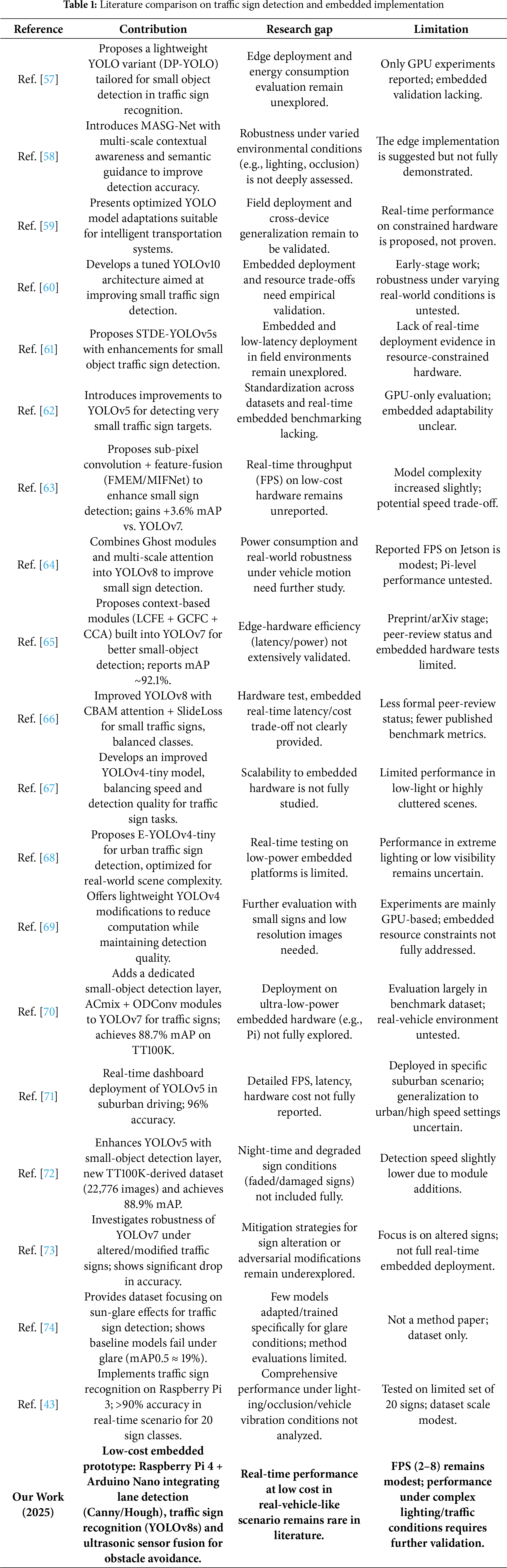
In the Related Work section has been significantly expanded to include a comparative analysis of 20 recent and relevant studies on real-time traffic sign detection and recognition. The comparison process was conducted by including sections on the contributions, research gaps, and limitations of the reviewed studies. In the revised version, a comparative summary table (Table 1) has been added. The literature review examined recent studies on real-time traffic sign detection and recognition. Inferences regarding the contributions, research gaps, and limitations of the reviewed studies are presented in Table 1.
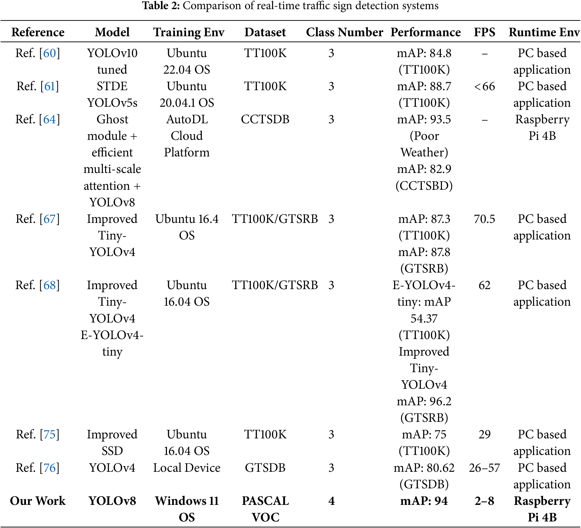
The second comparison, conducted within the literature review, was made according to multiple dimensions, such as the model or algorithm used in the studies (e.g., YOLOv5, YOLOv8, EfficientDet, and CNN-based hybrid approaches), dataset features (e.g., GTSRB, TT100K, and custom datasets), computational hardware (e.g., NVIDIA RTX GPUs, Jetson Nano, Raspberry Pi), classification accuracy, frame rate (FPS), and real-time processing capabilities. Table 2 provides a comparison table of performance metrics.
In this study, an autonomous ground vehicle prototype has been developed using embedded system boards and image processing techniques. The system is capable of performing road line tracking, traffic sign recognition, environmental sensing, and engine control tasks. The hardware components within the system include a Raspberry Pi 4, Arduino Nano, ultrasonic sensors, a servo motor, DC motors, and a camera module. The developed architecture is equipped with image processing and sensor fusion techniques and operates in real-time in an embedded system environment. A LiPo (Lithium Polymer) battery has been used as the power source.
The general block diagram of the system’s operating structure is shown in Fig. 1. Road image data obtained by the Raspberry Pi Camera Module is transmitted directly to the Raspberry Pi 4 device, where it undergoes various image processing steps. This process involves lane (road line) detection, and the orientation angle is calculated based on the position of the detected line. The calculated angle value is transferred to the Arduino Nano microcontroller via the serial communication protocol. Based on the angle information received, the Arduino Nano determines the vehicle’s direction by rotating the servo motor between 40∘ and 140∘. Additionally, the distance of obstacles around the vehicle is measured using three ultrasonic sensors integrated into the Arduino Nano. Capable of autonomously performing basic driving maneuvers and possessing obstacle detection capabilities, the vehicle is built on three key components: hardware architecture, data processing flow, and decision-making mechanisms. These key components are detailed in the following sections.
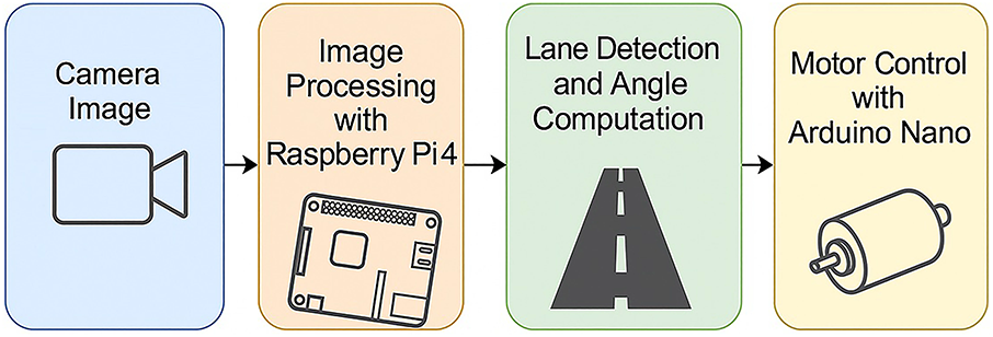
Figure 1: General block diagram of the system
The hardware infrastructure of the autonomous vehicle system developed in this study is built on two complementary core control units: Raspberry Pi 4 and Arduino Nano. Both microcontrollers perform specialized functions in terms of the system’s task distribution. Thanks to its high processing capacity and advanced input/output (I/O) capabilities, the Raspberry Pi 4 is configured as the system’s central control unit to perform computing-intensive tasks such as real-time image processing, road line detection, and object recognition. Meanwhile, the Arduino Nano, distinguished by its low power consumption and precise timing capabilities, is responsible for motor control operations, managing driving dynamics, evaluating environmental sensor data, and controlling actuators.
The system is equipped with three ultrasonic distance sensors to enhance environmental perception. These sensors are strategically placed at the front and sides of the vehicle, ensuring the functionality of obstacle detection and collision avoidance mechanisms. A Raspberry Pi Camera Module 3 is used to provide visual data flow. This camera module provides highly accurate data for detecting road markings and identifying traffic signs. For mobility, two DC motors located at the rear of the vehicle are responsible for the forward and reverse movement of the wheels. These motors are controlled by the Arduino Nano via a motor driver circuit, and speed adjustments are made using PWM (Pulse Width Modulation) signals. Steering of the vehicle is achieved by a single servo motor located on the front axle. This servo motor rotates according to the orientation angle calculated by the Raspberry Pi, ensuring the vehicle is guided along the specified route. As a result, each hardware component in the system plays a critical role in the data collection, processing, and decision-making cycle, directly impacting overall system performance and autonomous driving performance. Fig. 2 presents a schematic block diagram showing the interactions between the camera module, Raspberry Pi, Arduino Nano, servo motor, DC motor, and ultrasonic sensors in the system.
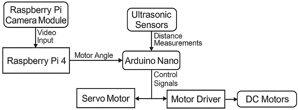
Figure 2: Embedded vision and ultrasonic sensing schematic diagram
3.1.1 Raspberry Pi 4 Control Board
Raspberry Pi is a low-cost, compact embedded computer system designed with a single-board structure. In this study, the Raspberry Pi 4 controller board was selected to perform image processing and object recognition operations on the autonomous vehicle and to provide overall control of the system. The board’s core is the Broadcom BCM2711 chip, built on a Harvard-based Reduced Instruction Set Computer (RISC) processor with a quad-core ARM Cortex-A72 architecture. The Raspberry Pi 4 offers a compact structure that houses all the components of a basic computer system. Available with different memory configurations (e.g., 4 GB and 8 GB of RAM), this model is equipped with numerous input/output (I/O) ports. With all these features, the Raspberry Pi 4 is considered a full-fledged computer on a small circuit board [77].
In this study, a Raspberry Pi 4 board processes images obtained from a camera to perform lane detection and image classification. During the lane detection process, lines on the road are detected and their angles relative to the x-axis are calculated. Furthermore, a deep learning model trained with TensorFlow Lite classifies the incoming images and determines information about the detected objects. All the obtained data is transmitted to the Arduino Nano microcontroller via a serial communication protocol. This allows the Raspberry Pi to perform both lane detection and object recognition, transmitting angle and object information to the Arduino Nano, ensuring the correct and secure operation of the system.
Arduino Nano is an integrated development board built on the ATmega328 microcontroller operating at a clock frequency of 20 MHz. Its compact design, low cost, energy efficiency, and ease of programming make it an ideal platform for embedded system applications and small-scale projects [78]. These features make Arduino Nano widely preferred, particularly for educational applications and the development of complex embedded systems.
In this study, the Arduino Nano board plays a critical role in the operation of the system. By processing the data transmitted by the Raspberry Pi 4 board, it enables the servo motor to rotate at the appropriate angle and control the speed of the DC motor. It also evaluates distance data obtained from the onboard ultrasonic sensors, enabling the vehicle to avoid obstacles. It also processes object detection information sent by the Raspberry Pi to respond appropriately to traffic signs and other objects. These versatile functions of the Arduino Nano ensure the safe and efficient operation of the system. In this context, the Arduino Nano serves as a central control unit within the project, contributing to the harmonious operation of all hardware components and supporting the success of the autonomous system.
3.1.3 Raspberry Pi Camera Module 3
The Raspberry Pi Camera Module 3 is equipped with a next-generation 12-megapixel Sony IMX708 image sensor. This module offers features such as a powerful autofocus mechanism, advanced low-light sensitivity, and high dynamic range (HDR) support. These features enable high-quality images even in low-light conditions, and the wide dynamic range allows for more vivid and detailed photos. The autofocus function allows for clear and sharp images to be easily obtained at different distances. The Raspberry Pi Camera Module 3 is considered an ideal solution for various Raspberry Pi projects, particularly for video recording, photography, and image processing applications [79]. In this study, the Raspberry Pi Camera Module 3 is used to capture instantaneous images of the road while the vehicle is in motion and transmit them to the Raspberry Pi 4 board.
3.1.4 Hardware System Experimental Setup
The proposed autonomous vehicle prototype was implemented on a Raspberry Pi 4 Model B, operating under Raspberry Pi OS (64-bit). The onboard processing handled both image acquisition and inference using the YOLOv8n model implemented in Python through the Ultralytics library. Visual data were captured via a Raspberry Pi Camera Module v2 (8 MP), while environmental awareness was achieved using three HC-SR04 ultrasonic sensors for obstacle detection. A dual L298N motor driver controlled two DC motors responsible for steering and propulsion. The system also utilized an I2C interface to read additional sensor inputs, and data synchronization was handled in real time. All modules were powered by a 12 V Li-ion battery pack with a 5 V regulator supplying stable power to the Raspberry Pi. This configuration ensures low power consumption, portability, and real-time processing performance between 2 and 8 FPS during operation. This integration combines the Raspberry Pi’s image processing capabilities with the Arduino Nano’s ability to manage environmental sensor data, creating an effective system that can be used in autonomous vehicle applications. The hardware connection diagram is shown in Fig. 3.
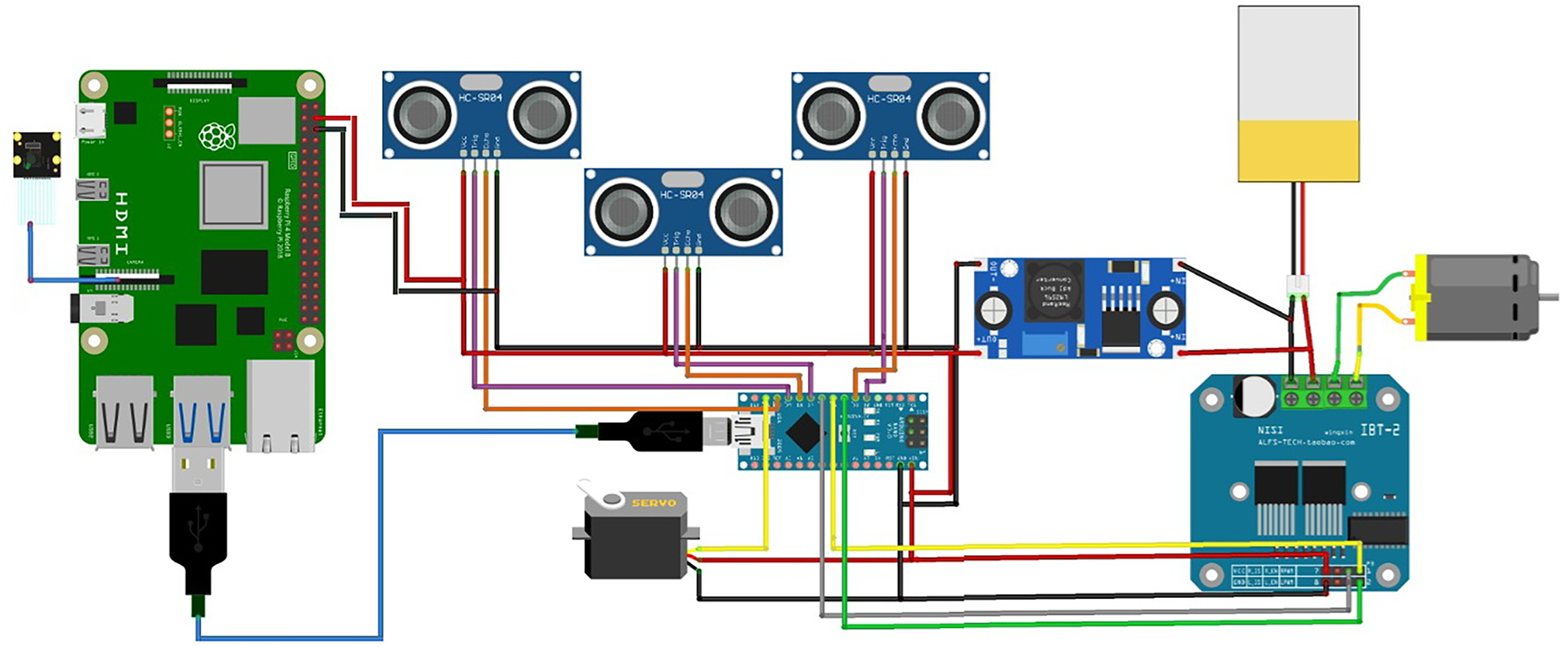
Figure 3: Hardware connection diagram
3.2 Lane Line Detection with Image Processing
In this study, advanced image processing techniques were utilized to ensure the autonomous vehicle system developed can navigate the road accurately and stably. The vehicle has an image processing pipeline consisting of a series of algorithms to perform road detection and line tracking functions. Fig. 4 presents the block diagram of the operations performed during the lane line tracking process. This process begins with the processing of images obtained using the Raspberry Pi Camera Module 3. The high-quality 1920 × 1080 resolution raw image captured by the camera module was downscaled to 640
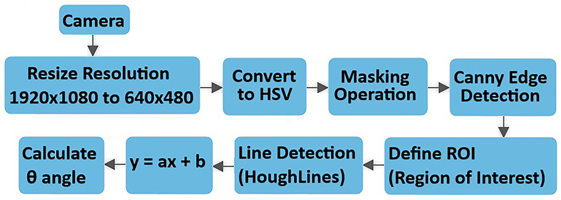
Figure 4: Lane detection process schematic diagram
The downscaled image is then converted to the HSV (Hue, Saturation, Value) color space. The HSV color model provides higher accuracy, particularly in color-based filtering and masking operations, by separately considering the hue, saturation, and brightness values of colors. After switching to this color space, a masking process is performed based on specific threshold values. In this process, pixels above a specified threshold are labeled white (1), and those below are labeled black (0), resulting in a binary image. This allows only regions with specific color characteristics to be highlighted. After masking, the image is subjected to the Canny edge detection algorithm for edge detection. Before this algorithm, the image is smoothed with a Gaussian filter to reduce noise and allow for clearer detection of target edges. The Canny algorithm performs gradient calculations on this smoothed image to identify sharp transitions and contours. Following edge detection, the system defines a specific ROI. This region focuses on the central portion of the road surface, ensuring only areas of interest are analyzed. During the ROI determination process, the logical AND operator is applied to the image, allowing only edges within the target region to be processed. This prevents unnecessary resource consumption. The Hough Transform (HoughLines) algorithm is applied to detect lines within the region of interest. This algorithm analyzes the points generated by edge detection and determines the linear lines formed by these points. The vehicle’s orientation is determined by creating an average line of direction from the numerous lines obtained. This average line is expressed in the form of a linear equation as y = ax + b.
In the final stage, the angular deviation (
3.2.1 HSV Color Space Masking Process
Color spaces are mathematical models that numerically represent the color components of digital images and play a crucial role in color separation, analysis, and manipulation in image processing. The HSV (Hue, Saturation, Value) model provides an intuitive representation by separating color into hue, saturation, and luminance, which is particularly advantageous when processing hue and luminance independently [80]. The components of the HSV color space are defined as follows:
• Hue: Represents the dominant color in an image, ranging from 0∘ to 360∘ to cover the full color spectrum, with each angle corresponding to a specific color.
• Saturation: Indicates color purity or intensity. A saturation of zero yields a completely gray color, while maximum saturation produces the most vivid representation.
• Value: Refers to the brightness of the color. Lower values darken the color towards black, whereas maximum values display the color at full brightness [80].
In this study, masking operations performed using the HSV color space, pixels within a specific color range are selected and marked as white (255); all pixels outside the selected range are defined as black (0). The resulting mask image highlights only regions containing the targeted color range. This approach is widely used in many image processing applications, such as lane detection, object tracking, and color-based segmentation. Fig. 5a shows the live image captured from the camera, while Fig. 5b shows the image converted to the HSV space.
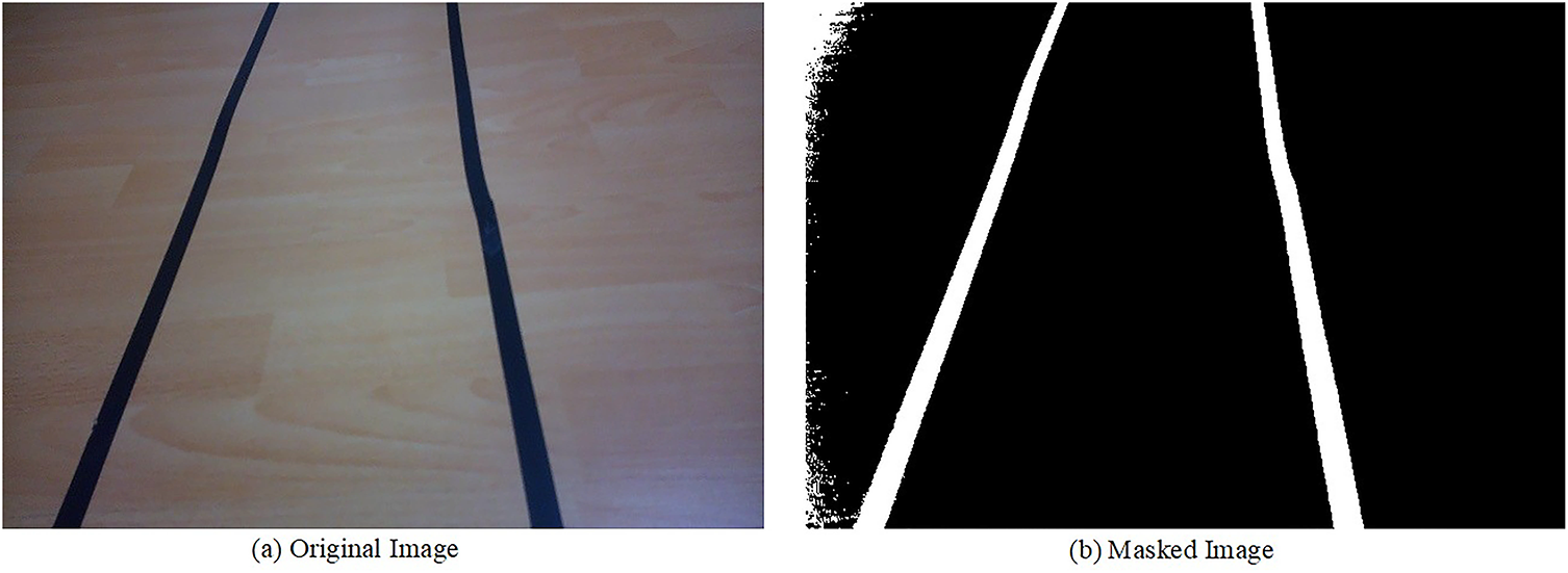
Figure 5: Original image conversion to HSV space
3.2.2 Canny Edge Detection Algorithm
The Canny edge detection algorithm, introduced by John F. Canny in 1986, is a multistage method widely employed to identify sharp and meaningful edges in digital images. Its popularity in computer vision arises from both high detection accuracy and robustness to noise, allowing the detection of even faint edges [81].
In the first stage of the algorithm, a Gaussian blur filter is applied to reduce high-frequency noise components in the image. This filter smooths the image, paving the way for a more stable edge detection process. The blurred image obtained with the Gaussian filter both reduces the effect of random noise and prevents defective pixels that may occur during edge detection. For color images, conversion to grayscale is performed prior to blurring. Following this preprocessing, the Canny algorithm detects edges by analyzing gradient changes and produces a binary output highlighting the detected edges [82].
In practical applications, the resulting edge map can be visualized for analysis. This process is crucial in image processing pipelines, particularly for tasks such as path tracking and object detection. Fig. 6a illustrates an image masked using the HSV color space, while Fig. 6b presents the corresponding edges detected by the Canny algorithm.
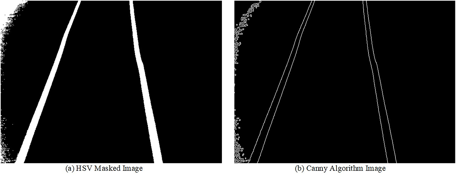
Figure 6: Edge detection process with canny algorithm
In autonomous driving systems, defining a ROI in an image is critical for accurately calculating the steering angle. This process allows focusing on a specific area that is meaningful for analysis rather than processing the entire image, thus reducing processing time and increasing system efficiency. In this study, we focused on a specific region to ensure the vehicle navigates on the road without contacting lane markings. This analysis region in the image is defined as a rectangular area representing a specific portion of the road surface. This approach allows only the portion containing structural information of the road to be evaluated during the steering angle calculation process, resulting in more accurate and more stable steering results. In this context, Fig. 7a shows the road image processed with the Canny edge detection algorithm. Fig. 7b represents the region selected as the ROI in this image. This region, obtained through the ROI definition, allows the system to evaluate only the portion containing the road lanes. Finally, Fig. 7c presents the masked image created for use in steering angle calculations. This image was processed to include only the edge information within the ROI and made suitable for analysis.
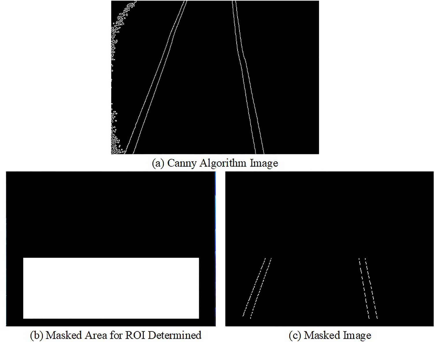
Figure 7: Process of ROI determination
The Hough transform is a mathematical approach widely used in computer vision and image processing to detect basic geometric shapes such as lines, circles, and ellipses. The fundamental principle of this method is to transform potential shapes in the image space into a parameter space containing the parameters that define these shapes. Thus, even missing, noisy, or distorted shapes in the image can be represented more regularly and clearly within this parameter space. The Hough transform stands out as a powerful tool, especially in scenarios where traditional methods, such as edge detection, fail. This method enables the successful detection of shapes even with missing, broken, or distorted edges, providing a high level of robustness in image processing. By representing pixels in an image in a parameter space, the Hough transform enables the detection of relevant geometric structure. Thus, a shape that cannot be directly identified in the image space can emerge as a distinct pattern in the parameter space [83]. Fig. 8a presents the original image captured by the camera, while Fig. 8b shows an image of lines within the relevant area using the Hough Line transform.
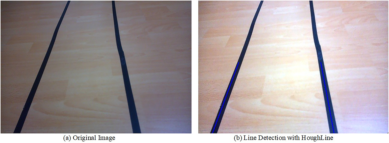
Figure 8: Line detection process with HoughLine algorithm
3.2.5 Determination of Road Boundaries and Local Path Planning
Following the lane detection process, the identification of left and right lane boundaries provides the foundation for local path generation. By using these lane markings, the system estimates an appropriate steering trajectory that enables the autonomous vehicle to navigate within safe boundaries and maintain its course. The steering angle is dynamically adjusted based on the detected lane geometry, ensuring both lane centering and reliable navigation along the planned path. Detecting road lane markings primarily takes into account the slopes of the lines and their intersections with the axes. A linear line is mathematically expressed as y = mx + c. Here, m represents the slope, and c represents the point where the line intersects the y-axis. A more stable line representation is achieved by averaging the slope and intersection points of the line segments detected using the Hough Transform. Left lane markings in an image generally have a negative slope. For example, if a line segment satisfies the conditions x1 < x2 and y2 < y1, then the slope is calculated with the formula (y2 − y1)/(x2 − x1), and this value is negative. Therefore, lines with a negative slope are assigned to the left lane; Lines with positive slope are classified as belonging to the right lane. Vertical lines with infinite slope appear when x1 = x2. Such lines are excluded from the analysis to prevent errors in calculations. To increase detection accuracy, each image frame is divided into two regions, right and left, using two boundary lines. All x-axis points to the right of the right boundary line are included in the right lane calculation, while x-axis points to the left of the left boundary line are used in the left lane calculation. An example visual classification process for this method is shown in Fig. 9. In this image, the left and right lane distinction based on line slopes is graphically presented.
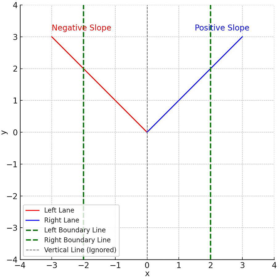
Figure 9: Detection of left and right lanes
After the right and left lane markings are identified, a reference line is created exactly midway between these two lines. This reference line dynamically tracks the movements of the right and left lines and can change direction parallel to the lines’ orientation. This line is called a direction line. The direction line is positioned at the midpoint of the x-axis in the image and generates an angle to determine the vehicle’s orientation. The resulting angle is the angle the direction line makes with the vertical axis. When this angle is 90∘, the vehicle is moving linearly, that is, in a straight line. When the angle value falls below 90∘, the direction line is turned left; when it exceeds 90∘, it is turned right. Therefore, if the direction line has an angle below 90∘, the vehicle will turn left, and if it exceeds 90∘, it will turn right. This approach plays a critical role in determining orientation in control algorithms that aim to keep the vehicle’s position central between lanes. Fig. 10a presents an example direction line, while Fig. 10b presents the corresponding steering angle calculation.
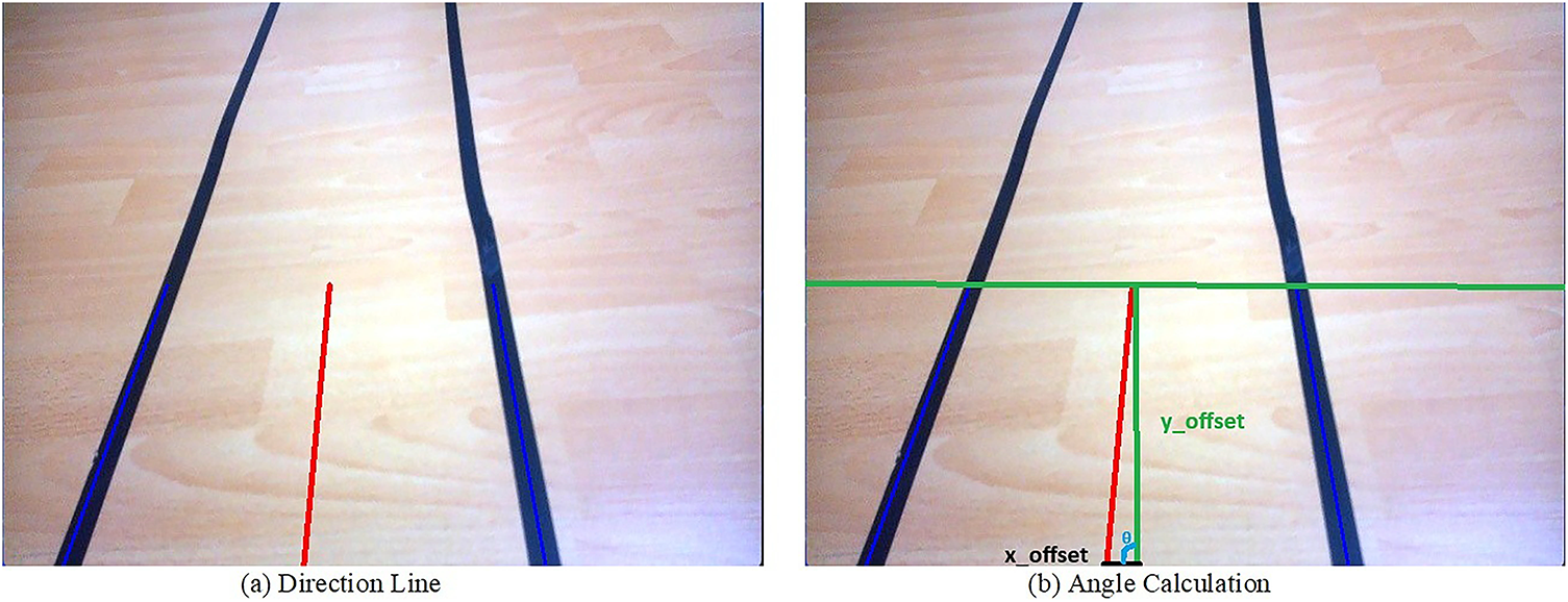
Figure 10: Road boundaries determination and steering angle calculation
After the direction line is generated, its slope relative to the horizontal plane (i.e., the x-axis) and the point where it intersects the y-axis (intersection) are calculated. These parameters are the fundamental components that provide information about the vehicle’s orientation. When the image processing algorithm successfully detects two road lines, one on the right and one on the left, the direction angle is calculated based on the center line created by averaging these two lines. This method provides more accurate steering to ensure the vehicle remains centered. However, when only a single line is detected, the system generates an estimated direction line based on the current line and generates a direction angle based on this line. This approach allows the vehicle to continue on course without deviating from the route in cases of missing data. Fig. 11 shows a visual representation of the steering angle generated based on direction lines.

Figure 11: Generating angles based on direction line
After detecting road markings, the x_offset value is calculated, which represents the positional difference between the vehicle’s current position and the lane center. This value numerically indicates how far the vehicle has drifted to the right or left relative to the lane center. According to Fig. 10, if a double line is detected on the road [84,85]:
According to Fig. 10, if a single line is detected on the road [84,85]:
Once the x_offset value is determined, the steering angle required to correct the vehicle’s direction is calculated. This angle is typically obtained through a trigonometry-based calculation using a directional line at a fixed distance from where the vehicle is moving forward. This allows the system to steer the vehicle to align with the center of the lane. This calculation is critical for the vehicle’s stable and safe progress on the road.
3.3 Traffic Sign Recognition with YOLOv8
YOLO is a real time object detection algorithm based on Convolutional Neural Network (CNN) architecture of deep learning. Instead of using a multi-stage pipeline, YOLO divides an input image into a grid and simultaneously predicts bounding boxes, confidence scores, and class probabilities for each grid cell [86]. This unified approach allows the algorithm to process images much faster than previous methods, making it highly suitable for real-time applications such as autonomous driving and video surveillance. The core strength of YOLO lies in its ability to see the entire image at once, which helps it to learn contextual information and significantly reduce false-positive detections. The basic YOLO network structure is shown in Fig. 12 [87].
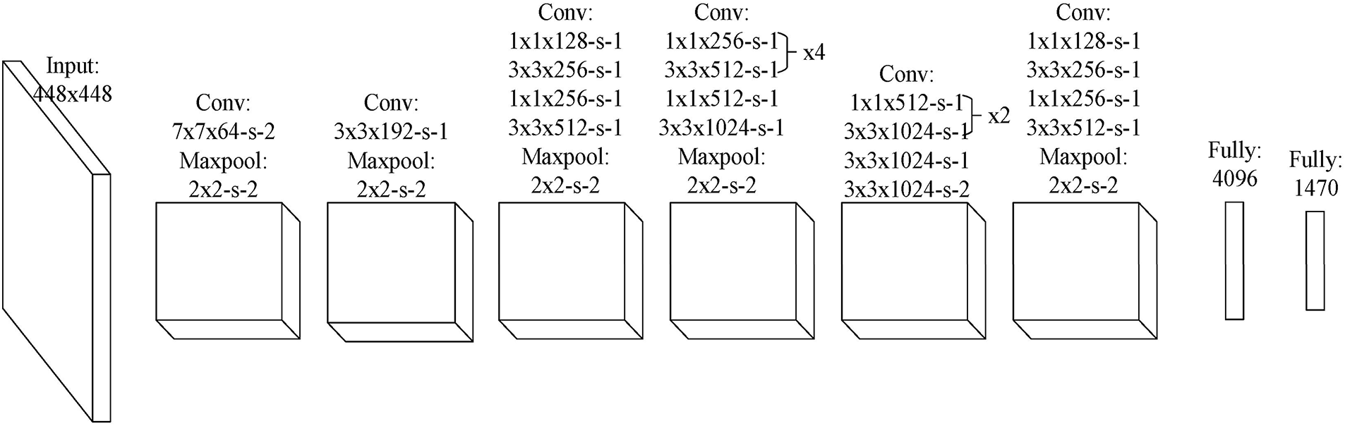
Figure 12: The basic YOLO network structure [87]
YOLOv8 distinguishes itself from previous versions with significant architectural and functional improvements. Its core superiority lies in the adoption of a modern, anchor-free head, which simplifies the training process and eliminates the need for manually setting anchor box parameters [88]. The model also features a more efficient backbone and neck, leading to enhanced performance with higher mean Average Precision (mAP) and faster inference speeds [88]. Furthermore, YOLOv8 expands beyond traditional object detection, offering capabilities for instance segmentation and pose estimation within a unified framework. This versatility, combined with its refined architecture and a more user-friendly API, makes it a powerful and flexible choice for a wide range of computer vision tasks [89]. YOLO reframes object detection as a single regression problem, directly predicting bounding boxes and class probabilities from full images. The core of its mathematical formulation is the loss function, which is a weighted sum of three components: classification loss, localization loss, and confidence loss [90]. YOLO is a real-time object detection algorithm that frames the task as a single regression problem. The core of its mathematical formulation is the loss function, which is a weighted sum of three main components: localization loss, confidence loss, and classification loss. This unified approach allows the model to predict bounding boxes and class probabilities simultaneously. The total loss function is defined as follows [91–93]:
The parameters and components in Eq. 10 are explained as follow [91–93]:
•
• B: The number of bounding boxes that each grid cell is configured to predict.
•
•
•
•
•
•
•
•
•
•
The loss function is designed to heavily penalize localization and classification errors in cells that contain objects, while giving less weight to confidence errors in empty grid cells. This ensures the model learns to both accurately find and identify objects in a single forward pass.
In this prototype study, 4 classes that are red, yellow, green (for traffic lights) and stop traffic sign have been created by using YOLOv8. 800 images are labelled for each class and each labelled class has been prepared by data.yaml file. At the end of the training process, a trained model file (best.pt) based on 4 classes is obtained for the prototype study. Due to the memory limitation of the prototype autonomous vehicle, the trained model file was converted to tflite format. In this way, the trained model based on YoloV8 could be used lack of the memory limitation for the study. The experimental results of the traffic sign detection have been explained in Section 4.3 detailed.
3.4 Sensor Fusion and Decision Algorithm
The decision-making algorithm integrates visual and ultrasonic sensor data using a rule-based fusion approach. To enhance system reliability and safety, the proposed prototype integrates camera-based visual perception with ultrasonic distance sensing in a unified decision framework. The Raspberry Pi module performs lane detection and traffic sign recognition—specifically identifying “red,” “green,” “yellow,” and “stop” classes—and communicates both steering angle adjustments and detected object labels (e.g., stop, red) to the Arduino Nano. Concurrently, the Arduino continuously acquires distance readings from three ultrasonic sensors positioned at the front of the vehicle. Ultrasonic distance readings are sampled at 10 Hz and compared against predefined safety thresholds (e.g., <30 cm for immediate obstacle detection). The decision-making mechanism prioritizes safety through a hierarchical rule set: if any ultrasonic sensor measures a distance shorter than 30 cm or the vision module detects a “stop” sign or “red” light, the vehicle halts immediately; otherwise, it proceeds at the predefined speed. In conflicting scenarios, safety conditions always take precedence over navigation commands. To mitigate sensor noise and measurement inconsistencies, a majority voting algorithm combined with a three-sample averaging technique is employed, filtering out spurious echoes and preventing unnecessary stops. This multi-sensor fusion approach ensures robust obstacle avoidance and enhances the overall reliability of autonomous decision-making under real-world conditions.
4 Application and Experimental Results
The autonomous vehicle system developed in this study was experimentally validated on a test track designed to emulate real-world road conditions, with a particular focus on navigation and path planning performance. The prototype integrates a Raspberry Pi, an Arduino Nano, a camera module, ultrasonic sensors, motor drivers, and the vehicle chassis to form a complete embedded framework. During the evaluation, multiple navigation-related functions were tested, including lane-based path following, steering trajectory estimation accuracy, obstacle-aware path adjustment, traffic sign recognition for navigation decisions, and reliable data communication between the control boards. A schematic of the experimental studies conducted within the application is presented in Fig. 13.
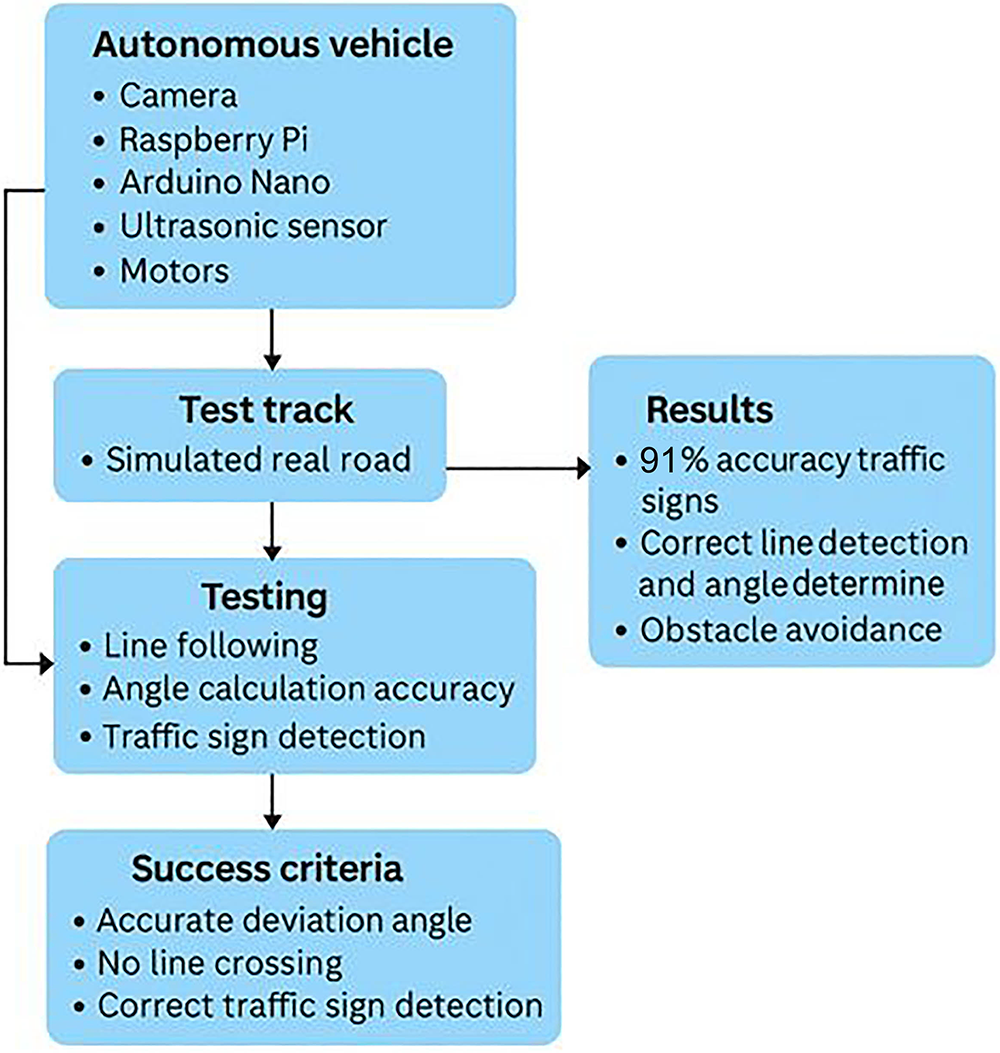
Figure 13: Implementation and experimental results scheme
During line tracking, road lines were detected using the Hough transform from the camera image, the midline between these lines was determined, and the vehicle’s lateral position was continuously updated. The deviation angle obtained from this axis represents the angular difference between the vehicle’s current direction and the centerline of the road. It is calculated instantly by the system and transferred to the steering control. Obtaining the correct deviation angle value allowed the vehicle to proceed without contacting the lines. Furthermore, ultrasonic sensors placed at the front of the vehicle detected obstacles, and speed control and stop commands were successfully implemented based on distance. The system’s accuracy was evaluated by the reliability of the deviation angle, the absence of lane violations, the speed of obstacle response, and the success of traffic sign recognition. All criteria were successfully met. Serial communication between the Raspberry Pi and Arduino Nano eliminated any delays in decision-making and action execution. The YOLOv8 object recognition algorithm was used to identify traffic signs. The developed system identified different traffic signs with 91% accuracy and generated appropriate decisions accordingly. Thus, the autonomous vehicle increased environmental awareness by perceiving traffic rules through visual data.
4.1 Development of Autonomous Vehicle Prototype
During the autonomous vehicle design process, a custom vehicle chassis was designed using three-dimensional (3D) modeling to meet the study’s objectives and requirements, with a flexible structure and the ability to accommodate all hardware components. A suspension system was integrated with red wheels to enhance the vehicle’s stability and handling. Dedicated compartments for electronic components ensure a streamlined mounting structure and wiring infrastructure. This design also facilitates the integration of various sensors and control units, aiming to enhance the overall functionality of the system. Fig. 14 presents 3D images of the vehicle chassis.
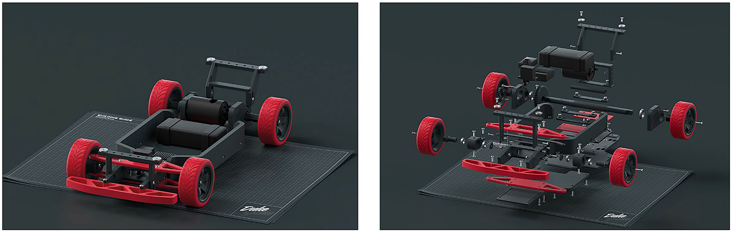
Figure 14: 3D model of autonomous vehicle
Following the completion of the vehicle design, the production and assembly phases began. PLA+, a material that offers structural strength and lightweight advantages, was chosen for the production process. During the assembly phase, all components in the system were carefully assembled, creating the final vehicle structure. A special add-on for the camera module, which can be integrated into the chassis later, was designed and installed. Fig. 15 shows final images of the autonomous vehicle.
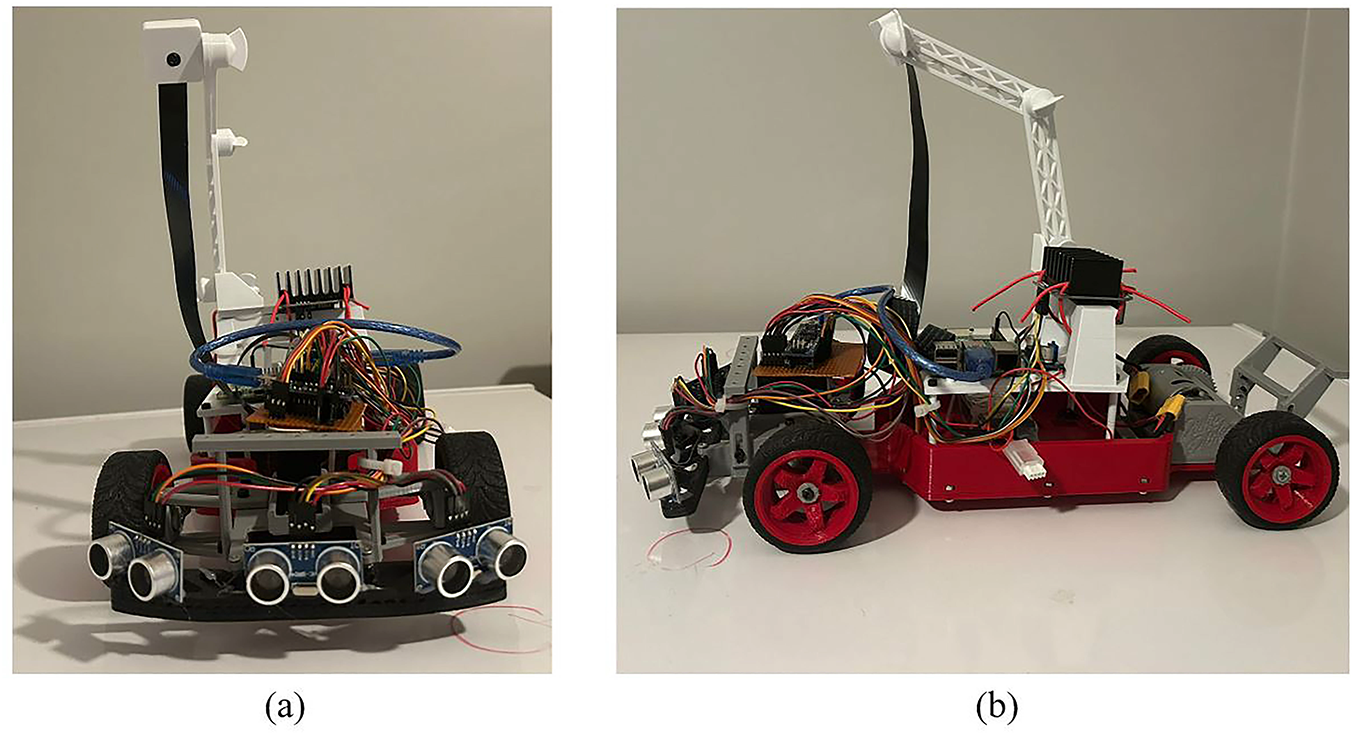
Figure 15: RC vehicle appearance (a) front view (b) side view
Following the completion of the vehicle design and fabrication processes, lane detection was implemented as the core component of the local path planning and navigation system. To evaluate this capability, a controlled test track was constructed to replicate real-world road conditions, including appropriate surface materials, lane markings, and curved sections. This environment allowed for a comprehensive assessment of the vehicle’s path-following accuracy, navigation stability, and real-time correction performance. The lane detection module operated using vision-based image processing techniques. Continuous image frames captured from the onboard camera were processed through a series of operations involving filtering, edge detection, and Hough line transformation to extract lane boundaries. The system then computed the median axis between the detected boundaries to determine the vehicle’s orientation and deviation angle relative to the target path. These parameters were continuously transmitted to the steering control module, enabling dynamic and precise trajectory adjustments. As a result, the vehicle successfully maintained a stable trajectory within lane boundaries throughout the tests, exhibiting consistent and reliable navigation performance under varying lighting and surface conditions.
For lane and edge detection, the input frames were first converted from RGB to HSV color space to isolate lane markings more robustly under variable lighting. The lower and upper HSV threshold values were set to [0, 0, 0] and [179, 255, 87], respectively, which provided the most stable segmentation results during experimental calibration. The Canny edge detection used Gaussian smoothing with a (5
Fig. 16a shows the artificial lane markings created in the test environment, and the test setup designed to evaluate the system’s accuracy is detailed. Fig. 16b shows the image processing results of an image obtained from the vehicle’s camera while the vehicle was in motion; it is observed that the lane markings were detected and the area of interest in the image was successfully determined. Fig. 16c,d shows images of the vehicle’s lane tracking operation while in motion. These images detail the directional corrections made by the vehicle in line with the detected lines and the maneuvers performed to maintain the steering angle while aligning with the centerline. These results demonstrate that the developed system achieves the required precision for line tracking and, in particular, successfully performs directional correction capabilities through snapshot processing.
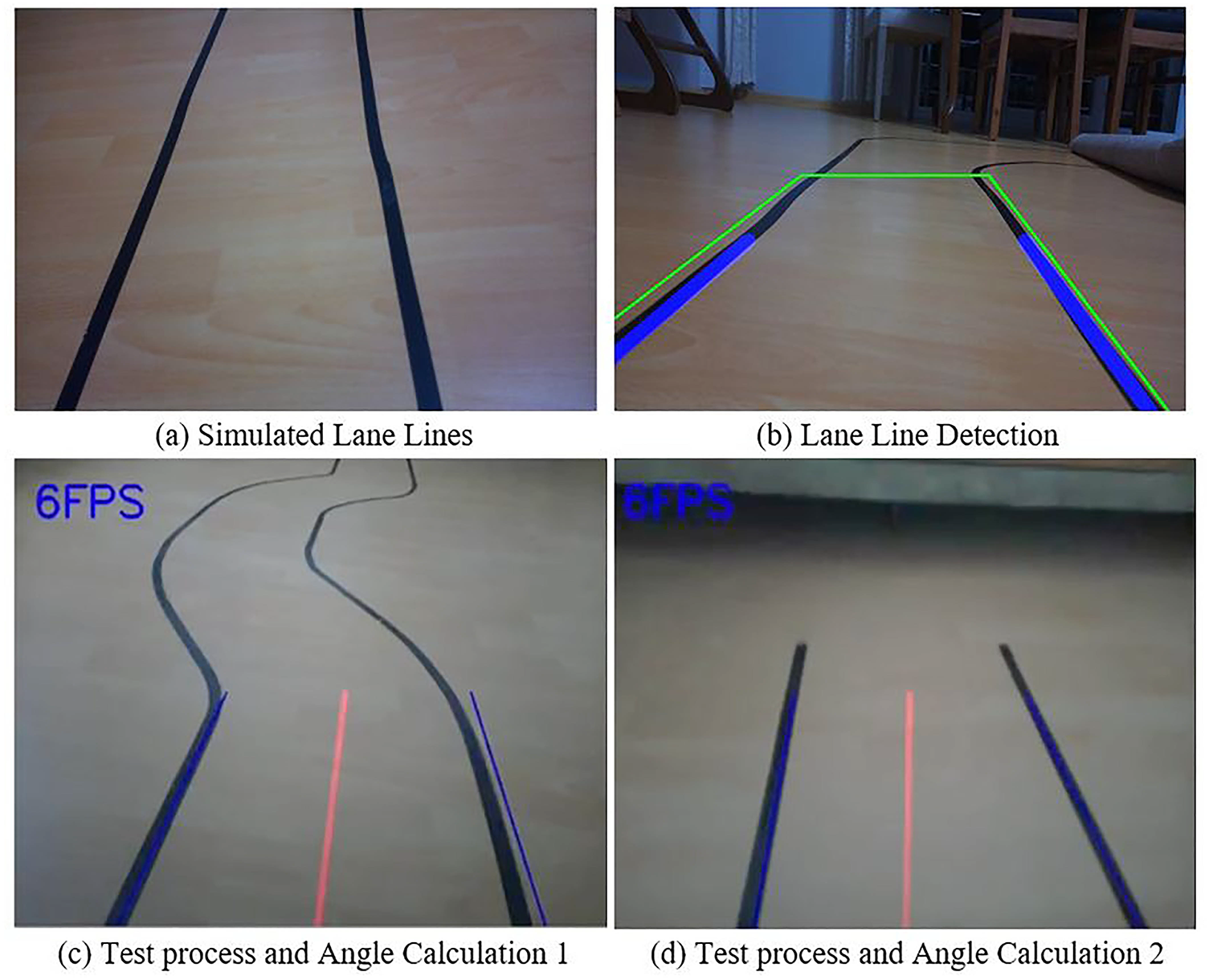
Figure 16: Lane line detection with autonomous vehicle
4.3 Detection of Traffic Signs
Following the successful detection of lane markings, testing was conducted to identify traffic signs, another critical component of the system. In this phase, the YOLOv8 algorithm, which boasts high accuracy rates in object recognition and classification, was utilized. In this phase, the YOLOv8 algorithm renowned for its high accuracy in object recognition and classification was employed. YOLOv8 was chosen for its optimal trade-off between detection accuracy, inference speed, and model size, making it particularly well-suited for deployment on resource-constrained embedded platforms such as the Raspberry Pi. Its lightweight and quantization-friendly architecture enables competitive detection performance and real-time processing while maintaining satisfactory frame rates and energy efficiency. Compared to earlier YOLO versions, YOLOv8 demonstrates enhanced feature extraction capabilities and superior computational efficiency, aligning well with the objective of developing a cost-effective embedded autonomous system. In the implemented design, a custom-trained deep learning model based on the YOLOv8 architecture was developed for traffic sign detection and evaluated under various real-world scenarios.
In the traffic sign detection process, the YOLOv8 model was trained for 25 epochs with an input size of 224
The model training process was conducted on a local computer equipped with an NVIDIA RTX 3070 GPU (8 GB), an AMD Ryzen 5 5500 CPU, 16 GB of Kingston DDR4 RAM (3200 MHz), and a Kingston 1 TB NV2 2280 NVMe SSD. This hardware configuration provided adequate computational performance and memory bandwidth for real-time image processing, CNN training, and validation tasks, enabling stable and efficient model convergence.
The tests employed four basic traffic sign classes: Red Light, Yellow-Orange Light, Green Light, and Stop Sign. Images captured by the vehicle’s on-board camera were processed in real time by the YOLOv8 model, and each of the traffic signs in scenarios was successfully detected. The system is capable of executing commands such as stopping, waiting, or proceeding by activating appropriate decision mechanisms based on these signs. Fig. 17 shows images from the test process and includes sample images of the system’s identification of traffic signs. Additionally, the YoloV8 performance metrics have been shown in Table 3. The results demonstrate that the model operates with high accuracy and reliably performs traffic sign recognition tasks.
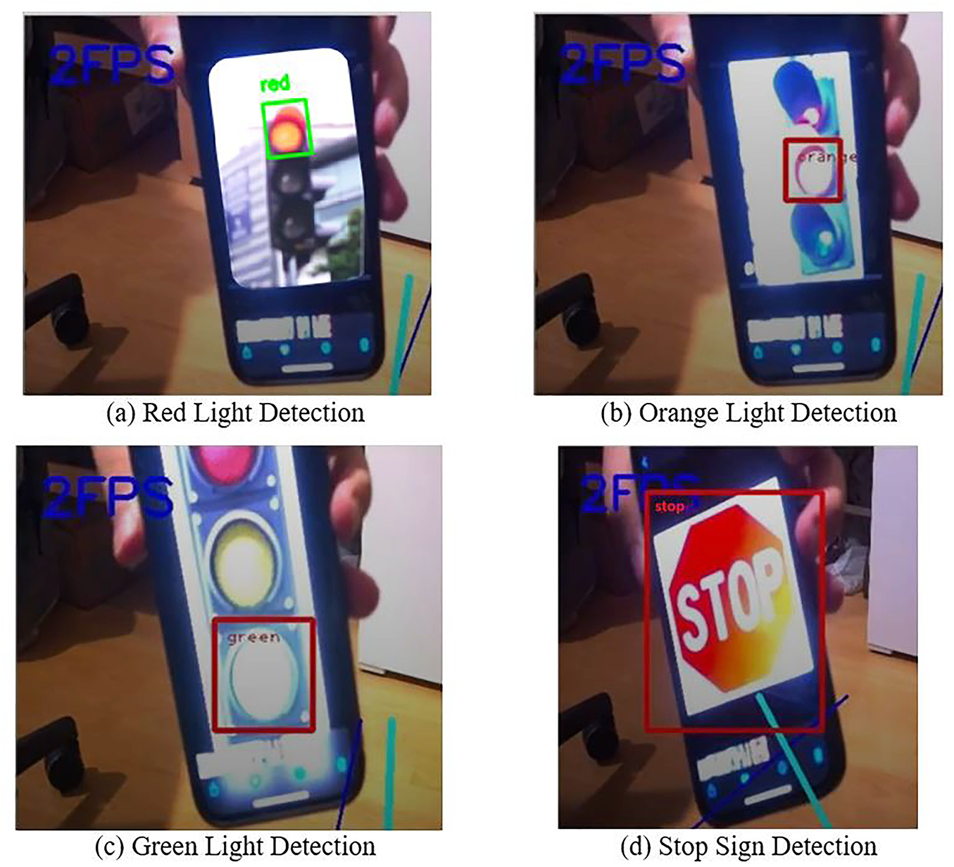
Figure 17: Detection of traffic signs

In this study, a mini autonomous vehicle prototype capable of performing basic autonomous driving functions such as camera-based line tracking, traffic sign detection, and obstacle detection was developed. Thanks to the integration of real-time image processing techniques and embedded systems, high-accuracy results were achieved using low-cost hardware. The developed autonomous vehicle prototype was experimentally validated in a controlled indoor environment to evaluate lane-following stability, obstacle avoidance reliability, and visual recognition performance. The test track measured 3 m in length and 30 cm in lane width, with a flat parquet surface to ensure repeatable conditions. Two lighting scenarios were considered: daylight (about 750 lux) and low-light illumination. The onboard Raspberry Pi 4 (8 GB RAM) executed real-time vision processing at an average of 6 frames per second (FPS), while vehicle speed was maintained at 0.8 m/s using PWM-based motor control.
A total of 20 autonomous driving trials were conducted. A trial was deemed unsuccessful if the vehicle (i) deviated entirely from the lane, (ii) failed to stop upon obstacle detection, or (iii) misinterpreted a visual cue. Out of all runs, 19 were completed successfully, yielding a 95% overall success rate. The average lane deviation relative to the visual centerline was
From a control perspective, the lane-tracking algorithm—based on Canny edge detection and Hough line transformation—maintained a maximum steering angle deviation of
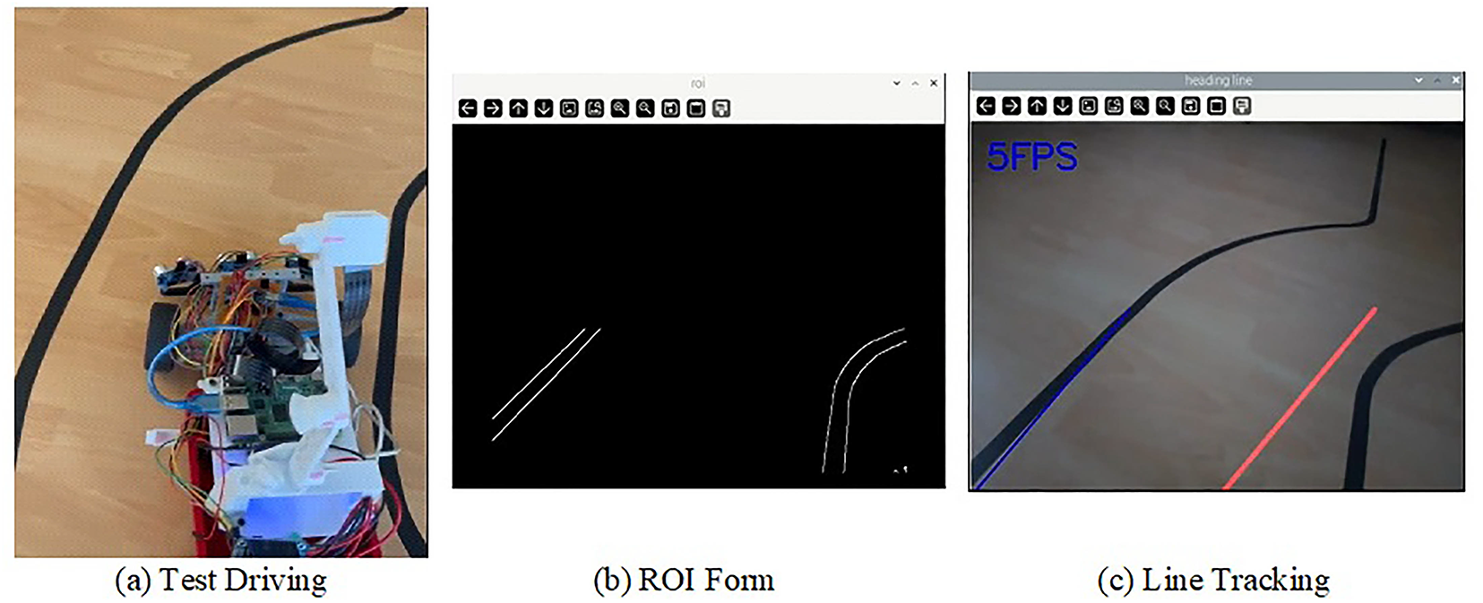
Figure 18: Autonomous vehicle test drive 1
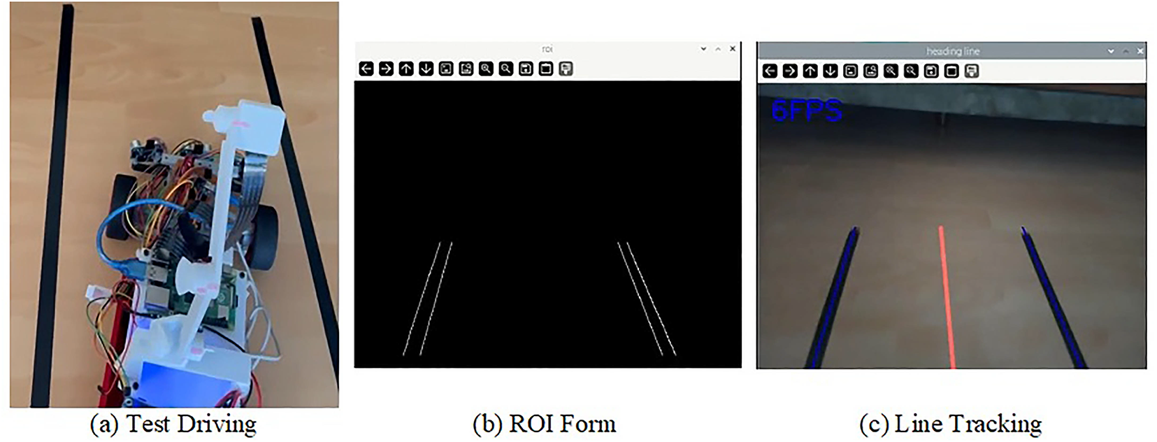
Figure 19: Autonomous vehicle test drive 2
The following results were drawn within the scope of the test studies.
1. In the line-tracking experiments, lane markings were accurately detected using filtering, thresholding, and edge detection on images captured by the onboard camera. The deviation from the desired trajectory was then calculated, allowing continuous steering adjustments to align the vehicle with the lane center and follow the planned path. Experimental results demonstrated stable navigation performance across varying road geometries. However, limitations arose due to the prototype’s physical constraints. In sharp curves or sudden direction changes, the vehicle’s limited turning radius occasionally caused it to cross lane boundaries, indicating that structural factors such as body design and wheelbase significantly affect maneuverability and path-following accuracy. These findings suggest that further refinements to the 3D prototype design are necessary to enhance navigation capabilities and ensure robust performance under diverse driving conditions.
2. The YOLOv8 model used for traffic sign detection was optimized with a customized training dataset, achieving a recognition accuracy of up to 91% in experimental navigation tests. These results demonstrate the effectiveness of deep learning-based perception modules, even when using low-resolution cameras, in supporting navigation and path planning. However, challenges such as varying illumination, motion blur, and partial occlusion occasionally led to misclassifications. Enhancing system robustness and ensuring more reliable guidance will require retraining with a larger and more diverse dataset.
3. Communication between the Arduino Nano and Raspberry Pi was reliable, enabling real-time transmission of control commands and synchronized execution across the embedded hardware. This integration demonstrates the system’s capability to support real-time navigation and path planning. The ultrasonic sensors used for obstacle detection consistently identified short-range obstacles, allowing the vehicle to adjust its trajectory accordingly. However, at higher speeds, reduced stopping distances highlight the need for faster-reacting sensor technologies to further enhance obstacle-aware navigation and ensure safe path planning.
4. The YOLOv8-based object recognition algorithm for traffic sign detection can achieve high frame rates on powerful hardware. However, the limited processing power and memory of the Raspberry Pi 4 constrained real-time performance, requiring the system to operate at lower FPS. This led to detection delays and, in some cases, missed traffic signs. These results indicate that autonomous driving systems demanding fast, real-time decisions would benefit from higher-performance hardware, such as the NVIDIA Jetson Nano, Jetson Xavier NX, or similar AI accelerators, to enhance detection speed and overall system reliability.
As a result, this study has demonstrated the feasibility of developing a low-cost, portable, and functional autonomous vehicle prototype. The findings serve as a reference for the development of similar systems for educational and research purposes. In the current version of the system, several limitations have been identified, particularly related to reduce robustness of YOLOv8 detection performance under varying illumination and environmental conditions. In future work, plans to implement short-term improvements focusing on improving detection stability and computational efficiency. These include applying model pruning and quantization to improve real-time performance on Raspberry Pi 4 without compromising accuracy, integrating adaptive HSV thresholding for lane detection in low-light conditions, and expanding the dataset to include images captured under diverse weather and lighting scenarios. Additionally, the ultrasonic obstacle detection module will be optimized through temporal filtering and confidence-based fusion with visual perception data to increase reliability in dynamic environments. These planned improvements are expected to enhance both the robustness and scalability of the proposed autonomous vehicle prototype.
In this study, a low-cost and energy-efficient autonomous vehicle prototype was developed using an integrated embedded system based on Raspberry Pi 4 and Arduino Nano, successfully demonstrating real-time lane-based path planning, navigation, and traffic sign recognition. Lane geometry was extracted through image processing techniques implemented in Python and OpenCV, while the steering angle was calculated using Canny edge detection and Hough Transform to maintain navigation within lane boundaries. This navigation information was transmitted to the Arduino Nano via serial communication, where servo and DC motor control were carried out through the L298N driver module to execute trajectory adjustments. For traffic sign detection, a YOLOv8-based deep learning model achieved high recognition accuracies (87%–91%) for critical signs such as red light, yellow light, green light, and stop signs, providing essential inputs for navigation decision-making. The lane-tracking algorithm achieved a 95% success rate under well-lit conditions. Moreover, distance measurements from HC-SR04 ultrasonic sensors were integrated with visual perception outputs to support obstacle detection and dynamic path adjustment for collision avoidance. From a hardware integration perspective, the processing capability of the Raspberry Pi worked in harmony with the low-level control functions of the Arduino Nano, enabling synchronized execution of perception, path planning, and navigation control in real time. The experimental results confirm that the proposed system can successfully perform fundamental autonomous driving tasks and serve as a practical prototype platform for education and research in intelligent transportation and embedded navigation systems.
Beyond the presented experimental results, this study provides valuable insights for deploying deep learning-based vision systems on resource-constrained embedded platforms. The experience gained from developing the YOLOv8-based traffic sign recognition and lane detection framework demonstrates the importance of balancing model complexity, inference speed, and energy consumption when implementing real-time computer vision on devices such as the Raspberry Pi 4. Furthermore, the modular hardware-software architecture adopted in this research can be adapted to other applications, including low-cost delivery robots, intelligent surveillance units, or smart mobility systems. The findings highlight the broader applicability of lightweight vision-based perception frameworks in various real-world embedded scenarios beyond autonomous driving.
In future studies, several enhancements are envisioned to extend the system’s functionality and robustness. First, the integration of deep learning–based segmentation techniques is planned to enhance lane detection accuracy, particularly under low-light conditions. In addition, to address more complex real-world scenarios such as curved lane structures, varying illumination, and partial occlusions, approaches based on adaptive filtering and CNN-based lane detection will be discussed instead of traditional Hough Transform implementations. Advanced driving control strategies, such as those based on Proportional–Integral–Derivative (PID) control or fuzzy logic, will be implemented to achieve smoother and more adaptive vehicle maneuvering. Furthermore, the incorporation of Global Positioning System (GPS) and Inertial Measurement Unit (IMU) modules will enable precise real-time position and orientation tracking.
Acknowledgement: During the preparation of this manuscript, the authors used Grammarly and ChatGPT 4.0 tools in order to only improve language and readability. After using these tools, the authors have carefully reviewed and revised the content and accept full responsibility for all content.
Funding Statement: This research received no external funding.
Author Contributions: Conceptualization, Hakan Üçgün and Onur Ali Korkmaz; methodology, Onur Ali Korkmaz and Hakan Üçgün; software, Onur Ali Korkmaz and Rıdvan Yayla; validation, Onur Ali Korkmaz, Hakan Üçgün and Rıdvan Yayla; formal analysis, Hakan Üçgün and Rıdvan Yayla; investigation, Onur Ali Korkmaz, Hakan Üçgün and Rıdvan Yayla; resources, Hakan Üçgün and Rıdvan Yayla; data curation, Hakan Üçgün; writing—original draft preparation, Hakan Üçgün and Rıdvan Yayla; writing—review and editing, Hakan Üçgün and Rıdvan Yayla; visualization, Hakan Üçgün; supervision, Rıdvan Yayla. All authors reviewed the results and approved the final version of the manuscript.
Availability of Data and Materials: Data available on request from the authors.
Ethics Approval: Not applicable.
Conflicts of Interest: The authors declare no conflicts of interest to report regarding the present study.
References
1. Yun K, Yun H, Lee S, Oh J, Kim M, Lim M, et al. A study on machine learning-enhanced roadside unit-based detection of abnormal driving in autonomous vehicles. Electronics. 2024;13(2):288. doi:10.3390/electronics13020288. [Google Scholar] [CrossRef]
2. Reda M, Onsy A, Haikal AY, Ghanbari A. Path planning algorithms in the autonomous driving system: a comprehensive review. Robot Auton Syst. 2024;174(10):104630. doi:10.1016/j.robot.2024.104630. [Google Scholar] [CrossRef]
3. Zablocki É, Ben-Younes H, Pérez P, Cord M. Explainability of deep vision-based autonomous driving systems: review and challenges. Int J Comput Vis. 2022;130(10):2425–52. doi:10.1007/s11263-022-01657-x. [Google Scholar] [CrossRef]
4. Padmaja B, Moorthy CHV, Venkateswarulu N, Bala MM. Exploration of issues, challenges and latest developments in autonomous cars. J Big Data. 2023;10(1):61. doi:10.1186/s40537-023-00701-y. [Google Scholar] [CrossRef]
5. Ni J, Chen Y, Chen Y, Zhu J, Ali D, Cao W. A survey on theories and applications for self-driving cars based on deep learning methods. Appl Sci. 2020;10(8):2749. doi:10.3390/app10082749. [Google Scholar] [CrossRef]
6. Sinha A, Macaluso A, Klusch M. Nav-Q: quantum deep reinforcement learning for collision-free navigation of self-driving cars. Quant Mach Intell. 2025;7(1):19. doi:10.1007/s42484-024-00226-4. [Google Scholar] [CrossRef]
7. Odey N, Marhoon A. A novel deep learning object detection based on PCA features for self driving cars. Iraqi J Elect Electr Eng. 2025;21(2):186–95. doi:10.37917/ijeee.21.2.18. [Google Scholar] [CrossRef]
8. Li J, Xie Y, Huo Y. An independent suspension and trafficability analysis for an unmanned ground platform. Symmetry. 2025;17(1):128. doi:10.3390/sym17010128. [Google Scholar] [CrossRef]
9. Tang C, Peng T, Xie X, Peng J. 3D path planning of unmanned ground vehicles based on improved DDQN. J Supercomput. 2025;81(1):276. doi:10.1007/s11227-024-06690-w. [Google Scholar] [CrossRef]
10. Fan Q, Li Y, Deveci M, Zhong K, Kadry S. LUD-YOLO: a novel lightweight object detection network for unmanned aerial vehicle. Inf Sci. 2025;686:121366. doi:10.1016/j.ins.2024.121366. [Google Scholar] [CrossRef]
11. Pandey BK, Pandey D, Sahani SK. Autopilot control unmanned aerial vehicle system for sewage defect detection using deep learning. Eng Rep. 2025;7(1):e12852. doi:10.1002/eng2.12852. [Google Scholar] [CrossRef]
12. Zhang H, Zhu J, Xie W, Huang K, Wu M, Lu C, et al. Fusion of computer vision and piezoelectric tactility approach to measuring moving vehicle loads. Measurement. 2025;240:115616. doi:10.1016/j.measurement.2024.115616. [Google Scholar] [CrossRef]
13. Opanasenko VM, Fazilov SK, Radjabov SS, Kakharov SS. Multilevel face recognition system. Cybern Syst Anal. 2024;60(1):146–51. doi:10.1007/s10559-024-00655-w. [Google Scholar] [CrossRef]
14. Guo R, Guo H, Wang L, Chen M, Yang D, Li B. Development and application of emotion recognition technology—a systematic literature review. BMC Psychol. 2024;12(1):95. doi:10.1186/s40359-024-01581-4. [Google Scholar] [PubMed] [CrossRef]
15. Shamshiri A, Ryu KR, Park JY. Text mining and natural language processing in construction. Autom Constr. 2024;158:105200. doi:10.1016/j.autcon.2023.105200. [Google Scholar] [CrossRef]
16. Gheorghe C, Duguleana M, Boboc RG, Postelnicu CC. Analyzing real-time object detection with YOLO algorithm in automotive applications: a review. Comput Model Eng Sci. 2024;141(3):1939–81. doi:10.32604/cmes.2024.054735. [Google Scholar] [CrossRef]
17. Grigorescu S, Trasnea B, Cocias T, Macesanu G. A survey of deep learning techniques for autonomous driving. J Field Robot. 2020;37(3):362–86. doi:10.1002/rob.21918. [Google Scholar] [CrossRef]
18. Clements LM, Kockelman KM. Economic effects of automated vehicles. Transportat Res Record. 2017;2606(1):106–14. doi:10.3141/2606-14. [Google Scholar] [CrossRef]
19. Soylu E, Soylu T. A performance comparison of YOLOv8 models for traffic sign detection in the Robotaxi-full scale autonomous vehicle competition. Multim Tools Applicat. 2024;83(8):25005–35. doi:10.1007/s11042-023-16451-1. [Google Scholar] [CrossRef]
20. Li G, Liu C, Wu L, Xiao W. A mixing algorithm of ACO and ABC for solving path planning of mobile robot. Appl Soft Comput. 2023;148(15):110868. doi:10.1016/j.asoc.2023.110868. [Google Scholar] [CrossRef]
21. Shoeb M, Ali MA, Shadeel M, Bari DMA. Self-driving car: using Opencv2 and machine learning. Int J Analyt Experim Modal Anal (IJAEMA). 2022;14(5):325–30. [Google Scholar]
22. Caleffi F, da Silva Rodrigues L, da Silva Stamboroski J, Pereira BM. Small-scale self-driving cars: a systematic literature review. J Traffic Transport Eng (English Edition). 2024;11(2):271–92. doi:10.1016/j.jtte.2023.09.005. [Google Scholar] [CrossRef]
23. Olayode IO, Du B, Severino A, Campisi T, Alex FJ. Systematic literature review on the applications, impacts, and public perceptions of autonomous vehicles in road transportation system. J Traffic Transport Eng (English Edition). 2023;10(6):1037–60. doi:10.1016/j.jtte.2023.07.006. [Google Scholar] [CrossRef]
24. Dhaif ZS, El Abbadi NK. A review of machine learning techniques utilised in self-driving cars. Iraqi J Comput Sci Mathem. 2024;5(1):1. doi:10.52866/ijcsm.2024.05.01.015. [Google Scholar] [CrossRef]
25. Karkera T, Singh C. Autonomous bot using machine learning and computer vision. SN Comput Sci. 2021;2(4):251. doi:10.1007/s42979-021-00640-6. [Google Scholar] [CrossRef]
26. Seo P, Kim H, Kim KH. Driver fatigue recognition using limited amount of individual electroencephalogram. Biomed Eng Lett. 2025;15(1):143–57. doi:10.1007/s13534-024-00431-x. [Google Scholar] [PubMed] [CrossRef]
27. Jang SW, Ahn B. Implementation of detection system for drowsy driving prevention using image recognition and IoT. Sustainability. 2020;12(7):3037. doi:10.3390/su12073037. [Google Scholar] [CrossRef]
28. Waykole S, Shiwakoti N, Stasinopoulos P. Review on lane detection and tracking algorithms of advanced driver assistance system. Sustainability. 2021;13(20):11417. doi:10.3390/su132011417. [Google Scholar] [CrossRef]
29. Hariyono J, Jo KH. Detection of pedestrian crossing road: a study on pedestrian pose recognition. Neurocomputing. 2017;234(4):144–53. doi:10.1016/j.neucom.2016.12.050. [Google Scholar] [CrossRef]
30. Sulistyowati R, Suryowinoto A, Sujono HA, Iswahyudi I. Monitoring of road damage detection systems using image processing methods and Google Map. In: IOP Conference Series: Materials Science and Engineering. Vol. 1010. Bristol, UK: IOP Publishing; 2021. p. 12017. doi:10.1088/1757-899X/1010/1/012017. [Google Scholar] [CrossRef]
31. la Escalera A De, Armingol JM, Mata M. Traffic sign recognition and analysis for intelligent vehicles. Image Vision Comput. 2003;21(3):247–58. doi:10.1016/S0262-8856(02)00156-7. [Google Scholar] [CrossRef]
32. Saini A, Sharma MD, Tripathi MK. Computer vision in self driving cars. J Publicat Int Res Eng Manage. 2025;3(2):1–11. [Google Scholar]
33. Shubham K, Satyam K, Kapisway P, Memani R, Anand A, Kumar CS. Iot-based car driver assistance system using computer vision and machine learning. In: 2024 3rd International Conference on Artificial Intelligence For Internet of Things (AIIoT); Piscataway, NJ, USA: IEEE; 2024. p. 1–6. doi:10.1109/AIIoT58432.2024.10574759. [Google Scholar] [CrossRef]
34. Kumar YP, Prashanth K, Reddy TP, Vinay GP. Safeguarding journeys: raspberry pi’s intelligent driver monitoring. In: 2024 International Conference on Smart Systems for Applications in Electrical Sciences (ICSSES); Piscataway, NJ, USA: IEEE; 2024. p. 1–6. doi:10.1109/ICSSES62373.2024.10561317. [Google Scholar] [CrossRef]
35. Garg N, Ashrith KS, Parveen GS, Sai KG, Chintamaneni A, Hasan F. Self-driving car to drive autonomously using image processing and deep learning. Int J Res Eng, Sci Manag. 2022;5(1):125–32. [Google Scholar]
36. Delwar TS, Singh M, Mukhopadhyay S, Kumar A, Parashar D, Lee Y, et al. AI-and deep learning-powered driver drowsiness detection method using facial analysis. Appl Sci. 2025;15(3):1102. doi:10.3390/app15031102. [Google Scholar] [CrossRef]
37. Pandey S. YOLO-CNN-deep learning approach for vehicle speed detection. In: 2023 International Conference on Data Science and Network Security (ICDSNS); Piscataway, NJ, USA: IEEE; 2023. p. 1–6. doi:10.1109/ICDSNS58469.2023.10245985. [Google Scholar] [CrossRef]
38. Kuzela M, Fryza T, Zeleny O. Using computer vision and machine learning for efficient parking management: a case study. In: 2024 13th Mediterranean Conference on Embedded Computing (MECO); Piscataway, NJ, USA: IEEE; 2024. p. 1–4. doi:10.1109/MECO62516.2024.10577808. [Google Scholar] [CrossRef]
39. Ngoc HT, Hong PP, Quoc AN, Quach LD. Steering angle prediction for autonomous vehicles using deep transfer learning. J Adv Inform Technol. 2024;15(1):138–46. doi:10.12720/jait.15.1.138-146. [Google Scholar] [CrossRef]
40. Vuradi VUSK, Birru AK. A comprehensive survey on deep learning-based methods for autonomous driving. Multim Tools Applicat Publis Online. 2023;83(12):36719–37. doi:10.1007/s11042-023-15906-9. [Google Scholar] [CrossRef]
41. Shirode A, Rathod T, Wanjari P, Halbe A. Car damage detection and assessment using CNN. In: 2022 IEEE Delhi Section Conference (DELCON); 2022 Feb 11–13; New Delhi, India. Piscataway, NJ, USA: IEEE. p. 1–5. doi:10.1109/DELCON54057.2022.9752971. [Google Scholar] [CrossRef]
42. Pranesh Kulkarni PR. Real-time car lane detection using convolution neural networks (CNN). IJCRT Res J. 2024;15(2):50385–90. doi:10.61359/2024050048. [Google Scholar] [CrossRef]
43. Md Isa ISB, Ja Yeong C, Azyze bin Mohd Shaari Azyze NL. Real-time traffic sign detection and recognition using Raspberry Pi. Int J Electr Comput Eng. 2022;12(1):331–8. doi:10.11591/ijece.v12i1.pp331-338. [Google Scholar] [CrossRef]
44. Liu R, Huang M, Wang L, Bi C, Tao Y. PDT-YOLO: a roadside object-detection algorithm for multiscale and occluded targets. Sensors. 2024;24(7):2302. doi:10.3390/s24072302. [Google Scholar] [PubMed] [CrossRef]
45. Narayanan U, Prajith P, Mathew RT, Alexandar R, Vikraman V. Real time distracted driver detection using Xception architecture and Raspberry Pi. Inteligencia Arti. 2024;28(75):15–29. doi:10.4114/intartif.vol28iss75pp15-29. [Google Scholar] [CrossRef]
46. Ramazhan MRS, Bustamam A, Buyung RA. Smart car damage assessment using enhanced YOLO algorithm and image processing techniques. Information. 2025;16(3):211. doi:10.3390/info16030211. [Google Scholar] [CrossRef]
47. Lv X, Gao Z, Xue H, Meng Z, Li W. Unmanned self-driving car based on the ROS system. In: Conference Series: Journal of Physics: Conference Series, 7th International Conference on Power Electronics and Control Engineering (ICPECE 2024). Vol 2936. Bristol, UK: IOP Publishing Ltd.; 2025. p. 12019. doi:10.1088/1742-6596/2936/1/012019. [Google Scholar] [CrossRef]
48. Herraez DC, Zeller M, Wang D, Behley J, Heidingsfeld M, Stachniss C. RaI-SLAM: radar-inertial SLAM for autonomous vehicles. IEEE Robot Automat Letters. 2025;10(6):5257–64. doi:10.1109/LRA.2025.3557296. [Google Scholar] [CrossRef]
49. Annamalai R, Sudha Mercy S, Mathana JM, Banupriya N, Rajalakshmi S, Lalitha SD. Autonomous car driver assistance system. In: Artificial intelligence for autonomous vehicles. Hoboken, NJ, USA: Wiley-Scrivener; 2024. doi:10.1002/9781119847656.ch5. [Google Scholar] [CrossRef]
50. Kwon W, Lee H, Kim A, Yi K. LiDAR-based odometry estimation using wheel speed and vehicle model for autonomous buses. Int J Control Autom Syst. 2025;23(1):41–54. doi:10.1007/s12555-024-0003-4. [Google Scholar] [CrossRef]
51. Yang B, Li J, Zeng T. A review of environmental perception technology based on multi-sensor information fusion in autonomous driving. World Electric Veh J. 2025;16(1):20. doi:10.3390/wevj16010020. [Google Scholar] [CrossRef]
52. Hijji M, Ullah K, Alwakeel M, Alwakeel A, Aradah F, Cheikh FA, et al. Multiagent sensor integration and knowledge distillation system for real-time autonomous vehicle navigation. IEEE Syst J. 2025;19(2):382–91. doi:10.1109/JSYST.2024.3524025. [Google Scholar] [CrossRef]
53. Shaik ZB, Peddakrishna S. Design and implementation of electric vehicle with autonomous motion and steering control system using single board computer and sensors. Res Eng. 2025;25(9):103995. doi:10.1016/j.rineng.2025.103995. [Google Scholar] [CrossRef]
54. Dai K, Sun B, Wu G, Zhao S, Ma F, Zhang Y, et al. LiDAR-based sensor fusion SLAM and localization for autonomous driving vehicles in complex scenarios. J Imaging. 2023;9(2):52. doi:10.3390/jimaging9020052. [Google Scholar] [PubMed] [CrossRef]
55. Rahman MM, Absar Siddiqui M, Rahman Erad MJ, Rahman T, Chowdhury NA, Haque Bhuyan M. A multi-functional arduino-based autonomous vehicle for landmine and gas detection. In: 2025 International Conference on Electrical, Computer and Communication Engineering (ECCE); 2015 Feb 13–15; Chittagong, Bangladesh. Piscataway, NJ, USA: IEEE; 2025. p. 1–6. doi:10.1109/ECCE64574.2025.11013130. [Google Scholar] [CrossRef]
56. Yadav Kanneboina R, Satish Kumar GAE, Vidyadhar RP, Reddy VK, Tammineni S. Development of autonomous vehicle system using ESP32 microcontroller. In: 2024 Asia Pacific Conference on Innovation in Technology (APCIT); 2024 July 26–27; Mysore, India. Piscataway, NJ, USA: IEEE; 2024. p. 1–6. doi:10.1109/APCIT62007.2024.10673667. [Google Scholar] [CrossRef]
57. Qiu J, Zhang W, Xu S, Zhou H. DP-YOLO: a lightweight traffic sign detection model for small object detection. Digit Signal Process. 2025;165(1):105311. doi:10.1016/j.dsp.2025.105311. [Google Scholar] [CrossRef]
58. Chen X, Wang F, Li Y. A lightweight network for traffic sign detection via multiple scale context awareness and semantic information guidance. Eng Appl Artif Intell. 2024;128:107532. doi:10.1016/j.engappai.2024.107532. [Google Scholar] [CrossRef]
59. Wang C, Zheng B, Li C. Efficient traffic sign recognition using YOLO for intelligent transport systems. Sci Rep. 2025;15(1):13657. doi:10.1038/s41598-025-98111-y. [Google Scholar] [PubMed] [CrossRef]
60. Liu H, Wang K, Wang Y, Zhang M, Liu Q, Li W. An enhanced algorithm for detecting small traffic signs using YOLOv10. Electronics. 2025;14(5):955. doi:10.3390/electronics14050955. [Google Scholar] [CrossRef]
61. Tian Q, Zhang J. STDE-YOLOv5s: a traffic sign detection algorithm based on context information enhancement. Discov Artif Intell. 2025;5(1):142. doi:10.1007/s44163-025-00405-7. [Google Scholar] [CrossRef]
62. Hu Z, Zhang Y. Traffic sign small target detection model based on improved YOLOv5. In: Proceedings of the 3rd International Conference on Computer, Artificial Intelligence and Control Engineering (CAICE ’24); 2024 Jan 26–28; Xi’an, China. New York, NY, USA: ACM; 2024. p. 682–7. doi:10.1145/3672758.3672872. [Google Scholar] [CrossRef]
63. Zhao S, Yuan Y, Wu X, Wang Y, Zhang F. YOLOv7-TS: a traffic sign detection model based on sub-pixel convolution and feature fusion. Sensors. 2024;24(3):989. doi:10.3390/s24030989. [Google Scholar] [PubMed] [CrossRef]
64. Luo Y, Ci Y, Jiang S, Wei X. A novel lightweight real-time traffic sign detection method based on an embedded device and YOLOv8. J Real-Time Image Process. 2024;21(2):24. doi:10.1007/s11554-024-01542-1. [Google Scholar] [CrossRef]
65. Jiang L, Zhan P, Bai T, Yu H. YOLO-CCA: a context-based approach for traffic sign detection. arXiv:2412.04289. 2024. [Google Scholar]
66. Han J, Li Y, Wang D. Yolov8-CS: a traffic sign detection algorithm based on improved Yolov8. Highlights Sci Eng Technol. 2025;142:347–58. doi:10.54097/ysj0de92. [Google Scholar] [CrossRef]
67. Sharma VK, Dhiman P, Rout RK. Improved traffic sign recognition algorithm based on YOLOv4-tiny. J Vis Commun Image Represent. 2023;91(3):103774. doi:10.1016/j.jvcir.2023.103774. [Google Scholar] [CrossRef]
68. Xiao Y, Yin S, Cui G, Zhang W, Yao L, Fang Z. E-YOLOv4-tiny: a traffic sign detection algorithm for urban road scenarios. Front Neurorobot. 2023;17:1220443. doi:10.3389/fnbot.2023.1220443. [Google Scholar] [PubMed] [CrossRef]
69. Cao J, Li P, Zhang H, Su G. An improved YOLOv4 lightweight traffic sign detection algorithm. IAENG Int J Comput Sci. 2023;50(3):825–31. doi:10.1007/s11554-023-01403-7. [Google Scholar] [CrossRef]
70. Li S, Wang S, Wang P. A small object detection algorithm for traffic signs based on improved YOLOv7. Sensors. 2023;23(16):7145. doi:10.3390/s23167145. [Google Scholar] [PubMed] [CrossRef]
71. Loghashankar H, Nguyen H. Real-time traffic sign detection: a case study in a suburban neighborhood. arXiv:2310.09630. 2023. [Google Scholar]
72. Lai H, Chen L, Liu W, Yan Z, Ye S. STC-YOLO: small object detection network for traffic signs in complex environments. Sensors. 2023;23(11):5307. doi:10.3390/s23115307. [Google Scholar] [PubMed] [CrossRef]
73. Riya FF, Hoque S, Onim MS, Michaud E, Begoli E, Sun JS. Effects of real-life traffic sign alteration on YOLOv7—an object recognition model. arXiv:2305.05499. 2023. [Google Scholar]
74. Gray N, Moraes M, Bian J, Wang A, Tian A, Wilson K, et al. GLARE: a dataset for traffic sign detection in sun glare. arXiv:2209.08716. 2022. [Google Scholar]
75. You S, Bi Q, Ji Y, Liu S, Feng Y, Wu F. Traffic sign detection method based on improved SSD. Information. 2020;11(10):475. doi:10.3390/info11100475. [Google Scholar] [CrossRef]
76. Gu Y, Si B. A novel lightweight real-time traffic sign detection integration framework based on YOLOv4. Entropy. 2022;24(4):487. doi:10.3390/e24040487. [Google Scholar] [PubMed] [CrossRef]
77. Alanazi TM. Embedded system based raspberry Pi 4 for text detection and recognition. Intell Automat Soft Comput. 2023;36(3):3343–54. doi:10.32604/iasc.2023.036411. [Google Scholar] [CrossRef]
78. Falih SH, Ismael YH. Design and implementation of a system for student evaluation and attendance in labs using Arduino Nano. Basrah Res Sci. 2025;51(1):9. [Google Scholar]
79. Raspberry Pi Foundation. Raspberry Pi Camera Documentation [Internet]. [cited 2025 August 2]. Available from: https://www.raspberrypi.com/documentation/accessories/camera.html. [Google Scholar]
80. Zhang J, Su H, Zhang T, Tian H, Fan B. Multi-scale fusion underwater image enhancement based on HSV color space equalization. Sensors. 2025;25(9):2850. doi:10.3390/s25092850. [Google Scholar] [PubMed] [CrossRef]
81. Bhat S, Szczuko P. Impact of canny edge detection preprocessing on performance of machine learning models for Parkinson’s disease classification. Sci Rep. 2025;15(1):16413. doi:10.1038/s41598-025-98356-7. [Google Scholar] [PubMed] [CrossRef]
82. Ganesh VD, Bommi R. FlankPix: an image segmentation algorithm for flank wear analysis in Monel K500 turning. Traitement Signal. 2024;41(3):1625. doi:10.18280/ts.410349. [Google Scholar] [CrossRef]
83. Shriwas RN, Bodkhe Y, Mane A, Kulkarni R. Overview of canny edge detection and hough transform for lane detection. In: 2024 OPJU International Technology Conference (OTCON) on Smart Computing for Innovation and Advancement in Industry 4.0. Piscataway, NJ, USA: IEEE; 2024. p. 1–5. doi:10.1109/OTCON60325.2024.10688024. [Google Scholar] [CrossRef]
84. Rochan MR, Alagammai KA, Sujatha J. Computer vision based novel steering angle calculation for autonomous vehicles. In: 2018 Second IEEE International Conference on Robotic Computing (IRC); 2018 Jan 31–Feb 2; Laguna Hills, CA, USA. Piscataway, NJ, USA: IEEE; 2018. p. 143–6. doi:10.1109/IRC.2018.00029. [Google Scholar] [CrossRef]
85. Dev VS, Sajith Variyar VV, Soman KP. Steering angle estimation for autonomous vehicle. In: 2017 International Conference on Advances in Computing, Communications and Informatics (ICACCI); 2017 Sep 13–16; Udupi, India. Piscataway, NJ, USA: IEEE; 2017. p. 871–6. doi:10.1109/ICACCI.2017.8125951. [Google Scholar] [CrossRef]
86. Du S, Pan W, Li N, Dai S, Xu B, Liu H, et al. TSD-YOLO: small traffic sign detection based on improved YOLO v8. IET Image Processing. 2024;18(11):2884–98. doi:10.1049/ipr2.13141. [Google Scholar] [CrossRef]
87. Redmon J, Divvala S, Girshick R, Farhadi A. You only look once: unified, real-time object detection. In: Proceedings of the 2016 IEEE Conference on Computer Vision and Pattern Recognition; 2016 Jun 27–30; Las Vegas, NV, USA. Piscataway, NJ, USA: IEEE; 2016. p. 779–88. [Google Scholar]
88. Ou YQ, Lin CH, Huang TC, Tsai MF. Machine learning-based object recognition technology for bird identification system. In: 2020 IEEE International Conference on Consumer Electronics-Taiwan (ICCE-Taiwan); 2020 Sep 28–30; Taoyuan, Taiwan. Piscataway, NJ, USA: IEEE; 2020. p. 1–2. doi:10.1109/ICCE-Taiwan49838.2020.9258061. [Google Scholar] [CrossRef]
89. Xu JH, Li JP, Zhou ZR, Lv Q, Luo J. A survey of the yolo series of object detection algorithms. In: 2024 21st International Computer Conference on Wavelet Active Media Technology and Information Processing (ICCWAMTIP); 2024 Dec 14–16; Chengdu, China. Piscataway, NJ, USA: IEEE; 2024. p. 1–6. doi:10.1109/ICCWAMTIP64812.2024.10873779. [Google Scholar] [CrossRef]
90. Qi Y, Sun H. Defect detection of insulator based on YOLO network. In: 2024 9th International Conference on Electronic Technology and Information Science (ICETIS); 2024 May 17–19; Hangzhou, China. Piscataway, NJ, USA: IEEE; 2024. p. 232–5. doi:10.1109/ICETIS61828.2024.10593675. [Google Scholar] [CrossRef]
91. Yu H, Li Y, Zhang D. An Improved YOLO v3 small-scale ship target detection algorithm. In: 2021 6th International Conference on Smart Grid and Electrical Automation (ICSGEA); 2021 May 29–30; Kunming, China. Piscataway, NJ, USA: IEEE; 2021. p. 560–3. doi:10.1109/ICSGEA53208.2021.00132. [Google Scholar] [CrossRef]
92. Cao CY, Zheng JC, Huang YQ, Liu J, Yang CF. Investigation of a promoted you only look once algorithm and its application in traffic flow monitoring. Appl Sci. 2019;9(17):3619. doi:10.3390/app9173619. [Google Scholar] [CrossRef]
93. Zhang L, Xu C, Jiang S, Zhu M, Wu D. A method for recognizing dead sea bass based on improved YOLOv8n. Sensors. 2025;25(14):4318. doi:10.3390/s25144318. [Google Scholar] [PubMed] [CrossRef]
Cite This Article
 Copyright © 2025 The Author(s). Published by Tech Science Press.
This work is licensed under a Creative Commons Attribution 4.0 International License , which permits unrestricted use, distribution, and reproduction in any medium, provided the original work is properly cited.
 Downloads
 Citation Tools