
 Submit a Paper
 Propose a Special lssue
 Open Access
ARTICLE
Pore Pressure Evolution and F-T Fatigue of Concrete: A Coupled THM-F Phase-Field Modeling Approach
College of Mechanics and Engineering Science, Hohai University, Nanjing, 211100, China
* Corresponding Authors: Xiaozhou Xia. Email: ; Qing Zhang. Email:
Computer Modeling in Engineering & Sciences 2025, 145(3), 3243-3278. https://doi.org/10.32604/cmes.2025.073841
Received 26 September 2025; Accepted 17 November 2025; Issue published 23 December 2025
 View Full Text
 Download PDF
Abstract
This study presents a coupled thermo-hydro-mechanical-fatigue (THM-F) model, developed based on variational phase-field fatigue theory, to simulate the freeze-thaw (F-T) damage process in concrete. The fracture phase-field model incorporates the F-T fatigue mechanism driven by energy dissipation during the free energy growth stage. Using microscopic inclusion theory, we derive an evolution model of pore size distribution (PSD) for concrete under F-T cycles by treating pore water as columnar inclusions. Drawing upon pore ice crystal theory, calculation models that account for concrete PSD characteristics are established to determine ice saturation, permeability coefficient, and pore pressure. To enhance computational accuracy, a segmented Gaussian integration strategy based on aperture levels is employed. The pore pressure estimation model is applied to assess the frost resistance of concrete with varying air-entraining agent contents, confirming that optimal air-entrainment significantly improves pore structure and lowers the overall freezing point of pore ice. The derived permeability coefficient and pore pressure estimation models are integrated into the THM-F coupled framework, which employs a staggered iterative solution scheme for efficient simulation. Mesoscale numerical examples of concrete demonstrate that the proposed THM-F model effectively captures structural degradation and accurately tracks the procession of F-T-induced fatigue cracks. Validations against experimental measurements, including temperature variations, stress-strain curves, and strain history, shows excellent agreement, underscoring the model’s accuracy and applicability. This study provides a robust theoretical and computational framework for quantitative analysis of coupled F-T-fatigue damage in concrete.Keywords
As one of the most widely used construction materials globally, concrete plays a crucial role in infrastructure development. Its durability directly affects structural safety and long-term maintenance costs. In cold regions, such as high-altitude or high-latitude areas, freeze-thaw (F-T) damage represents a major threat to the service life of concrete structures [1]. Extensive research has confirmed significant degradation in both strength and dynamic elastic modulus of concrete under F-T conditions. With increasing F-T cycles, progressive deterioration of the pore structure occurs, leading to a higher concentration of macro-pores [2]. This process triggers the development of dense microcrack networks that propagate and coalesce, eventually resulting in structural fracture [2,3]. Given the severe impact of F-T damage, understanding its underlying mechanisms is essential for extending the service life of concrete structures.
Recent experimental research in F-T damage has shifted from macroscopic performance evaluations toward microstructural characterization, with a particular emphasis on the evolution of pore structure. Early studies predominantly relied on conventional metrics such as mass loss and relative dynamic elastic modulus to assess F-T deterioration levels [2], yet these approaches offered limited insight into the intrinsic damage mechanisms. Advances in non-destructive testing techniques, including X-ray computed tomography (CT), low-field nuclear magnetic resonance (LF-NMR), and scanning electron microscopy, have enabled detailed visualization of pore structure evolution during F-T cycles. For instance, Zhou et al. [2] employed X-ray CT to document increased macro-pore content and the formation interconnected pore network under F-T cyclic conditions. Zhang et al. [4] developed a porosity-based damage model using LF-NMR to quantitative correlate microstructural changes with macroscopic mechanical degradation in concrete with varying water-cement ratios. Kristensen et al. [5] further utilized micro-scale tomography to track crack initiation and propagation within the interfacial transition zone (ITZ). These studies collectively demonstrate that mesoscale structural evolution, including changes in pore size distribution, connectivity, and microcracking, directly governs the macroscopic mechanical degradation induced by F-T cycles.
Despite these advances, experimental methods are inherently constrained by long durations, high costs, and limited operational conditions, which impede comprehensive capture of the entire damage evolution process. These limitations have motivated the development of theoretical and numerical models to elucidate damage mechanisms and improve engineering predictability.
F-T damage in concrete is a multifactorial coupled process. Theoretical models bridge macro-behavior with micro-mechanisms, notably through Powers’s hydrostatic pressure hypothesis [6] and Powers and Helmuth’s improved osmotic pressure theory [7]. Both attribute damage primarily to expansive stress induced by pore ice-water phase transition and osmotic pressure caused by unfrozen water migration. Subsequent theories, including the pore crystallization hypothesis [8] and bond detachment theory [9], further elucidate the mechanisms of ice formation and surface scaling. Setzer and Auberg [10] derived thermodynamic-based pressure equations for saturated porous media during freezing, while Penttala [11] established an analogous theoretical model and verified the expansion formula for triple-phase pore systems. Coussy’s mechanical model of porous media [12] provided a foundational framework linking microstructural evolution to macroscopic mechanical behavior.
Recognizing F-T as a coupled multiphysics process, recent research has focused on integrated modeling approaches. Within the continuum damage mechanics (CDM) framework, F-T damage is defined as the evolution of internal damage variables with cycles or time. By incorporating parameters such as temperature, saturation, and ice-water phase transition, several coupled models have been proposed. For instance, Liu et al. [13] established a comprehensive thermo-hydro-mechanical (THM) model for fractured porous media. This model fully couples the constitutive behavior of elastoplastic materials with a continuum damage mechanics framework. Another study by Niu et al. [14] proposed a damage constitutive model for concrete that incorporates the coupling effect of F-T cycles and external loads, utilizing homogenization theory. Yu et al. [15] presented a fully coupled THM numerical implementation for solid-water-ice systems employing the Material Point Method. Although CDM provides a fundamental theoretical framework for understanding concrete F-T damage mechanisms, it falls short in capturing microstructural evolution, strong physical couplings, and crack propagation, particularly under F-T conditions where cumulative micro-damage is critical for durability assessment.
Numerical methods have demonstrated strong capabilities in simulating F-T damage, with high-resolution meshing improving accuracy for localized cracking and nonlinear stress fields. The team of Professor Ueda and Wang [16] integrated advanced constitutive relations into the Rigid Body Spring Model, effectively capturing the F-T damage evolution and providing insight into crack propagation and multiscale coupling. Jun et al. [17] formulated a Discrete Element Method incorporating pore-water phase transition and ice-crystal expansion. Wu et al. [18] and Li et al. [19] applied Peridynamics modeling for F-T failure process. Zheng et al. [20] established an F-T damage model using the Material Point Method considering pore-water phase change.
Among numerical techniques, the Finite Element Method (FEM) remains prominent due to its stability and versatility. Olsen [21] developed a 2-D FEM model coupling heat and moisture transport to simulate temperature, ice content, and pore pressure in saturated concrete. Building upon this framework, Zuber and Marchand [22] further incorporated mechanical responses, thereby enhancing the model’s capability to capture freeze-induced expansion. Subsequently, based on Coussy’s poromechanics theory, Duan proposed a comprehensive THM coupling model [23] that accurately simulates temperature fields, pore pressure, and stress evolution.
However, concrete’s inherent heterogeneity (aggregate, mortar, ITZ) [18,24] leads to high stochasticity in crack propagation, requiring high simulation accuracy. High-resolution meshing required for crack initiation modeling escalates computational cost with increasing F-T cycles, and the mesh sensitivity can cause numerical instability. Current approaches fail to fully capture the micro-damage accumulation and rely heavily on empirical calibration, limiting their predictive capability for long-term performance and durability assessment.
The phase-field method (PFM) offers a promising alternative for simulating F-T damage. It represents fracture through a smooth phase-field variable that eliminates the need for explicit crack tracking or mesh updating. The bandwidth of the damage zone controlled by an intrinsic length-scale parameter. PFM can capture the initiation and propagation of cracks in heterogeneous concrete with reduced mesh sensitivity and improved numerical stability. Its inherent compatibility with multiphysics modeling provides a solid basis for simulating coupled F-T damage mechanisms [25].
Under F-T conditions, concrete damage driven by hydraulic or osmotic pressure can be regarded as a three-dimensional fatigue process under cyclic tensile stress [26]. Repeated freezing and thawing induce periodic stress fluctuations due to water-ice phase change, leading to damage accumulation at microstructural defects such as pores, microcracks, and the ITZ. Progressive micro-damage eventually coalesces into macrocracks and material degradation [26].
Fatigue modeling has evolved from empirical approaches (e.g., S-N curves [27]) toward mechanical theories. Palmgren and Miner’s linear cummulative damage rule [28,29] and Griffith’s energy-based fracture theory [30] laid early foundation. Irwin’s stress intensity factor [31,32] and Paris’ law [30] enabled quantitative prediction of fatigue crack growth rates. Recently, variational phase-field fracture model [33] has substantially advanced fatigue simulation. Based on Griffith’s energy conservation principle [30], Francfort and Marigo proposed a variational formulation for crack evolution [34], numerically implemented by Bourdin et al. using the PFM [35]. This framework was extension by Lo et al. [36], who incorporated viscous dissipation and a modified J-integral to reproduce the behavior of Paris law, while Alessi et al. [37] introduced history-dependent dissipation for cyclic loading. Carrara et al. [38] further enhanced the model’s capacity to predict the fatigue crack paths through load-history-dependent degradation function. These advances reduce reliance on empirical parameters and enhance physical consistency and predictive accuracy.
Building on advancements in phase-field methods and multiphysics modeling for concrete F-T damage, this study develops a strongly coupled thermo-hydro-mechanical fatigue (THM-F) model. While previous models have successfully integrated thermal, hydraulic, and mechanical fields, and some have incorporated phase-field approaches for fracture simulation, a key limitation remains the treatment of the material’s pore structure as static or its evolution as empirically prescribed. This study distinguishes itself by explicitly integrating physics-based pore structure evolution into the coupled THM framework. Specifically, the model incorporates a mechanistic description of how cumulative micro-damage progressively alters the pore size distribution and permeability over F-T cycles. By dynamically linking the evolving pore structure, characterized by the PSD curve, to the permeability coefficient, this work enables a more realistic simulation of the F-T damage interaction cycle-by-cycle. This integration of real-time microstructural evolution within a full THM-F framework represents a significant step forward in achieving high-fidelity prediction of F-T damage.
The remainder of this paper is organized as follows. Section 2 outlines the variational phase-field framework for fatigue. Section 3 presents the coupled multi-physics model for F-T processes, including pore structure deterioration, permeability increase, pore pressure computation, the coupling between phase-field and the THM system. Section 4 details the numerical implementation using finite element discretization and time-integration algorithms. Section 5 provides validation against experimental data, parameter determination, and discussion of damage mechanisms, microstructure degradation, hysteresis in ice content, effects of water-cement ratio, and air-void size distribution analyses for frost resistance. Finally, Section 6 summarizes the principal findings and conclusions.
2 Phase-Field Variational Framework for Fatigue
Building upon the variational theory established by Francfort and Marigo [34], which extends Griffith’s theory, the total energy functional consists of three primary components:
where
The damage evolution in concrete under F-T cycles originates from cyclic tensile stress accumulation induced by pore water phase transition to ice. Based on energy dissipation principles, a fatigue degradation function
where
where
where
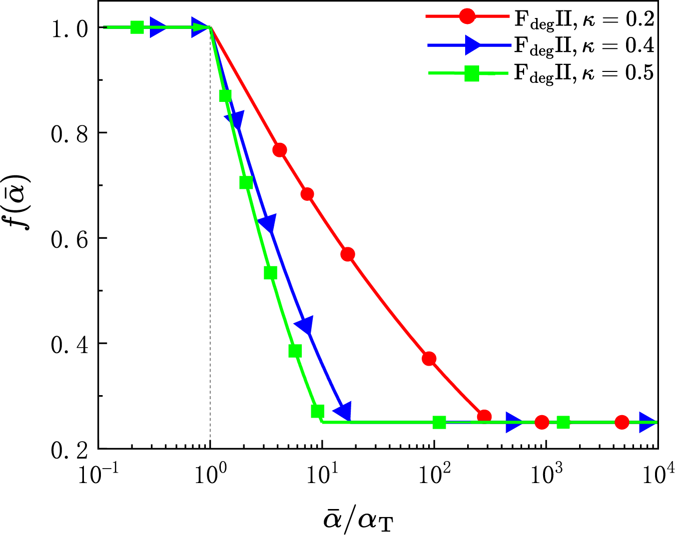
Figure 1: Fatigue degradation function
Thus, the dissipation energy density
where
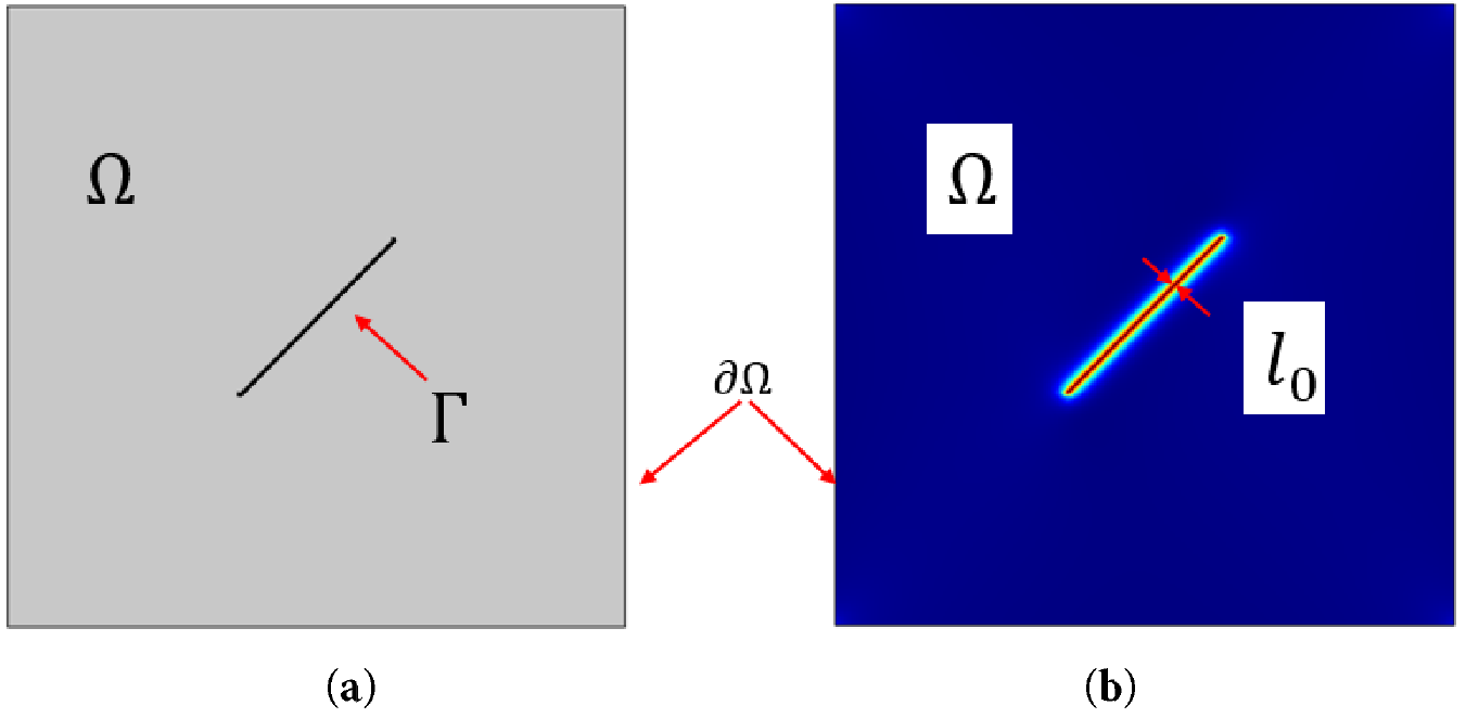
Figure 2: Sharp and diffusive fractures in poro-elastic medium: (a) Sharp fracture; (b) Diffusive fracture
Considering that the damage during the F-T cycles of concrete is mainly caused by tensile cracking due to frost heave, the elastic energy density
where the degradation function
The constitutive model couples material properties through Lamé parameters, with strain energy components [40]:
where the Lamé modulus
By incorporating fracture energy and elastic energy into the total energy functional, the multi-physically coupled energy functional can be formulated as:
The evolution of the phase-field variable is governed by the principle of energy minimization, representing the balance between fracture energy dissipation and elastic energy release. The governing equation is derived by seeking the stationarity of the total energy functional with respect to
To ensure crack irreversibility in accordance with the second law of thermodynamics. The maximum historical value of the energy driving force is introduced [39]:
The complete governing equation for fatigue behavior in the fracture phase-field can be expressed as:
With the corresponding boundary condition:
Having established the variational phase-field framework for fatigue damage in Section 2, we now extend this foundation to incorporate multiphysics coupling essential for modeling F-T behavior in concrete. The phase-field variable
3 Multiphysics Coupling Framework
A critical aspect of F-T damage in concrete is the tight coupling between its thermal, hydraulic, and mechanical response mechanisms. The pore structure characteristics of saturated concrete play a decisive role in the THM coupling mechanisms during F-T cycles. Accordingly, this section first introduces the PSD curve, which characterizes the pore structure features influencing ice crystallization and phase transition. Subsequently, based on the theory of pore ice formation, the calculated model of ice saturation are derived for the saturated concrete under F-T conditions, along with models describing the evolution of porosity, permeability coefficient, and pore pressure throughout the process. Finally, these evolution models are incorporated into a THM coupling framework, leading to the establishment of a THM-F coupled finite element model designed to simulate the damage progression in concrete subjected to F-T cycles.
3.1 Pore Structure Characterization and the Porosity Evolution under F-T Condition
The predictive capability of the proposed model derives from its ability to extrapolate pore structure evolution based on the initial PSD characteristics and fundamental physical principles, rather than relying on empirically measured PSD data at specific cycle numbers. The PSD function
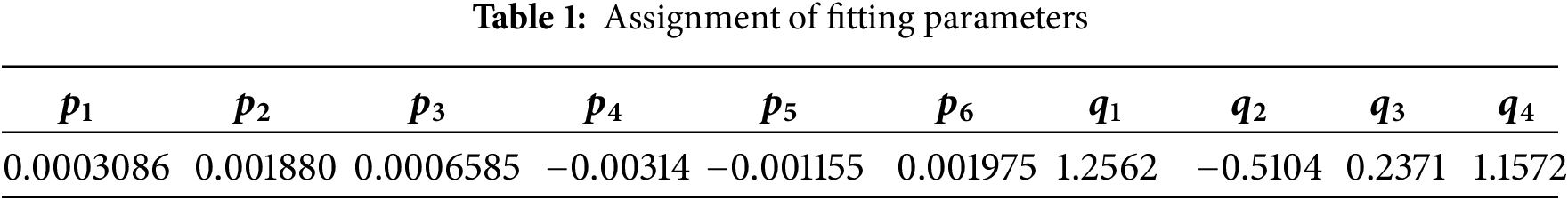
In this study, the PSD curve was quantitatively obtained through via Mercury Intrusion [42], a technique that infers the pore structure from the relationship between intrusion pressure and volume, based on the surface tension and incompressibility of mercury. As illustrated in Fig. 3, the PSD curve for the non-air-entrained concrete used in this work, validated against standardized test data from Reference [43], is mathematically represented by the following rational fitting function:
where
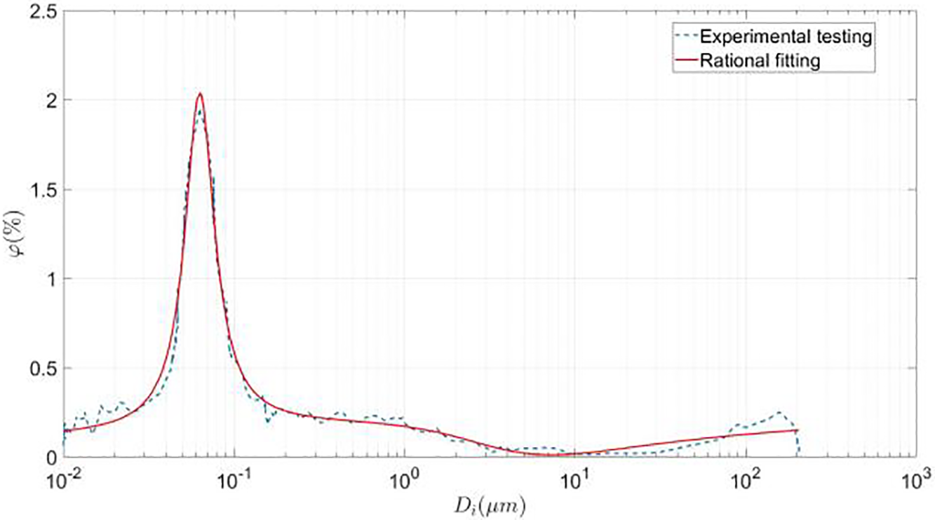
Figure 3: The pore size-distribution curve
According to the Gibbs-Thomson thermodynamic theory, the freezing point depression of pore water nonlinearly depends on the pore radius [11]. For saturated pores, this relationship is influenced by capillary effects described by the Young-Laplace equation, which states that the capillary pressure is inversely proportional to the pore diameter [43]. During the initial freezing stage, larger pores with greater curvature radii exhibit lower ice nucleation energy barriers, leading to preferential ice formation. As the thermal gradient intensifies, the phase transition front progressively propagates toward smaller pores, as shown in Fig. 4. The critical pore diameter
where,
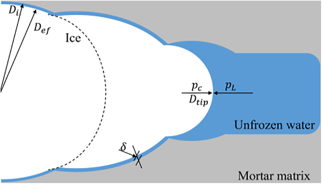
Figure 4: Schematic illustration of ice crystal growth morphology within pore structures (the ice crystal tip radius
Based on the physical definition of the critical pore diameter
where, n denotes the total porosity.
Experimental studies demonstrate that geometric disparities between pore throats and bodies induce a ‘F-T hysteresis’ effect, leading to asymmetric ice content evolution between freezing and thawing, where the freezing point is controlled by throat dimensions and the melting point is governed by body dimensions. To quantify this phenomenon, the ice content during thawing is reformulated as a temperature-dependent piecewise function [46]:
where the shape factor
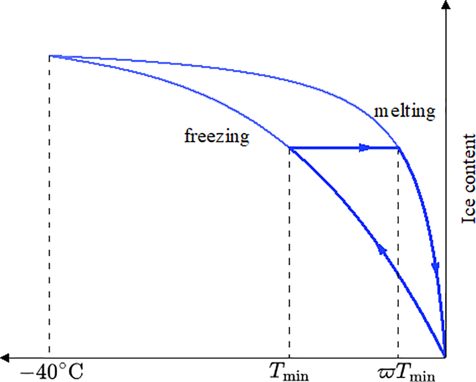
Figure 5: The evolution of ice saturation during F-T cycles
The degradation of concrete under F-T cycling originates from progressive damage to its microporous structure. Experimental studies reveal a two-scale deterioration pattern: at the macroscopic level, the total porosity increases with cycle number, while microscopically, the PSD shifts toward larger diameters. To capture this dual-scale evolution, the present study develops a microstructure-informed model that links phase-change-induced deformation to pore growth.
In the model, individual pores are idealized as cylindrical inclusions—a simplification supported by microstructural studies showing that pores in cementitious materials are predominantly elongated and interconnected [48]. This approach allows applying poromechanics theory to quantify eigenstrains induced by water-ice phase change [49]. During freezing, pore water is assumed to expand uniformly in all directions. The resulting deformation is partly reversible upon thawing, but a fraction accumulates as irreversible damage, leading to pore enlargement. The change in pore size after one F-T cycle is expressed through the recursive relationship:
here,
Not all pores recover equally. Larger pores experience more permanent expansion due to weaker constraint from the surrounding matrix and greater interaction with neighboring pores. Experimental observations suggest that deformation recovery decreases as pore size increases [2]. To reflect this size-dependent behavior, a segmented recovery function is introduced:
This function assigns higher recovery to smaller pores (0.99 for pores below 4 µm) and lower recovery to larger ones (0.97 for pores 60–100 µm), reflecting the increasing irreversibility of deformation with pore size.
Based on the pore size update rule in Eq. (19), the evolution of the PSD curve after N cycles is derived as:
here,
The total porosity after N cycles is obtained by integrating the updated PSD:
Using the initial PSD (e.g., Fig. 3), the model recursively computes the PSD for successive cycles (Fig. 6), capturing the migration of pore volume toward larger sizes and the corresponding increase in total porosity.
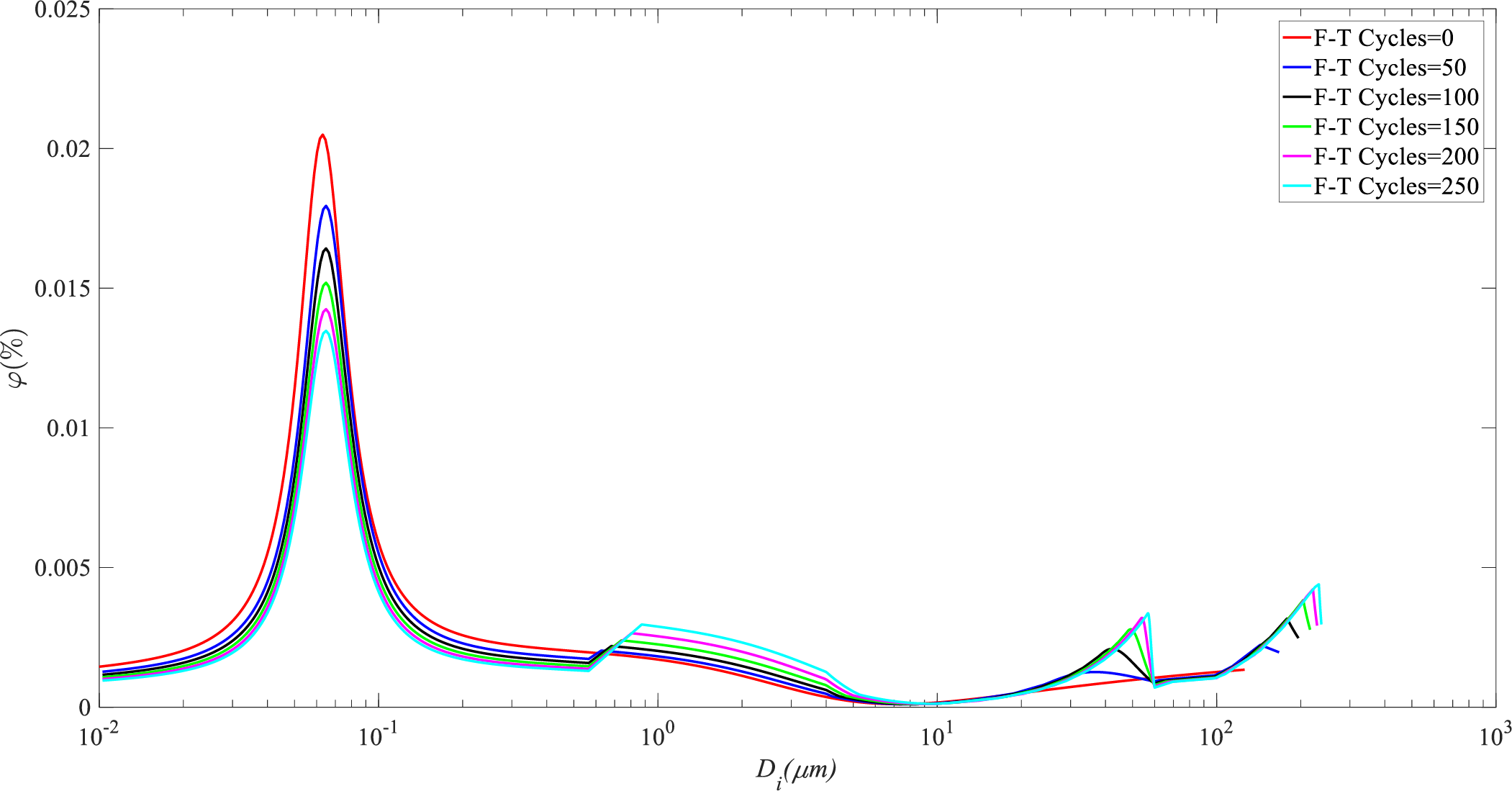
Figure 6: The aperture distribution curves after different number of F-T cycles
Fig. 6 illustrates the PSD curves predicted by the microscopic model for different numbers of F-T cycles. The simulation results align well with experimental trends: a substantial increase in the volume fraction of larger pores [2]. This shift visually demonstrates the cumulative effect of the non-recoverable frost deformation
3.2 Effective Permeability Coefficient and Effective Pore Pressure
Within the multiphysics-coupled F-T damage model of concrete, the dynamic evolution of permeability is synergistically regulated by pore structure reconfiguration and phase transition processes. Based on pore-wall adsorption effects, the intrinsic permeability
where the pore diameter correction coefficient
The macroscopic permeability
in the equation,
The effective permeability coefficient of unfrozen water
Specifically, the interval
As evidenced in Fig. 7, under constant initial porosity conditions, the permeability coefficient exhibits a characteristic exponential decay during individual F-T cycles, due to increasing ice content as temperature reduction. However, with increasing cycle numbers, the initial permeability at the start of each cycle displays a distinct stepwise escalation. Notably, after multiple cycles, the temperature sensitivity of the permeability coefficient intensifies, manifesting as accelerated decay rates within identical temperature reduction intervals as cycling progresses. This phenomenon indicates that repeated F-T processes progressively damage the pore structure, increasing the proportion of large-diameter pores and rendering the overall pore network more fragmented with enhanced connectivity, thereby elevating the baseline permeability at the onset of subsequent cycles.
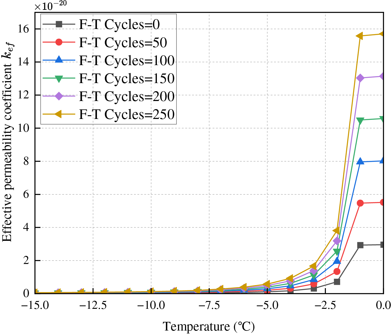
Figure 7: The permeability evolution with temperature at different FTC
Regarding the evolution of pore pressure during freezing, it is essential to distinguish between the total pore pressure and the effective pore pressure. The total pore pressure refers to the pressure within the pore fluid mixture. In contrast, the effective pore pressure is the net pressure acting on the solid skeleton, which is critical for calculating the effective stress that governs mechanical deformation.
Based on the Young-Laplace thermodynamic equilibrium equation [8], the pressure difference across the ice-water interface in fully frozen pores is expressed as:
where
During pore freezing, the effective pore pressure
where
The evolution of the pressure parameter
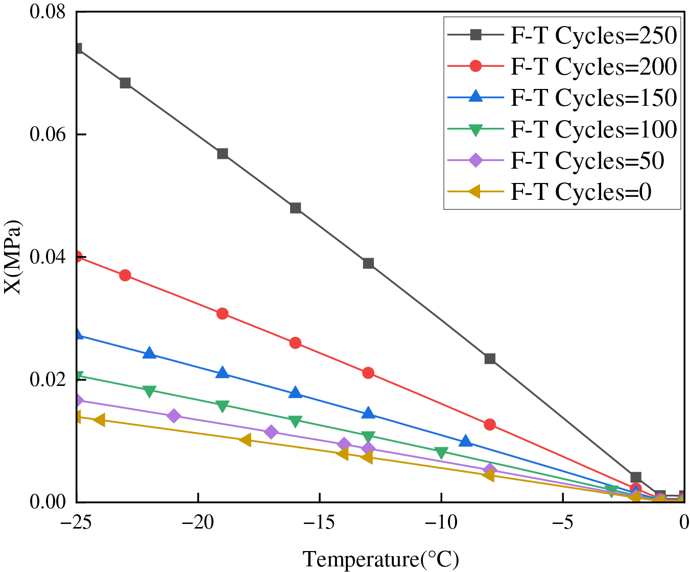
Figure 8: Evolution of pressure parameter
3.3 Governing Equation for THM System
The constitutive behavior of porous materials under F-T conditions can be derived from poroelasticity theory. The relationship between effective stress
where
Incorporating thermal expansion effects through the Duhamel-Neumann formulation [51], the constitutive relationship becomes:
here
The mechanical equilibrium equation under static loading conditions is:
where
Substituting Eqs. (6), (29) and (30) into the equilibrium equation yields:
with corresponding boundary conditions:
This formulation comprehensively characterizes the coupled interactions among seepage, thermal, damage phase, and stress fields [23].
3.3.2 Mass Balance for Pore Water
Based on Powers’s static water pressure hypothesis [6], the mass variation of water within closed pores in a saturated porous medium results from the combined effects of water consumption due to ice formation and the mass flux of unfrozen water migrating across the boundary. The phase transition and water flux obey liquid mass conservation, expressed as:
where
Following Darcy’s law, pore water velocity relates to hydraulic head [52]:
where
The temperature-dependent densities of ice and water during phase transition are explicitly incorporated [22,50]:
Poromechanics theory [51,53] establishes quantitative relationships between pore structure evolution and F-T-induced damage through strain-porosity coupling equations, while incorporating cumulative porosity damage over successive F-T cycles. The governing equation is formulated as:
Combining these relationships yields the seepage field governing equation:
where
Material damage significantly alters hydraulic properties. The computational domain is divided into a reservoir zone
where
The hydraulic characteristics are then expressed as:
where the subscripts
The boundary conditions are specified as:
3.3.3 Energy Conservation for Heat Transfer
The temperature field in saturated porous materials is governed by the energy conservation equation:
where
here
The effective thermal conductivity
where
The released heat rate
The temperature-phase field coupling is established through the temperature-dependent thermal conductivity [56]:
where
The boundary conditions are specified as:
where
These equations capture the coupled THM processes in the concrete during F-T cycles, allowing for the simulation of damage evolution and material behavior under such conditions.
3.4 Cross-Scale Coupling Modelling Scheme
This model establishes a comprehensive multiphysics framework to capture the key coupling pathways governing F-T damage evolution in saturated porous media. The phase-field variable interacts with the mechanical properties by degrading the elastic energy and simultaneously modulates the spatial distribution of permeability and thermal conductivity, thereby linking damage evolution with both seepage and thermal responses. The temperature field, influenced by ice-water phase transition and latent heat exchange, alters the pore-scale ice content, reshaping the pressure distribution and inducing thermal strains that feed back into the mechanical behavior. A bidirectional coupling exists between seepage and mechanical fields: pore pressure generated by freezing acts as an internal stress source, while deformation-induced volumetric changes affect pore connectivity and fluid transport. Stress redistribution drives the progression of damage through the phase-field, compounded by fatigue accumulation under cyclic loading. Repeated F-T cycles further modify the pore structure and permeability in a cumulative manner, forming a feedback loop that accelerates the degradation of transport properties and structural integrity, as illustrated in Fig. 9.
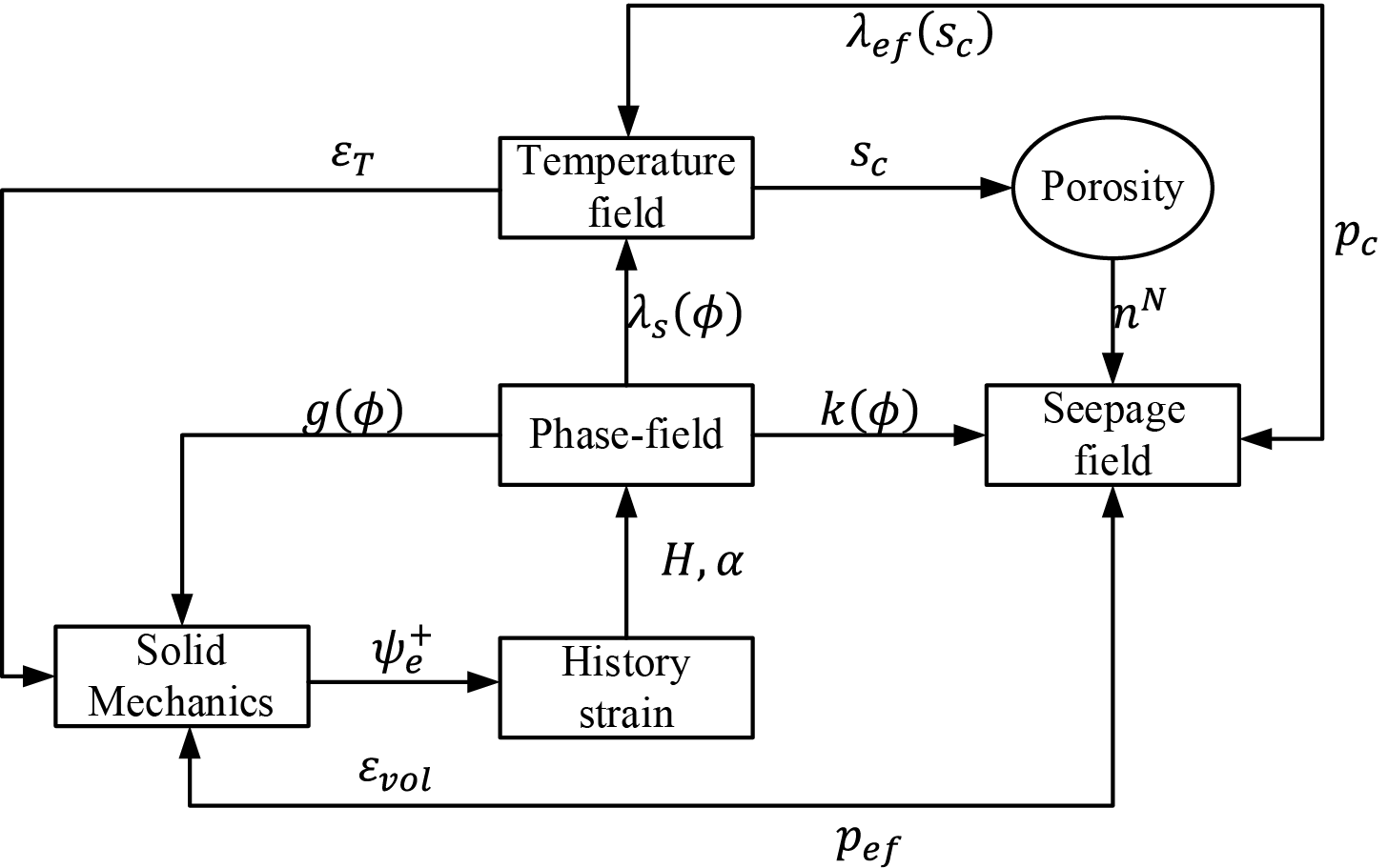
Figure 9: Cross-scale coupling modelling scheme
4 Numerical Discretization and Implementation
This section establishes a computational framework for modeling multiphysics-coupled fracture evolution in concrete under F-T cycles based on phase-field theory. The numerical implementation employs a hybrid space-time discretization strategy: the spatial domain is discretized using the finite element method, while temporal discretization is achieved via the backward differentiation formula. To effectively address numerical instabilities arising from strongly coupled multiphysics interactions, we propose a staggered iterative solution scheme coupled with an adaptive time-stepping control mechanism to balance computational efficiency and convergence robustness.
4.1 Weak Form and Discretization
The weak forms of the governing equations for F-T damage are expressed as:
The spatial discretization scheme is constructed using the Bubnov-Galerkin weighted residual method [41], where the continuous field variables and admissible variations are formulated as:
the continuous field variables
with
Following analogous methodology, the gradient terms and corresponding variational formulations for each physical field are derived as:
the differential operator matrices
To ensure the well-posedness of the discrete system, the selection of weight functions preserves mathematical arbitrariness, leading to the matrix formulation of the discretized governing:
where
4.2 Time Integration and Nonlinear Iterative Solution
The F-T cycling process inherently constitutes a complex physical system involving coupled THM phase transition interactions, exhibiting pronounced nonlinear characteristics and stiffness evolution over time. The ice-water migration and pore structure reconfiguration during phase transitions induce abrupt temporal gradient variations in field variables, imposing stringent requirements on the numerical stability and computational accuracy of temporal integration algorithms.
This study employs the backward differentiation formula for temporal discretization, which maintains numerical stability while achieving second-order temporal accuracy, making it particularly suitable for strongly nonlinear coupled systems. The discretized form of the temporal derivative term is expressed as:
the variables
The updating algorithm for fatigue damage evolution parameters adopts an incremental accumulation scheme, where historical damage variables are progressively updated through cyclic integration of localized energy dissipation metrics.
with
where
This study develops a multiphysics-coupled numerical model on the COMSOL Multiphasics platform [41], employing a modular equation framework to simulate the complete F-T damage evolution process. The model incorporates six sets of core governing equations, as detailed in Table 2.

The computational framework employs a hybrid discretization strategy:
(1) Spatial discretization: Phase-field variable
(2) Temporal evolution: History-dependent variables
(3) Nonlinear solver configuration: The system exhibits strong nonlinearity due to the stiffness degradation caused by
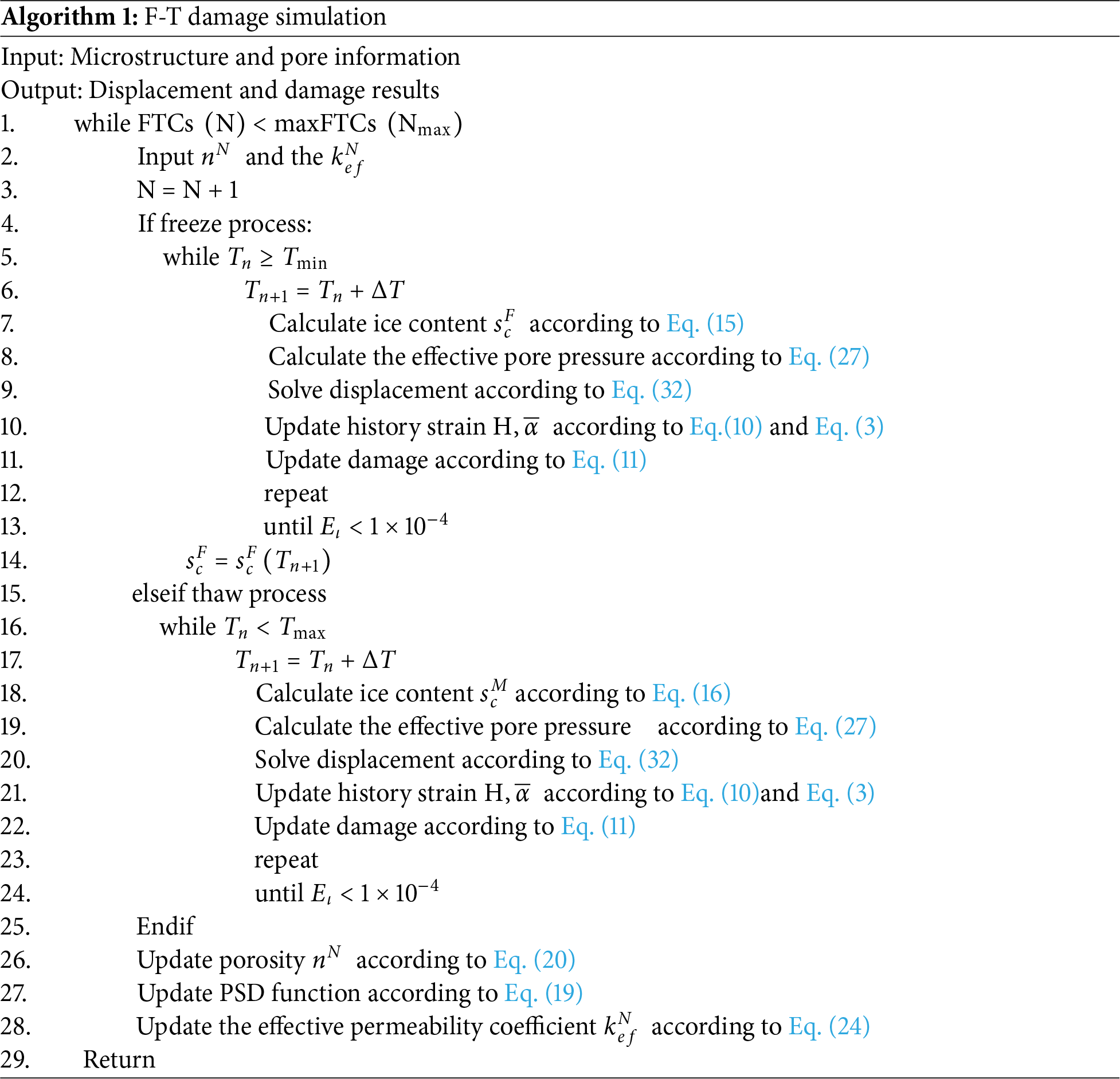
To implement the computational procedure effectively, a step-by-step algorithm is established as summarized in Algorithm 1, which outlines the sequential solving strategy for the F-T cycles.
This section validates the proposed multiscale framework using experimental data from Wang et al. [58], which involve uniaxial compression tests on concrete subjected to rapid F-T cycles [59]. Two-dimensional symmetric model is constructed to replicate the test specimen, incorporating a mesostructured composed of aggregates, ITZ and mortar matrix. The accuracy and reliability of the proposed model will be verified by comparing the simulated temperature field and mechanical response curves with experimental measurements.
5.1 Geometrical Modeling and Parametric Framework
Utilizing the mirror symmetry characteristics of the specimen in orthogonal planes, this study establishes a quarter-symmetric model
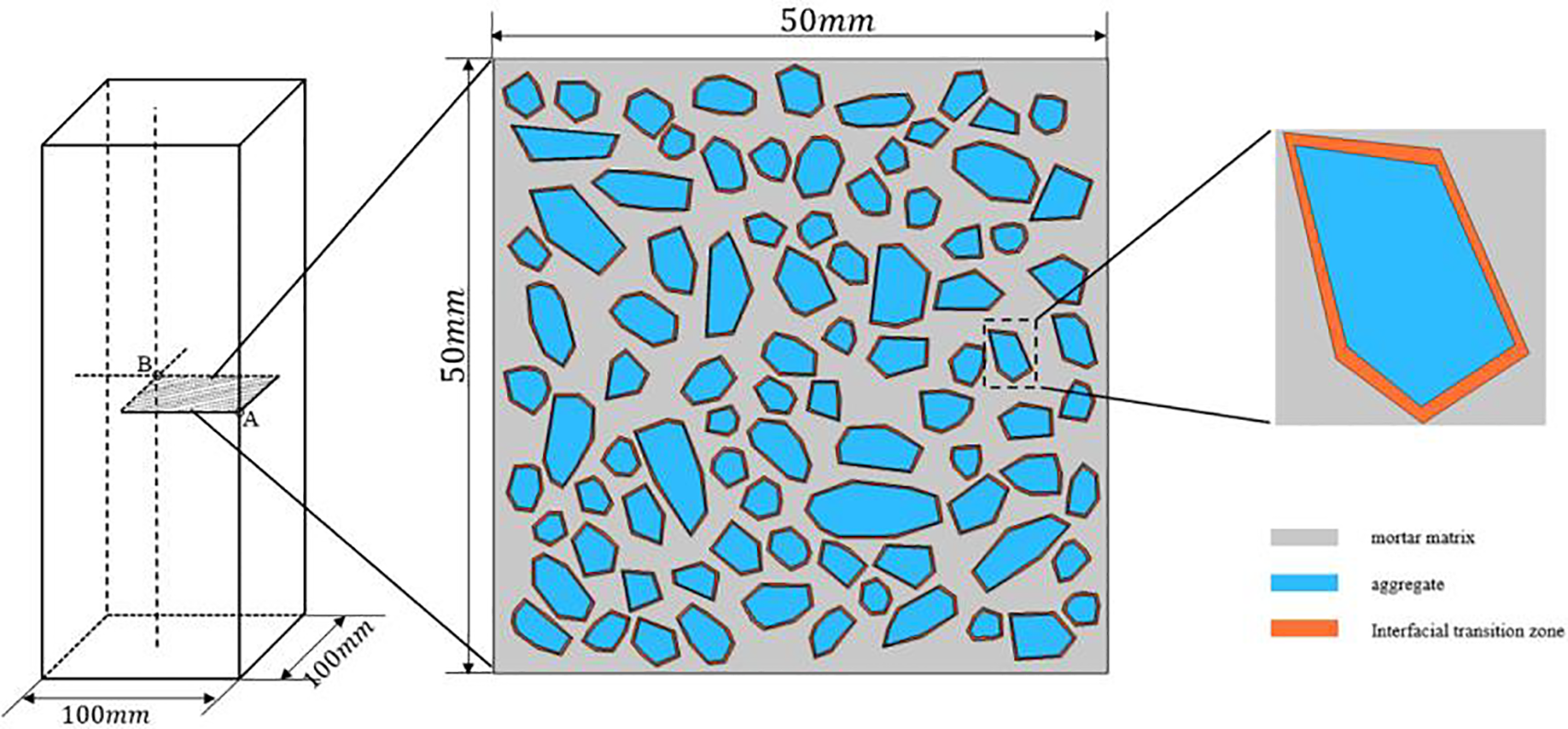
Figure 10: The concrete sample with randomly distributed aggregates
To characterize the pore heterogeneity in the matrix material, a multi-scale self-similar porosity random field is generated using the diamond-square algorithm [60], as shown in Fig. 11.
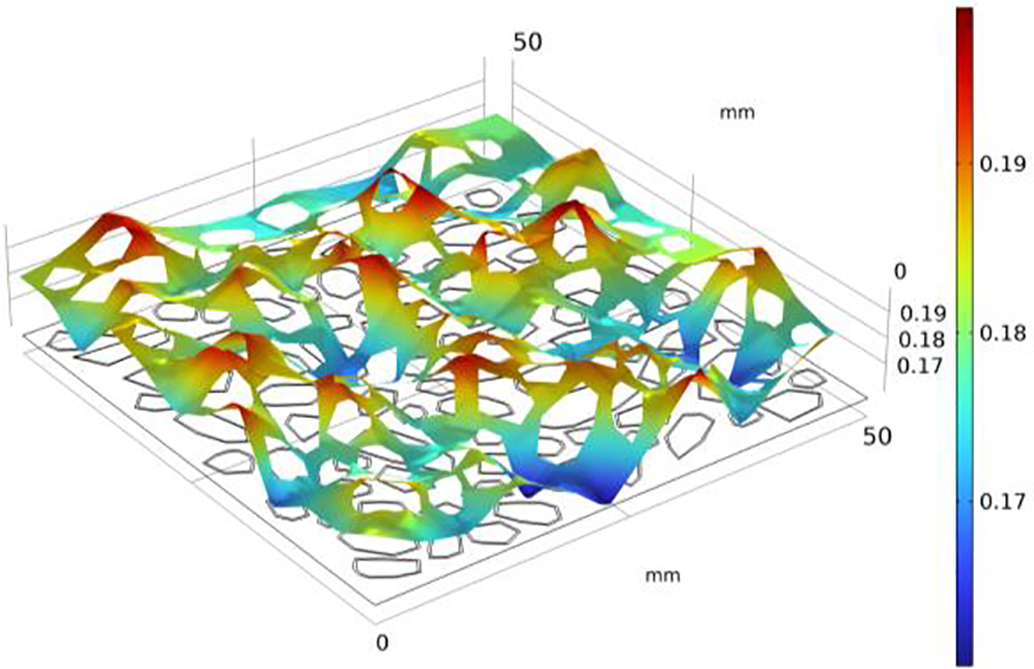
Figure 11: Randomly distributed porosity
This modeling method captures porosity heterogeneity from the specimen scale down to the microscale, offering a high-resolution, statistically self-similar basis for simulating the spatially nonuniform evolution of F-T damage.
In order to enhance clarity, the material parameters are organized into three separate tables according to their physical roles in the model.
The phase-field fracture parameters associated with mortar, aggrates, and the ITZ are summarized in Table 3. Mortar and ITZ are modeled as temperature-dependent poroelastic media, while aggregates-due to their significantly higher stiffness and negligible permeability-are treated as non-damageable inclusions. The critical energy release is obtained through sensitivity analyses and previous investigations [61,62], and the phase-field length scale is set with reference to the characteristic material dimensions.

The THM parameters governing the multiphase F-T behavior of the three constituents are provided in Table 4. Mortar and ITZ properties are derived from experimental datasets and established literature, with interfacial properties further determined by Nagai et al.’s regression formula [63] based on water-to-cement ratios. Aggregate properties are simplified to thermal conduction only, given their impermeability. Fatigue-related parameter
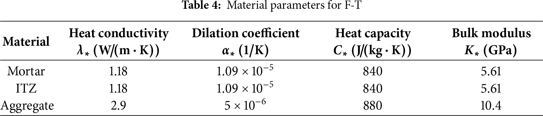
Table 5 summarizes the material constants associated with the ice-water phase transition for F-T analysis [22,55,64]. The dynamic viscosity of water is defined as a temperature-dependent function, defined as [64]:
5.2 Boundary Conditions Configuration
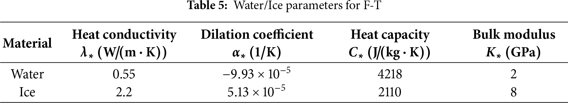
Following ASTM C666-A standard procedure, specimens underwent 28-day water curing prior to F-T cycling in sealed rubber containers. Programmable thermal controllers imposed boundary conditions with cyclic protocols: each 6-h cycle included linear cooling from 20°C to −25°C at 0.75°C/min (60 min), 120-min isothermal holding, and reheating to initial temperature at identical rates (Fig. 12a). High-precision thermocouples and strain gauges were installed at the specimen surface (Point A) and geometric center (Point B), respectively, to monitor real-time temperature and strain evolution.
Figure 12: FTC boundary setting: (a) Cyclic temperature; (b) Boundary conditions
The boundary conditions in the numerical model were rigorously configured to replicate the experimental conditions (Fig. 12b). The surface temperature loading was applied using the measured temperature profile, while the temperature variation at the core was validated by comparing simulation results against the recorded data at monitoring Point B.
Mechanical boundary conditions assumed zero initial stress and strain states. Hydraulically, initial pore pressure was set to
Following 75 F-T cycles, specimens were subjected to 48-h isothermal curing in a temperature-controlled water tank (20°C ± 1°C) to dissipate residual thermal stresses, prior to uniaxial compression testing. The compressive damage simulation employed the following boundary configurations: the bottom surface of the specimen was fully constrained in all degrees of freedom, while the top surface was subjected to displacement-controlled loading with a step size of 0.1 mm, as illustrated in Fig. 13. The material parameters in the numerical model were assigned based on the experimentally measured elastic modulus and Poisson’s ratio of the F-T damaged specimen to accurately capture the cumulative damage effects.
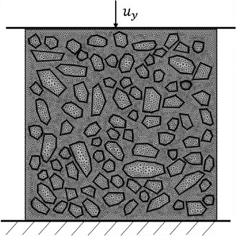
Figure 13: Simulation model for compression
5.3 F-T Damage and Static Strength
Fig. 14 illustrates a comparative analysis of the temperature evolution at the specimen’s geometric center (Point B) between experimental measurements and numerical simulations during a single F-T cycle. The simulated results exhibit consistent trends with experimental data, accurately capturing the phase transition plateau near 0°C caused by latent heat release during water-ice transformation. The plateau duration is governed by the material’s thermal conductivity, pore structure, and saturation conditions.
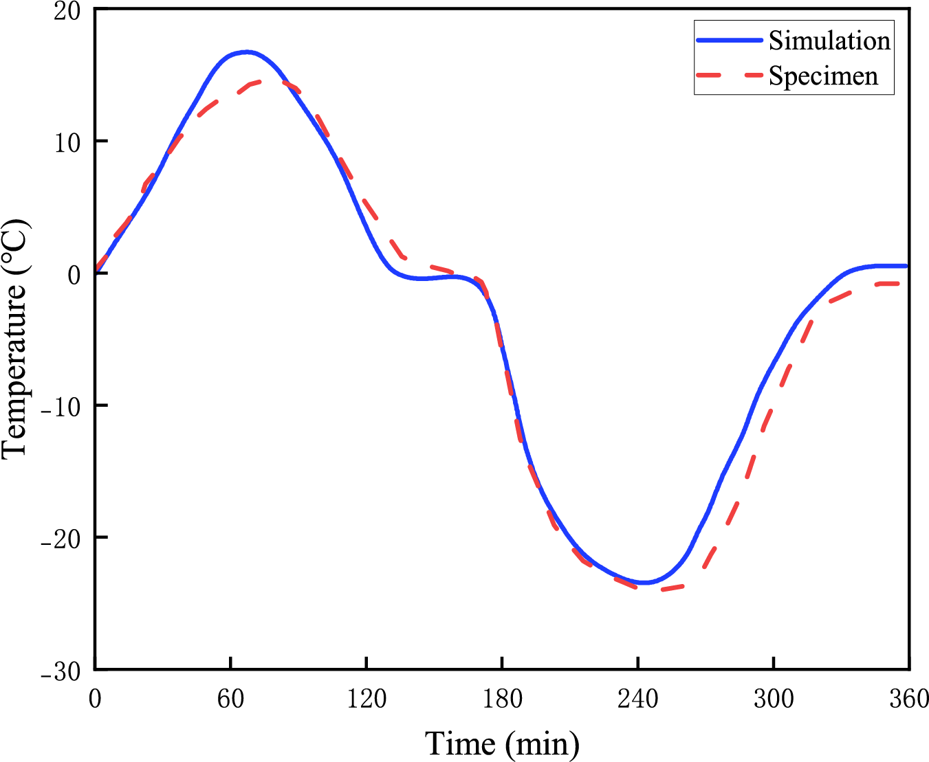
Figure 14: Temperature variation curve of material center point (B)
To introduce varying degrees of F-T damage prior to analyzing axial compression responses, unconstrained expansion during 75 F-T cycles (FTCs) was simulated, corresponding to experimental procedures by Wang et al. [58]. Fig. 15 presents simulated results of free FTC expansion, serving as initial conditions for subsequent axial compression analysis. The residual strain after each FTC constitutes the most critical parameter, which can be linked to other material properties [65]. Consequently, once simulated residual strains match experimental measurements, FTC-induced damage observed in tests can be replicated by the model. Fig. 15a compares simulated and experimentally measured FTC strain histories, demonstrating that both datasets exhibit consistent net expansive strain accumulation, with simulated trends aligning closely with experimental observations. Quantitative analysis reveals a post-75-cycles residual strain of
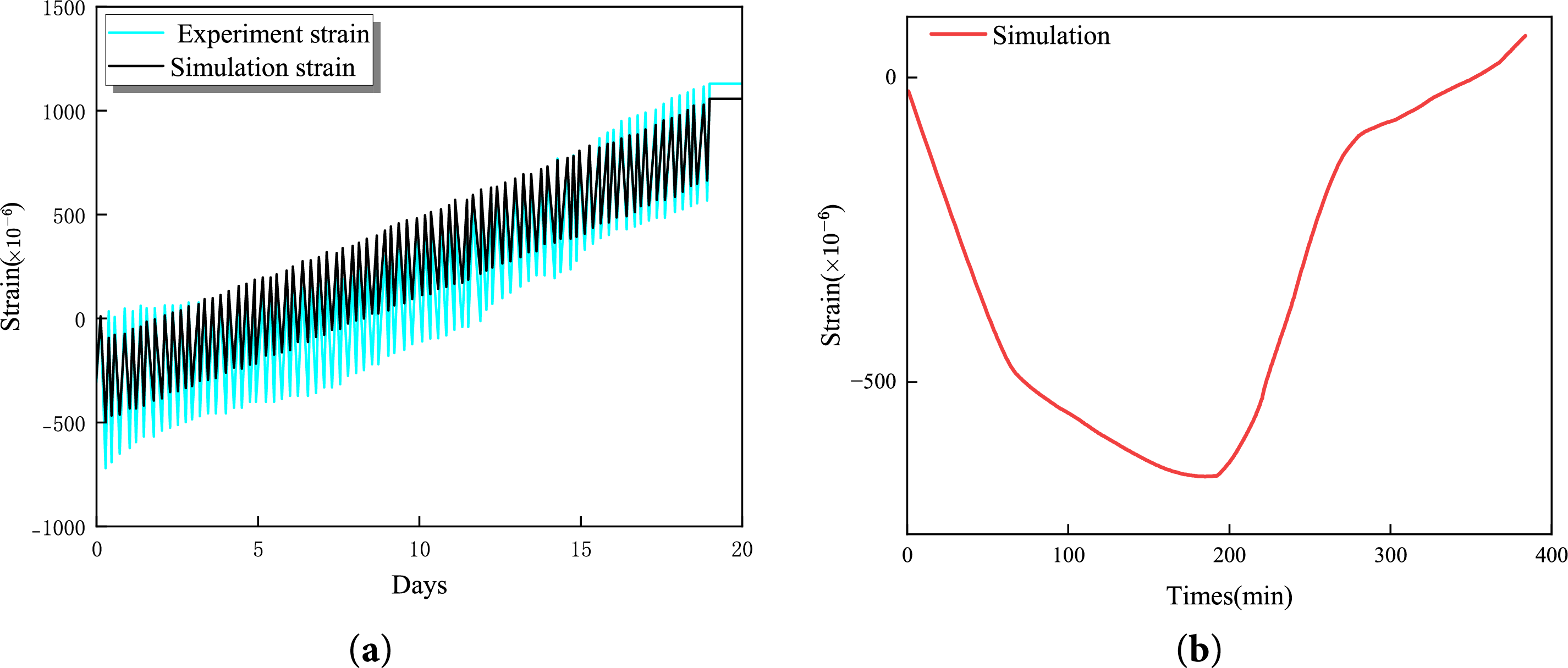
Figure 15: Strain history comparison: (a) Simulated cyclic strain and experimental measurements in 75 FTC; (b) First cycle strain
The dynamic strain response during the initial F-T cycle displays characteristic biphasic behavior in numerical results as illustrated in Fig. 15b. This behavior arises from competing thermal and phase-change effects: during initial cooling stages, rapid surface thermal contraction generates compressive strains near the boundaries. However, as temperatures continue to decrease below the critical freezing point, pore water begins to freeze and expand, generating significant crystallization pressure that reverse the strain direction and produce net expansion. The transition occurs when ice-induced expansion forces overcome thermal contraction effects [58].
The framework effectively resolves transient interactions between thermal gradients and phase-change-induced stresses, capturing localized damage initiation at material heterogeneity zones. Crack propagation pathways demonstrate preferential alignment with interfacial transition regions, consistent with microscopic observations of frost-damaged specimens. This validation confirms the model’s capacity to simulate coupled thermo-mechanical degradation processes while maintaining physical consistency across scales.
Fig. 16 compares the axial compressive failure modes between pristine specimen (Fig. 16a) and one subjected to 75 F-T cycles (Fig. 16b). Numerical simulations reveal that the failure of undamaged specimens is dominated by shear bands, exhibiting typical X-shaped intersecting crack propagation paths. In contrast, F-T damaged specimens demonstrate distributed network-like crack growth along interfacial transition zones (ITZ), with cracks preferentially developing at weakened aggregate-mortar interfaces, the simulation results are consistent with experimental observations [58]. This phenomenon originates from the pre-damaged effect induced by F-T cycles in ITZ regions, repeated phase transitions generate microcracks at interfaces, significantly degrading their mechanical properties. Consequently, subsequent compressive loading concentrates damage in pre-damaged areas, creating a synergistic amplification mechanism between F-T and mechanical degradation. Both experimental and numerical results uncover the reconfiguration of material failure modes by frost damage: F-T pre-damage not only reduces overall strength but also alters crack propagation pathways, thereby modifying failure mechanisms. The numerical model successfully reproduces the transition from shear-dominated failure mechanisms. This phenomenon reveals the reconfiguration mechanism by which F-T damage alters material failure modes, providing a theoretical foundation for predicting multi-stage coupled degradation processes.
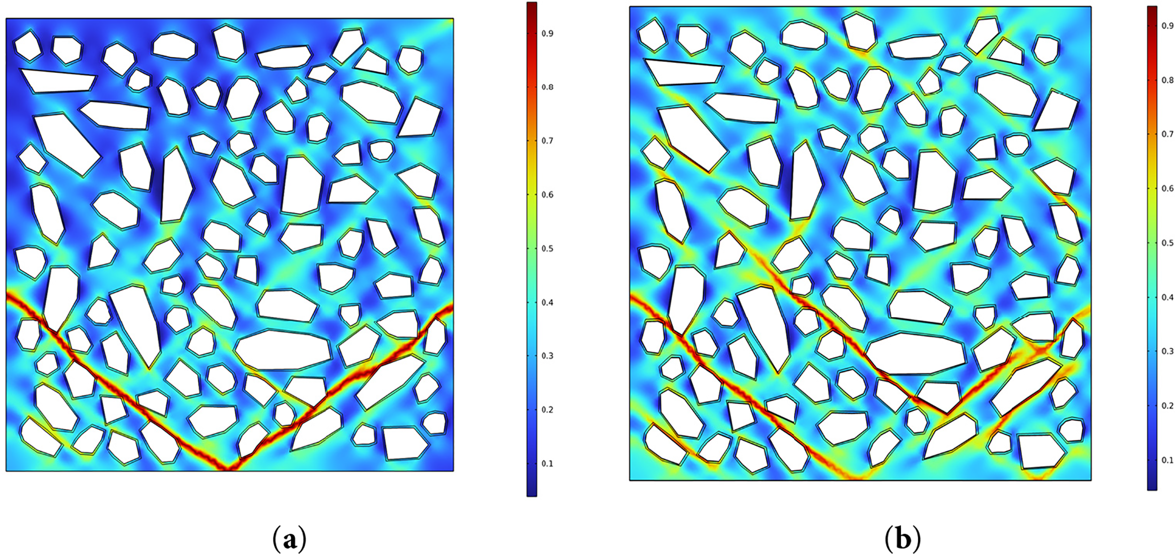
Figure 16: Damage patterns under axial compression: (a) FTC_0; (b) FTC_75
Fig. 17 compares the experimental (dashed line) and simulated (solid line) stress-strain curves of concrete specimens under axial compression, normalized against the room-temperature peak strain
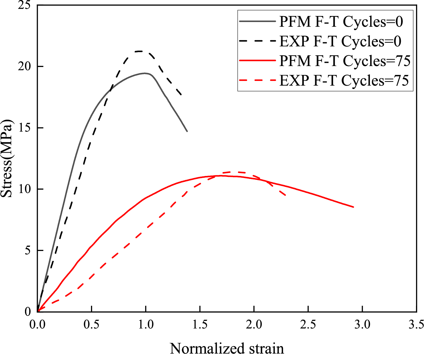
Figure 17: Compressive stress-strain curves
The simulation accurately captures two key phenomena: (1) strength reduction and ductility enhancement, and (2) stiffness recovery at higher stress levels. Analysis of the phase-field variable evolution during compression reveals that this stiffness recovery primarily results from microcrack closure under increasing compressive loads. As stress levels rise, existing microcracks gradually close, restoring some load transfer capacity through improved interfacial contact. Additionally, stress redistribution occurs from heavily damaged regions to relatively intact areas, further contributing to the apparaent stiffness recovery. This mechanism is particularly pronounced in F-T damaged specimens dur to the distributed nature of frost-induced microcracking. This partial stiffness recovery, emerging after initial degradation, provides new insights into concrete’s performance restoration mechanisms following F-T damage.
5.4.1 The Evolution of F-T Damage
The multiphysics-coupled model enables controlled characterization of frost damage progression, as illustrated by damage contour maps after 25, 50, 75, and 100 F-T cycles (Fig. 18a–d). Numerical investigations reveal that initial damage nucleation preferentially occurs in regions of significant microstructural heterogeneity, driven by thermally induced pore water migration and nonuniform stress fields:
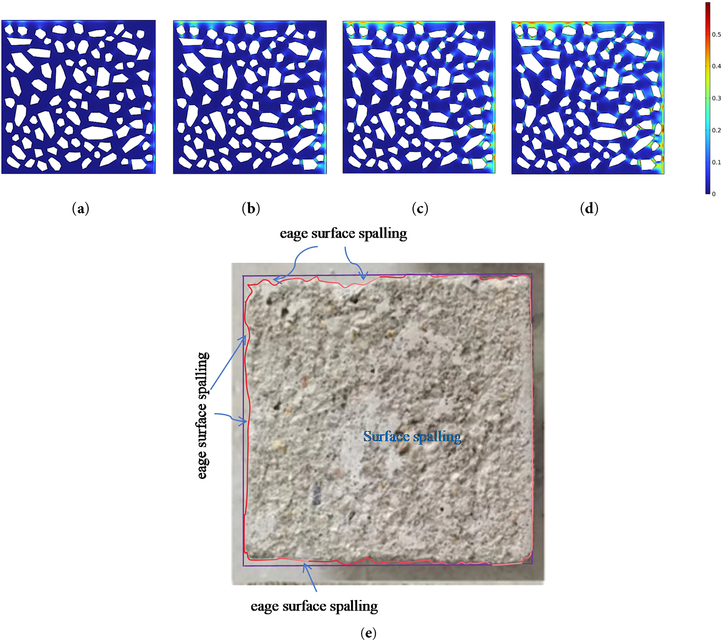
Figure 18: Comparison of morphology and simulation result of concrete F-T damage: (a) FTC = 25; (b) FTC = 50; (c) FTC = 75; (d) FTC = 100; (e) Experimental observatiaon
(1) Surface damage initiation: Thermal-hydraulic-mechanical interactions concentrate volumetric strain from ice-water phse change in the weakest boundary zones, leading to nucleation of microcracks at the surface;
(2) ITZ-dominated propagation: Stress concentration and crack advancement preferentially follow ITZ due to dual weakening effects-reduced elastic modulus and compromised compactness.
As cycling continues, damage spreads progressively. Within the ITZ, capillary migration of unfrozen water and tensile stresses from ice crystal growth synergistically drive cracks from the aggregate-matrix interface toward the specimen center. These microcracks gradually interconnect, producing crack morphologies that closely match experimental observations (Fig. 18e). Concurrently, surface initiated cracks coalesce, ultimately resulting in spalling and surface delamination.
After 100 F-T cycles, the simulated damage pattern-dominated by crack networks along the ITZ-exhibits strong spatial correlation with microscopic imagery, confirming the model’s capability to capture the underlying mesoscopic damage mechanisms under coupled thermal, hydraulic, and mechanical loading.
5.4.2 F-T Hysteresis Phenomenon
Fig. 19 illustrates the spatiotemporal evolution of ice saturation at boundary Point A and central Point B during F-T cycles, along with their thermodynamic path dependence, characterized as follows:
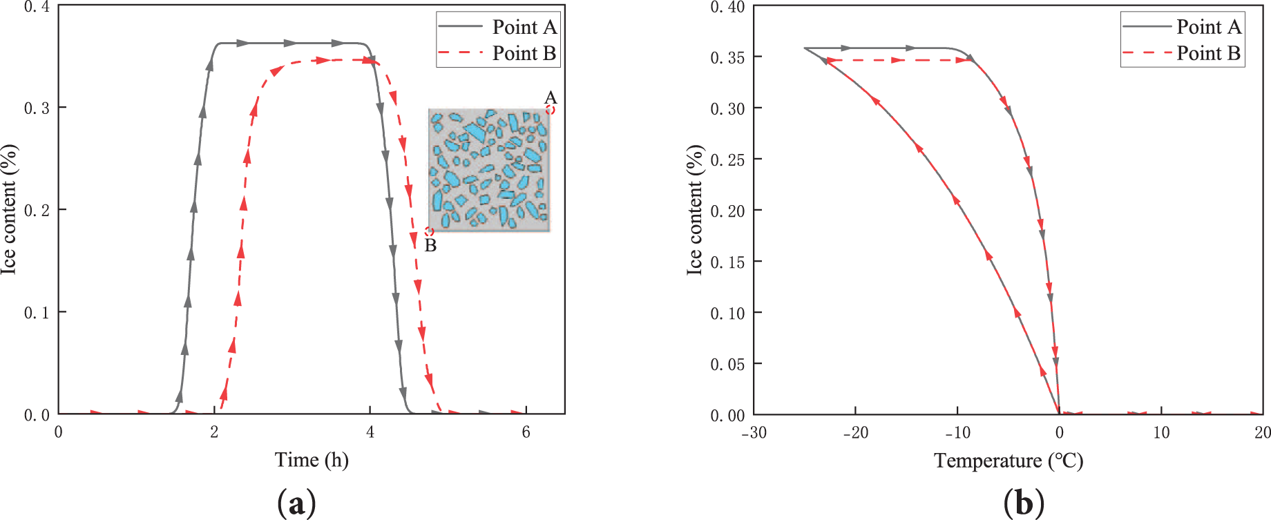
Figure 19: Ice saturation evolution: (a) Temporal evolution of ice saturation; (b) Temperature-dependent evolution of ice saturation
(1) Temporal evolution (Fig. 19a): The peak ice saturation at Point B lags significantly behind Point A, with a 4% reduction in peak magnitude. This delay reflects spatiotemporal heterogeneity in heat conduction under temperature gradients, where slower thermal equilibration in the interior governs phase-change dynamics.
(2) Temperature-dependent evolution (Fig. 19b): Ice saturation-temperature curves form closed hysteresis loops, with freezing-phase supercooling exceeding thawing-phase values. This asymmetry aligns with phase-transition hysteresis mechanisms documented in [46], confirming the thermodynamic irreversibility of ice-water transformations.
Faster heat exchange at boundary regions creates divergent phase-change kinetics compared to the interior. Such spatiotemporal asynchrony generates non-equilibrium stress fields that redirect damage evolution paths, explaining the gradient-driven accumulation of F-T damage.
5.4.3 The Influence of Water-Cement Ratio on F-T Damage
The water-cement (w/c) ratio critically governs the microstructure andmacroscopic mechanical properties of concrete, directly influencing frost resistance [63,66]. Adopting Kosaka et al.’s model [67] that quantifies w/c-dependent elastic modulus, specimens with w/c = 0.4, 0.5 and 0.6 were analyzed to assess damage sensitivity.
The relative elastic modulus loss rate
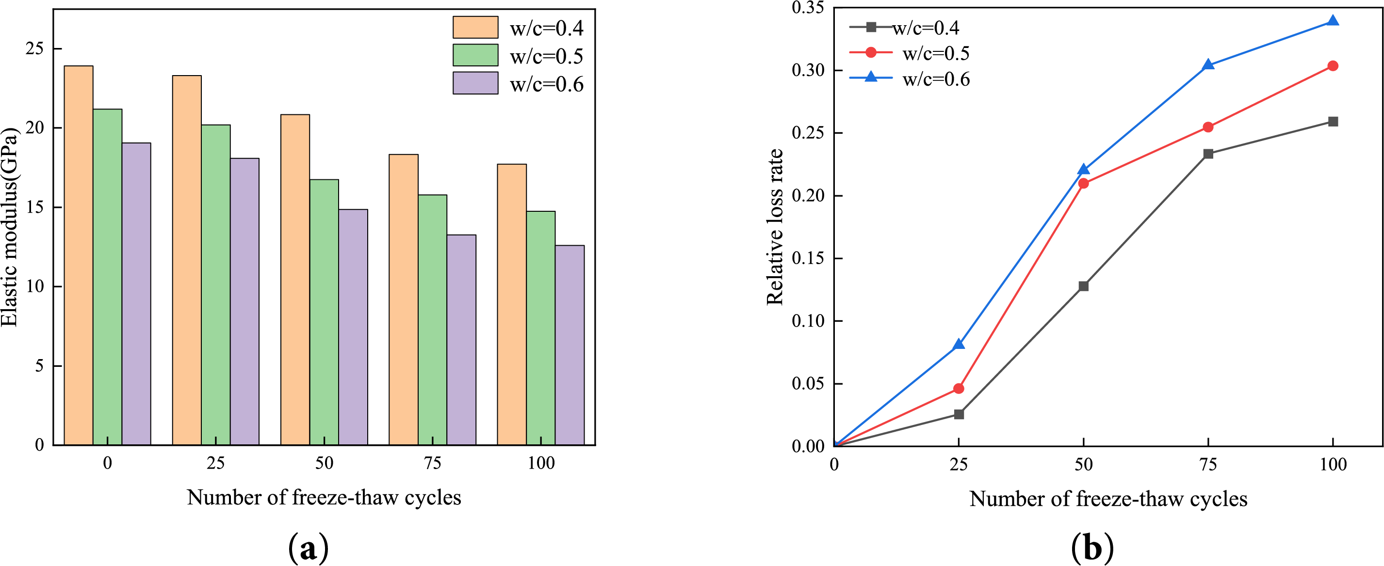
Figure 20: Relative loss rate of Elastic modulus: (a) Bar chart of elastic modulus; (b) Line chart of elastic modulus loss rate
At 25 cycles,
At 100 cycles,
Higher w/c ratios amplify damage due to dual mechanisms:
(1) Elevated capillary porosity: Increased pore connectivity enhances frost heave pressure transmission;
(2) Unhydrated particle accumulation: Residual unreacted particles reduce cementitious phase strength [63,66].
The synergy between porous network development and weak phase concentration accelerates crack propagation and structural deterioration under cyclic freezing-thawing.
5.4.4 Impact of Air Content on F-T Damage
As illustrated in Fig. 21, the introduction of entrained air bubbles into concrete significantly optimizes pore structure, enhancing frost resistance. Fig. 21a presents PSD curves for specimens with varying air contents. Increasing air content shifts the distribution from a broad scatter to a concentrated range of small-to-medium pores, indicating improved uniformity and controllability of the pore structure.
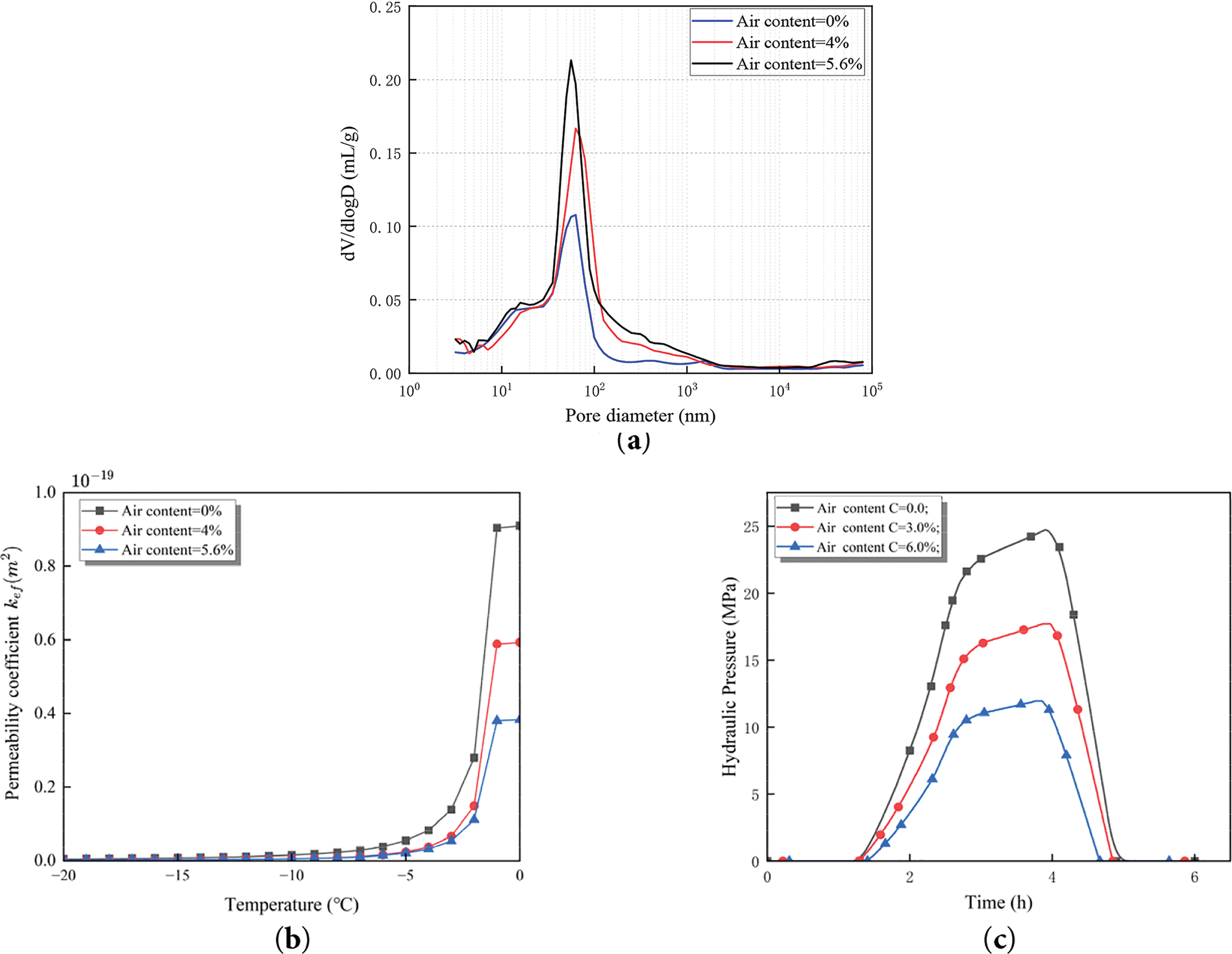
Figure 21: Average hydraulic pressure: (a) The PSD function [69]; (b) The effective permeability coefficient; (c) Hydraulic pressure
Based on the PSD functions in Fig. 21a, the temperature-dependent evolution of effective permeability coefficients for specimens with different air contents is calculated as illustrated in Fig. 21b. Results demonstrate that higher air contents correlate with denser pore networks and significantly reduced permeability.
Fig. 21c compares the temporal evolution of internal pore pressures during F-T cycles. Specimens with higher air contents consistently maintain lower average pressure levels. For instance, the maximum internal pressure in specimens with 5.6% air content is 12 MPa, representing a 52% reduction compare to non-air-entrained specimens (25 MPa). This highlights the buffer effect of air bubbles in mitigating ice-induced pressure peaks, thereby delaying crack initiation and propagation. The trend suggests that increased air content shortens capillary water migration paths during freezing, reducing hydrostatic pressure generation [6,12] and alleviating localized damage.
In summary, optimizing air content enables synergistic improvements in pore structure and permeability under multiphysics coupling, effectively suppressing peak hydraulic pressures and significantly enhancing concrete’s frost durability.
This study proposes a novel multiphysics-coupled computational framework for F-T damage, with core innovations extending existing phase-field variational fatigue theory to thermos-hydro-mechanical systems and establishing cross-scale linkages between dynamic porosity evolution and fatigue damage. Specifically, leveraging the variational nature of phase-field methods, the damage phase-field variable is bidirectionally coupled with thermal conduction, hydraulic transport, and mechanical constitutive equations. Critically, the framework abandons conventional static porosity assumptions and introduces a cycles-dependent dynamic porosity evolution equation to iteratively characterize progressive microstructural degradation. This equation treats post-cycles porosity as the initial condition for subsequent cycles, inherently capturing damage accumulation path dependency. By mapping dynamic porosity to permeability evolution, the model quantitatively resolves transport property deterioration during F-T cycling.
Numerical investigations reveal key mechanisms:
(1) Phase-transition dynamics: Initial F-T stages induce contraction from rapid cooling, followed by ice-expansion-dominated volumetric growth, confirming the critical transition mechanism from contraction to expansion.
(2) Mesoscale damage evolution: During the initial stage (<25 cycles), discrete micro-damage localized near aggregate boundaries and ITZ. As cycling reaches 50, surface damage coalesces into connected networks, while internal damage remains localized. Beyond 75 cycles, internal microcracks propagate along ITZ, forming networked crack trends with exacerbated surface spalling.
(3) Mechanical degradation: Post-F-T compressive strength decreases by 45%, with higher water-cement ratios accelerating performance deterioration, highlighting porosity’s pivotal role in frost susceptibility.
(4) Air entrainment efficacy: Optimized pore structure via air entrainment reduces permeability and suppresses hydraulic pressures, diminishing peak damage stress attenuation by 18%-22%, validating microstructural control as an effective frost-resistance strategy.
The model successfully reproduces the transition from isolated microcracks to interconnected fracture networks while quantitatively predicting macroporosity evolution and its correlation with mechanical degradation. This capability provides a robust tool for assessing durability thresholds and optimizing frost-resistant concrete designs in cold regions. This study advances the state of the art by developing a comprehensive cross-scale modeling framework that effectively integrates dynamic pore evolution with Multiphysics coupling during F-T damage processes. Unlike previous studies that often treated pore structure as static or employed empirical degradation models, our approach resolves inherent constraints in conventional approaches regarding the characterization of damage path dependency and time-dependent microstructural evolution through a physics-based porosity evolution equation.
The proposed framework provides a general paradigm for simulating freeze-thaw failure. But it should be pointed out that the F-T evolution model involving pore structure is not yet refined enough, and still relies on phenomenological construction, without clearly reflecting the mechanism of pore structure thawing recovery. Future work will focus on establishing a more physics-based evolution law of pore structure.
Future work will focus on three main directions:
(1) Multi-stressor coupling: Extending the model to account for combined environmental streesors, such as F-T cycles coupled with chloride ingress or salt crystallization, which exacerbate damage through synergistic chemical and mechanical effects.
(2) Model optimization and validation: Conducting systematic sensitivity analyses of key material parameters and experimental validation under diverse environment conditions to enhance model robustness and applicability.
(3) Computational efficiency improvements: Developing reduced-order modeling techniques and parallel computing strategies to enable larger-scale structural simulations while maintaining computational accuracy.
This phase-field-based framework not only advances fundamental understanding of F-T damage mechanisms but also provides a versatile platform for durability-oriented concrete design in cold climates. Subsequent research will prioritize translating these computational insights into field-applicable guidelines for infrastructure resilience.
Acknowledgement: The financial support of the National Natural Science Foundation of China is gratefully acknowledged.
Funding Statement: This work has been supported by the National Natural Science Foundation of China (Grant Nos. 11932006 and 12172121).
Author Contributions: The authors confirm contribution to the paper as follows: study conception and design: Siwei Zhang, Xiaozhou Xia, Qing Zhang; data collection: Siwei Zhang; analysis and interpretation of results: Siwei Zhang, Meilin Zong, Xin Gu; draft manuscript preparation: Siwei Zhang, Xiaozhou Xia. All authors reviewed the results and approved the final version of the manuscript.
Availability of Data and Materials: Readers can access the data used in the study by contacting email glzhangsiwei@hhu.edu.cn.
Ethics Approval: This study did not involve any human participants or animal subjects. As the research exclusively employed numerical simulations and theoretical modeling, ethical approval was not required for this work.
Conflicts of Interest: The authors declare no conflicts of interest to report regarding the present study.
References
1. Guo J, Sun W, Xu Y, Lin W, Jing W. Damage mechanism and modeling of concrete in freeze-thaw cycles: a review. Buildings. 2022 Aug 28;12(9):1317. doi:10.3390/buildings12091317. [Google Scholar] [CrossRef]
2. Zhou R, Mao H, Yang S, Wang Z, He X. Research on mechanical properties and pore structure evolution process of steam cured high strength concrete under freeze thaw cycles. Sci Rep. 2024 Nov 11;14(1):27530. doi:10.1038/s41598-024-76631-3. [Google Scholar] [PubMed] [CrossRef]
3. Chen C, Zhang K, Ye L. Influence of freeze-thaw cycles and sustained load on the durability and bearing capacity of reinforced concrete columns. Materials. 2024 Dec 15;17(24):6129. doi:10.3390/ma17246129. [Google Scholar] [PubMed] [CrossRef]
4. Zhang K, Zhou J, Yin Z. Experimental study on mechanical properties and pore structure deterioration of concrete under freeze-thaw cycles. Materials. 2021 Nov 1;14(21):6568. doi:10.3390/ma14216568. [Google Scholar] [PubMed] [CrossRef]
5. Kristensen PK, Niordson CF, Martínez-Pañeda E. An assessment of phase field fracture: crack initiation and growth. Phil Trans R Soc A. 2021 Aug 9;379(2203):20210021. doi:10.1098/rsta.2021.0021. [Google Scholar] [PubMed] [CrossRef]
6. Powers TC. A working hypothesis for further studies of frost resistance of concrete. J Am Concr Inst. 1945;16(4):245–72. doi:10.14359/8684. [Google Scholar] [CrossRef]
7. Powers TC, Helmuth RA. Theory of volume changes in hardened portland cement paste during freezing [Internet]. Skokie, IL, USA: Portland Cement Association; 1953(Bulletin (Portland Cement Association. Research and Development Laboratories. Research Department)). doi:10.14359/20128. [Google Scholar] [CrossRef]
8. Scherer GW. Crystallization in pores. Cem Concr Res. 1999 Aug;29(8):1347–58. doi:10.1016/S0008-8846(99)00002-2. [Google Scholar] [CrossRef]
9. Valenza II JJ, Scherer GW. Mechanism for salt scaling. J Am Ceram Soc. 2006;89(4):1161–79. doi:10.1111/j.1551-2916.2006.00913.x. [Google Scholar] [CrossRef]
10. Setzer M, Auberg R. Basis of testing the freeze-thaw resistance—surface and internal deterioration. In: Frost resistance of concrete. Boca Raton, FL, USA: CRC Press/E&FN Spon; 1997. p. 157–73. [Google Scholar]
11. Penttala V. Freezing-induced strains and pressures in wet porous materials and especially in concrete mortars. Adv Cement Based Mater. 1998 Jan;7(1):8–19. doi:10.1016/S1065-7355(97)00011-4. [Google Scholar] [CrossRef]
12. Coussy O. Poromechanics of freezing materials. J Mech Phys Solids. 2005 Aug;53(8):1689–718. doi:10.1016/j.jmps.2005.04.001. [Google Scholar] [CrossRef]
13. Liu N, Li N, Wang S, Li G, Song Z. A fully coupled thermo-hydro-mechanical model for fractured rock masses in cold regions. Cold Reg Sci Technol. 2023 Jan 1;205(7):103707. doi:10.1016/j.coldregions.2022.103707. [Google Scholar] [CrossRef]
14. Niu F, He J, Jiang H, Jiao C. Damage constitutive model for concrete under the coupling action of freeze-thaw cycles and load based on homogenization theory. J Build Eng. 2023 Oct 1;76:107152. doi:10.1016/j.jobe.2023.107152. [Google Scholar] [CrossRef]
15. Yu J, Zhao J, Zhao S, Liang W. Thermo-hydro-mechanical coupled material point method for modeling freezing and thawing of porous media. Num Anal Meth Geomech. 2024 Sep;48(13):3308–49. doi:10.1002/nag.3794. [Google Scholar] [CrossRef]
16. Ueda T, Wang Z. Development of mesoscale simulation approach of concrete material and structural behavior with physical damages with RBSM. ACT. 2023 Jun 27;21(6):492–522. doi:10.3151/jact.21.492. [Google Scholar] [CrossRef]
17. Jun SY, Wei SY, Jing LC, Min YH, Tao ZL, Jun XL. Meso-fracture evolution characteristics of freeze-thawed sandstone based on discrete element method simulation. Rock Soil Mech. 2023;44(12):3602–16. doi:10.16285/j.rsm.2023.5448. [Google Scholar] [CrossRef]
18. Wu P, Liu Y, Peng X, Chen Z. Peridynamic modeling of freeze-thaw damage in concrete structures. Mech Adv Mater Struct. 2023 Jul 18;30(14):2826–37. doi:10.1080/15376494.2022.2064015. [Google Scholar] [CrossRef]
19. Li X, Gu X, Xia X, Madenci E, Chen A, Zhang Q. Peridynamic simulation of micro-internal damage and macro-mechanical properties of cement paste under freeze-thaw cycles. J Build Eng. 2024 Sep 15;93(4):109759. doi:10.1016/j.jobe.2024.109759. [Google Scholar] [CrossRef]
20. Zheng B, Li T, Qi H, Gao L, Liu X, Yuan L. Multiphysics meshless method for mesoscopic concrete cracking under frost action. Constr Build Mater. 2023 Sep;397(2):132209. doi:10.1016/j.conbuildmat.2023.132209. [Google Scholar] [CrossRef]
21. Olsen MPJ. Mathematical modeling of the freezing process of concrete and aggregates. Cem Concr Res. 1984 Jan;14(1):113–22. doi:10.1016/0008-8846(84)90087-5. [Google Scholar] [CrossRef]
22. Zuber B, Marchand J. Predicting the volume instability of hydrated cement systems upon freezing using poro-mechanics and local phase equilibria. Mater Struct. 2004;37(4):257–70. doi:10.1007/BF02480634. [Google Scholar] [CrossRef]
23. Duan A, Chen J, Jin W. Numerical simulation of the freezing process of concrete. J Mater Civ Eng. 2013 Sep;25(9):1317–25. doi:10.1061/(ASCE)MT.1943-5533.0000655. [Google Scholar] [CrossRef]
24. Dong X, Yu T, Zhang Q, Bui TQ. Multiscale freezing-thaw in concrete: a numerical study. Compos Struct. 2023 Apr 1;309(8):116758. doi:10.1016/j.compstruct.2023.116758. [Google Scholar] [CrossRef]
25. Galvis J, Versieux HM. A phase-field porous media fracture model based on homogenization theory. Z Angew Math Mech. 2023 Jan;103(1):619. doi:10.1002/zamm.202200088. [Google Scholar] [CrossRef]
26. Ebrahimi K, Daiezadeh MJ, Zakertabrizi M, Zahmatkesh F, Habibnejad Korayem A. A review of the impact of micro- and nanoparticles on freeze-thaw durability of hardened concrete: mechanism perspective. Constr Build Mater. 2018 Oct;186(1):1105–13. doi:10.1016/j.conbuildmat.2018.08.029. [Google Scholar] [CrossRef]
27. Wöhler A. Über die Festigkeitsversuche mit Eisen und Stahl [Internet]. New York, NY, USA: Ernst & Korn; 1870 [cited 2025 Nov 1]. (Über die Festigkeitsversuche mit Eisen und Stahl). Available from: https://books.google.com/books?id=VpTKLIX5Wj4C. [Google Scholar]
28. Miner MA. Cumulative damage in fatigue. J Appl Mech. 1945;12(3):A159–64. doi:10.1115/1.4009458. [Google Scholar] [CrossRef]
29. Palmgren A. The service life of ball bearings. Zeitschrift Des Vereines Deutscher Ingenieure. 1924;68(14):339–41. [Google Scholar]
30. Griffith AA. The phenomena of rupture and flow in solids. Philos Trans R Soc Lond. 1921 Jan 1;221(582–593):163–98. doi:10.1098/rsta.1921.0006. [Google Scholar] [CrossRef]
31. Irwin GR. Onset of fast crack propagation in high strength steel and aluminum alloys. Fort Belvoir, VA, USA: Defense Technical Information Center; 1956. Report No.:NRL4763. doi:10.21236/AD0099305. [Google Scholar] [CrossRef]
32. Westergaard HM. Bearing pressures and cracks: bearing pressures through a slightly waved surface or through a nearly flat part of a cylinder, and related problems of cracks. J Appl Mech. 1939;6(2):A49–53. doi:10.1115/1.4008919. [Google Scholar] [CrossRef]
33. Golahmar A, Niordson CF, Martínez-Pañeda E. A phase field model for high-cycle fatigue: total-life analysis. Int J Fatigue. 2023 May;170(4):107558. doi:10.1016/j.ijfatigue.2023.107558. [Google Scholar] [CrossRef]
34. Francfort GA, Marigo JJ. Revisiting brittle fracture as an energy minimization problem. J Mech Phys Solids. 1998 Aug;46(8):1319–42. doi:10.1016/S0022-5096(98)00034-9. [Google Scholar] [CrossRef]
35. Bourdin B, Francfort GA, Marigo JJ. The variational approach to fracture. J Elast. 2008 Apr;91(1–3):5–148. doi:10.1007/s10659-007-9107-3. [Google Scholar] [CrossRef]
36. Lo YS, Borden MJ, Ravi-Chandar K, Landis CM. A phase-field model for fatigue crack growth. J Mech Phys Solids. 2019 Nov;132:103684. doi:10.1016/j.jmps.2019.103684. [Google Scholar] [CrossRef]
37. Alessi R, Vidoli S, De Lorenzis L. A phenomenological approach to fatigue with a variational phase-field model: the one-dimensional case. Eng Fract Mech. 2018 Mar;190(10):53–73. doi:10.1016/j.engfracmech.2017.11.036. [Google Scholar] [CrossRef]
38. Carrara P, Ambati M, Alessi R, Lorenzis LD. A novel framework to model the fatigue behavior of brittle materials based on a variational phase-field approach. Comput Methods Appl Mech Eng. 2020;361(5–6):112731. doi:10.1016/j.cma.2019.112731. [Google Scholar] [CrossRef]
39. Miehe C, Welschinger F, Hofacker M. Thermodynamically consistent phase-field models of fracture: variational principles and multi-field FE implementations. Numer Meth Eng. 2010 Sep 3;83(10):1273–311. doi:10.1002/nme.2861. [Google Scholar] [CrossRef]
40. Miehe C, Hofacker M, Welschinger F. A phase field model for rate-independent crack propagation: robust algorithmic implementation based on operator splits. Comput Methods Appl Mech Eng. 2010;199(45–48):2765–78. doi:10.1016/j.cma.2010.04.011. [Google Scholar] [CrossRef]
41. Kim NH. Nonlinear finite element analysis procedure. In: Kim NH, editor. Introduction to nonlinear finite element analysis [Internet]. New York, NY, USA: Springer; 2015 [cited 2025 Nov 1]. p. 81–140. Available from: 10.1007/978-1-4419-1746-1_2. [Google Scholar] [CrossRef]
42. Chen Y, Al-Neshawy F, Punkki J. Investigation on the effect of entrained air on pore structure in hardened concrete using MIP. Constr Build Mater. 2021 Jul;292(7):123441. doi:10.1016/j.conbuildmat.2021.123441. [Google Scholar] [CrossRef]
43. Wang X, Xue F, Gu X, Xia X. Simulation of frost-heave failure of air-entrained concrete based on thermal-hydraulic–mechanical coupling model. Materials. 2024 Jul 27;17(15):3727. doi:10.3390/ma17153727. [Google Scholar] [PubMed] [CrossRef]
44. Fagerlund G. Determination of pore-size distribution from freezing-point depression. Matériaux Et Constr. 1973;6(3):215–25. doi:10.1007/BF02479036. [Google Scholar] [CrossRef]
45. Bažant ZP, Chern JC, Rosenberg AM, Gaidis JM. Mathematical model for freeze-thaw durability of concrete. J Am Ceram Soc. 1988;71(9):776–83. doi:10.1111/j.1151-2916.1988.tb06413.x. [Google Scholar] [CrossRef]
46. Gong F, Jacobsen S. Modeling of water transport in highly saturated concrete with wet surface during freeze/thaw. Cem Concr Res. 2019 Jan;115(2):294–307. doi:10.1016/j.cemconres.2018.08.013. [Google Scholar] [CrossRef]
47. Sun Z, Scherer GW. Pore size and shape in mortar by thermoporometry. Cem Concr Res. 2010 May;40(5):740–51. doi:10.1016/j.cemconres.2009.11.011. [Google Scholar] [CrossRef]
48. Zimmerman RW, Lutz MP. The effect of pore shape on the Poisson ratio of porous materials. Sage Publ. 2021;26(8):1191–203. doi:10.1177/10812865211023535. [Google Scholar] [CrossRef]
49. Chakma P, Luo Y. Impact of regular and irregular pore distributions on the elasticity of porous materials: a microstructure-free finite element study. Materials. 2024 Sep 13;17(18):4490. doi:10.3390/ma17184490. [Google Scholar] [PubMed] [CrossRef]
50. Zuber B, Marchand J. Modeling the deterioration of hydrated cement systems exposed to frost action Part 1: description of the mathematical model. Cem Concr Res. 2000;30(12):1929–39. doi:10.1016/S0008-8846(00)00405-1. [Google Scholar] [CrossRef]
51. Kowalski SJ. Thermomechanics of the drying process of fluid-saturated porous media. Drying Technol. 1994 Jan;12(3):453–82. doi:10.1080/07373939408959974. [Google Scholar] [CrossRef]
52. Xiong F, Jiang Y, Zhu C, Teng L, Cheng H, Wang Y. A coupled darcy-forchheimer flow model in fractured porous media. Appl Sci. 2023;13(1):344. doi:10.3390/app13010344. [Google Scholar] [CrossRef]
53. Koniorczyk M. Coupled heat and water transport in deformable porous materials considering phase change kinetics. Int J Heat Mass Transf. 2015;81(2):260–71. doi:10.1016/j.ijheatmasstransfer.2014.10.031. [Google Scholar] [CrossRef]
54. Dong X, Hirshikesh, Yu T, Zhang Q, Natarajan S. A framework to model freeze/thaw-induced crack propagation in concrete based on a fatigue phase-field method. Eng Fract Mech. 2024 Aug 5;306(1):110260. doi:10.1016/j.engfracmech.2024.110260. [Google Scholar] [CrossRef]
55. Zeng Q, Fen-Chong T, Dangla P, Li K. A study of freezing behavior of cementitious materials by poromechanical approach. Int J Solids Struct. 2011 Nov;48(22–23):3267–73. doi:10.1016/j.ijsolstr.2011.07.018. [Google Scholar] [CrossRef]
56. Xiang Y, Zhao H, Liu J, Yang G, Hu Z, Chen J. Damage and fracture in in-service concrete structures subjected to large diurnal temperature variations based on phase-field approach. Structures. 2024 Jul;65(1):106600. doi:10.1016/j.istruc.2024.106600. [Google Scholar] [CrossRef]
57. Owen DRJ, Hinton E. Finite elements in plasticity: theory and practice. Swansea, UK:Pineridge Press; 1980. [Google Scholar]
58. Wang Z, Zhang D, Gong F, Mehrpay S, Ueda T. Multiscale modeling and simulation of Ice-strengthening effects in mesocracks of saturated frost-damaged concrete under freezing temperature. J Mater Civ Eng. 2021 Feb;33(2):04020443. doi:10.1061/(ASCE)MT.1943-5533.0003450. [Google Scholar] [CrossRef]
59. ASTM International. Standard test method for resistance of concrete to rapid freezing and thawing. (C 666/C 666M-03). West Conshohocken, PA, USA: ASTM international; 2008. [Google Scholar]
60. Jierula A, Li H, Chen Y, Wu C, Wu X, Yin H. Study on the influence of density and water-cement ratio on the cement utilization, fluidity, mechanical properties, and water absorption of foam concrete. Buildings. 2024 Nov 7;14(11):3550. doi:10.3390/buildings14113550. [Google Scholar] [CrossRef]
61. Sabir BB. Fracture energy and fracture toughness of concrete. Mag Concr Res. 1994 Dec;46(169):237–43. doi:10.1680/macr.1994.46.169.237. [Google Scholar] [CrossRef]
62. Guo XH, Gilbert RI. The effect of specimen size on the fracture energy and softening function of concrete. Mat Struct. 2000 Jun;33(5):309–16. doi:10.1007/bf02479701. [Google Scholar] [CrossRef]
63. Nagai K, Sato Y, Ueda T. Mesoscopic simulation of failure of mortar and concrete by 2D RBSM. J Adv Concr Technol. 2004;2(3):359–74. doi:10.3151/jact.2.359. [Google Scholar] [CrossRef]
64. Hallett J. The temperature dependence of the viscosity of supercooled water. Proc Phys Soc. 1963 Dec;82(6):1046–50. doi:10.1088/0370-1328/82/6/326. [Google Scholar] [CrossRef]
65. Gong F, Ueda T, Wang Y, Zhang D, Wang Z. Mesoscale simulation of fatigue behavior of concrete materials damaged by freeze-thaw cycles. Constr Build Mater. 2017 Jul;144(1):702–16. doi:10.1016/j.conbuildmat.2017.03.207. [Google Scholar] [CrossRef]
66. Powers TC, Brownyard TL. Landmark series: studies of the physical properties of hardened portland cement paste; 2003. [Google Scholar]
67. Kosaka Y, Tanigawa Y, Kawakami M. Effect of coarse aggregate on fracture of concrete (Part 1). Archit Ins Jpn. 1975;228(1):1–11. doi:10.3130/aijsaxx.228.0_1. [Google Scholar] [CrossRef]
68. Li W. Analysis of the influence of water-cement ratio on concrete strength. In: Safuan Bin A, Rashid A, Liu A, editors. E3S web conf. Vol. 283. 2021:01016. doi:10.1051/e3sconf/202128301016. [Google Scholar] [CrossRef]
69. He R. Unraveling microstructural evolution in air-entrained mortar and paste: insights from MIP and micro-CT tomography amid cyclic freezing-thawing damage. J Build Eng. 2024;94:109922. doi:10.1016/j.jobe.2024.109922. [Google Scholar] [CrossRef]
Cite This Article
 Copyright © 2025 The Author(s). Published by Tech Science Press.
This work is licensed under a Creative Commons Attribution 4.0 International License , which permits unrestricted use, distribution, and reproduction in any medium, provided the original work is properly cited.
 Downloads
 Citation Tools