
 Submit a Paper
 Propose a Special lssue
 Open Access
ARTICLE
Neuro-Fuzzy Computational Dynamics of Reactive Hybrid Nanofluid Flow Inside a Squarely Elevated Riga Tunnel with Ramped Thermo-Solutal Conditions under Strong Electromagnetic Rotation
1 Department of Mathematics, Bajkul Milani Mahavidyalaya, Purba Medinipur, 721655, India
2 Department of Mathematics, Swami Vivekananda University, Barrackpore, 700121, India
3 Department of Mathematics, Gour Mahavidyalaya, Malda, 732142, India
4 Department of Mathematics, University of Gour Banga, Malda, 732103, India
* Corresponding Author: Asgar Ali. Email:
(This article belongs to the Special Issue: Applications of Modelling and Simulation in Nanofluids)
Computer Modeling in Engineering & Sciences 2025, 145(3), 3563-3626. https://doi.org/10.32604/cmes.2025.074082
Received 01 October 2025; Accepted 21 November 2025; Issue published 23 December 2025
 View Full Text
 Download PDF
Abstract
Hybrid nanofluids have gained significant attention for their superior thermal and rheological characteristics, offering immense potential in energy conversion, biomedical transport, and electromagnetic flow control systems. Understanding their dynamic behavior under coupled magnetic, rotational, and reactive effects is crucial for the development of efficient thermal management technologies. This study develops a neuro-fuzzy computational framework to examine the dynamics of a reactive Cu–TiO2–H2O hybrid nanofluid flowing through a squarely elevated Riga tunnel. The governing model incorporates Hall and ion-slip effects, thermal radiation, and first-order chemical reactions under ramped thermo-solutal boundary conditions and rotational electromagnetic forces. Closed-form analytical solutions are derived via the Laplace transform method to describe the transient velocity, temperature, and concentration fields. To complement and validate the analytical model, an artificial neural network (ANN) optimized using the Levenberg–Marquardt backpropagation algorithm (ANN-LMBPA) is trained on datasets generated in Mathematica. Regression and error analyses confirm the model’s predictive robustness, with mean squared errors ranging betweenKeywords
The thermophysical behavior of working fluids is a decisive factor in advanced engineering and industrial applications, particularly with the rapid evolution of nanotechnology. Nanoparticles (NPs) (generally smaller than 100 nm) are now widely utilized as additives to boost the thermal performance of working base fluids such as water, ethylene glycol (EG), EG-water mixture, engine oils, kerosene, and biological fluids (e.g., blood, mucus, and plasma). When evenly suspended, the resulting colloidal dispersions, known as nanofluids (NFs), display markedly improved transport properties compared to the host fluids. A large body of theoretical and experimental research has demonstrated that the effective thermal conductivity of nanofluids is strongly dependent on the nanoparticle characteristics, including geometry, dimensions, concentration, and intrinsic material properties. Because of these enhancements, nanofluids are increasingly deployed in a variety of sectors–ranging from solar energy harvesting, heat exchangers, and thermal storage systems to biomedical treatments such as hyperthermia and cryosurgery, as well as electronic cooling, batteries, chemical processing, and renewable energy platforms. The pioneering work of Choi [1] first articulated the idea of dispersing nanoparticles in a base liquid to improve heat transport, establishing that nanoparticle volume fraction (NVF) plays a central role in dictating thermophysical properties. Later, Buongiorno [2] refined this perspective by attributing nanofluid transport to nanoscale mechanisms such as Brownian diffusion and thermophoresis. Recent studies have further deepened understanding of nanofluid transport phenomena under complex physical conditions. Boujelbene et al. [3] examined the thermodynamics of hydromagnetic boundary-layer flow of a Prandtl nanofluid past a heated stretching cylinder with interfacial slip, while Asiri et al. [4] analyzed the influence of thermal relaxation and non-Fickian diffusion in ferromagnetic nanofluids through the Cattaneo-Christov framework. Khan et al. [5] studied radiative Prandtl nanofluid transport in a tapered peristaltic channel, highlighting nanoparticle-driven thermal enhancement coupled with electromagnetic and viscous dissipation effects. Uddin and Rasel [6] further investigated MHD nanofluid convection influenced by radiative heat flux and exothermic chemical reactions. Complementing these advances, the foundational review by Uddin et al. [7] systematically outlined the evolution, theoretical basis, and applications of nanofluids. These works underscore the vast potential of nanofluids in modern energy systems, materials processing, and thermal transport technologies.
Hybrid nanofluids (HNFs), formed by combining two or more types of nanoparticles in a base liquid, provide superior performance compared to conventional nanofluids. These multiphase suspensions allow for enhanced thermal conductivity, tunable viscosity, and improved convective behavior. Such fluids have attracted applications in aerospace, electronics cooling, power engineering, and biomedical systems [8,9]. Copper (Cu) nanoparticles are notable for their exceptional electrical and thermal conductivity, antimicrobial activity, and catalytic properties. They are integral in printed electronics, cooling technologies, biomedical coatings, catalysis, and energy storage systems (batteries, capacitors, and fuel cells). Titanium dioxide (TiO2) nanoparticles, by contrast, are well known for their photocatalytic activity, strong UV absorption, and high refractive index, supporting applications in pollution remediation, pigments, protective coatings, sunscreen formulations, and self-cleaning surfaces. Driven by these advantages, Cu–TiO2 hybrid nanofluids have been extensively investigated. Ahmad et al. [10] demonstrated substantial thermal enhancement in TiO2–Cu/ethylene glycol suspensions. Manigandan et al. [11] reported notable increases in skin friction and solutal diffusion for TiO2–Cu/water flows under thermal radiation. Meena and Sharma [12] found that chemical reactivity and radiation strongly affect velocity and thermal layers in HNFs over rotating disks. Islam et al. [13] studied magnetically influenced convection of Cu–TiO2/water, highlighting sensitivity to nanoparticle concentration. Pattnaik et al. [14] considered porous drag and found both Cu and TiO2 to be effective contributors to heat and mass transfer. Together, these works affirm the technological promise of Cu–TiO2 HNFs in advanced transport applications.
Ramped thermal and concentration (RTC) profiles, where wall temperature or solute concentration vary in space or time, provide a practical means of regulating thermal and solutal transport. Such conditions are particularly useful in polymer processing, chemical synthesis, and food engineering, where precise control of energy and mass fluxes enhances process efficiency and prevents thermal stresses. Kataria and Patel [15] explored ramped temperature and concentration effect on unsteady magneto-Casson fluid flow through porous plates, considering chemical reactivity and heat generation/absorption. Asogwa et al. [16] analyzed reactive Casson fluid flow over inclined Riga plates subject to ramped vs. isothermal regimes. More recently, Nagaraju et al. [17] addressed radiative and chemical reactive second grade fluid transport near an infinite rotating vertical plate under ramped thermo-solutal conditions.
Porous media, composed of interconnected voids within a solid matrix, enable fluid, solute, and gas transport and are widely encountered in fields such as groundwater hydrology, petroleum recovery, chemical processing, and materials engineering. The Darcy model, which postulates a linear dependence between pressure drop and velocity, provides the classical framework for describing such flows at low Reynolds numbers. At higher velocities, however, inertial corrections, commonly termed Forchheimer effects, become necessary to capture deviations from Darcy’s law [18]. Heat and mass transfer in porous environments has been extensively analyzed under diverse physical influences. Khalid et al. [19] studied magneto-thermal convection of Casson fluids in porous absorptive layers driven by oscillatory boundaries. Kataria et al. [20] derived solutions for radiative, chemically reactive Casson flows through porous domains subject to oscillatory heating and magnetic fields, while their subsequent work [21] highlighted MHD effects under ramped thermal conditions and Soret diffusion. Kumar et al. [22] analyzed double stratification and reactivity in porous-driven MHD flows, and Narahari et al. [23] studied thermal responses under radiative heating with variable wall temperatures. More recently, Gulle and Kodi [24] examined radiative-reactive Jeffrey fluids in porous inclined geometries, accounting for thermophoretic and magnetic effects.
Thermal radiation, the transport of heat via electromagnetic emission (predominantly in the infrared band), strongly influences temperature distributions in radiating and ionized fluids. The interaction of radiative flux with viscous fluids depends on material absorption, scattering properties, and flow geometry. To model such systems, the Rosseland diffusion approximation [25] is widely used, simplifying radiative flux to a diffusion-type term valid in optically thick regimes. Cess [26] pioneered its use in radiative convection problems. Narahari [27] extended these ideas to reactive flows between parallel plates under ramped heating. Prakash and Muthtamilselvan [28] analyzed MHD non-Newtonian fluids through porous media subject to third-kind thermal conditions. Sheikholeslami et al. [29] explored radiation in magneto-nanofluids in rotating tunnels, while Thriveni and Mahanthesh [30] highlighted its impact on mixed convection in annular HNF-filled domains.
Chemical reactivity plays a critical role in modifying transport in nanofluid and hybrid nanofluid flows, with applications ranging from catalysis to biomedical systems. In particular, first-order homogeneous reactions alter concentration distributions and strongly influence solutal boundary layer development. Recent studies confirm this influence. Ali et al. [31] modeled chemically reactive trihybrid Casson NF transport in porous rotating plate under strong magnetization. Famakinwa et al. [32] demonstrated chemical reactivity impact on MHD HNFs flow inside parallel plates. Xia et al. [33] demonstrated that activation energy driven chemical reactions substantially elevate species concentration in hybrid nanofluid flow. Khan and Alzahrani [34] explored non-Newtonian reactive flows with activation energy. Manigandan et al. [35] studied chemically reactive HNFs flow over inclined surfaces.
In rotating systems, Coriolis forces significantly influence magnetohydrodynamic (MHD) transport, dominating viscous and inertial contributions. These effects are important in geophysics, astrophysics, and rotating industrial devices. Chauhan and Rastogi [36] studied Coriolis-driven flows in porous tunnels under MHD forcing. Seth et al. [37] examined gravity-modulated unsteady rotating tunnel flows, highlighting wall conductivity. VeeraKrishna and Reddy [38] considered reactive non-Newtonian flows in rotating porous tunnels. Hayat et al. [39] analyzed hybrid nanofluid transport with internal heat generation in rotating frames. Ahammad and VeeraKrishna [40] investigated rotating transport with Soret and Dufour effects. Sharma et al. [41] studied rotating Riga-disk nanoflows under radiation and chemical effects.
Ionized fluids such as plasmas, electrolytes, and liquid metals exhibit unique conduction mechanisms, where Hall and ion-slip currents significantly alter electrical transport and fluid motion. The Hall effect suppresses cross-field currents, induces anisotropic conductivity, and generates secondary flow structures, while ion-slip currents arise from ion-neutral drift under electric fields. These effects are critical in Hall thrusters, plasma accelerators, and energy generation systems. Jana and Kanch [42] studied Hall currents in unsteady plasma Couette flows. Ghosh [43] analyzed Hall-influenced MHD Couette flows in rotating systems. Jha and Apere [44] examined combined Hall and ion-slip effects in transient Couette flows. Das et al. [45] addressed Hall and ion-slip electromotive forces on low-ionization fluid flow via rotating riga channel.
The Riga plate, introduced by Gailitis and Lielausis [46], is an electromagnetic actuator composed of alternating electrodes and magnets that generate a spatially decaying Lorentz force parallel to the plate surface. This enables precise control of low-conductivity flows where magnetic fields alone are ineffective. Applications of Riga plates span marine propulsion, electrochemical systems, sensors, and heat transfer devices. Grinberg [47] modified governing equations to incorporate exponentially decaying wall forces. Ahmad et al. [48–50] explored their role in nanofluid flows, demonstrating reductions in skin friction and altered heat transport. Rasool et al. [51] included buoyancy and magnetization, while Loganathan and Deepa [52] highlighted velocity amplification near oscillating Riga plates. Khatun et al. [53] reported that strong EM forcing reduces shear stress in radiative Bingham flows. Nasrin et al. [54,55] examined Riga-plate nanoflows under Hall currents and ramped boundary conditions. Asogwa et al. [56] showed enhanced momentum transport in HNFs, and Upreti et al. [57] linked Hartmann numbers to entropy production.
Artificial Intelligence (AI) methods such as artificial neural networks (ANNs), adaptive neuro-fuzzy inference systems (ANFIS), and deep learning are increasingly being used to complement analytical and numerical fluid dynamics. These methods address nonlinear multiphysics problems that are often computationally expensive or analytically intractable. Ali and Das [58] combined fractional-order modeling with ANN to simulate electroosmotic nanoblood flow. Karmakar et al. [59] developed ANN-based models for transient electromagnetized nanoblood flows. Karmakar and Das [60] applied AI-assisted modeling to reactive convection over Riga plates. Maddina et al. [61] compared ANFIS-PSO and ANN in Casson fluid modeling, while Kumar et al. [62] applied ANFIS-PSO to MHD radiative tetra-hybrid nanoblood. Together, these works underscore AI’s growing role in predictive fluid mechanics.
Objectives and Novelty
The study of hybrid nanofluid flows in electromagnetically actuated tunnels has gained increasing importance due to its relevance in naval propulsion, industrial cooling systems, and advanced thermal management technologies. In this context, Riga-type tunnels provide a promising configuration for flow control, as they combine electromagnetic actuation with boundary layer modulation. The present work focuses on the unsteady transport of reactive Cu–TiO2/water based hybridized nanofluid in a squarely elevated Riga tunnel embedded in a homogeneous porous medium. The model accounts for ramped and uniform wall temperature and concentration conditions (RWTC and UWTC), enabling the examination of transient thermal and solutal responses. Additional physical mechanisms considered include Hall and ion-slip currents within a rotating reference frame, thermal radiation effects, and homogeneous first-order chemical reactivity. The porous matrix resistance is modeled using Darcy’s formulation. The governing equations are transformed into dimensionless form and solved analytically using the Laplace Transform technique. Parametric studies highlight the influence of key dimensionless numbers such as magnetic interaction parameters, Hall and ion-slip coefficients, thermal/solutal Grashof numbers, nanoparticle volume fraction, and reaction rate on velocity, temperature, and concentration distributions. Results for shear stress are further tabulated, comparing RWTC and UWTC regimes. To complement the analytical treatment, numerical datasets are generated in Mathematica and subsequently used to develop predictive machine learning frameworks. An Artificial Neural Network (ANN) trained via the Levenberg-Marquardt algorithm (ANN-LMBPA) is constructed to estimate shear stress (SS), heat transfer rate (HTR), and mass transfer rate (MTR), achieving high accuracy as validated through regression metrics, error histograms, and performance plots. Furthermore, an Adaptive Neuro-Fuzzy Inference System (ANFIS) is employed to enhance prediction of HTR, exploiting its capability to capture nonlinear relationships and provide interpretability through fuzzy logic rules. To the best of the authors’ knowledge, a comprehensive integration of Riga-plate-induced electromagnetic forcing, porous drag, radiative transport, Hall/ion-slip effects, first-order chemical reactivity, and AI-assisted predictive modeling has not yet been reported. This gap provides the central motivation for the present investigation.
The novel contributions of the current work can be summarized as follows:
• Development of a new model for the unsteady, rotating flow of Cu–TiO2/water hybrid nanofluid in a squarely elevated Riga tunnel, incorporating both RWTC and UWTC settings.
• Integration of multiple physical mechanisms including Hall and ion-slip currents, thermal radiation, first-order chemical reaction, and Darcy resistance to provide a realistic representation of complex transport processes.
• Explicit inclusion of the Riga plate’s exponentially decaying Lorentz force in the governing formulation, highlighting its role in momentum modulation.
• Derivation of closed-form solutions using the Laplace Transform method, offering insights into the transient transport phenomena.
• Construction of a machine learning framework using ANN-LMBPA to accurately predict shear stress, heat transfer, and mass transfer characteristics.
• Deployment of ANFIS for forecasting nonlinear dependencies in heat transfer rates, thus combining predictive precision with enhanced interpretability.
We analyze the transient, two-dimensional motion of a copper–titania–water hybrid nanofluid bounded by two infinitely extended vertical Riga plates separated by a distance
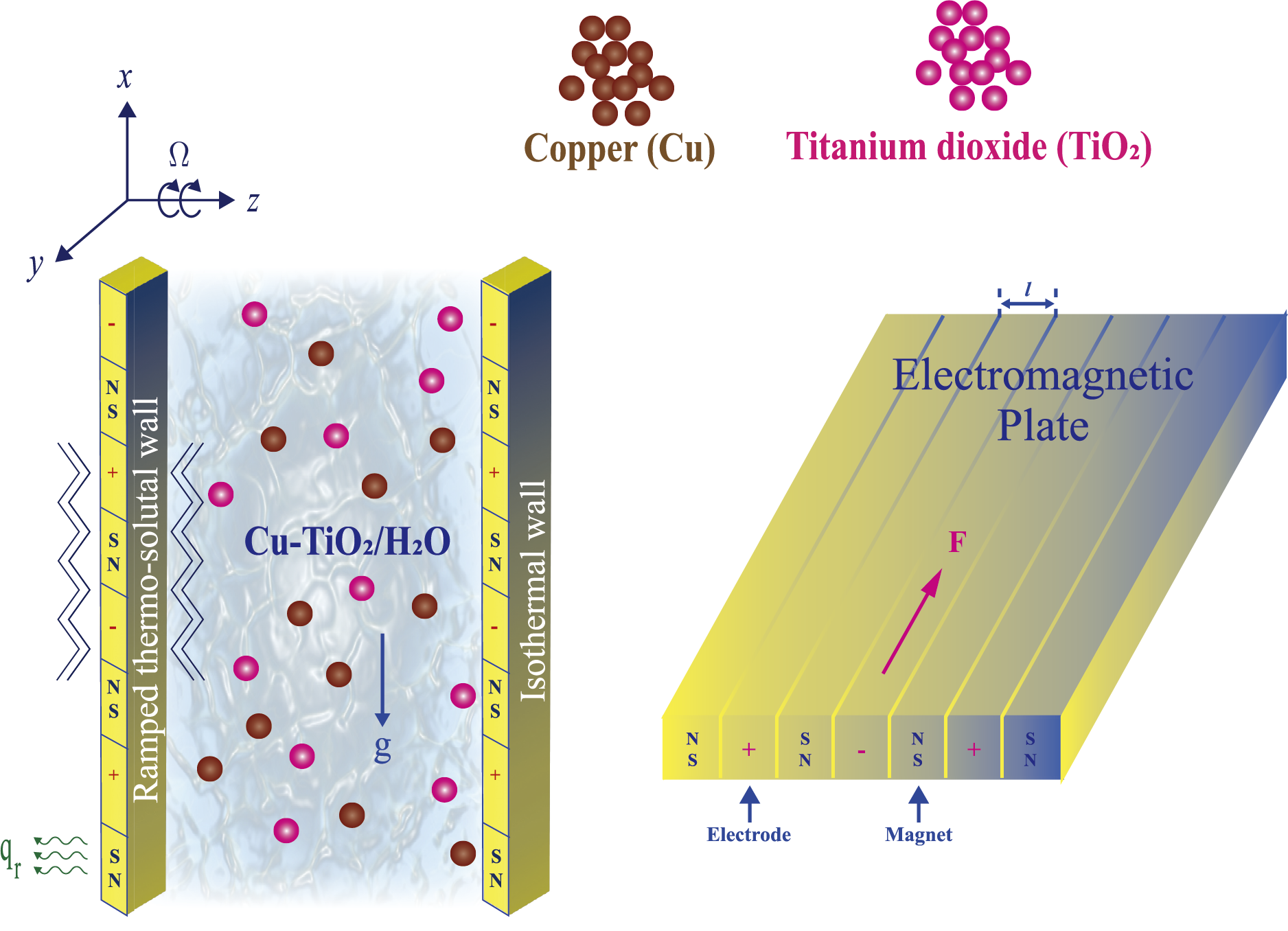
Figure 1: Physical configuration of flow
The formulation is constructed on the following physical premises:
• The working medium is a single-phase hybrid nanofluid composed of uniformly dispersed Cu and TiO2 NPs in water. The suspension is considered incompressible, weakly conductive, and chemically reactive.
• Flow is laminar, unsteady, and two-dimensional.
• The isotropic and homogeneous porous matrix filling the domain is assumed.
• Nanoparticle diameters are much smaller than the typical pore scale, thereby avoiding pore blockage or slip effects at the fluid-solid interface.
• A first-order homogeneous chemical reaction takes place, with a rate proportional to the local solute concentration.
• Thermal equilibrium holds among the fluid, nanoparticles, and porous medium throughout the tunnel.
• Owing to the infinite extent of the plates, variations occur only in the transverse coordinate
Using the Boussinesq approximation, the coupled momentum, energy, and species equations are formulated for a weakly conducting hybrid nanofluid in a rotating Riga tunnel, accounting for porous resistance, electromagnetic forcing, Hall and ion-slip effects, radiation, and chemical reaction [45,63]:
In Eqs. (1) and (2), the terms
The corresponding initial and boundary conditions (IBCs) are [63]:
The Rosseland approximation [25] offers a tractable method for modeling radiative heat transfer in optically thick media, where radiation transport occurs primarily through absorption, scattering, and re-emission of photons. This approach is particularly applicable when the mean free path of photons is significantly smaller than the characteristic length scale of the temperature gradient, allowing the radiative flux to be expressed in a diffusion-like form. While widely used in astrophysical and high-temperature engineering applications, such as stellar interiors and thermally insulated enclosures, its accuracy diminishes in optically thin or semi-transparent media with sharp thermal gradients. Under the Rosseland diffusion approximation, the radiative heat flux
where
To facilitate mathematical treatment and ensure linearity in the governing energy equation, the term
to
Substituting into Eq. (3), we obtain:
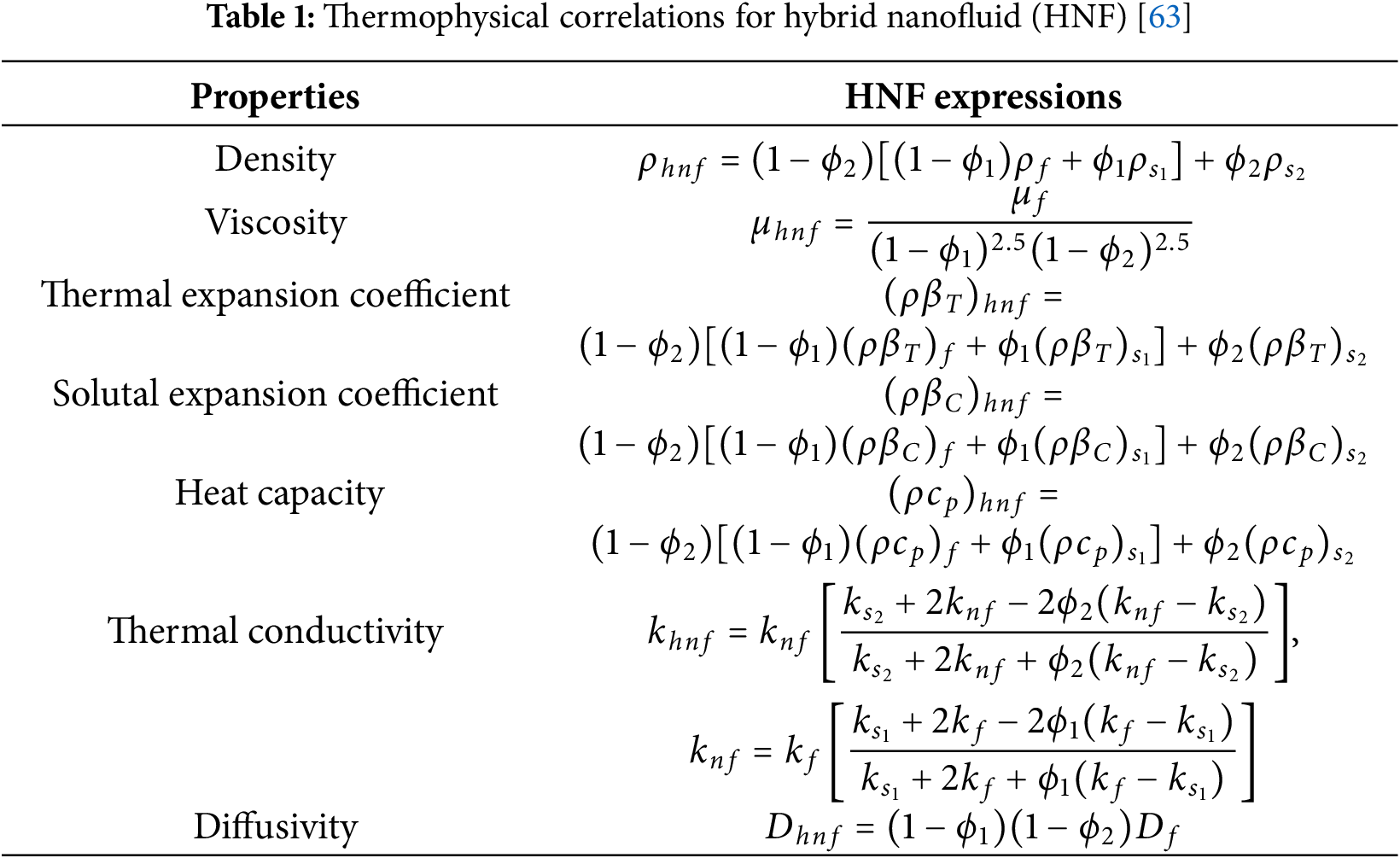
2.4 Thermo-Physical Correlation and Properties of Hybrid Nanofluid (HNF)
The macroscopic behavior of a hybrid nanofluid (HNF) is governed by its effective thermo-physical attributes, which are obtained through standard mixture-based correlations. The key quantities considered include viscosity, density, heat capacity, coefficients of thermal and solutal expansion, and thermal conductivity. A summary of the adopted formulations is reported in Table 1. In the present case, the suspension is prepared by combining copper (Cu) and titanium dioxide (TiO2) nanoparticles within water, serving as the host fluid. The volumetric share of Cu is represented by
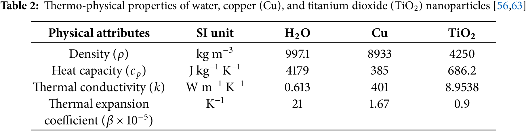
For completeness, Table 2 lists the inherent thermophysical constants of the three constituents (Cu, TiO2, and water). These parameters form the baseline for calculating the effective properties of the nanofluid and hybrid nanofluid models applied in this study.
To facilitate the mathematical analysis, the governing equations are transformed into their dimensionless form by introducing appropriate non-dimensional variables. This non-dimensionalization simplifies the physical interpretation of the system parameters and reduces the number of governing variables. The following dimensionless quantities are employed, as adopted in recent studies [56,63]:
Considering (10), the dimensionless versions of Eqs. (1), (2), (4), and (9) can be succinctly expressed as follows:
where the non-dimensional parameters are:
The dimensionless IBCs are:
where
It is advantageous to consolidate Eqs. (11) and (12) into a single comprehensive equation. This is accomplished by initially multiplying Eq. (12) by
where
The IBCs for (
The Laplace Transform (LT) is an effective analytical method for solving linear differential equations, particularly in time-dependent and dynamic systems. Its strength lies in converting complex time-domain problems into simpler algebraic forms in the Laplace domain, especially through its linearity and ability to transform convolutions into multiplications. This makes LT especially suitable for initial- and boundary-value problems in linear time-invariant systems.
In the present study, the LT method is employed to obtain semi-analytical solutions for the governing Eqs. (13), (14) and (16), subject to the initial and boundary conditions given in (15). The corresponding Laplace-transformed formulations are derived as follows [63]:
where
The corresponding BCs for
Applying the boundary conditions (21), the solution to Eqs. (18)–(20) is formulated in the following manner:
where expressions
By applying the inverse Laplace Transforms to Eqs. (18)–(20), the analytical expressions for the concentration, temperature, and velocity distributions within the Riga tunnel are derived. These closed-form solutions are presented below and follow the methodologies outlined in [63]:
where the functions
Moreover, expressions
Eq. (27) represents the unified expression for flow field of an electrically conductive and thermally radiative hybrid nanofluid confined between two vertically extended infinite Riga plates in an intense electromagnetic rotational framework, invoking the existence of Hall and ion-slip currents, and occurrence of stepped up wall temperature and concentration. On separating into a real and imaginary parts one can easily obtain the velocity components (
The evaluation of key engineering parameters, such as shear stress, heat transfer rate, and mass transfer rate is crucial for a wide range of industrial and mechanical processes. These quantities directly influence thermal management, fluid transport efficiency, and chemical reactivity at boundaries, thereby playing a central role in optimizing operational performance. Accurate prediction and control of these parameters are essential not only for ensuring process stability and energy efficiency but also for enhancing the reliability, safety, and durability of engineering systems. Consequently, their rigorous assessment is indispensable during both the design and operational stages of technological applications.
2.7.1 Heat and Mass Transfer Rates
The nondimensional heat and mass transfer rates at the left wall of the tunnel (
where
The non-dimensional shear stresses at the left wall of the tunnel (
where the functions
2.8 Solutions under UWT and UWC Conditions
Under uniform wall temperature (UWT) and uniform wall concentration (UWC) conditions, the dimensionless boundary initial conditions in Eq. (21) are modified by setting
where the expressions of the known functions
For UWT and UWC situations, the dimensionless MTR
where the expressions of the known functions
In order to understand the effectiveness of stepped up wall temperature and concentration (RWTC, UWTC) conditions. A comparative analysis is conducted sketchily on the (HNF, NF) flows within a moving thermal Riga tunnel.
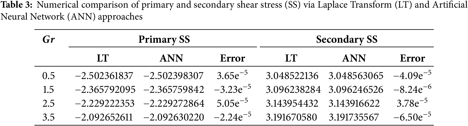
In the limiting case, where the effects of rotation, Hall, and ion-slip currents are neglected, the present analytical formulation precisely reduces to the benchmark solutions reported by Ali et al. [63] (see Fig. 2). This convergence not only verifies the mathematical consistency and accuracy of the current analytical model but also extends the theoretical framework of electromagnetically actuated hybrid nanofluid dynamics to more complex rotating environments incorporating Hall and ion-slip phenomena. Moreover, the comparative results presented in Table 3 reveal excellent concordance between the left-wall shear stress values computed using the Laplace Transform (LT) technique and those predicted by the Artificial Neural Network (ANN) model for both primary and secondary shear stress components. The observed discrepancies are minimal, with relative errors on the order of
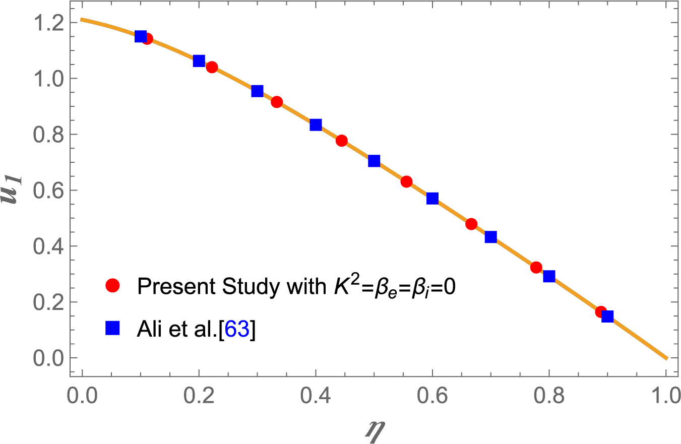
Figure 2: Comparison of velocity profile
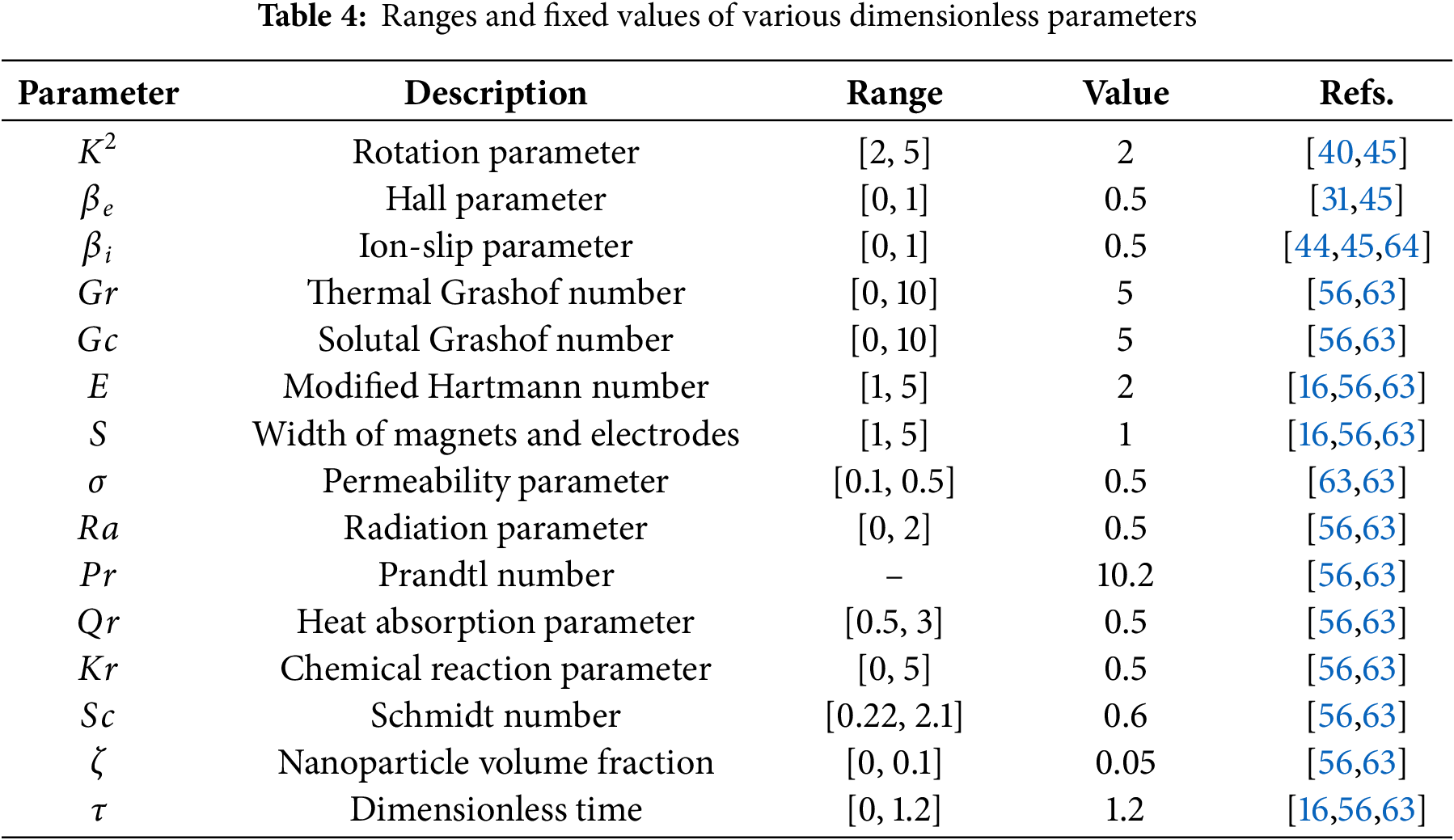
This section investigates the influence of key physical parameters on the essential flow features of the system. The numerical results, derived from comprehensive computational simulations, are presented in Figs. 3–29. These figures demonstrate how variations in thermal, geometric, and transport parameters affect fundamental flow fields and associated transport rates. The parameter ranges employed in this study are selected based on relevant literature and are systematically summarized in Table 4. All graphical outputs have been generated using Mathematica, ensuring high numerical accuracy and clarity in visual representation. This analysis provides a detailed understanding of how individual and combined effects of critical parameters shape the fluid dynamics and transport phenomena, offering valuable physical insights into the behavior of the hybrid nanofluid system under various conditions.
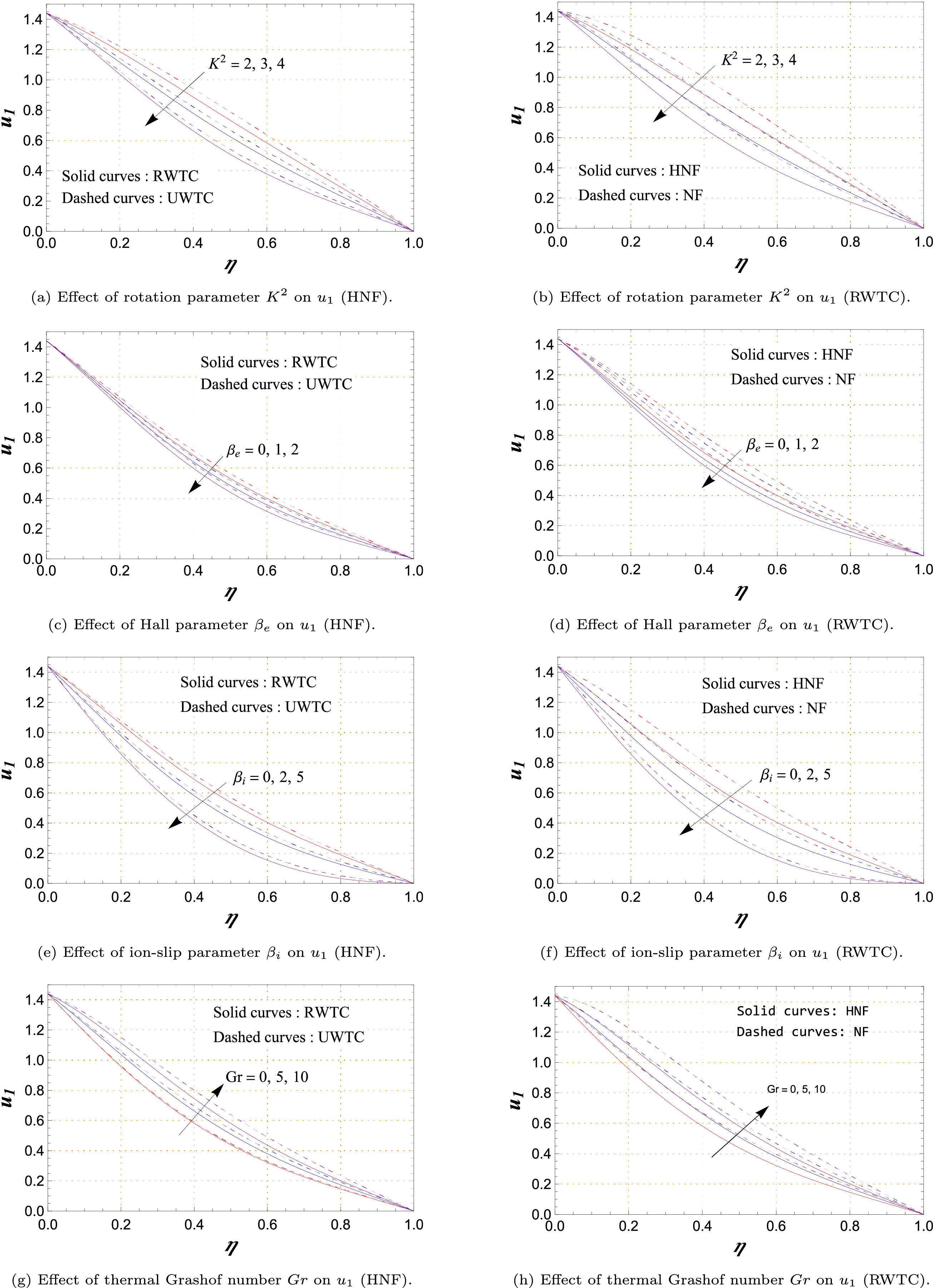
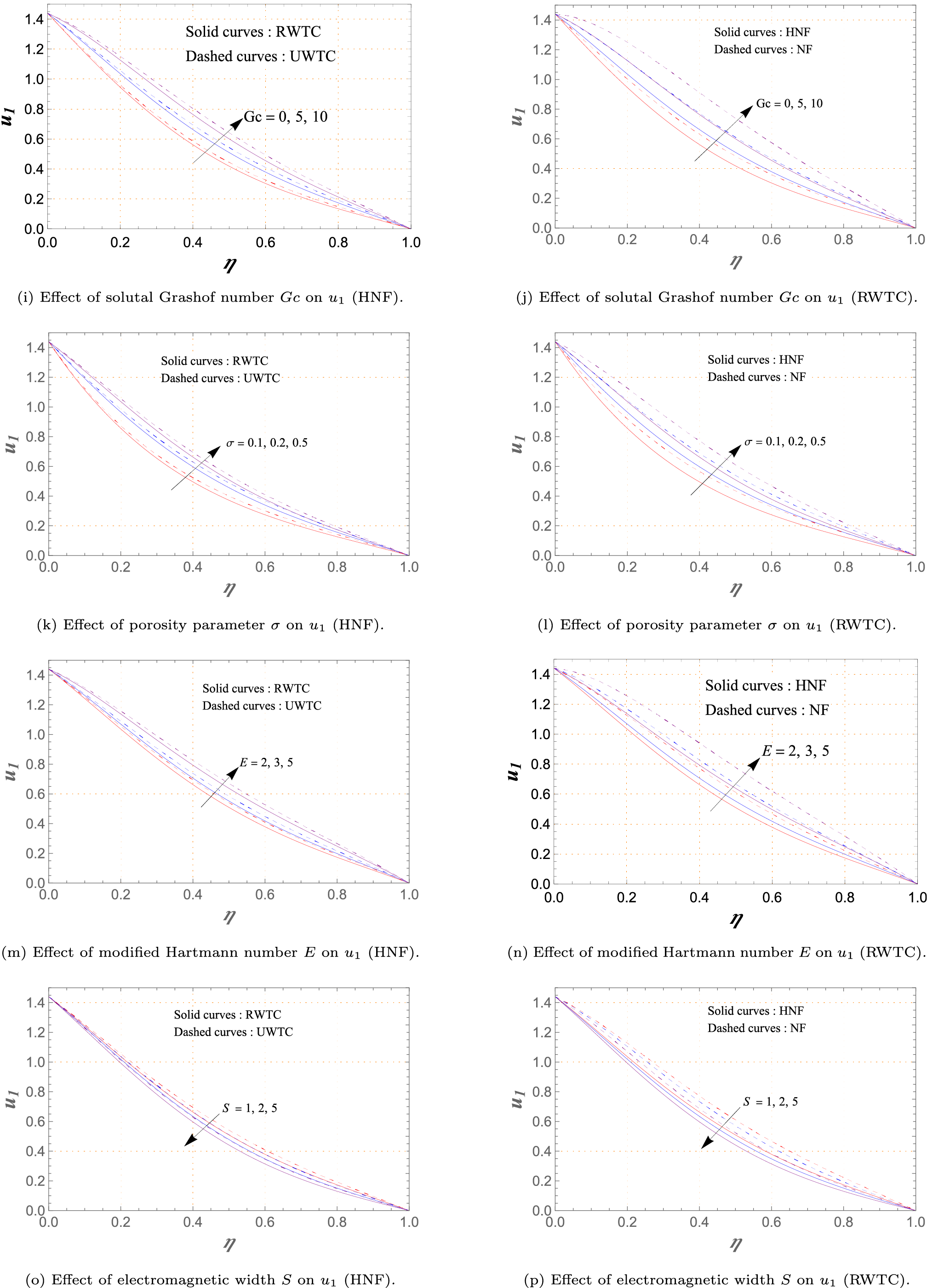
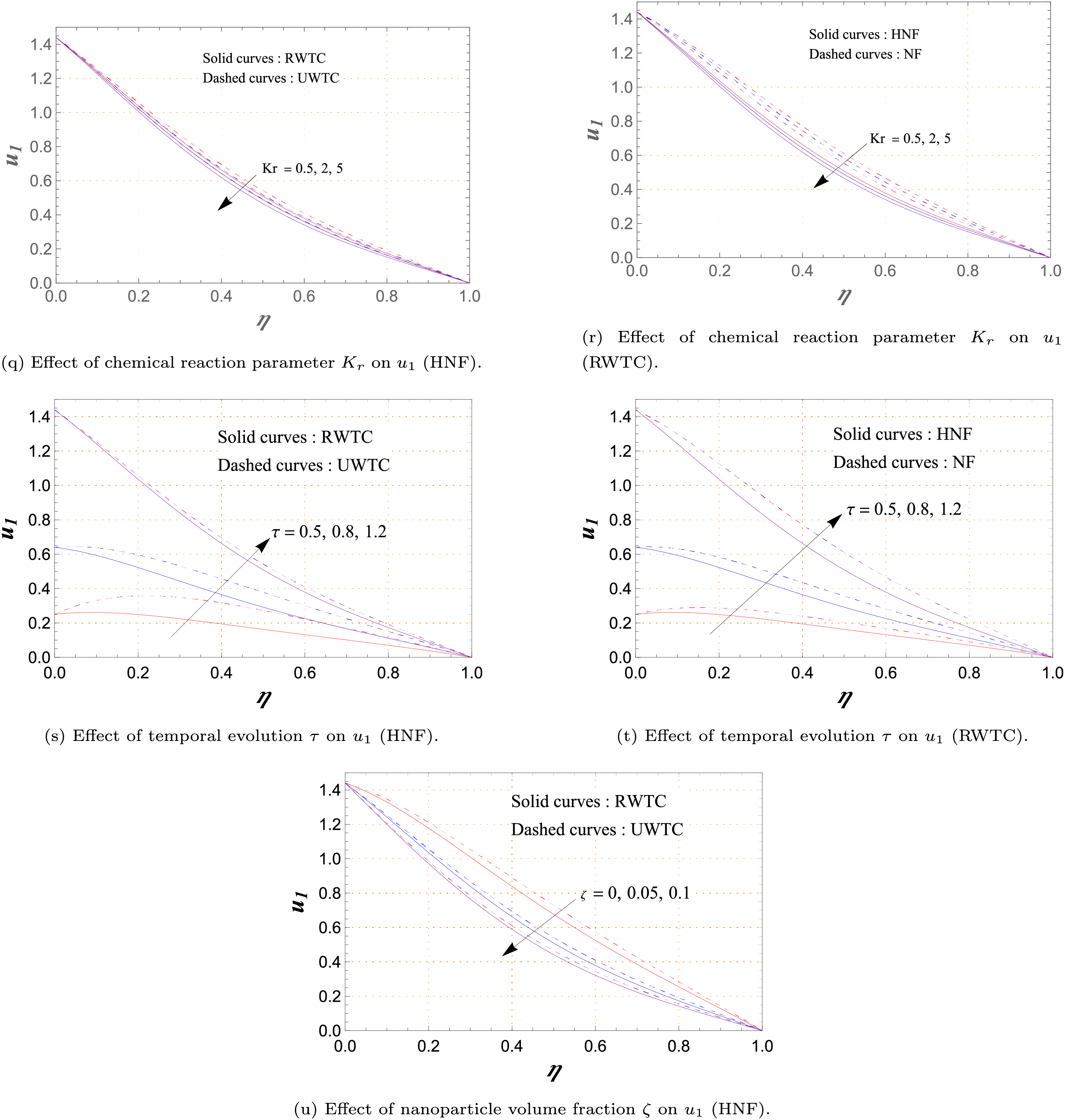
Figure 3: Variations of primary velocity
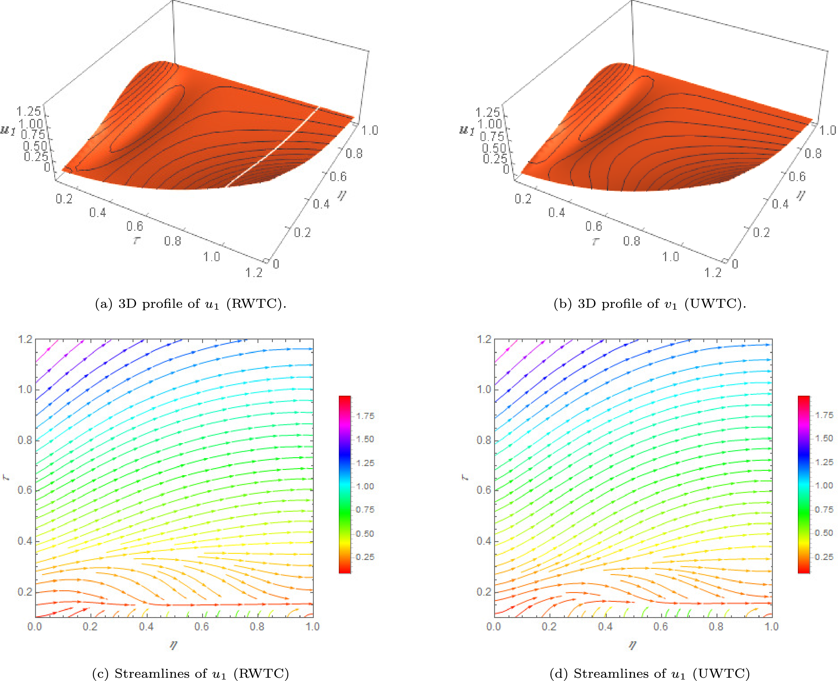
Figure 4: 3D visualization of the profile
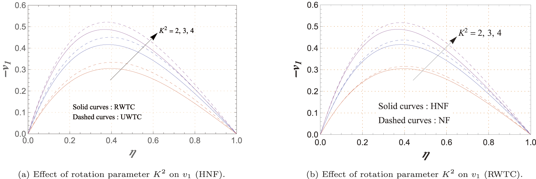
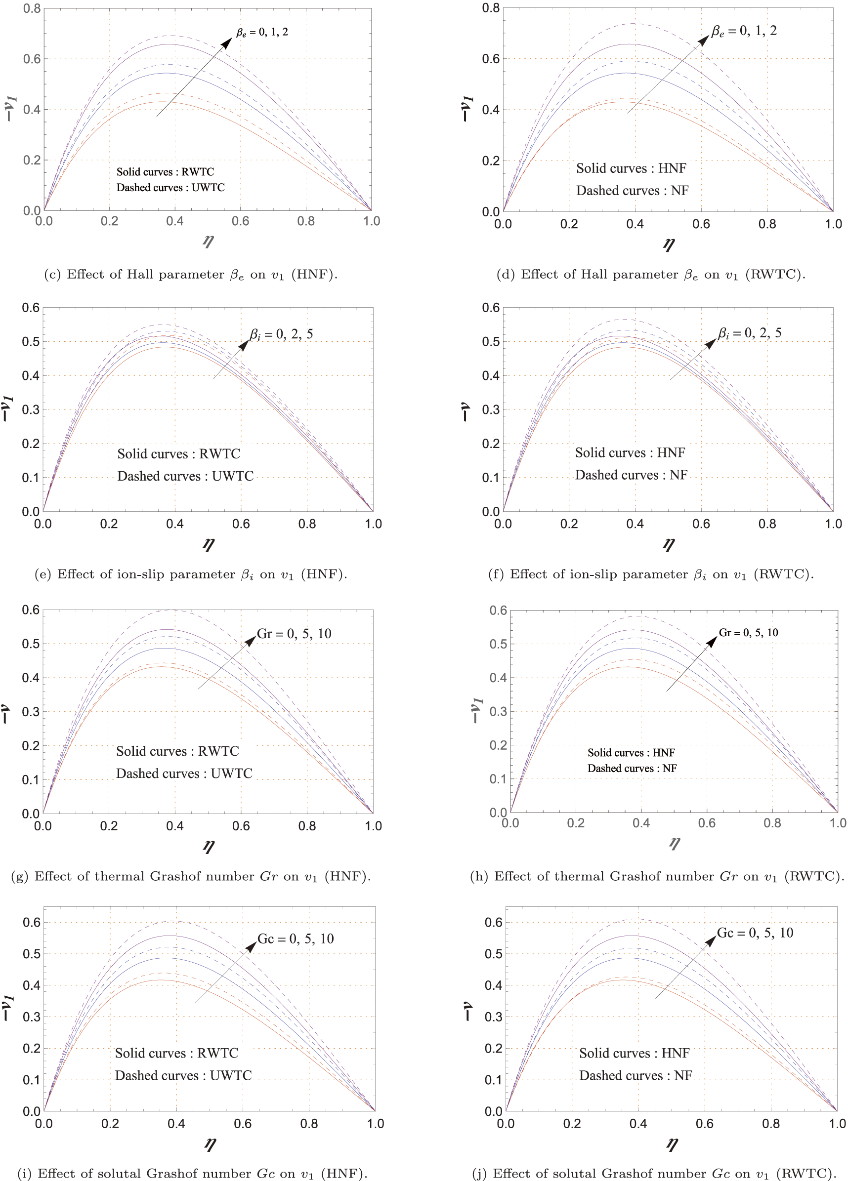
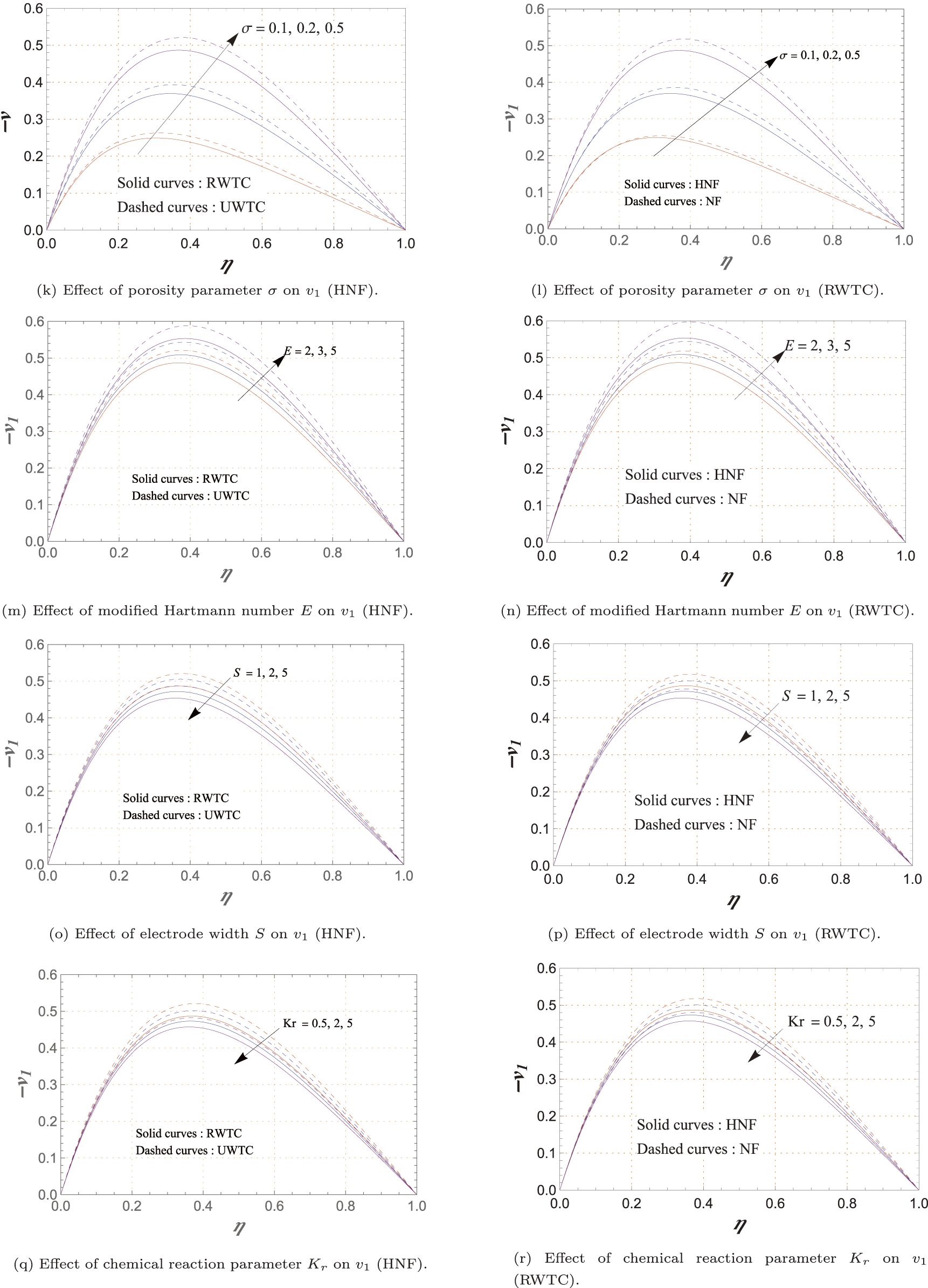
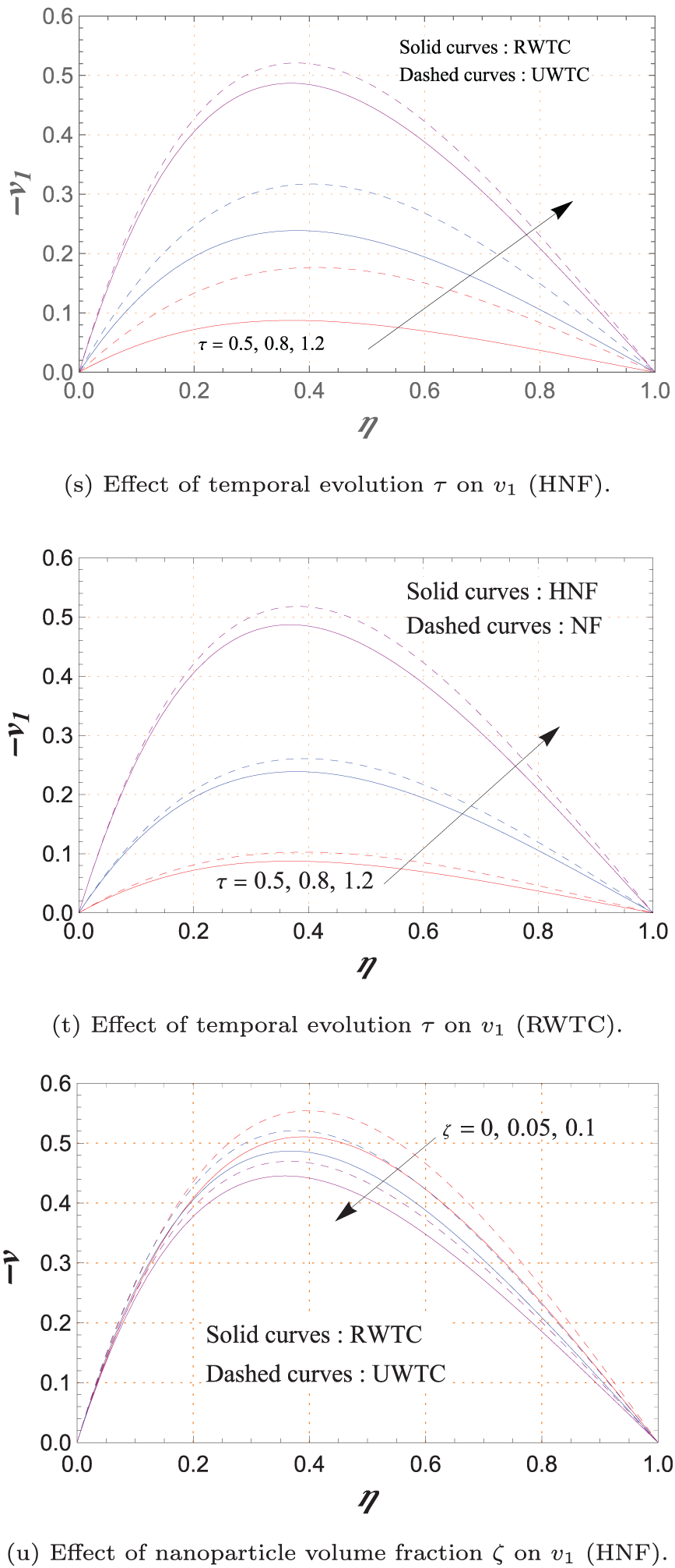
Figure 5: Variations of secondary velocity
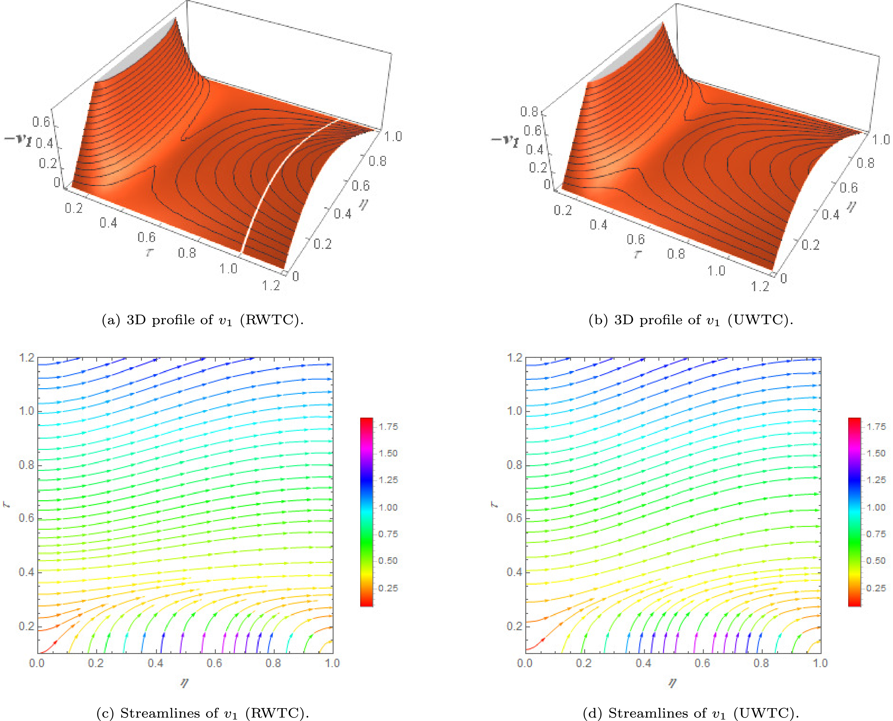
Figure 6: 3D visualization of secondary velocity
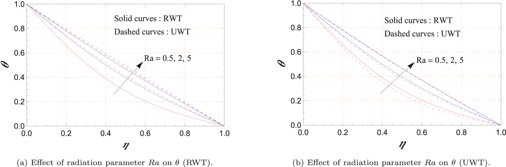
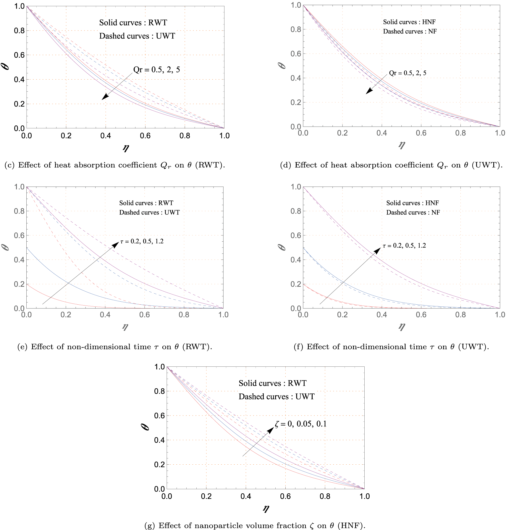
Figure 7: Variations of temperature profile
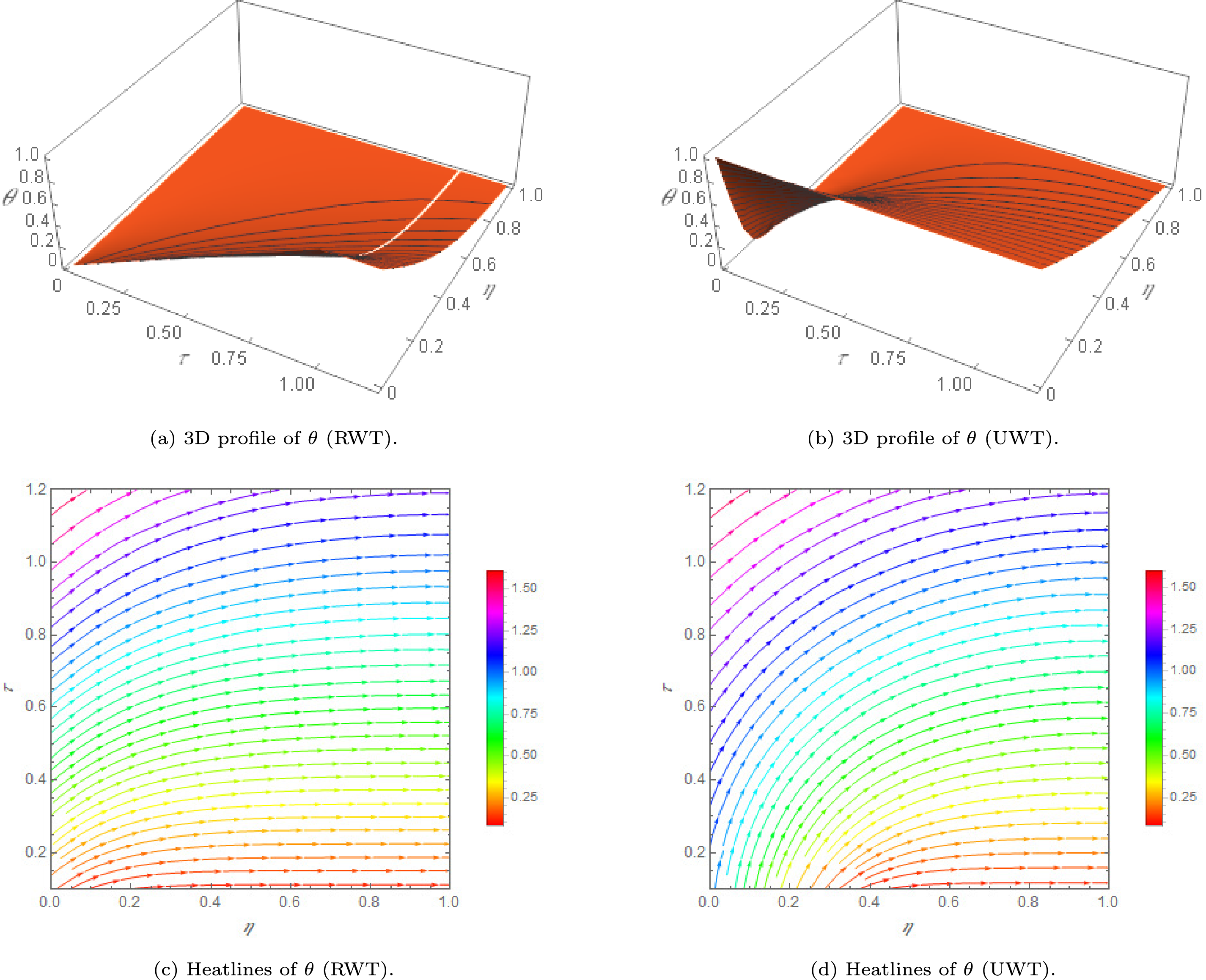
Figure 8: 3D visualization of temperature profile
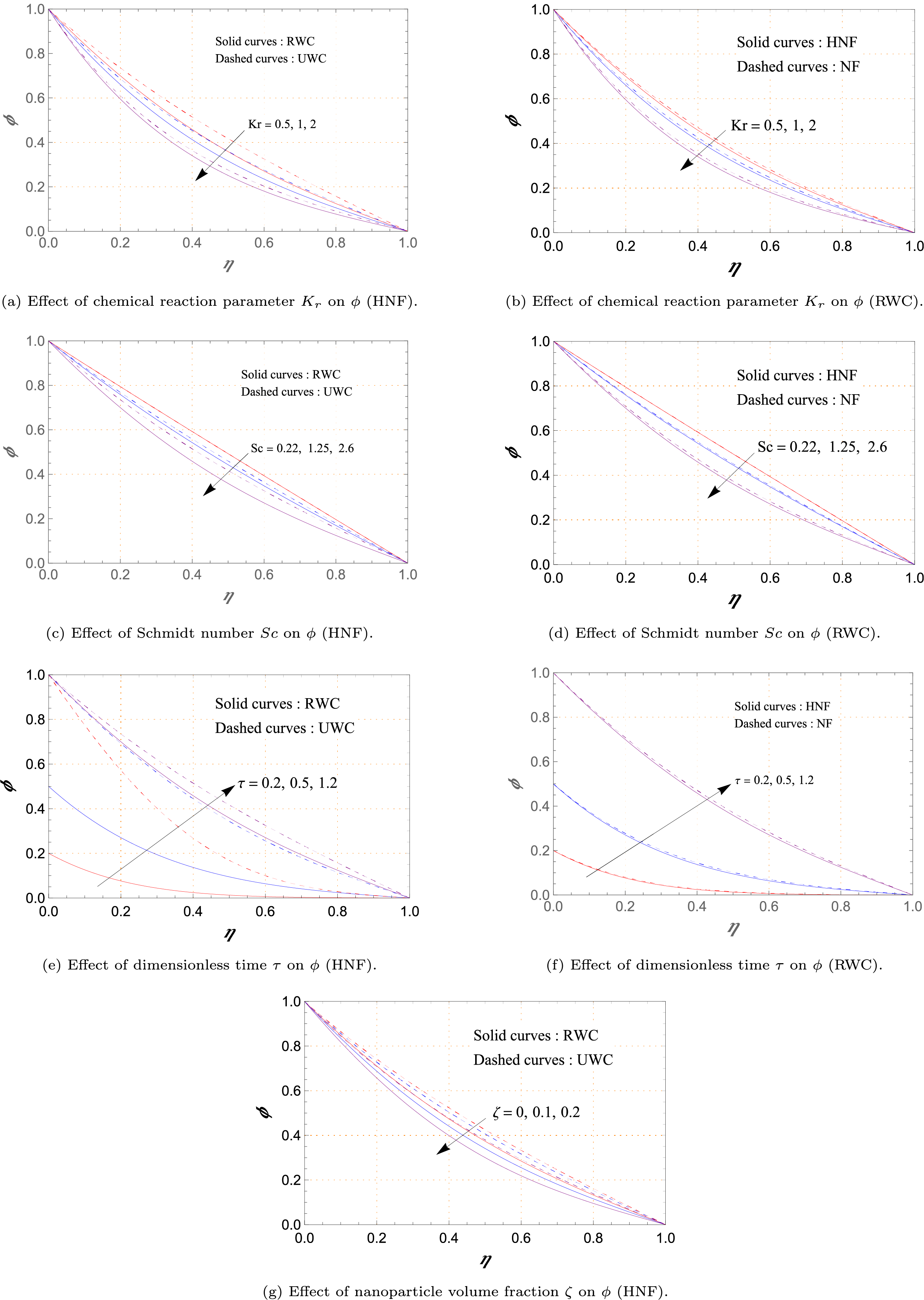
Figure 9: Variations of concentration profile
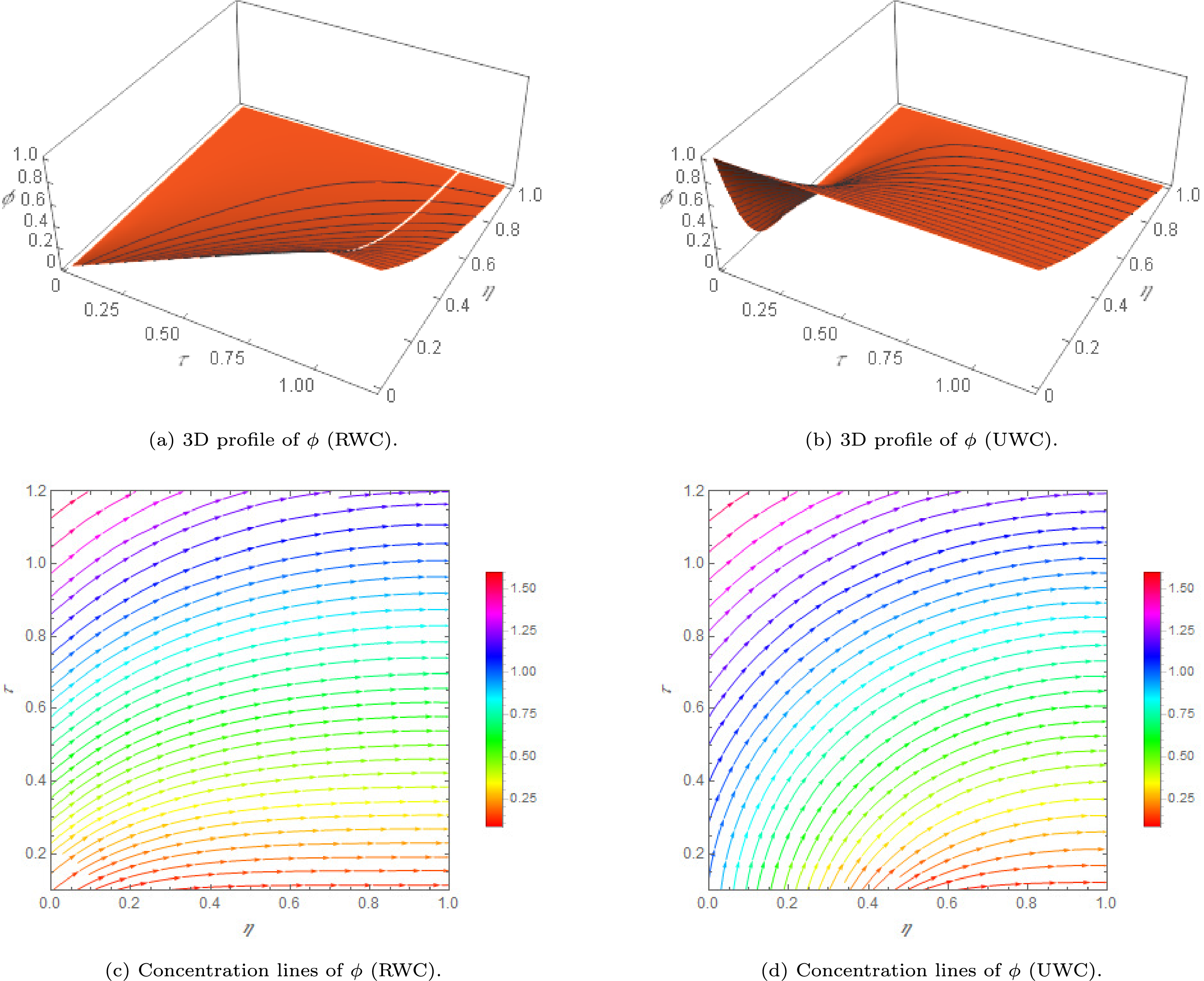
Figure 10: 3D visualization of the profile
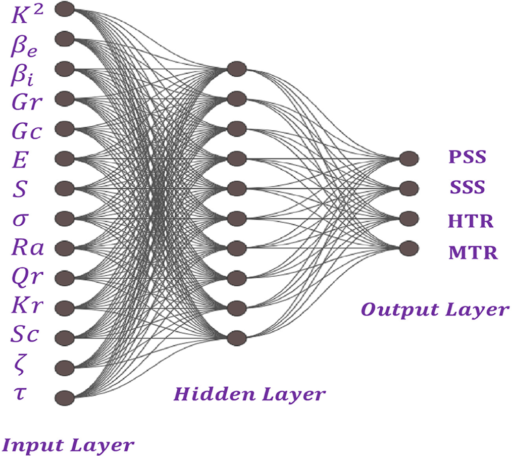
Figure 11: Schematic architecture of ANNs
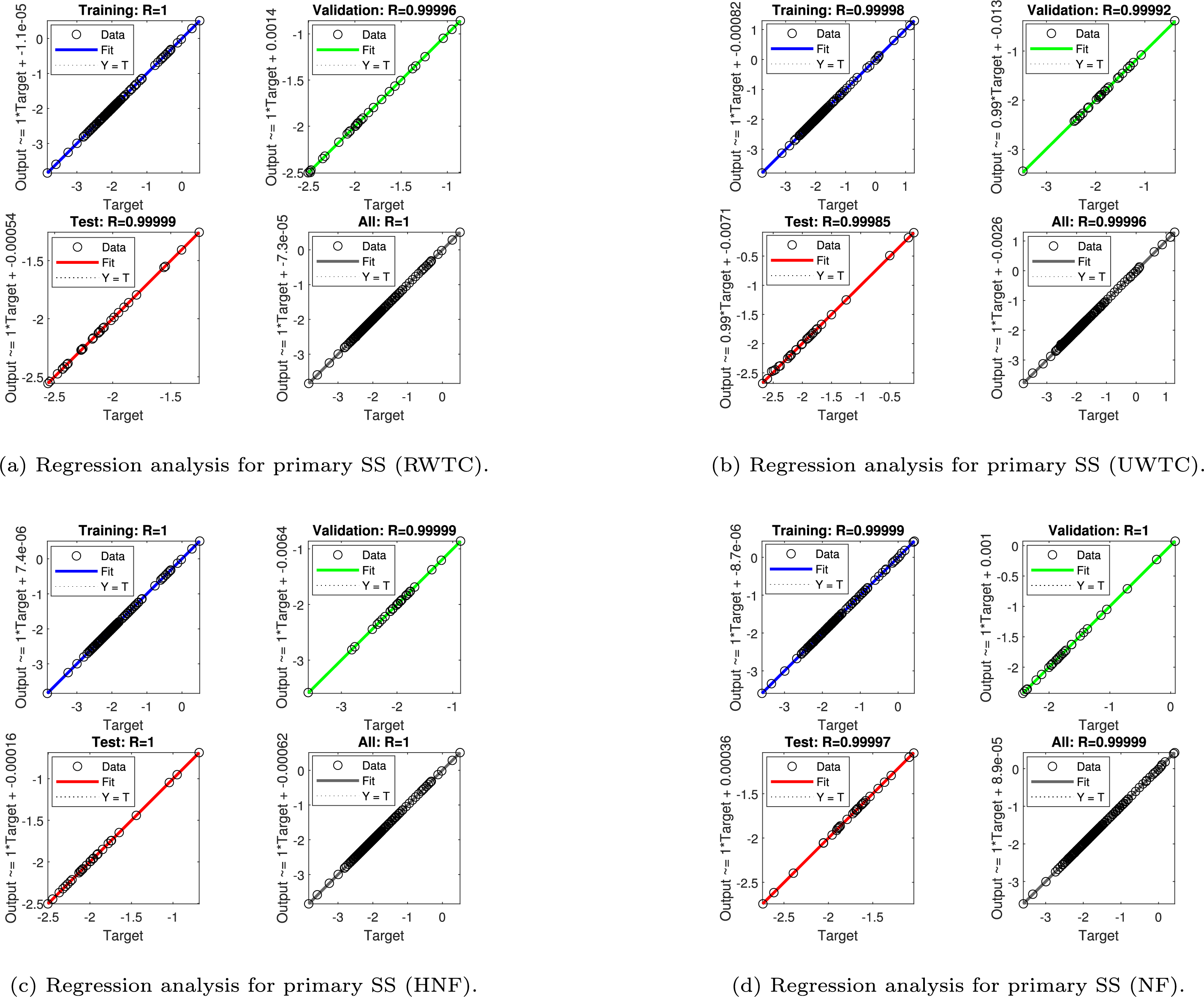
Figure 12: Regression analysis for primary shear stress (SS)
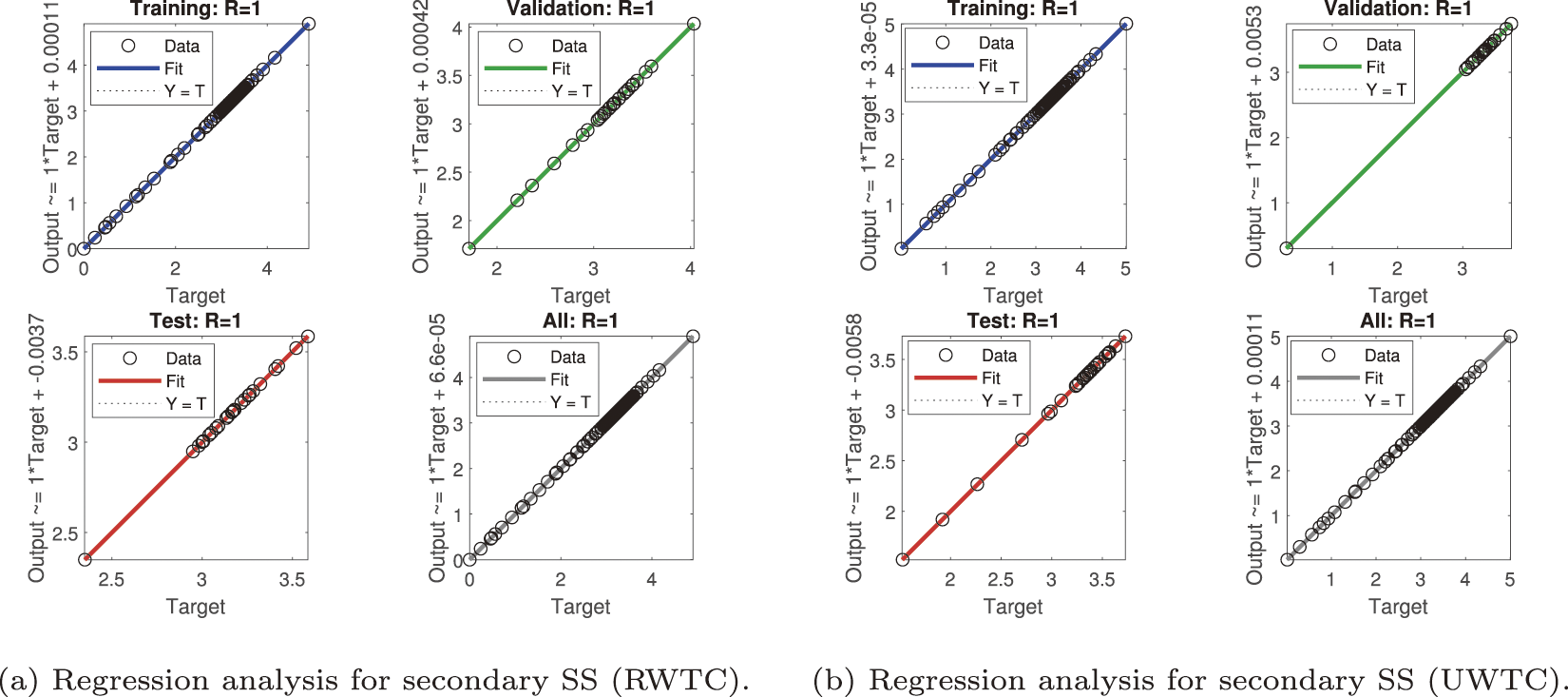
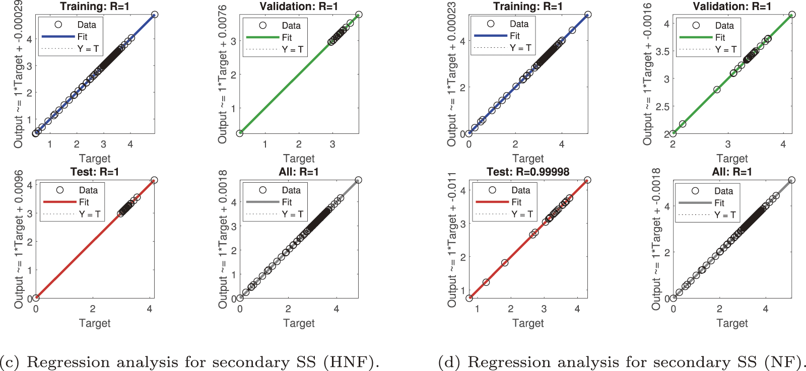
Figure 13: Regression analysis for secondary shear stress (SS)
Figure 14: Regression analysis for heat transfer rate (HTR)
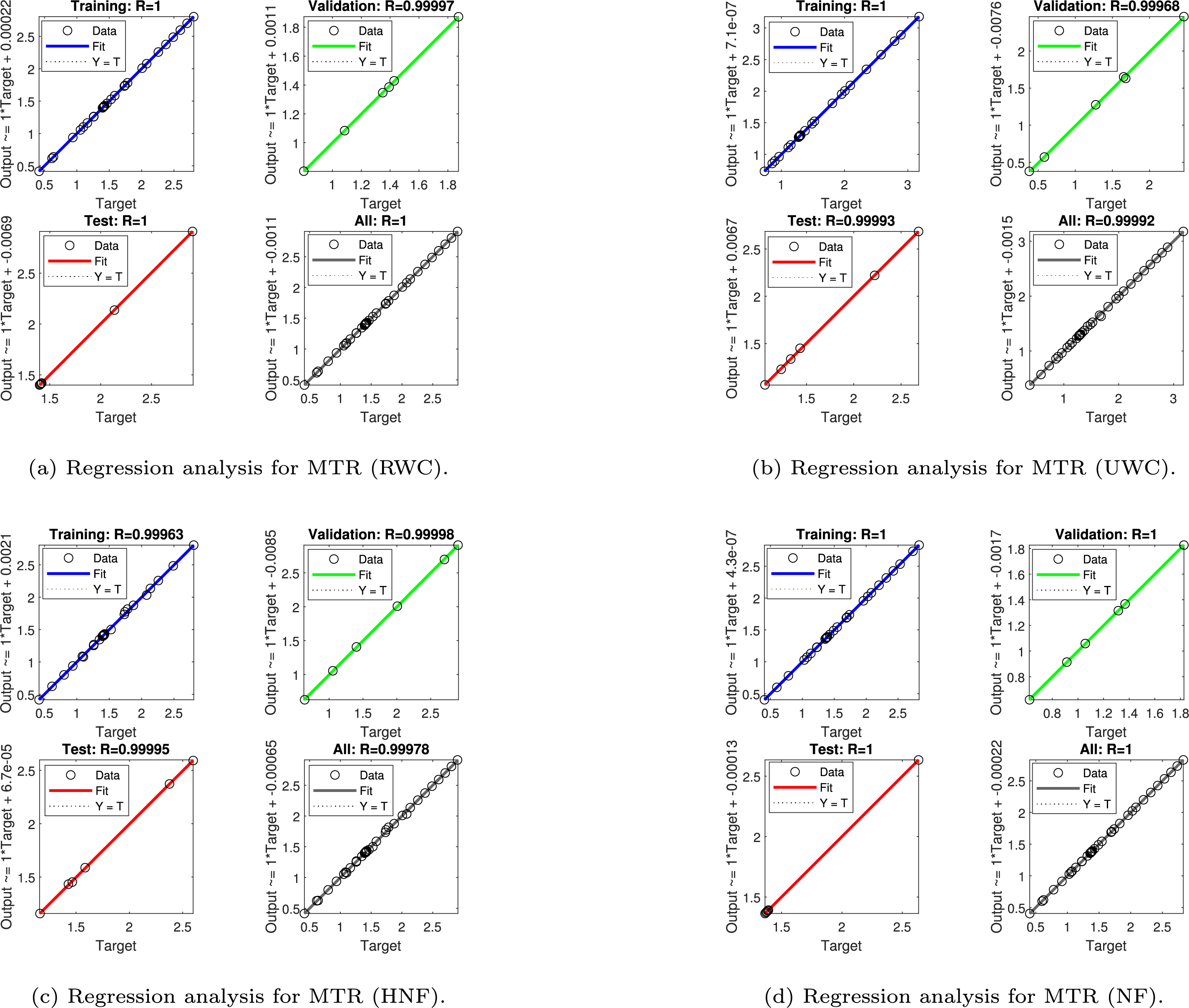
Figure 15: Regression analysis for mass transfer rate (MTR)
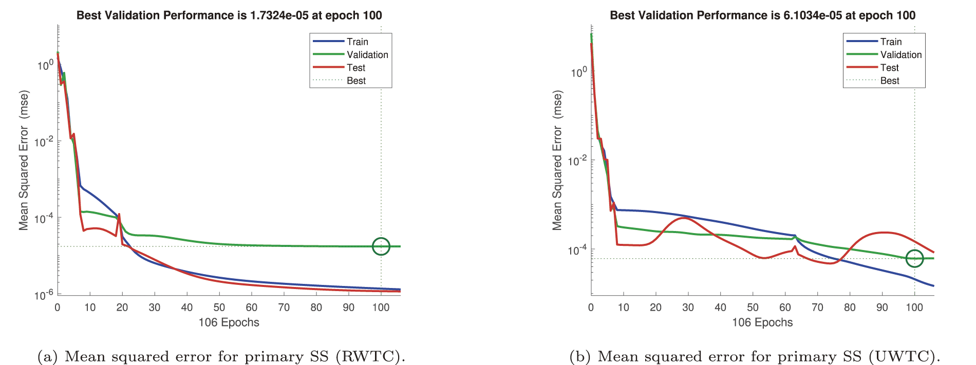
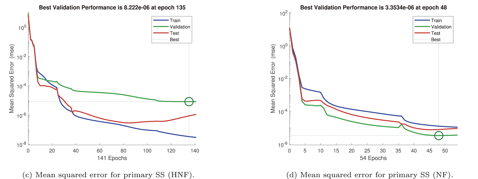
Figure 16: Mean squared error (MSE) for primary shear stress (SS)
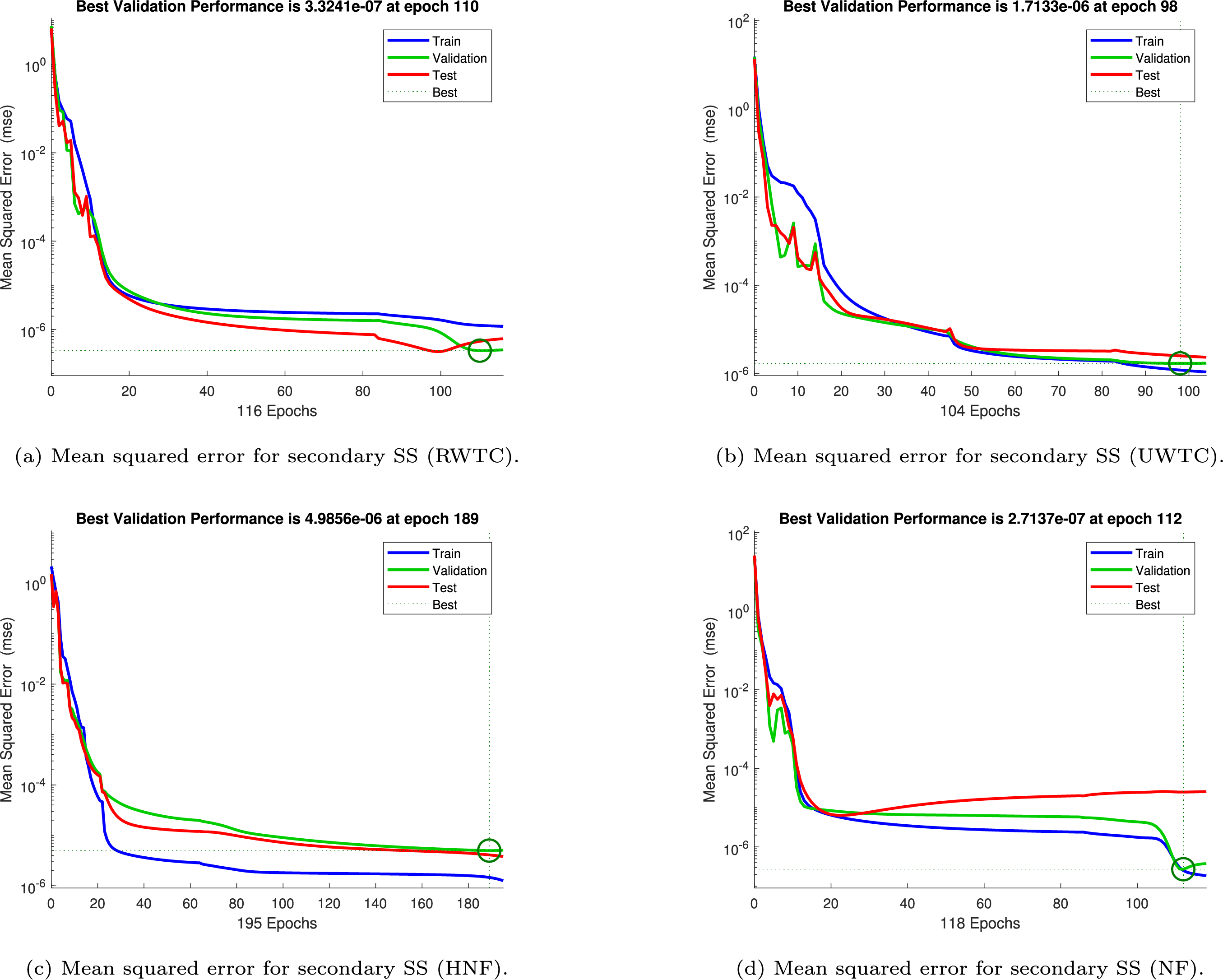
Figure 17: Mean squared error (MSE) for secondary shear stress (SS)
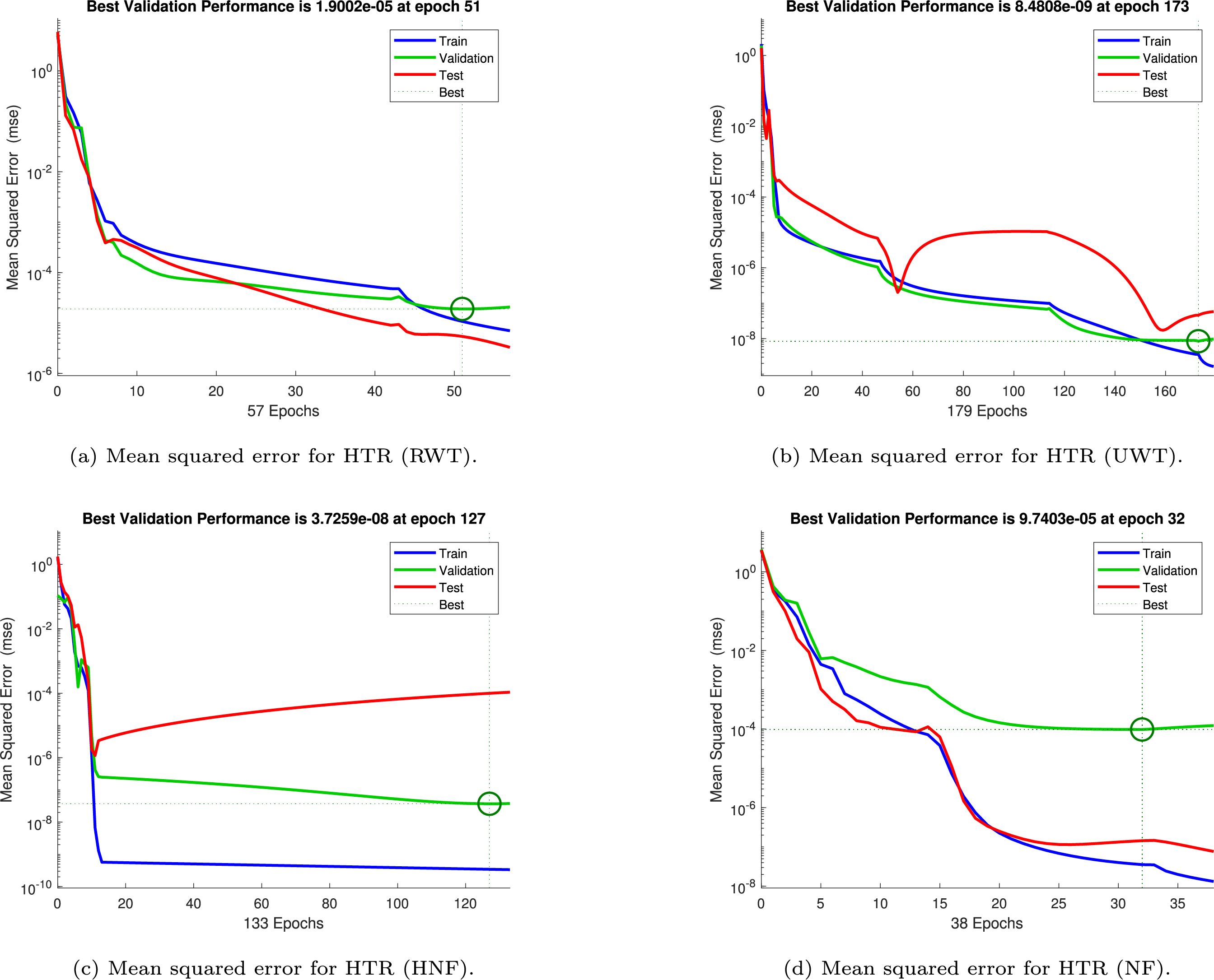
Figure 18: Mean squared error (MSE) for heat transfer rate (HTR)
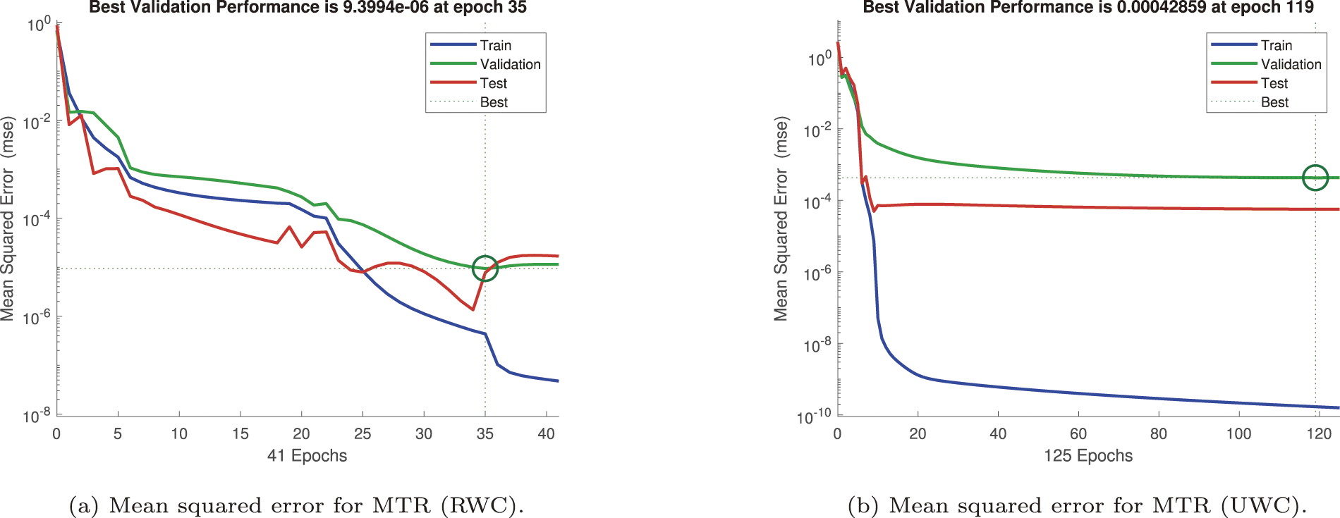
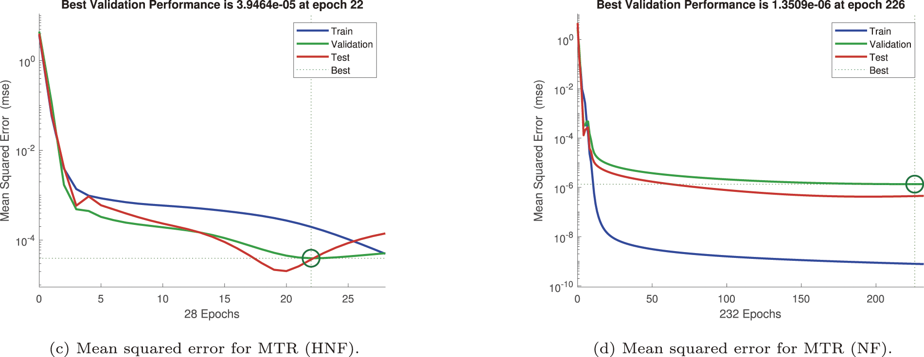
Figure 19: Mean squared error (MSE) for mass transfer rate (MTR)
Figure 20: State evolution of primary shear stress (SS)
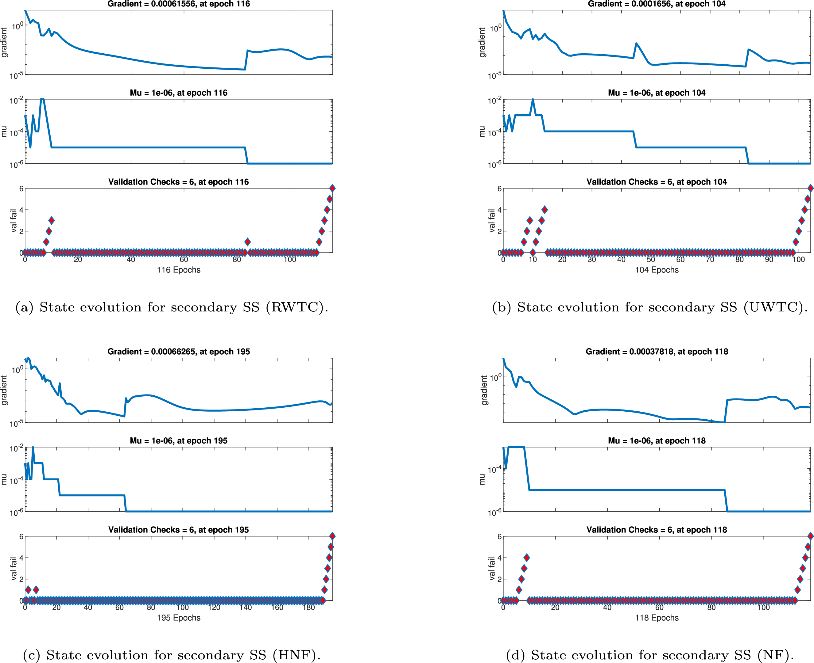
Figure 21: State evolution of secondary shear stress (SS)
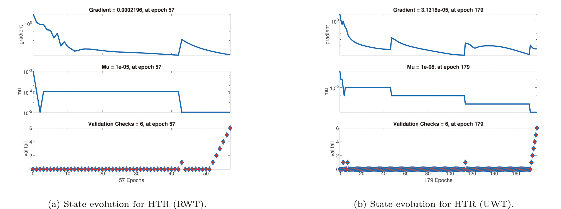
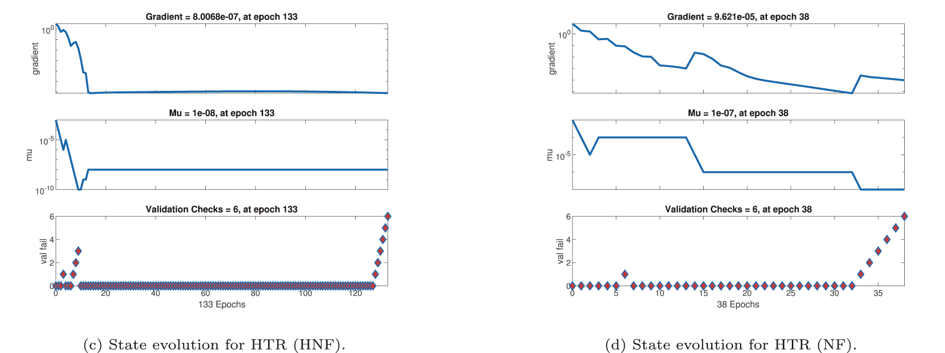
Figure 22: State evolution of heat transfer rate (HTR)
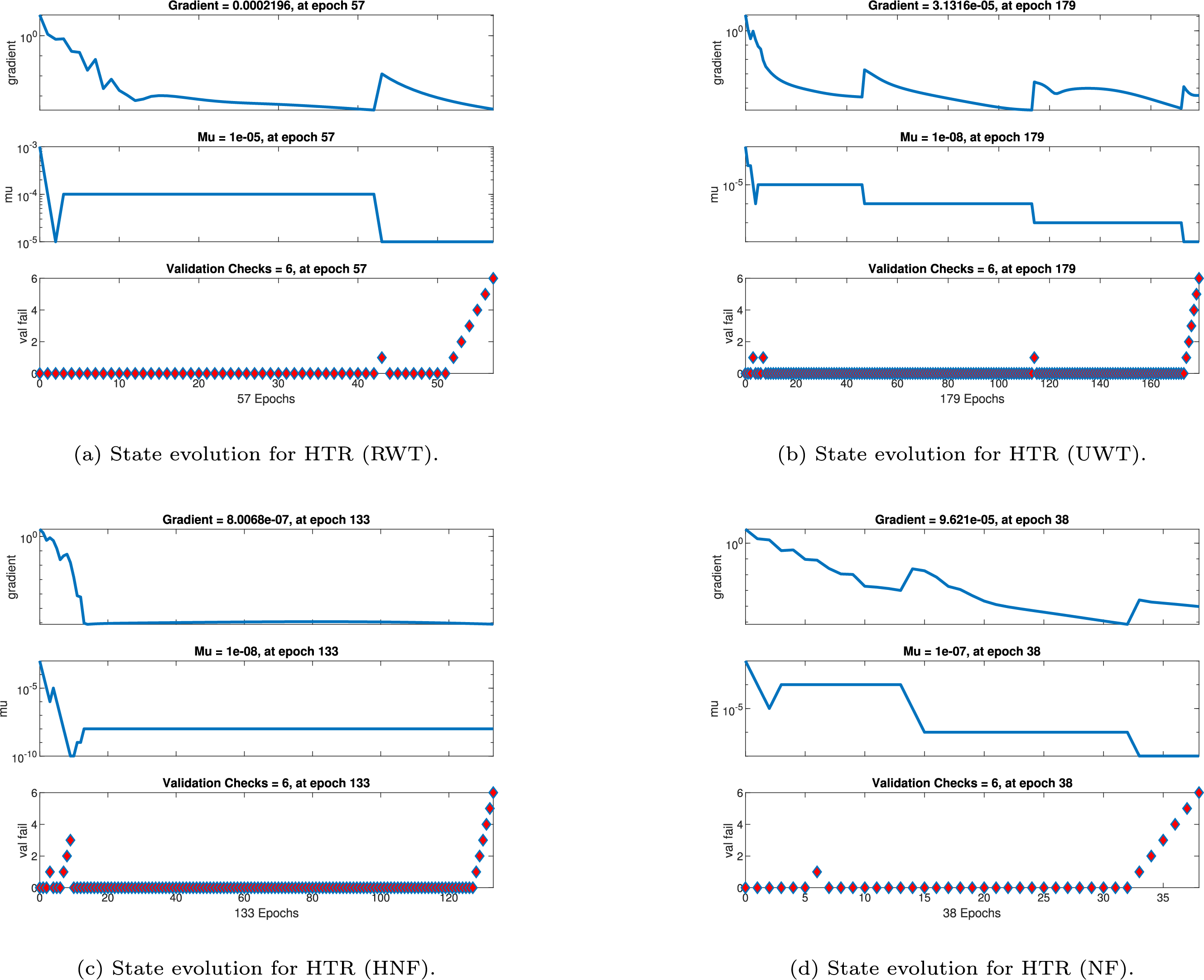
Figure 23: State evolution of mass transfer rate (MTR)
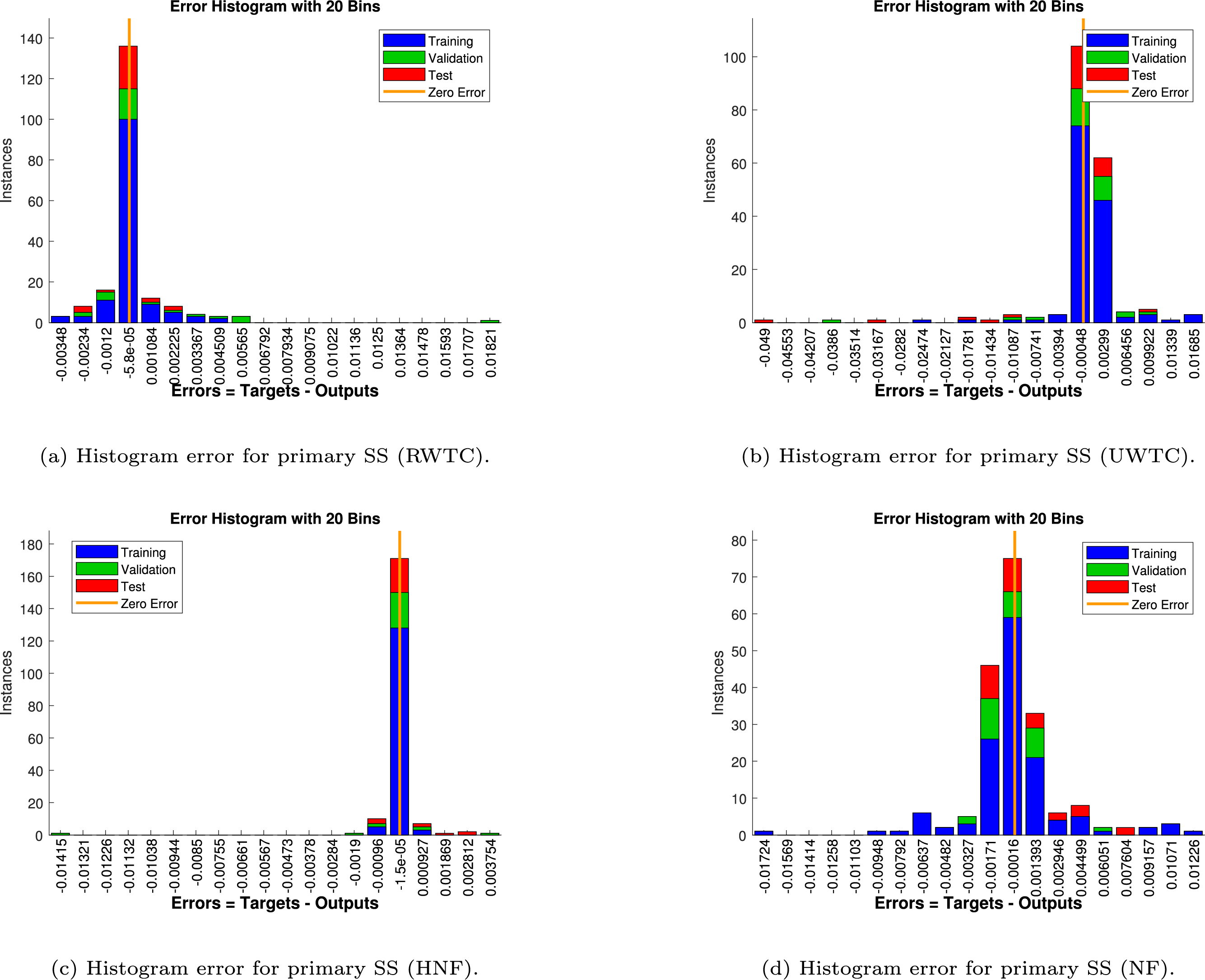
Figure 24: Histogram error analysis for primary shear stress (SS)
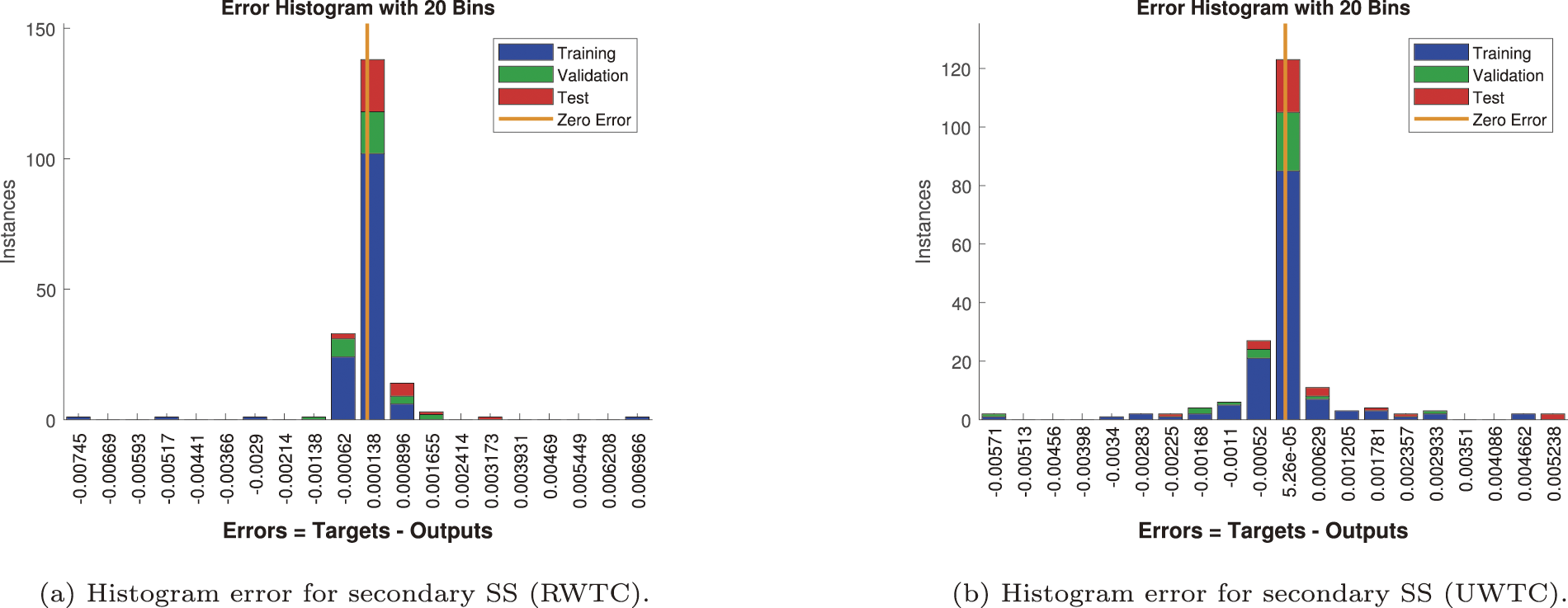
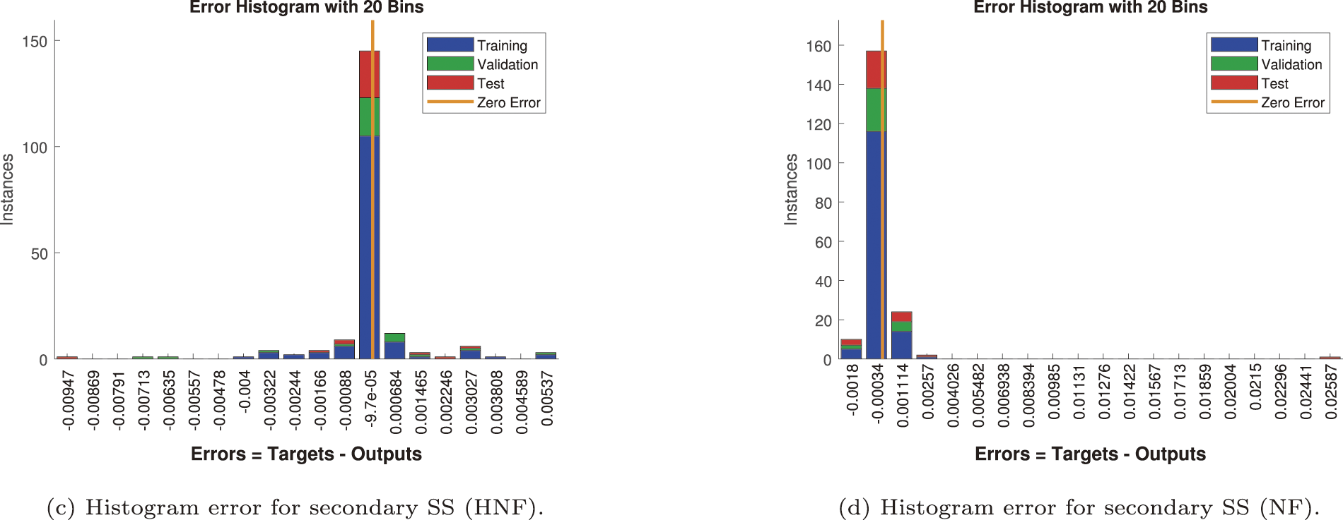
Figure 25: Histogram error analysis for secondary shear stress (SS)
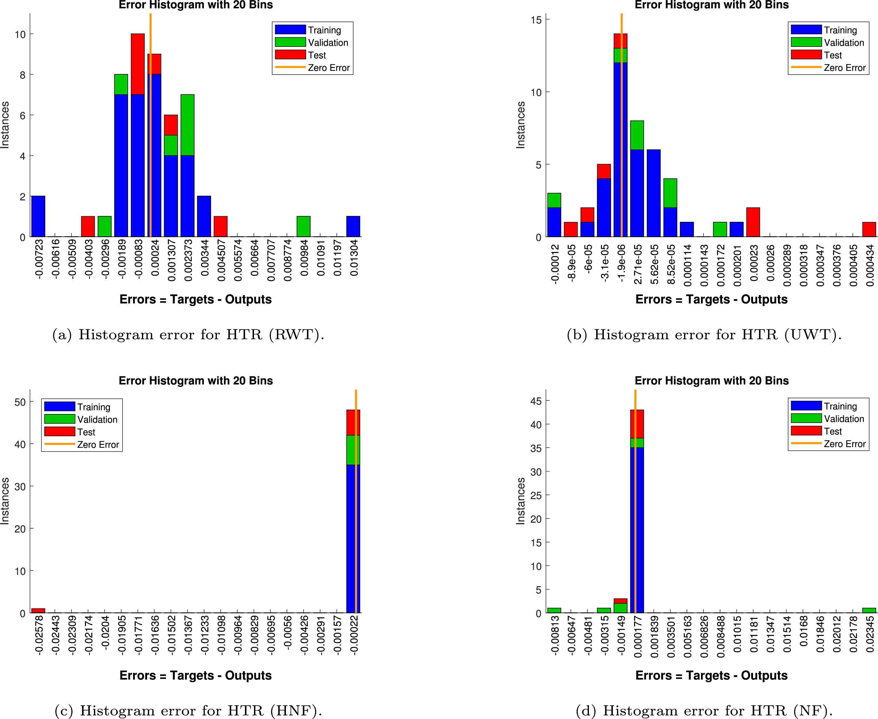
Figure 26: Histogram error analysis for heat transfer rate (HTR)
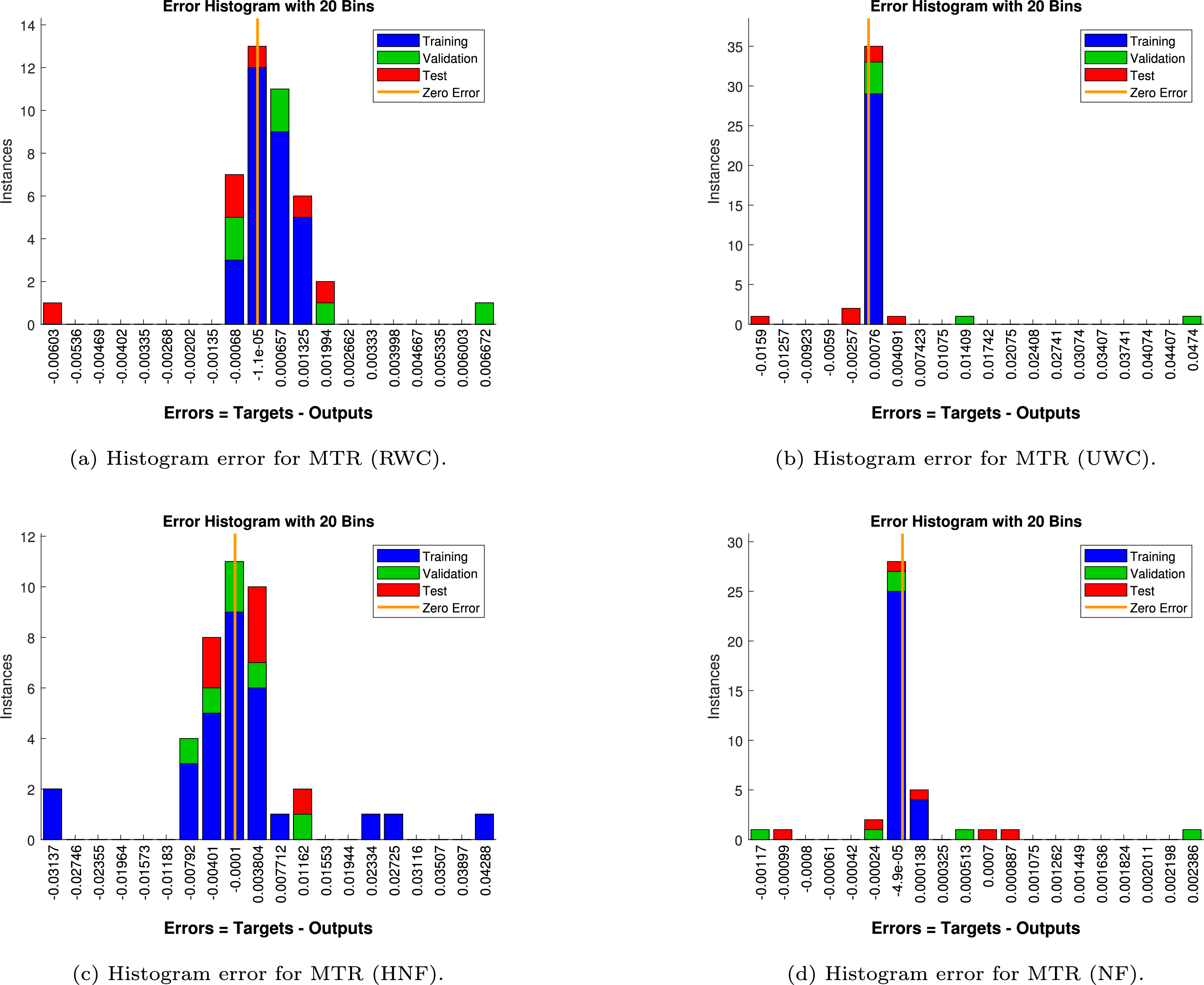
Figure 27: Histogram error analysis for mass transfer rate (MTR)
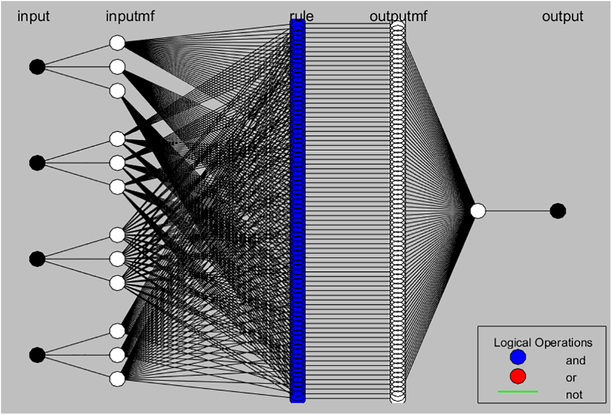
Figure 28: Adaptive Neuro-Fuzzy Inference System (ANFIS) training performance
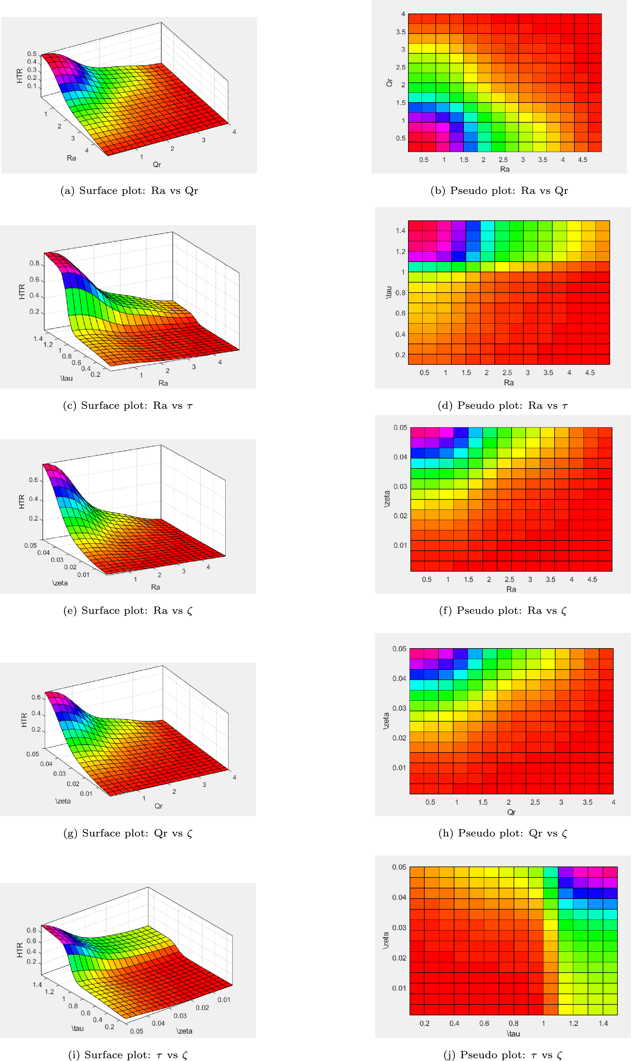
Figure 29: Surface and pseudo plots showing the influence of different pairs of parameters on HTR
4.1 Main Flow (Primary Velocity Profiles)
Fig. 3a–u presents the response of the non-dimensional velocity component
In Fig. 3a,b, the rotation parameter
Fig. 3c,d highlights the influence of the Hall parameter
The variation of
Fig. 3g,h reports the influence of the thermal Grashof number
The solutal Grashof number
Fig. 3k,l depicts the effect of the porosity parameter
The modified Hartmann number
Fig. 3o,p shows the role of
The impact of the chemical reaction parameter
Fig. 3s,t captures the temporal development of
Panels Fig. 3b,d,f,h,j,l,n,p,r,t provide side-by-side comparisons of NF and HNF. The hybrid fluid consistently yields a lower
Fig. 3a,c,e,g,i,k,m,o,q,s compares RWTC with UWTC boundary conditions. In all scenarios, RWTC produces a smaller velocity. Non-uniform wall heating and solutal ramping introduce gradients in viscosity and density, increasing resistance to motion. Conversely, uniform conditions minimize such gradients, allowing faster flow. This illustrates how thermal and solutal boundary modulation directly shapes hydrodynamic performance.
Finally, Fig. 3u demonstrates the impact of nanoparticle volume fraction
Surface Plots and Streamlines
Fig. 4a,b displays three-dimensional representations of the primary velocity field
Fig. 4c,d shows the corresponding streamline distributions under RWTC and UWTC scenarios. Streamlines act as instantaneous trajectories of fluid particles, thereby illustrating the overall circulation pattern within the Riga tunnel. Near the right wall, the streamlines exhibit a rapid reorientation and tend to bend almost orthogonally toward the boundary. This distinctive turning indicates the strong local influence of Lorentz forces generated by the electromagnetic actuation of the Riga surface, which dominate viscous diffusion in this region. Such perpendicular alignment of streamlines signifies the suppression of tangential motion close to the wall and the emergence of intensified cross-tunnel momentum transport. From a physical standpoint, these streamline transformations clearly highlight how electromagnetic forcing coupled with thermal-solutal boundary conditions alters near-wall fluid organization, which is of practical importance in applications where wall-driven flow control is essential.
4.2 Cross-Flow (Secondary Velocity Profile)
The variation of the secondary velocity component
Fig. 5c,d indicates that an increase in
As shown in Fig. 5e,f,
Fig. 5g–j reveals that both
Fig. 5k,l shows that higher
From Fig. 5m,n,
Fig. 5o,p illustrates that larger
In Fig. 5q,r,
Fig. 5s,t shows that
In Fig. 5b,d,f,h,j,l,n,p,r,t, the HNF generally produces lower
Fig. 5a,c,e,g,i,k,m,o,q,s reveals that UWTC leads to greater
Finally, Fig. 5u shows that higher
Surface Plots and Streamlines
Fig. 6a,b displays the three-dimensional distribution of the velocity component
Fig. 6c,d illustrates the associated streamline topologies under the same boundary conditions. Streamlines depict the instantaneous direction of particle motion and thus provide a complementary perspective on the spatial organization of the flow. Near the right-hand wall of the tunnel, the streamlines undergo a sharp turning and tend to align nearly perpendicular to the surface. This behavior signifies that strong electromagnetic forcing from the Riga actuator modifies the near-wall dynamics, producing local zones of intensified momentum exchange. Such reorientation reflects the interplay between Lorentz forces, wall ramping effects, and viscous diffusion. In the RWTC case, these distortions are more pronounced because of the combined influence of time-dependent heating and solutal gradients, whereas the UWTC condition yields comparatively smoother streamline patterns. Overall, the visualization underscores how boundary condition type governs both global acceleration of the fluid and localized structural adjustments in the flow field.
Fig. 7a–g highlights how the temperature distribution
Fig. 7a,b shows the response of
The outcome of increasing
Fig. 7e,f captures how temperature evolves over time. As
The role of nanoparticle loading is demonstrated in Fig. 7g. Increasing
Comparisons in Fig. 7b,d,f between
A final consistent observation from Fig. 7a,c,e,g is that UWT cases always yield higher
Surface Plots and Heatlines
A 3D visualization of the dimensionless temperature profile
Fig. 8c,d depicts the heatline distributions for both RWT and UWT cases, offering a detailed perspective on the thermal transport mechanisms. Heatlines, analogous to streamlines in fluid flow analysis, are employed here to trace the direction and path of thermal energy transport. The curvature and density of these heatlines provide valuable insights into the thermal gradients within the tunnel. Notably, regions with steeper temperature gradients exhibit tighter and more curved heatlines, signaling intensified heat transfer activity. This curvature arises from the intrinsic thermodynamic drive to equalize temperature differences across the domain. The pronounced bending of heatlines near the walls underscores the system’s tendency to redistribute thermal energy and progress toward thermal equilibrium, governed by spatially varying temperature fields.
Fig. 9a–g illustrates how the concentration field
Fig. 9a,b reveals that concentration consistently diminishes as
The influence of
Fig. 9e,f demonstrates the temporal development of
The outcome of varying nanoparticle volume fraction
Fig. 9b,d,f indicates that the
A consistent distinction between boundary scenarios emerges from Fig. 9a,c,e,g: UWC supports higher concentration values than RWC. With UWC, the wall injects species uniformly, maintaining a continuous supply across the domain. In contrast, RWC enforces a gradient at the wall, leading to weaker near-wall replenishment and overall lower concentrations. This comparison emphasizes how boundary modulation can be strategically used to regulate solute delivery in electro-magnetically controlled tunnels.
Surface Plots and Concentration-Lines
Three-dimensional plots in Fig. 10a,b provide a broader view of
The iso-concentration maps in Fig. 10c,d further clarify the distribution pattern. Contour lines curve asymmetrically towards the right wall, showing how electromagnetic forcing from the Riga plate biases mass flux. This asymmetric distortion highlights the combined action of imposed concentration gradients and Lorentz forces, which tunnel solute transport preferentially across the width of the domain. Such asymmetry is particularly relevant in designing EMHD-assisted mixing and targeted solute delivery systems.
Table 5 illustrates the variation of the primary wall shear stresses, denoted by
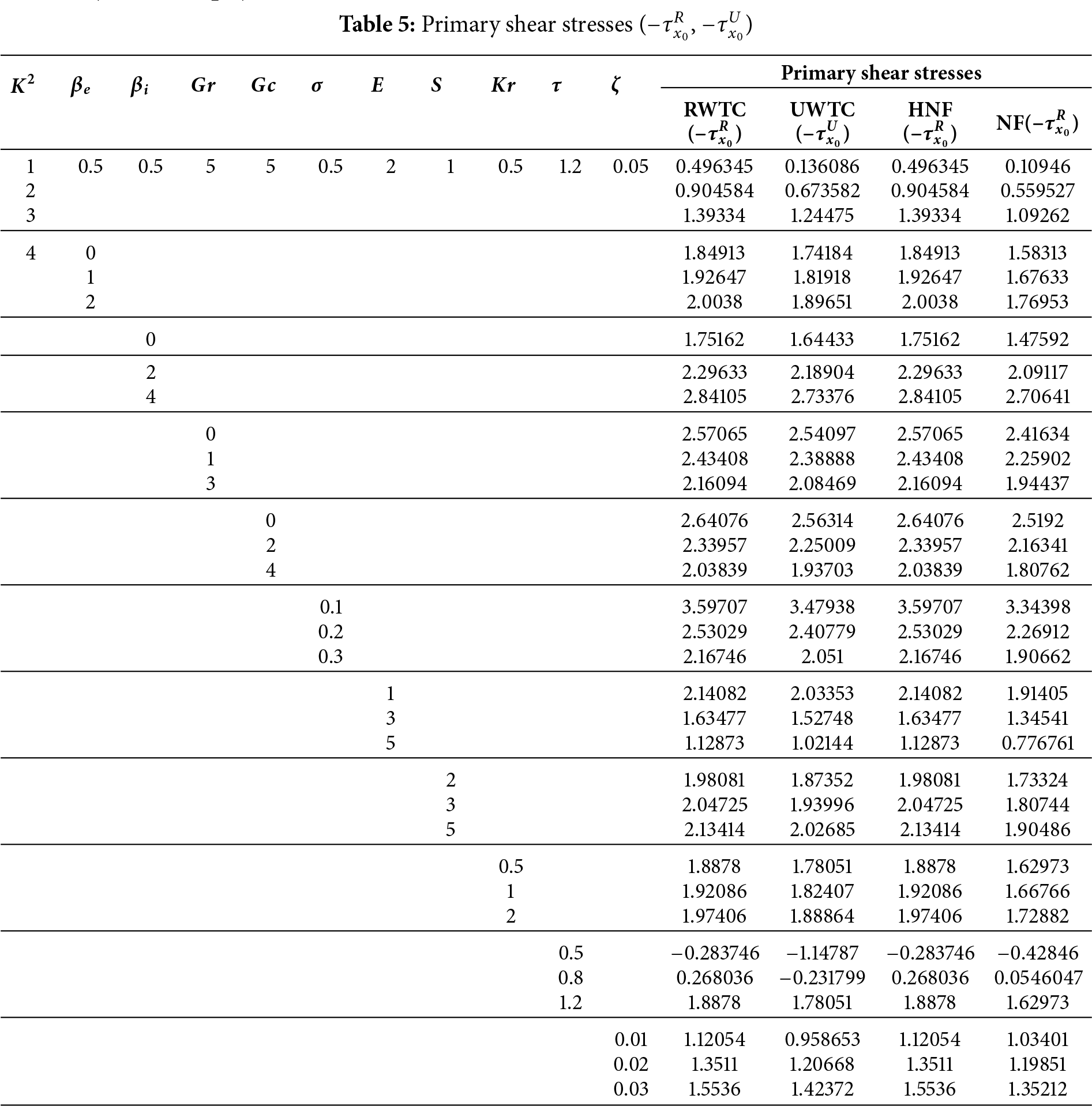
The rotation parameter
In contrast, buoyancy-related parameters show the opposite tendency. Higher thermal (
Electromagnetic effects exhibit contrasting influences. An increase in the modified Hartmann number
Other physical parameters further modulate the shear behavior. A stronger chemical reaction rate
Overall,
Table 6 reports the dependence of the secondary wall shear stresses,
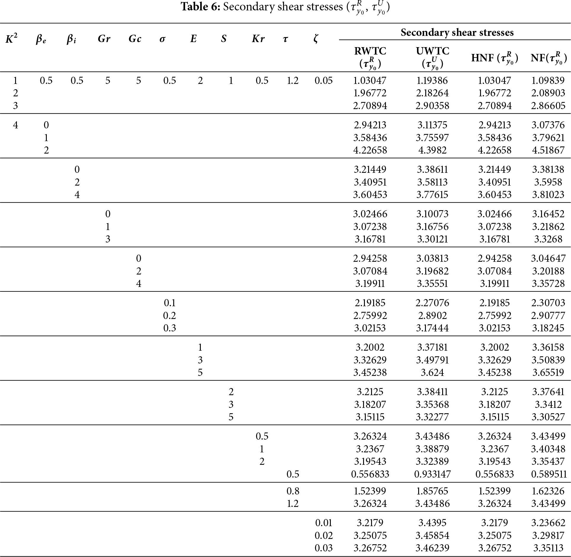
Unlike the primary stress, buoyancy through
The chemical reaction parameter
Comparisons between boundary conditions reveal that
The variations of the non-dimensional heat transfer rate (HTR) with respect to selected control parameters are summarized in Table 7. The analysis focuses on the effects of the radiation parameter (
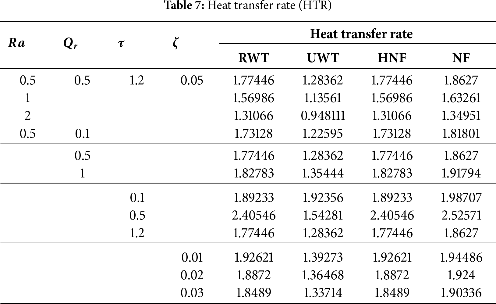
An increase in
Conversely, larger
The temporal behavior of HTR shows distinct characteristics under RWT and UWT. In the UWT case, the heat transfer rate steadily decreases with
The impact of nanoparticle concentration is somewhat counterintuitive. As
Table 8 outlines the sensitivity of the non-dimensional mass transfer rate (MTR) to the chemical reaction rate constant (
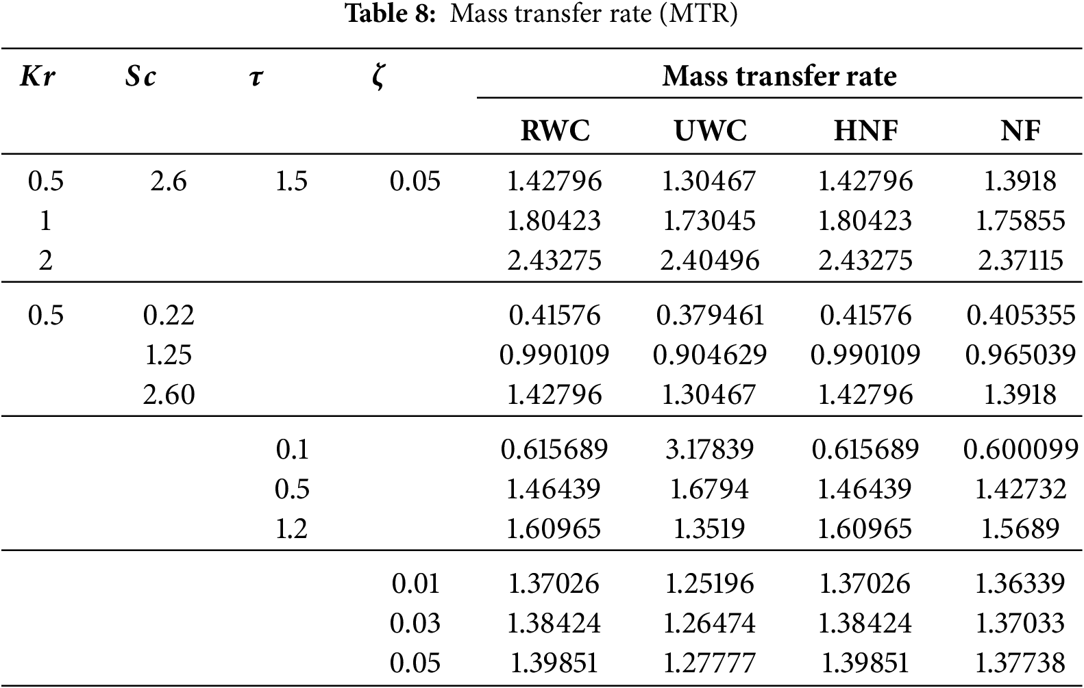
Increasing
The Schmidt number also plays a critical role: higher
Temporal evolution again depends on the imposed boundary. In UWC, the mass transfer rate declines with time, as the initially strong gradient at the wall relaxes when diffusion progresses toward equilibrium. Under RWC, however, the imposed time-dependent concentration increases the gradient continuously, causing MTR to rise with
Finally, the effect of nanoparticle loading shows a positive contribution: larger
Overall, RWC conditions consistently generate stronger mass transfer than UWC, and hybrid suspensions provide marginally improved performance compared to conventional nanofluids. These findings underline how both reactive kinetics and nanoparticle synergy can be harnessed to control solutal transport in advanced nanofluid systems.
4.9 Artificial Neural Network (ANN) Framework
Artificial Neural Networks (ANNs) offer a flexible data-driven strategy for approximating highly nonlinear input-output relations that are often difficult to capture using classical analytical or regression techniques. Inspired by the connectivity of biological neurons, ANNs can map multiple interacting parameters to physical outcomes with remarkable precision. In the present analysis, the ANN serves as a surrogate model for predicting transport quantities obtained from a hybrid nanofluid system.
The learning process is carried out using the Levenberg-Marquardt backpropagation (LMBP) scheme. This hybrid optimization technique effectively merges the fast convergence properties of Newton-like algorithms with the stability of gradient descent. As a result, the method ensures rapid adjustment of synaptic weights even in scenarios where the error surface is highly nonlinear. Such efficiency is especially advantageous in fluid mechanics applications, where the governing equations involve several coupled nonlinearities associated with buoyancy forces, electromagnetic stresses, and nanoparticle interactions.
The ANN structure used in this study consists of three key components (See Fig. 11):
• An input layer encoding dimensionless control parameters such as the thermal Grashof number (
• A hidden layer activated by a nonlinear transfer function. Here, the Tan-Sigmoid function is selected since it compresses large variations of input into a bounded interval, thereby enabling the network to approximate threshold-like phenomena.
• An output layer with a linear activation rule, producing continuous predictions of wall shear stress, heat transfer, or solute flux.
The governing activation laws are:
where
To prevent overfitting and ensure robustness, the dataset is partitioned into training, validation, and testing subsets. Training focuses on minimizing the mean squared deviation between ANN predictions and reference data. Validation continuously checks the model,s ability to generalize, while testing evaluates performance on unseen cases, thereby ensuring predictive reliability.
The ANN predictive performance is quantified through the following indicators:
Figs. 12–15 illustrate the regression outcomes of the artificial neural network (ANN) in predicting transport quantities such as the primary and secondary shear stresses, the wall heat flux (HTR), and the solutal transfer rate (MTR) for both conventional
For the primary shear stress (Fig. 12), the ANN achieves near-ideal regression under RWTC settings, with
The secondary shear stress predictions (Fig. 13) also demonstrate
Heat transfer rate predictions (Fig. 14) show similarly robust regression behavior. Under dynamic heating (RWT), the ANN yields
Mass transfer regression plots (Fig. 15) reveal
4.9.2 Mean Squared Error (MSE)
Figs. 16–19 illustrate the evolution of the mean squared error (MSE) during the training, validation, and testing phases of the artificial neural network (ANN) employed to forecast fundamental transport quantities, namely the primary and secondary shear stresses (SS), the wall heat transfer rate (HTR), and the solutal mass transfer rate (MTR). Each case corresponds to distinct boundary conditions and fluid formulations, thereby reflecting the ability of the ANN to generalize across varying thermo-fluidic environments.
In Fig. 16, the ANN performance in predicting the primary shear stress is assessed. Under ramp-type wall heating and concentration (RWTC) conditions (Fig. 16a), the network converges with a minimum MSE of
Fig. 17 demonstrates the ANN accuracy for secondary shear stress. The RWTC setting (Fig. 17a) shows excellent convergence with
The predictive capacity for wall heat transfer is shown in Fig. 18. Under ramped heating (RWT) (Fig. 18a), the MSE stabilizes at
Mass transfer rate learning is depicted in Fig. 19. The RWC setting (Fig. 19a) yields an error of
The progression of the ANN training process can be evaluated through the monitoring of internal parameters such as the gradient magnitude, the adaptive learning coefficient (
For primary SS (Fig. 20), convergence is characterized by small final gradients, indicating that the optimization algorithm effectively reduced the residual error. In the RWTC scenario (Fig. 20a), convergence is achieved at epoch 106 with both a very low gradient (
The evolution for secondary SS is depicted in Fig. 21. RWTC conditions (Fig. 21a) yield smooth convergence with a gradient of
Training curves for HTR predictions (Fig. 22) emphasize sensitivity to thermal boundary conditions. For RWTC (Fig. 22a), the model stabilizes at epoch 57 with
For MTR predictions (Fig. 23), RWTC conditions (Fig. 23a) reach convergence efficiently at epoch 41, with a very small gradient (
Figs. 24–27 display the error histograms, each divided into 20 bins, corresponding to the ANN-based predictions of the primary shear stress (SS), secondary shear stress (SS), heat transfer rate (HTR), and mass transfer rate (MTR). These graphical results provide a statistical perspective on the deviation between network estimations and the exact target values, thereby clarifying both the bias and the generalization efficiency of the predictive model.
In Fig. 24, the histogram of the primary SS highlights the level and direction of predictive bias. Under the RWTC case (Fig. 24a), the distribution is nearly symmetric around zero, with a negligible negative displacement (
The secondary SS error distributions are presented in Fig. 25. For the RWTC case (Fig. 25a), the histogram is slightly skewed toward positive values (
The prediction error for HTR is illustrated in Fig. 26. Under RWTC (Fig. 26a), the histogram is centered slightly above zero with a bias of
Finally, Fig. 27 reports the error characteristics for MTR. In RWTC (Fig. 27a), the zero error remains practically insignificant (
4.10 ANFIS Architecture and Training Performance
The Adaptive Neuro-Fuzzy Inference System (ANFIS) integrates neural network learning capabilities with fuzzy logic inference rules, making it a powerful tool for modeling complex, nonlinear systems such as hybrid nanofluid heat transfer. In the present study, ANFIS is trained using five key input parameters: thermal radiation (
The system operates in multiple layers: the input layer receives crisp values of physical variables; the input membership function (inputmf) layer transforms these inputs into fuzzy sets using predefined membership functions. The rule layer then evaluates all possible combinations of fuzzy rules, capturing interactions between input parameters through logical conjunctions (AND operations). The output membership function (outputmf) layer aggregates the rule-based outputs, and the final layer produces a single crisp output representing the estimated HTR.
During training, ANFIS employs a hybrid learning algorithm that combines least squares estimation and backpropagation to optimize both the membership function parameters and the rule consequences. The model converged rapidly with a minimal root mean square error (RMSE) of
4.11 ANFIS-Based Prediction of Heat Transfer Rate (HTR)
Fig. 29 provides a detailed investigation of the heat transfer rate (HTR) using the Adaptive Neuro-Fuzzy Inference System (ANFIS), highlighting the interplay of thermal radiation (
Fig. 29a,b presents the combined influence of thermal radiation (
The variation of HTR with time (
Fig. 29e,f depicts the combined effects of nanoparticle volume fraction (
The joint effect of heat source intensity (
Fig. 29i,j investigates the coupled roles of time (
Overall, the ANFIS-based analysis effectively captures the nonlinear and coupled behavior of heat transfer in hybrid nanofluid systems subjected to radiative, internal, particulate, and transient influences. The interplay among
This study presents a comprehensive neuro-fuzzy computational analysis of the transport behavior in a highly electrically conducting copper-titanium dioxide-water hybrid nanofluid flowing through a squarely elevated Riga tunnel. The analysis accounts for Hall and ion-slip current effects, electromagnetic radiation, first-order chemical reactions, and combined thermal and solutal gradients, all under the influence of a strong rotational electromagnetic field. The governing partial differential equations are solved using the Laplace Transform (LT) technique, yielding closed-form solutions for key physical quantities. Compact analytical expressions are derived to elucidate the fluid’s response to various physical influences. A graphical and tabular investigation is carried out for different cases involving (RWTC, and UWTC), and (HNF, NF) configurations. To further enhance the predictive capability of the model, a dataset generated using Mathematica was employed to train, validate, and test an Artificial Neural Network (ANN) model using the Levenberg-Marquardt backpropagation algorithm (ANN-LMBPA) with a 70%–15%–15% data split. This ANN framework was utilized to evaluate model performance metrics, state evolution parameters, error histograms, and regression diagnostics. Furthermore, the Adaptive Neuro-Fuzzy Inference System (ANFIS) was deployed to model the heat transfer rate (HTR), capturing complex nonlinear interdependencies between parameters. ANFIS-based 3D surface and pseudo-color plots were constructed to visualize the influence of paired parameters on HTR. The major findings of this investigation are summarized below:
• Increasing the rotation parameter suppresses primary velocity while enhancing secondary velocity under both RWTC and UWTC conditions.
• A higher modified Hartmann number enhances both velocity components due to intensified Lorentz forces.
• Hall and ion-slip currents reduce primary velocity but promote secondary flow in all boundary and fluid cases.
• Expanding magnet and electrode width leads to a noticeable decline in both velocity components.
• With the progression of time, both temperature and concentration profiles exhibit an increasing trend for HNF and NF.
• Species concentration decreases with higher Schmidt numbers and chemical reaction rates under RWC and UWC.
• Primary and secondary shear stresses increase significantly with the rotation parameter at the Riga wall for RWTC and UWTC conditions.
• Primary shear stress is greater in HNF than NF, while secondary shear stress shows the opposite trend.
• HTR decreases with rising radiation intensity across all thermal boundary conditions.
• HNF exhibits consistently lower HTR than NF.
• Increasing chemical reaction rate boosts MTR across all boundary and fluid cases.
• The ANN-LMBPA model achieved high accuracy with MSE in the range
• The ANFIS model yielded a low RMSE of 0.011012 for HTR prediction, demonstrating high accuracy and efficient convergence.
It is worth mentioning that the present analysis is confined to laminar, two-dimensional, single-phase hybrid nanofluid flow with constant thermophysical properties and idealized ramped boundary conditions within a squarely elevated Riga tunnel. The possible influences of nanoparticle agglomeration, turbulent mixing, temperature-dependent viscosity and conductivity, and spatially varying electromagnetic fields were not incorporated in this framework. Future investigations may address these aspects and complement the current theoretical findings with experimental or numerical validations to further enhance the model’s applicability to realistic engineering systems.
Acknowledgement: None.
Funding Statement: The authors received no funding for the publication of this article.
Author Contributions: Asgar Ali: Conceptualization, Methodology, Investigation, Formal analysis, Writing—original draft. Nayan Sardar: Software, Visualization, Validation, Writing—original draft. Poly Karmakar: Data curation, Visualization, Investigation, Methodology, Writing—original draft. Sanatan Das: Conceptualization, Methodology, Investigation, Supervision, Writing—review & editing. All authors reviewed the results and approved the final version of the manuscript.
Availability of Data and Materials: Data will be available on request.
Ethics Approval: Not applicable.
Conflicts of Interest: The authors declare no conflicts of interest to report regarding the present study.
Nomenclature
| Symbols | Description |
| Concentration (mol | |
| Specific heat at constant pressure (J kg−1K−1) | |
| Left Riga plate concentration (mol | |
| Right Riga plate concentration (mol | |
| Mass diffusivity ( | |
| Modified Hartmann number | |
| Acceleration due to gravity (m | |
| Solutal Grashof number | |
| Thermal Grashof number | |
| Heaviside unit step function | |
| Complex unity ( | |
| Characteristic electric strength by electrodes (M | |
| Thermal conductivity (W | |
| Medium’s absorption coefficient | |
| Rotation parameter | |
| Permeability of porous medium ( | |
| Chemical reaction parameter | |
| Chemical reaction coefficient (M | |
| Width of electrodes (m) | |
| Characteristic magnetic strength by magnets (T) | |
| Prandtl number | |
| Radiative heat flux (kg | |
| Heat absorption coefficient | |
| Heat absorption parameter | |
| Radiation parameter | |
| Dimensionless width of magnets and electrodes | |
| Schmidt number | |
| Time (s) | |
| Characteristic time (s) | |
| Temperature (K) | |
| Left Riga plate temperature (K) | |
| Right Riga plate temperature (K) | |
| Velocity (m | |
| Reference velocity (m | |
| Dimensionless velocity | |
| Cartesian coordinates (m) | |
| Greek Symbols | |
| Hall parameter | |
| Ion-slip parameter | |
| Volumetric solutal expansion coefficient ( | |
| Volumetric thermal expansion coefficient ( | |
| Nanoparticle volume fraction (NVF) | |
| Dimensionless variable | |
| Dimensionless temperature | |
| Dynamic viscosity (kg | |
| Kinematic viscosity ( | |
| Laplace transform parameter | |
| Density (kg | |
| Stephen-Boltzmann constant (J | |
| Permeability parameter | |
| Dimensionless time | |
| Dimensionless concentration | |
| Volume fraction of Cu NPs | |
| Volume fraction of | |
| Angular velocity ( | |
| Subscripts | |
| Cu nanoparticles | |
| Base fluid | |
| Nanofluid | |
| Hybrid nanofluid | |
| Abbreviation | |
| AI | Artificial intelligence |
| ANFIS | Adaptive Neuro-Fuzzy Inference System |
| ANN | Artificial neural network |
| HNF | Hybrid nanofluid |
| HTR | Heat transfer rate |
| LMBPA | Levenberg-Marquardt backpropagation algorithm |
| LT | Laplace transform |
| MHD | Magnetohydrodynamics |
| MTR | Mass transfer rate |
| NF | Nanofluid |
| NPs | Nanoparticles |
| PSS | Primary shear stress |
| RWC | Ramped wall concentration |
| RWT | Ramped wall temperature |
| RWTC | Ramped wall temperature and concentration |
| SSS | Secondary shear stress |
| UWC | Uniform wall concentration |
| UWT | Uniform wall temperature |
| UWTC | Uniform wall temperature and concentration |
References
1. Choi S. Enhancing thermal conductivity of fluid with nanoparticles. In: Developments and applications of non-newtonian flows. New York, NY, USA: ASME; 1995. p. 99–105. doi:10.1115/imece1995-0926. [Google Scholar] [CrossRef]
2. Buongiorno J. Convective transport in nanofluids. J Heat Transf. 2006;128(3):240–50. doi:10.1115/1.2150834. [Google Scholar] [CrossRef]
3. Boujelbene M, Rehman S, Jazaa Y, Hashim, Dhaou MH. Thermodynamics of hydromagnetic boundary layer flow of prandtl nanofluid past a heated stretching cylindrical surface with interface slip. J Taiwan Inst Chem Eng. 2024;155:105310. doi:10.1016/j.jtice.2023.105310. [Google Scholar] [CrossRef]
4. Asiri F, Rehman S, Drissi N. Sensitivity analysis of cattaneo-christov heat and mass flux model effects in stefan blowing flow of ferromagnetic nanofluid: numerical simulations. Res Chem. 2025;16(1):102490. doi:10.1016/j.rechem.2025.102490. [Google Scholar] [CrossRef]
5. Khan Y, Akram S, Athar M, Saeed K, Razia A, Alameer A. Alameer, Mechanism of thermally radiative prandtl nanofluids and double-diffusive convection in tapered channel on peristaltic flow with viscous dissipation and induced magnetic field. Comput Model Eng Sci. 2023;138(2):1501–20. doi:10.32604/cmes.2023.029878. [Google Scholar] [CrossRef]
6. Uddin M, Rasel S. Magnetohydrodynamic nanofluid flow in a u-shaped enclosure under radiative heat flux and exothermic chemical reactions. Thermal Adv. 2025;3(2):100044. doi:10.1016/j.thradv.2025.100044. [Google Scholar] [CrossRef]
7. Uddin MJ, Kalbani KSAl, Rahman MM, Alam MS, Al-Salti N, Eltayeb I. Fundamentals of nanofluids: evolution, applications and new theory. Int J Biomathem Syst Biol. 2016;2(1):1–32. [Google Scholar]
8. Sarkar J, Ghosh P, Adil A. A review on hybrid nanofluids: recent research development and applications. Renew Sustain Energ Rev. 2015;43(5):164–77. doi:10.1016/j.rser.2014.11.023. [Google Scholar] [CrossRef]
9. Ghani SNA, Noor NFM. Radiative blood-based hybrid copper-graphene nanoliquid flows along a source-heated leaning cylinder. Comput Model Eng Sci. 2023;139(1):1017–37. doi:10.32604/cmes.2023.031372. [Google Scholar] [CrossRef]
10. Ahmad S, Ali K, Faridi AA, Ashraf M. Novel thermal aspects of hybrid nanoparticles cu-tio2 in the flow of ethylene glycol. Int Commun Heat Mass Transf. 2021;129(2):105708. doi:10.1016/j.icheatmasstransfer.2021.105708. [Google Scholar] [CrossRef]
11. Manigandan J, Iranian D, Alqahtani AM, Khan I, Bakouri M, Ashmaig MA. Effects of thermal radiation on tio2-cu/water hybrid nanofluid: a finite difference discretization. J Radiat Res Appl Sci. 2024;17(4):101173. doi:10.1016/j.jrras.2024.101173. [Google Scholar] [CrossRef]
12. Meena RR, Sharma P. Thermal and mass diffusion in chemically reactive, radiative hybrid nanofluid (cu and tio2) flow over a rotating disk. Int J Thermoflu. 2025;26:101104. doi:10.1016/j.ijft.2025.101104. [Google Scholar] [CrossRef]
13. Islam MS, Islam S, Siddiki MN-A-A. Numerical simulation with sensitivity analysis of mhd natural convection using cu-tio2-h2o hybrid nanofluids. Int J Thermoflu. 2023;20:100509. doi:10.1016/j.ijft.2023.100509. [Google Scholar] [CrossRef]
14. Pattnaik P, Shamshuddin M, Mishra S, Panda S. Exploring darcy dissipation modulation of nanofluid with titanium dioxide (tio2) and copper (cu) for enhanced thermal performance in a vertical sheet. Case Stud Therm Eng. 2025;68(1):105904. doi:10.1016/j.csite.2025.105904. [Google Scholar] [CrossRef]
15. Kataria HR, Patel HR. Effects of chemical reaction and heat generation/absorption on magnetohydrodynamic (mhd) casson fluid flow over an exponentially accelerated vertical plate embedded in porous medium with ramped wall temperature and ramped surface concentration. Propulsion Power Res. 2019;8(1):35–46. doi:10.1016/j.jppr.2018.12.001. [Google Scholar] [CrossRef]
16. Asogwa K, Bilal S, Animasaun I, Mebarek-Oudina F. Insight into the significance of ramped wall temperature and ramped surface concentration: the case of casson fluid flow on an inclined riga plate with heat absorption and chemical reaction. Nonlinear Eng. 2021;10(1):213–30. doi:10.1515/nleng-2021-0016. [Google Scholar] [CrossRef]
17. Nagaraju L, Naikoti K, Krishna MV. Chemical reaction and soret effects on mhd convective flow of second grade fluid through an absorbent medium with ramped wall temperature as well as ramped surface concentration. J Indian Chem Soc. 2023;100(1):100818. doi:10.1016/j.jics.2022.100818. [Google Scholar] [CrossRef]
18. Scheidegger AE. The physics of flow through porous media. Toronto, ON, Canada: University of Toronto Press; 1958. [Google Scholar]
19. Khalid A, Khan I, Khan S, Shafie S. Unsteady mhd free convection flow of casson fluid past over an oscillating vertical plate embedded in a porous medium. Eng Sci Technol Int J. 2015;18(3):309–17. doi:10.1016/j.jestch.2014.12.006. [Google Scholar] [CrossRef]
20. Kataria HR, Patel HR. Radiation and chemical reaction effects on mhd casson fluid flow past an oscillating vertical plate embedded in porous medium. Alex Eng J. 2016;55(1):583–95. doi:10.1016/j.aej.2016.01.019. [Google Scholar] [CrossRef]
21. Kataria HR, Patel HR. Soret and heat generation effects on mhd casson fluid flow past an oscillating vertical plate embedded through porous medium. Alex Eng J. 2016;55(1):2125–37. doi:10.1016/j.aej.2016.06.024. [Google Scholar] [CrossRef]
22. Kumar NN, Ojjela O, Sastry DRVSRK. Effects of double stratification on mhd chemically reacting second-grade fluid through porous medium between two parallel plates. Heat Transfer. 2019;48(8):3708–23. doi:10.1002/htj.21564. [Google Scholar] [CrossRef]
23. Narahari M, Tippa S, Pendyala R, Fetecau C. Soret, heat generation, radiation and porous effects on mhd free convection flow past an infinite plate with oscillating temperature. J Therm Anal Calorim. 2021;143(3):2525–43. doi:10.1007/s10973-020-10229-5. [Google Scholar] [CrossRef]
24. Gulle N, Kodi R. Soret radiation and chemical reaction effect on mhd jeffrey fluid flow past an inclined vertical plate embedded in porous medium. Mat Today Proc. 2022;50(Pt 5):2218–26. doi:10.1016/j.matpr.2021.09.480. [Google Scholar] [CrossRef]
25. Rosseland S. Theoretical astrophysics. New York, NY, USA: Oxford University; 1936. [Google Scholar]
26. Cess RD. The interaction of thermal radiation with free convection heat transfer. Int J Heat Mass Transf. 1966;9(11):1269–77. doi:10.1016/0017-9310(66)90119-0. [Google Scholar] [CrossRef]
27. Narahari M. Transient free convection flow between long vertical parallel plates with ramped wall temperature at one boundary in the presence of thermal radiation and constant mass diffusion. Meccanica. 2012;47(8):1961–76. doi:10.1007/s11012-012-9567-9. [Google Scholar] [CrossRef]
28. Prakash D, Muthtamilselvan M. Effect of radiation on transient MHD flow of micropolar fluid between porous vertical channel with boundary conditions of the third kind. Ain Shams Eng J. 2014;5(4):1277–86. doi:10.1016/j.asej.2014.05.004. [Google Scholar] [CrossRef]
29. Sheikholeslami M, Ganji DD, Younus JM, Ellahi R. Effect of thermal radiation on magnetohydrodynamics nanofluid flow and heat transfer by means of two phase model. J Magn Magn Mater. 2015;374(1):36–43. doi:10.1016/j.jmmm.2014.08.021. [Google Scholar] [CrossRef]
30. Thriveni K, Mahanthesh B. Sensitivity analysis of nonlinear radiated heat transport of hybrid nanoliquid in an annulus subjected to the nonlinear boussinesq approximation. J Therm Anal Calorim. 2021;143(3):2729–48. doi:10.1007/s10973-020-09596-w. [Google Scholar] [CrossRef]
31. Ali A, Das S, Jana RN. Oblique rotational dynamics of chemically reacting tri-hybridized nanofluids over a suddenly moved plate subject to hall and ion slip currents, newtonian heating and mass fluxes. J Indian Chem Soc. 2023;100(4):100983. doi:10.1016/j.jics.2023.100983. [Google Scholar] [CrossRef]
32. Famakinwa O, Koriko O, Adegbie K. Analysis of chemically reactive squeezing flow of silica and titania hybrid nanoparticles in water-based medium between two parallel plates with higher order slip. Forc Mech. 2023;12(1228):100220. doi:10.1016/j.finmec.2023.100220. [Google Scholar] [CrossRef]
33. Xia W-F, Ijaz Khan M, Qayyum S, Imran Khan M, Farooq S. Aspects of constructive/destructive chemical reaction with activation energy for darcy-forchheimer hybrid nanofluid flow due to semi-infinite asymmetric channel with absorption and generation features. Ain Shams Eng J. 2021;12(3):2981–89. doi:10.1016/j.asej.2021.02.026. [Google Scholar] [CrossRef]
34. Khan MI, Alzahrani F. Binary chemical reaction with activation energy in dissipative flow of non-newtonian nanomaterial. J Theor Comput Chem. 2020;19(03):2040006. doi:10.1142/s0219633620400064. [Google Scholar] [CrossRef]
35. Manigandan J, Iranian D, Khan I, Mohammed NA, Alhazmi H. Numerical simulations of thermal heat conservation in hybrid nanofluids with chemical reaction, viscous dissipation, and inclination. Case Stud Therm Eng. 2024;58(14):104386. doi:10.1016/j.csite.2024.104386. [Google Scholar] [CrossRef]
36. Chauhan DS, Rastogi P. Radiation effects on natural convection MHD flow in a rotating vertical porous channel partially filled with a porous medium. Appl Math Sci. 2010;4(13):643–55. doi:10.1080/00986440903359061. [Google Scholar] [CrossRef]
37. Seth GS, Singh JK, Mahto N, Joshi N. Oscillatory hartmann flow in rotating channel with magnetized walls. Math Sci Lett. 2016;5(3):259–69. doi:10.18576/msl/050307. [Google Scholar] [CrossRef]
38. VeeraKrishna M, Reddy GS. Unsteady mhd reactive flow of second-grade fluid through porous medium in a rotating parallel plate channel. J Therm Analy. 2019;27(13):103–20. doi:10.1007/s41478-018-0108-3. [Google Scholar] [CrossRef]
39. Hayat T, Nadeem S, Khan AU. Numerical analysis of ag-cuo/water rotating hybrid nanofluid with heat generation and absorption. Can J Phys. 2019;97(6):644–50. doi:10.1139/cjp-2018-0011. [Google Scholar] [CrossRef]
40. Ahammad NA, VeeraKrishna M. Numerical investigation of chemical reaction, soret and dufour impacts on MHD free convective gyrating flow through a vertical porous channel. Case Stud Therm Eng. 2021;28(3):101571. doi:10.1016/j.csite.2021.101571. [Google Scholar] [CrossRef]
41. Sharma BK, Sharma P, Mishra NK, Fernandez-Gamiz U. Darcy-forchheimer hybrid nanofluid flow over the rotating riga disk in the presence of chemical reaction: artificial neural network approach. Alex Eng J. 2023;76(1):101–30. doi:10.1016/j.aej.2023.06.014. [Google Scholar] [CrossRef]
42. Jana RN, Kanch AK. Hall effect on unsteady couette flow under boundary layer approximations. J Phys Sci. 2001;7:74–86. [Google Scholar]
43. Ghosh SK. Effects of hall current on mhd couette flow in a rotating system with arbitrary magnetic field. Czech J Phys. 2002;52(1):51–63. doi:10.1023/a:1013913730086. [Google Scholar] [CrossRef]
44. Jha BK, Apere CA. Combined effects of hall current and ion-slip current on unsteady MHD couette flow in a rotating system. J Phys Soc Jpn. 2010;79(10):104401. doi:10.1143/jpsj.79.104401. [Google Scholar] [CrossRef]
45. Das S, Karmakar P, Sarkar S, Ali A, Jana RN, Kumar RSV. Flow dynamics in a revolving riga duct containing low-ionization fluid subject to hall and ion-slip electromotive forces. ZAMM-J Appl Math Mech/Zeitschrift Für Angewandte Mathematik Und Mechanik. 2025;105(5):e70056. doi:10.1002/zamm.70056. [Google Scholar] [CrossRef]
46. Gailitis A, Lielausis O. On a possibility to reduce the hydrodynamic resistance of a plate in an electrolyte. Appl Magnetohydrodyn. 1961;12:143–6. [Google Scholar]
47. Grinberg E. On determination of properties of some potential fields. Appl Magnetohydrodyn Rep Phys Inst Riga. 1961;12:147–54. [Google Scholar]
48. Ahmad A, Asghar S, Afzal S. Flow of nanofluid past a riga plate. J Magn Magn Mater. 2016;402:44–8. doi:10.1016/j.jmmm.2015.11.043. [Google Scholar] [CrossRef]
49. Ahmad R, Mustafa M, Turkyilmazoglu M. Buoyancy effects on nanofluid flow past a convectively heated vertical riga-plate: a numerical study. Int J Heat Mass Transf. 2017;111:827–35. doi:10.1016/j.ijheatmasstransfer.2017.04.046. [Google Scholar] [CrossRef]
50. Ahmad A, Ahmed S, Abbasi F. Flow and heat transfer analysis of copper-water nanofluid with temperature-dependent viscosity past a riga plate. J Magn. 2017;22(2):181–7. doi:10.4283/jmag.2017.22.2.181. [Google Scholar] [CrossRef]
51. Rasool G, Zhang T, Shafiq A. Second-grade nanofluidic flow past a convectively heated vertical riga plate. Physica Scr. 2019;94(12):125212. doi:10.1088/1402-4896/ab3990. [Google Scholar] [CrossRef]
52. Loganathan P, Deepa K. Electromagnetic and radiative casson fluid flow over a permeable vertical riga-plate. J Theor Appl Mech. 2019;57(4):987–98. doi:10.15632/jtam-pl/112421. [Google Scholar] [CrossRef]
53. Khatun S, Mollah T, Akter S, Islam MM, Alam M. Emhd couette flow of bingham fluid through a porous parallel riga plates with thermal radiation. Model Meas Control B. 2019;88(2–4):106–13. doi:10.18280/mmc_b.882-409. [Google Scholar] [CrossRef]
54. Nasrin S, Mondal RN, Alam MM. Unsteady couette flow past between two horizontal riga plates with hall and ion slip effects. Math Stat. 2021;9(4):552–65. doi:10.21203/rs.3.rs-574292/v1. [Google Scholar] [CrossRef]
55. Nasrin S, Mondal RN, Alam MM. Couette fluid flow through parallel riga plate with electromagnetic field. Quantum J Eng Sci Technol. 2023;4(4):74–94. [Google Scholar]
56. Asogwa KK, Mebarek-Oudina FM, Animasaun IL. Comparative investigation of water-based al_2o_3 nanoparticles through water-based cuo nanoparticles over an exponentially accelerated radiative riga plate surface via heat transport. Arab J Sci Eng. 2022;47(3):8721–38. doi:10.1007/s13369-021-06355-3. [Google Scholar] [CrossRef]
57. Upreti H, Pandey AK, Joshi N, Makinde OD. Thermodynamics and heat transfer analysis of magnetized casson hybrid nanofluid flow via a riga plate with thermal radiation. J Comput Biophys Chem. 2023;22(3):321–34. doi:10.1142/s2737416523400070. [Google Scholar] [CrossRef]
58. Ali A, Das S. Applications of neuro-computing and fractional calculus to blood streaming conveying modified trihybrid nanoparticles with interfacial nanolayer aspect inside a diseased ciliated artery under electroosmotic and lorentz forces. Int Commun Heat Mass Transf. 2024;152:107313. doi:10.1016/j.icheatmasstransfer.2024.107313. [Google Scholar] [CrossRef]
59. Karmakar P, Das S, Das S, Das S. Neuro-computational simulation of blood flow loaded with gold and maghemite nanoparticles inside an electromagnetic microchannel under rapid and unexpected change in pressure gradient. Electromagn Biol Med. 2025;44(2):137–72. doi:10.1080/15368378.2025.2453923. [Google Scholar] [PubMed] [CrossRef]
60. Karmakar P, Das S. Ai-powered computational analysis of dynamic responses in a vibrating riga sensor within a reactive platinum-cerium oxide-water mixture. Sens Actuators A-Phys. 2025;381(3):116028. doi:10.1016/j.sna.2024.116028. [Google Scholar] [CrossRef]
61. Maddina DK, Suresh Kumar Raju S, Gurram D, Nuwairan MAl. Dynamics of non-newtonian casson fluid and cattaneo-christov heat flux impacts on a rotating non-uniform surface due to coriolis force: a comparison study of anfis-pso and ann. Res Eng. 2024;23(1):102653. doi:10.1016/j.rineng.2024.102653. [Google Scholar] [CrossRef]
62. Dinesh kumar M, Díaz Palencia JL, Dharmaiah G, Wakif A, Noeiaghdam S, Fernandez-Gamiz U, et al. Anfis-pso analysis on axisymmetric tetra hybrid nanofluid flow of cu-cnt-graphene-tio2 with weg-blood under linear thermal radiation and inclined magnetic field: a bio-medicine application. Heliyon. 2025;11(1):e41429. doi:10.1016/j.heliyon.2024.e41429. [Google Scholar] [PubMed] [CrossRef]
63. Ali A, Mahrous YM, Elmannai H, Abduvalieva D, Karmakar P, Das S. Neuro-computational dynamics of an electromagnetically reactive copper-titania-water mixture within a quadratically accelerated riga channel with graduated thermo-solutal conditions. Int Commun Heat Mass Transf. 2025;169:109666. doi:10.1016/j.icheatmasstransfer.2025.109666. [Google Scholar] [CrossRef]
64. Attia HA. Ion slip effects on unsteady couette flow with heat transfer under exponential decaying pressure gradient. Tamkang J Eng. 2005;12(2):209–14. doi:10.1115/imece2005-80213. [Google Scholar] [CrossRef]
Cite This Article
 Copyright © 2025 The Author(s). Published by Tech Science Press.
This work is licensed under a Creative Commons Attribution 4.0 International License , which permits unrestricted use, distribution, and reproduction in any medium, provided the original work is properly cited.
 Downloads
 Citation Tools