
 Submit a Paper
 Propose a Special lssue
 Open Access
ARTICLE

A Subdomain-Based GPU Parallel Scheme for Accelerating Perdynamics Modeling with Reduced Graphics Memory
1 Hubei Key Laboratory of Theory and Application of Advanced Materials Mechanics, Wuhan University of Technology, Wuhan, 430070, China
2 Hubei Longzhong Laboratory, Wuhan University of Technology Xiangyang Demonstration Zone, Xiangyang, 441000, China
* Corresponding Authors: Jun Li. Email: ; Lisheng Liu. Email:
Computer Modeling in Engineering & Sciences 2026, 146(1), 7 https://doi.org/10.32604/cmes.2026.075980
Received 12 November 2025; Accepted 31 December 2025; Issue published 29 January 2026
 View Full Text
 Download PDF
Abstract
Peridynamics (PD) demonstrates unique advantages in addressing fracture problems, however, its nonlocality and meshfree discretization result in high computational and storage costs. Moreover, in its engineering applications, the computational scale of classical GPU parallel schemes is often limited by the finite graphics memory of GPU devices. In the present study, we develop an efficient particle information management strategy based on the cell-linked list method and on this basis propose a subdomain-based GPU parallel scheme, which exhibits outstanding acceleration performance in specific compute kernels while significantly reducing graphics memory usage. Compared to the classical parallel scheme, the cell-linked list method facilitates efficient management of particle information within subdomains, enabling the proposed parallel scheme to effectively reduce graphics memory usage by optimizing the size and number of subdomains while significantly improving the speed of neighbor search. As demonstrated in PD examples, the proposed parallel scheme enhances the neighbor search efficiency dramatically and achieves a significant speedup relative to serial programs. For instance, without considering the time of data transmission, the proposed scheme achieves a remarkable speedup of nearly 1076.8× in one test case, due to its excellent computational efficiency in the neighbor search. Additionally, for 2D and 3D PD models with tens of millions of particles, the graphics memory usage can be reduced up to 83.6% and 85.9%, respectively. Therefore, this subdomain-based GPU parallel scheme effectively avoids graphics memory shortages while significantly improving the computational efficiency, providing new insights into studying more complex large-scale problems.Keywords
Supplementary Material
Supplementary Material FileThe damage, fracture, and failure problems are commonly observed in aerospace, civil, mechanical, and other engineering fields. However, it is challenging to accurately simulate and analyze these complicated phenomena using numerical methods. Classical mesh-based methods, such as the finite difference method (FDM), finite volume method (FVM), and finite element method (FEM), have tried to address these issues [1–3].
However, these approaches based on classical continuum mechanics, are discretization approaches employed to discretize classical partial differential equation (PDEs), which are not applicable to fracture problems. To overcome these limitations, Silling et al. [4–6] proposed a nonlocal Peridynamics (PD) theory, which is also a continuum mechanics theory but one that can be discretized with meshfree point collocation or finite elements. In contrast to classical continuum mechanics approaches, PD reformulates classical partial differential equations into integrodifferential equations, which allow damage to originate in multiple locations within the material and propagate along arbitrary paths without the need for special crack propagation criteria. Therefore, PD provides a coherent theoretical framework for dealing with fracture problems. Until now, PD theory has been demonstrated broad applicability and significant engineering values in a variety of fields, including fracture analysis of brittle materials such as ceramics [7] and glass [8], interlaminar delamination predictions of composite materials [9], crack propagation assessment in concrete structures [10], and prediction of crack evolution during hydraulic fracturing of shale [11].
The meshfree point collocation method is one of the commonly used approaches for discretizing the governing equations of PD theory [12]. Similar to many meshfree methods, the neighbor search and neighbor list maintenance are rather expensive in PD, which are not necessary in classical mesh-based methods due to their mesh connectivity [13]. Therefore, PD requires higher computational and storage resources than classical mesh-based methods, posing significant challenges for solving large-scale problems [14].
To extend the application of PD theory, it is critical to improve their computational efficiency and reduce the memory usage [15,16]. One effective approach is to enhance the efficiency of the PD theory itself, such as using a uniform grid-based approach to optimize neighbor retrieval and link-list pairing [17]. Another strategy involves combining local theories with global theories to minimize computations in non-core regions [18]. Moreover, Mao et al. [19] proposed a mixed-precision GPU computation for Smoothed Particle Hydrodynamics (SPH) method, where low-precision was applied to accuracy-insensitive components to reduce computation time. And, Xu et al. [20] explored machine learning scheme to reduce computational complexity, but their acceleration effect remains highly limited. Particularly, due to the independence of particle calculations, parallel computing is beneficial for the acceleration of meshfree discretization methods [21]. In 2012, the open-source project Peridigm was parallelized using CPU-based Message Passing Interface (MPI) and released as the first software package specifically developed for PD [22]. In addition, Fan and Li [23] attempted to accelerate PD computations using OpenMP. However, similar to the MPI-based approach, this CPU-parallel scheme still requires each processor to handle a large number of particles, limiting the effect of maximum parallelism. As a result, the improvement in acceleration efficiency is restricted to only an order of magnitude.
Recently, the development of GPUs offers a promising pathway for parallel implementation. Unlike CPUs, which provide 10 to 1000 independent active threads, GPUs can support over 100,000 active threads simultaneously [24]. Thus, GPU-based parallel programs have been developed for mesh-free discretization methods to achieve significantly higher efficiency. Boys et al. [25] proposed the PeriPy, a lightweight and high-performance Python package for solving PD problems on a CPU/GPU platform in solid mechanics. Its GPU solving efficiency is 3.7 to 7.3 times faster compared to existing OpenMP solvers. In addition, Crespo et al. [26] employed CUDA to accelerate DualSPHysics, generating an improvement of two orders of magnitude over its serial counterpart which provided a valuable reference for the parallelization of numerical simulation programs based on meshfree discretization methods. Moreover, Zheng et al. [14] developed a parallel PD program with finite element discretization for large deformation problems in thin-shell structures and achieved significant accelerations, further expanding the applicability of GPU parallel schemes in PD theory. Recently, Wang et al. [27] classified data types and designed a more efficient parallel scheme by optimizing graphics memory usage, resulting in an impressive 620.3× speedup. Noteworthy, although the GPU parallel schemes demonstrate significant efficiency improvements over serial programs, the computational size remains constrained by the limited memory capacity of GPUs. Bartlett and Storti [28] proposed a memory optimization method utilizing regular grids, reducing memory consumption by approximately 50%. Wang et al. [29] suggested a multi-GPU distributed parallel scheme, which exhibits great potential for large-scale simulations but requires additional hardware resources. Therefore, how to effectively use the limited graphics memory to perform larger-scale simulations remains a challenge.
Intriguingly, CUDA enables the packaging of GPU code into discrete functions (kernel functions) with data transferring between the host and device explicitly managed by the programmer [30,31]. This provides an opportunity to address the limitations of graphics memory on computational scale through optimizing data transfer strategies. Among various meshfree methods [32–34], the cell-linked list approach mainly divides the computational domain into small grid cells and then restricts neighbor searches to adjacent cells, which avoids the unnecessary traversal of unrelated particle pairs, thereby significantly improving the neighbor search efficiency. Moreover, the cell-linked list approach can also provide an efficient scheme for managing particle information within subdomains [35]. In the present study, we mainly employed the efficient particle management of the cell-linked list approach to partition the computational domain based on device capabilities and establish an effective data transfer strategy, enabling batch-wise computation on the GPU.
Consequently, in the present study, we proposed a GPU parallel scheme with subdomain computing. This scheme divided the computational model into multiple subdomains, recorded particles in each subdomain using a cell-linked list method, and then transferred particle information for only one subdomain at a time. By controlling the size and number of subdomains, this approach effectively avoids the constraints caused by limited graphics memory on computational scales. As implemented in PD models, the results demonstrate that the subdomain-based GPU parallel scheme exhibits outstanding acceleration performance while significantly reducing GPU memory usage. Particularly, unlike other methods that sacrifice computational accuracy to reduce memory consumption [28], this approach does not result in any loss of accuracy. Therefore, this study proposes an effective scheme for reducing graphics memory usage while maintaining acceleration performance in large-scale PD simulations. Noteworthy, as PD is discretized with the meshfree point collocation method, this scheme may provide significant insights into the acceleration of the meshfree method.
2 The Theory and Implementation of Subdomain-Based GPU Parallel Scheme
PD method exhibits significant advantages and excellent performance in crack simulation by introducing a non-local interaction range. Particularly, the bond-based PD (BB-PD) modeling exhibits better numerical stability compared to state-based PD. In addition, BB-PD models are easy to be implement, which can effectively demonstrate the computational efficiency of this parallel scheme. Therefore, in the present study, the subdomain-based GPU parallel scheme was introduced into two-dimensional (2D) and three-dimensional (3D) BB-PD calculations. The computational efficiency and graphics memory were then examined and compared with classical parallel schemes and serial programs without domain division. In the following, we will introduce the implementation of the subdomain-based GPU parallel scheme on BB-PD models.
2.1 Bond-Based Peridynamics Theory
In BB-PD theory, the model can be discretized into a number of material points. As shown in Fig. 1, a material point x located in a continuous domain has neighboring points in a domain Hx (horizon) with radius δ. ξ and η denote the relative positions and displacements of the material point x, respectively, and their expressions can be given as,
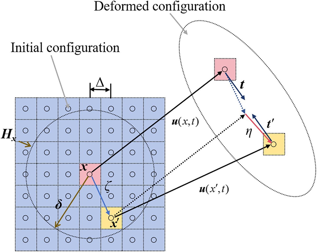
Figure 1: Schematic diagram of BB-PD theory
The force density vector arises from the bond connecting a pair of points in the deformed configuration. In BB-PD theory, the magnitudes of the force density are equal and parallel to the relative position vector ξ + η in the deformed configuration. Its expression is given as,
where, s represents the relative stretch of the bond and c represents the bond constant, which are defined by the following formula.
in which k1 and k2 are the 2D and 3D bulk modulus, respectively, and h is the thickness of the 2D model.
At any moment t, the motion equation of the material point x can be expressed as:
where, ρ(x) represents the mass density of material point x, and
The damage of the particle x is controlled by a damage function, as shown in Eqs. (7) and (8).
where, μ is a scalar function that depends on time t, with an initial value of 1. When the relative stretch s reaches the critical value s0, μ changes to 0, indicating that the bond between the two material points is completely fractured. In addition, for isotropic materials, since there is only one independent material constant c, BB-PD theory restricts the material’s Poisson’s ratio to specific values (1/3 for 2D problems and 1/4 for 3D problems).
2.2 Numerical Solution Procedure
A classical computational model for PD simulations, i.e., meshfree point collocation, was used here for the discretization. Therefore, the integrated formula in Eq. (6) can be expressed as,
To evaluate the efficiency of the proposed parallel scheme, we examined both quasi-static and transient 2D and 3D PD problems utilizing different integration methods. For transient problems, a central-difference explicit integration method (CDEI) was employed; while for quasi-static problems, an adaptive dynamic relaxation method (ADR) was used [37].
In CDEI, the relationship between the acceleration, velocity
where, the subscript n denotes the nth iteration.
In ADR, the PD equations of motion for all particles in the system can quickly converge to a steady state through introducing virtual inertia and damping terms. Then combined with CDEI, the displacement u and velocity
Here, D is the fictitious diagonal density matrix, whose diagonal elements can be selected based on Greschgorin’s theorem [12]. C is the damping coefficient, and F is the force vector composed of PD interactions and body forces.
2.3 The Cell-Linked List Method
The cell-linked list method is a spatial decomposition algorithm commonly used in meshfree methods [35]. Particularly, this method decomposes the whole model into a number of domains (cells) and records the particles within the cells in numbered order with the form of a linked list. In the present study, we employed this cell-linked list method to divide the computational domain, although the classical cell-linked list method has unique requirements on the size of the cell in optimizing neighbor search [32]. Therefore, each cell can be divided arbitrarily according to the user’s needs with the requirement that the size of the cell size should be larger than the particles’ interaction range. In addition, in order to fully employ the computational power of the GPU, each cell was kept at the same size as much as possible.
To record the particle number of each cell, as shown in Fig. 2, we created two arrays. Each element of the “head array” corresponds to a cell, records the largest particle number in the cell, and that element is used to address the “list array”, which records the next particle number in the cell. Following the index of the list, we then reached the last particle in the cell, i.e., the smallest particle, whose corresponding element was −1. This indicates that the index was terminated here. Consequently, the particles in each cell can be labeled according to the order of particle numbers from the largest to the smallest, which facilitates the extraction of the particle elements in the same cell in the original array and saving them in the order of the cell.
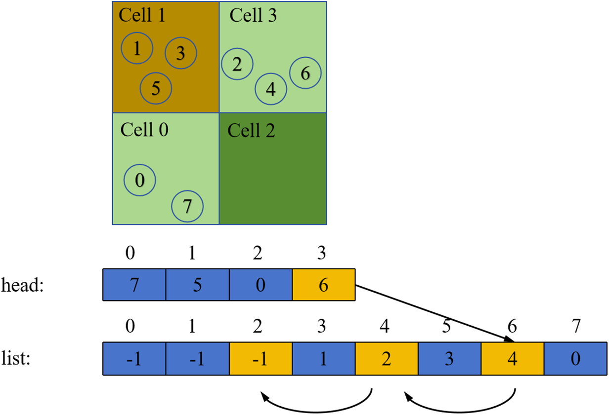
Figure 2: Method of cell-linked list
The main advantage of this proposed parallel scheme is its ability to effectively reduce the program’s GPU memory usage by dividing the computational domain, when the memory required for the simulation exceeds the hardware’s capacity. Therefore, it is more efficient to employ the size of each computational subdomain corresponding to the memory limit that the computer can provide. The size of the subdomain in the parallel scheme can be determined using the following method.
First, as shown in Fig. 3, the model was divided into several cells, and each cell was extended outward by a distance δ (the horizon) to form a boundary region. Cell A and boundary A constitute subdomain A. All cells are non-overlapping and fully cover the entire structure. The presence of the boundary regions ensures that the neighbor information of particles within each cell is complete, thereby guaranteeing computational accuracy. As shown in Eqs. (14) and (15), the number of subdomains (cell_Num) and the maximum number of particles in each subdomain (cell_maxNum) were closely related to the GPU configuration, especially the size of the GPU memory.
where,
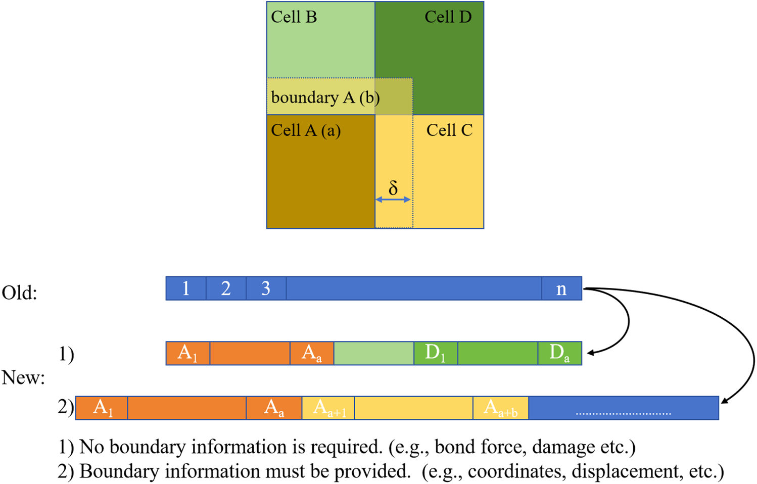
Figure 3: Domain partitioning based on cell-linked list
Based on the cell-linked list method described in Section 2.3, the particles within a subdomain were labeled in descending order of their original indices. Moreover, this study uses an explicit solution method to update particle motion, and the computation at the current time step only relies on the particle information from the previous time step. As shown in Fig. 3, before the computation at the current time step (time step k + 1), the particle information from the previous time step (time step k) is transferred to the new array (array “Old” to “New”) in the order of “Cell A, boundary A, Cell B, boundary B…”. The corresponding pseudo-code is outlined in Algorithms 1 and 2, as shown in Table 1. During computation, as shown in Fig. 4, the data are sequentially transferred to the device according to the subdomain order to perform calculations for the corresponding cells. Meanwhile, particle information of the boundary region remains read-only, thus consistently retaining data from the previous time step. Since only particles within the cells are updated, this effectively avoids redundant calculations on particles of the boundary region.
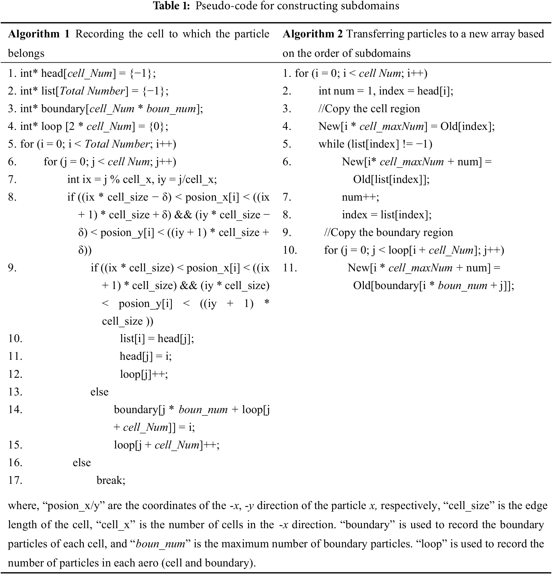
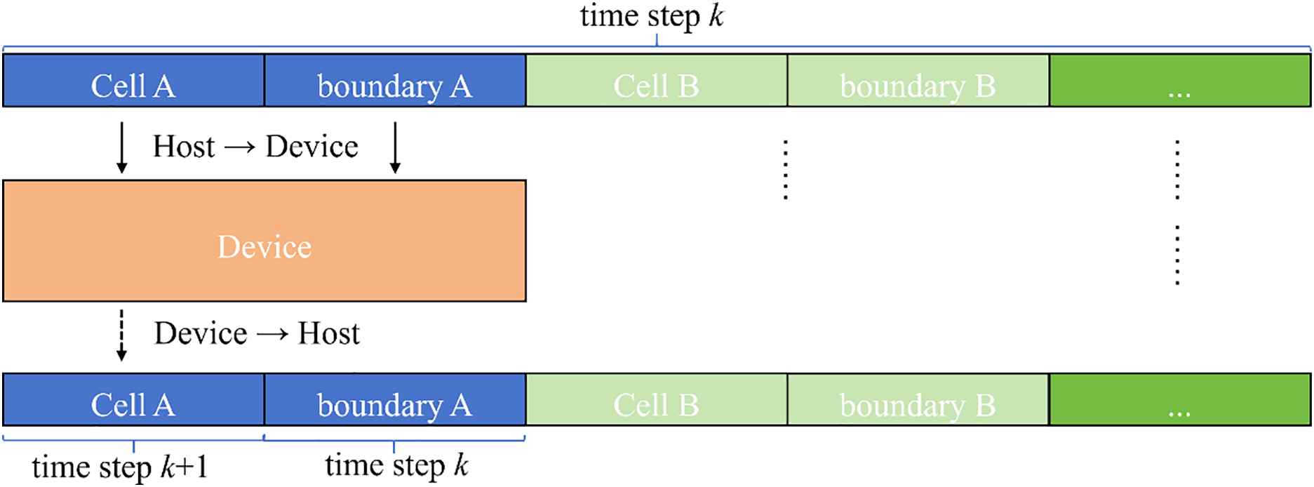
Figure 4: Schematic diagram of data transfer
After completing all computations for all subdomains, the method provided by Algorithm 2 (swap of the positions of arrays “New” and “Old”) may be employed to transfer the particle information corresponding to cells in array “New” to “Old”. This facilitates the output of results for the current time step. Meanwhile, the particle information stored in array “Old” has been updated. Therefore, combined the updated particle information in array “Old” with the boundary region particle copying procedure in Algorithm 2, the particle information in the boundary regions of array “New” can be updated. This process ensures that all particle information in array “New” is updated to the current time step, thereby maintaining consistency of particle data across subdomains.
In addition, based on data size and variable types, the data in the PD model can be divided into two categories: model parameters and particle-related data. Next, we will introduce how to manage these data. For model parameters, such as geometric and material parameters, they remain constant during the simulation and are accessed by all threads. When all threads in a warp read data from the same address, the broadcast mechanism and caching effects allow registers and constant memory to have faster access speeds than global memory, in which register access is particularly notable, although its capacity is the smallest. Therefore, few model parameters can be directly defined in registers. Otherwise, they can be stored in constant memory. However, constant memory variables cannot be changed by the kernel functions (device-side functions in GPU computing), thus these variables are required to be initialized on the host and then transferred to the device.
For particle-related data, such as spatial coordinates, displacements, velocities, and accelerations, these data occupy a significant amount of memory and are typically stored only in global memory. When the model is relatively large, global memory may not be able to store all particle information at once. In this case, we adopted the above method to rearrange the particle information on the host, and then stored it sequentially in a new array by subdomain. During calculations, these data were transmitted to the device in batches by subdomain, with each computation completed on the GPU for only one specific subdomain at a time.
Generally, one of the most commonly used GPU parallel schemes for PD simulations is particle mapping, which maps all calculations for each particle to the corresponding thread [25]. Due to the limited resources of Streaming Multiprocessors (SM), if too many thread blocks are launched, exceeding the resource capabilities of the SM, some thread blocks may not be able to execute immediately and must wait for previous blocks to be completed. This is a common “resource scheduling issue”, which often leads to underutilization of GPU resources and consequently affects the efficiency of parallel computations. Additionally, for extremely large datasets, a single grid may not be able to generate enough threads to handle all the data. To avoid the above issues, we established the relationship between particles and threads using a grid stride loop, as shown in Fig. 5. Here, threadIdx.x is the thread index within the thread block; blockIdx.x is the thread block index; blockDim.x is the number of threads in each dimension of the thread block; and gridDim.x is the number of thread blocks in each dimension of the grid.
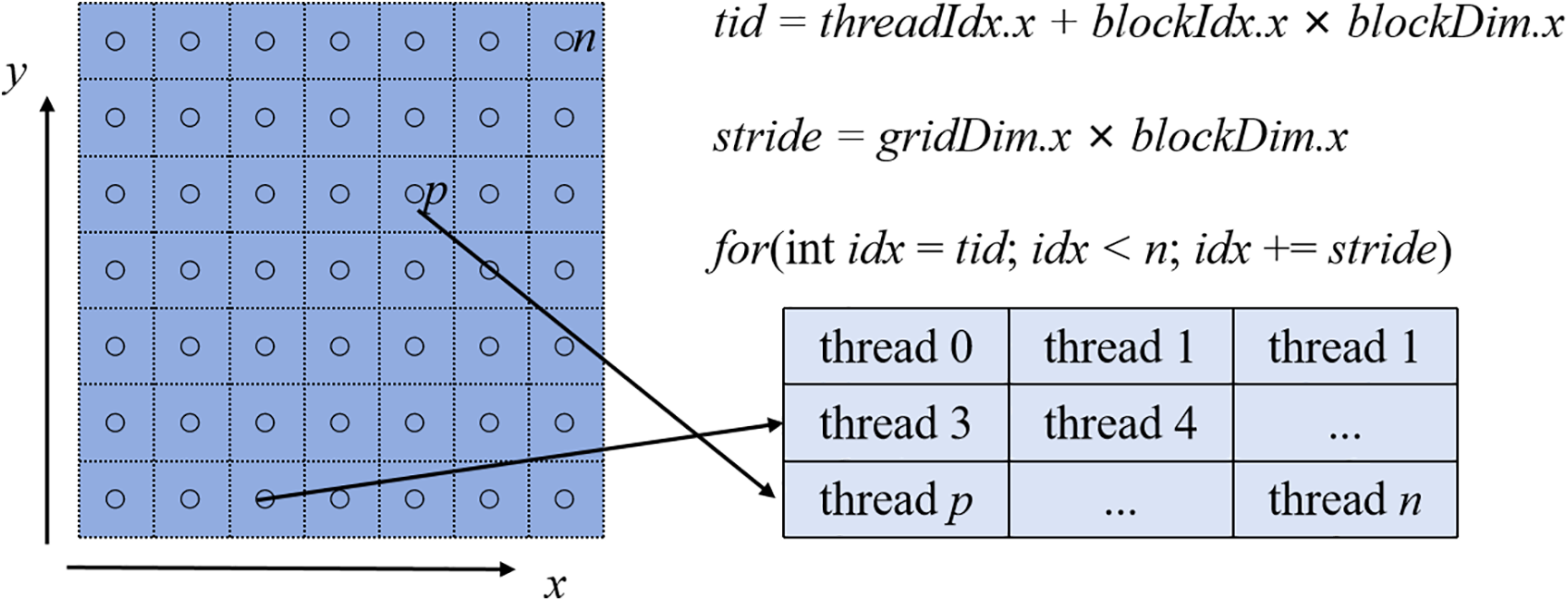
Figure 5: Schematic diagram of particle-mapping
In summary, the implementation of the subdomain-based GPU parallelism scheme for the BB-PD model is shown in Fig. 6. Noteworthy, in the present study, we mainly focus on linear elasticity and small deformation problems. Therefore, as shown in Fig. 6, the neighbor list was only constructed once at the beginning and not updated thereafter during the simulation [12]. However, this simplification is no longer appropriate for large deformation problems, where the neighbor list must be updated frequently to ensure the accuracy of the simulation.
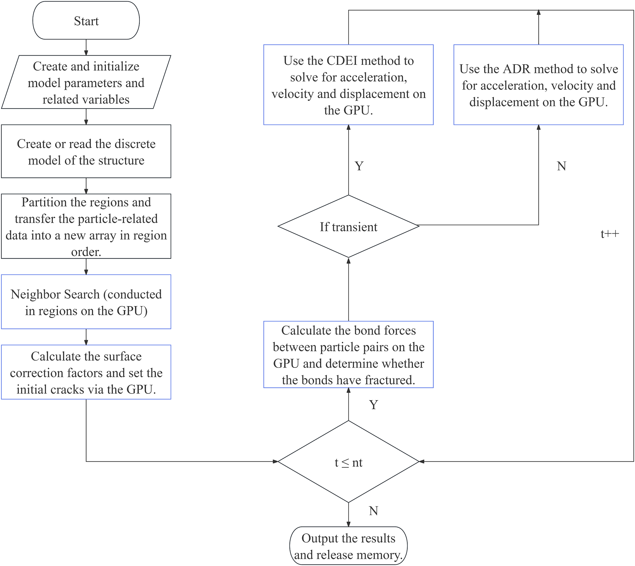
Figure 6: Implementation of subdomain-based GPU parallel scheme for BB-PD model
To further clarify the rationale behind the proposed subdomain-based GPU parallel scheme, this subsection provides a theoretical analysis of its core idea, i.e., the overall benefits introduced by subdomain decomposition.
During the neighbor search, each particle must be computed with all other particles to determine its neighbors, resulting in a spatial complexity of n(n − 1)/2. This approach is commonly known as the brute-force search method. To reduce the computational complexity of neighbor search, we employed the cell-linked list method in the present study. Here, when the model was evenly divided into m subdomains, each particle was only required to be calculated with the other particles within its own subdomain, leading to a spatial complexity of n(n − m)/2m. As a result, the domain division scheme can achieve a speedup of approximately m times for this step.
While the domain division does not reduce the complexity of the time integration. For example, in the bond force calculations, we only compute the bond forces between a particle and other k particles within its horizon, leading to a spatial complexity of kn. Therefore, the proposed subdomain-based parallel scheme is mainly for large-scale calculations.
On the one hand, in classical parallel schemes, the maximum computational scale is constrained by graphics memory capacity, whereas subdomain decomposition can overcome this limitation by reducing the number of particles within each computational domain, thereby enabling larger-scale simulations. On the other hand, computational efficiency in classical parallel schemes is limited by the maximum number of active threads. Large-scale tasks that exceed hardware limits must be queued for execution, which not only fails to enhance parallelism but also introduces additional scheduling and management overhead, thereby impeding performance gains. In contrast, in the subdomain-based GPU parallel scheme, adjusting the subdomain size can effectively reduce the workload per computation, allowing hardware resources to be fully utilized and thereby improving computational efficiency.
In this section, using BB-PD examples, we will first demonstrate the accuracy of the BB-PD simulations, and then examine the computational efficiency of the proposed GPU parallelization scheme by comparing it with the classical parallelization scheme and a serial program. In addition, two large-scale 2D and 3D PD models with tens of millions of particles will be used to demonstrate the applicability of this scheme for large-scale computations and its advantages in graphics memory usage.
The hardware environment used for these examples is listed as follows: CPU: Intel(R) Xeon(R) Gold 6248R @ 3.00 GHz; GPU: NVIDIA A100 80 GB. The serial program was written in C and run on the host side, while the parallel program was written in CUDA C (version 12.6). In the present study, the classical scheme represents the parallel scheme that employs the same programming logic, variable types, storage method, and mapping strategy as the subdomain-based GPU parallel scheme, but without subdomain partitioning. Therefore, the only difference between classical scheme and proposed subdomain-based GPU parallel scheme is whether the subdomain partitioning is performed. Additionally, readers may refer to the code provided in Table S1 of the Supplementary Materials to generate the neighbor list. Some relevant codes have been uploaded to the open source, Github, and the address is https://github.com/Yang-Z-K/A-subdomain-based-GPU-parallel-scheme-for-accelerating-Perdynamics-modeling.git.
As shown in Fig. 7, a rectangular plate was subjected to a uniform tensile loading of 200 MPa without any displacement constraints. The materials properties of this model are isotropic. The tensile loading was applied as a body force density on the surface layers (Rl) with a thickness of Δ (particle spacing) at the left and right edges of the structure. Table 2 lists the main model parameters. The particle spacing Δ was set to be 5 mm, resulting in a total of 20,000 particles. The horizon radius δ was chosen as 3.015Δ [5]. The time step Δt is 1.0 s, and the total number of time steps is 4000.
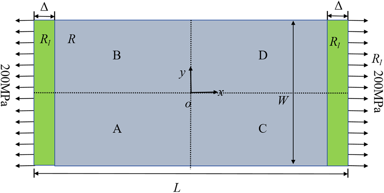
Figure 7: Geometry of a 2D plate
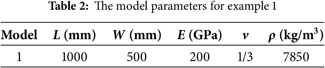
To verify the accuracy of the proposed parallel scheme, the above model was divided into four subdomains, as shown in Fig. 7. The steady-state solutions of ux(x, y = 0) and uy(x = 0, y) were compared with the analytical solutions, as shown in Fig. 8.
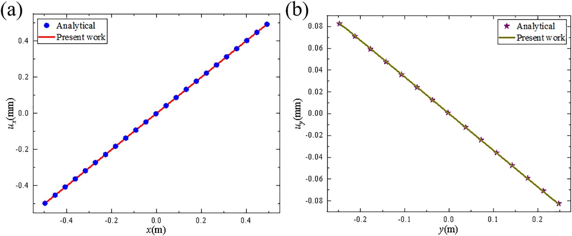
Figure 8: Displacement variations along the center lines, (a) ux (x, y = 0), (b) uy (x = 0, y)
The results suggest good agreement with the analytical solutions, demonstrating the accuracy of the BB-PD modeling.
In order to evaluate the effect of the kernel function configuration on computational efficiency, we further increased the number of particles of the model from 20,000 to 2 million. Fig. 9 shows the computation time for different number of threads (number of thread blocks × number of threads) without considering data transfer, when the number of particles reaches 2 million (cells = 4). It suggests that the required calculation time gradually decreases as the number of threads that can be called by the device increases. When the number of threads is slightly higher than the number of particles in the cell, reaching 512 × 1024, the running time is the lowest. As the total number of threads continues to increase, the running time of the program increases, due to the additional usage of thread scheduling and the limitation of memory bandwidth. Therefore, in all following calculations, the adopted kernel function configuration was always set to be slightly higher than the number of particles. Moreover, in large-scale simulations, the number of computed particles generally exceeds the number of active threads supported by the device. Therefore, in the following examples, we adopted the kernel configuration from the subdomain-based GPU parallel scheme as the baseline and kept the kernel configuration identical for both classical and subdomain-based GPU parallel schemes.
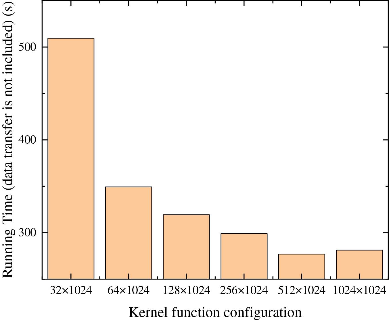
Figure 9: The variation of computation time with kernel function configuration
Next, the computational efficiency of proposed GPU parallel scheme was evaluated and compared with classical parallel schemes and serial programs. We defined the speedup of the parallel program, Sp, and used its variation with respect to the number of particles to evaluate the actual performance of the proposed GPU parallel scheme under a fixed hardware configuration.
in which TG and TC represent the time consumed by parallel computation and serial computation under the same conditions, respectively. Fig. 10a displays the time for the neighbor search by the all approaches. Obviously, the running time increases with the increase of the particles. Using the particle spacing Δ of 5, 2, 1, 0.67, and 0.5 mm, we constructed five PD models with various particles. Fig. 10b shows the speedup Sp of classical and subdomain-based parallel schemes as the particle numbers change. As the particle number increases from 20,000 to 2 million, the speedup ratio of the subdomain-based parallel scheme rises from 98.7× to 4193.0×, while the classical parallel scheme only increases from 101.1× to 1050.9×. It is evident that when the number of particles significantly exceeds the maximum number of active threads of the device, the advantage of the proposed parallel scheme in the neighbor search process becomes more pronounced. Specifically, when the particle number is over 1.125 million, this subdomain-based parallel scheme achieves a neighbor search runtime nearly 4× faster than the classical parallel scheme. This further validates the conclusion presented in Section 2.6.
Figure 10: (a) Running time for all scheme and (b) speedups as a function of the computing scale in neighbor search
To analyze the relationship between computational efficiency and computing scale, as shown in Fig. 10, we performed a theoretical analysis based on the number of floating-point operations [38] (FLOPs) required for neighbor search and the corresponding computation time (t). For the brute-force neighbor search method used in the 2D case of example 1, each distance comparison requires approximately 6FLOPs. Therefore, for the classical GPU parallel scheme, the total number of FLOPs required to complete neighbor search for n particles is approximately 6 × n × (n − 1)/2 = 3(n2 − n). We then evaluated computational performance using the ratio of total FLOPs to computation time, as shown in Eq. (19) below,
As shown in Fig. 11, for the classical parallel scheme, the GFLOP/s value begins to level off when the number of particles reaches 500,000. This indicates that the computing units are saturated and the memory bandwidth reaches its limit. In contrast, for the subdomain-based GPU parallel scheme, the saturation is delayed due to the reduced number of particles within each computational domain. This observation is consistent with the trend shown in Fig. 10. Moreover, as shown in Fig. 11, for the subdomain-based GPU parallel scheme, computing resources are abundant at small problem scales, and GFLOP/s increases nearly linearly with the number of particles. In this regime, performance is mainly limited by hardware launch and scheduling overhead. As the number of particles further increases, the GPU cores approach full utilization, the growth of GFLOP/s slows down, and the bottlenecks shift to computation and memory access. Eventually, as the computational scale continues to increases, GFLOP/s tends to stabilize, indicating that the GPU has reached its hardware limit. In the proposed scheme, the upper bound of subdomain scale is determined by GPU memory (Eqs. (14) and (15)). Under this constraint, the subdomain scale can be adjusted according to the GFLOPs/s parameter to ensure that each subdomain operates near the device’s peak performance region. This provides a more efficient workload management mechanism. Furthermore, to assess the scalability, we examined how the computational throughput (GFLOPs/s per watt) of the proposed parallel scheme varies with particle count across different GPU architectures. The results suggest that the proposed scheme does not depend on a particular hardware design and exhibits good scalability. The details are provided in Fig. S1 of the Supplementary Material.
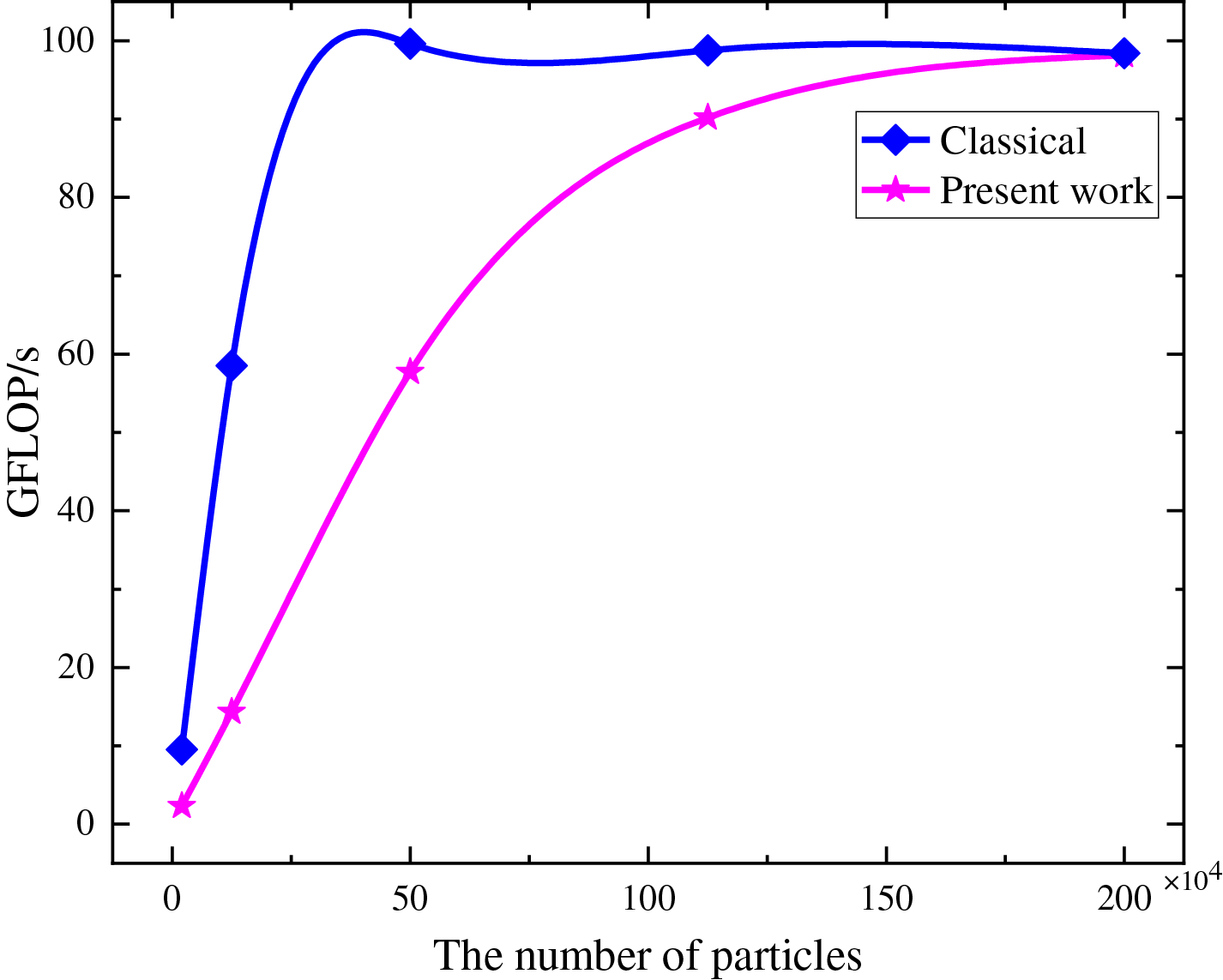
Figure 11: Computational performance as a function of the computing scale
Fig. 12 displays total runtime of each scheme and the corresponding speedup ratios without considering the time for data transfer. Due to domain partitioning, the subdomain-based parallel scheme involves more complex data access operations compared to the classical parallel scheme, which leads to increased time consumption, especially for small computation models. Thus, the subdomain-based parallel scheme exhibits lower runtime efficiency for small models, as shown in Fig. 12b. However, as the number of particles increases, the advantages of the subdomain-based scheme in the neighbor search become significant, and thus its computational efficiency gradually surpasses that of the classical parallel scheme. This further demonstrates the performance advantage of the proposed subdomain-based GPU parallel scheme in large-scale simulation calculations.
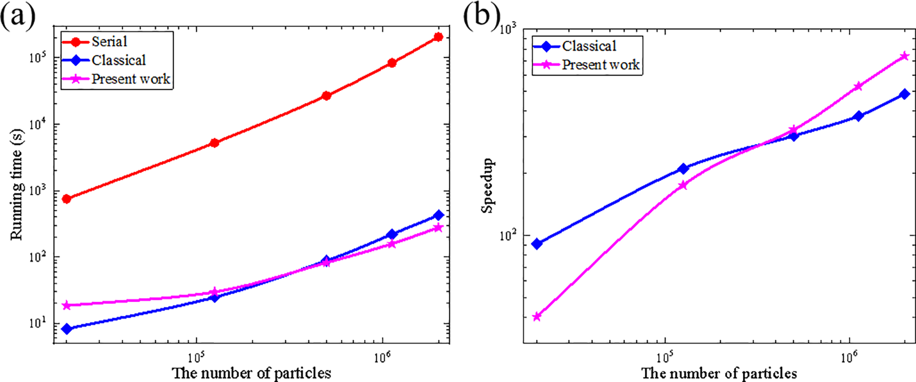
Figure 12: (a) Total running time for all scheme and (b) speedups as a function of the computing scale when not considering data transfer
Fig. 13 shows the total runtime of the three schemes and the speedup curve of each parallel scheme of the computational scale with the consideration of the time for data transfer. When the number of particles increases from 20 thousand to 2 million, the speedup of the classical parallel scheme increases from 90.9× to 483.5×, while the speedup of the subdomain-based parallel scheme increases from 21.5× to 127.7×. Since the subdomain-based parallel scheme requires the particle information in the GPU to be updated at each timestep, the generated data transfer time largely exceeds that of the classical parallel scheme, leading to limited improvements in the total runtime.
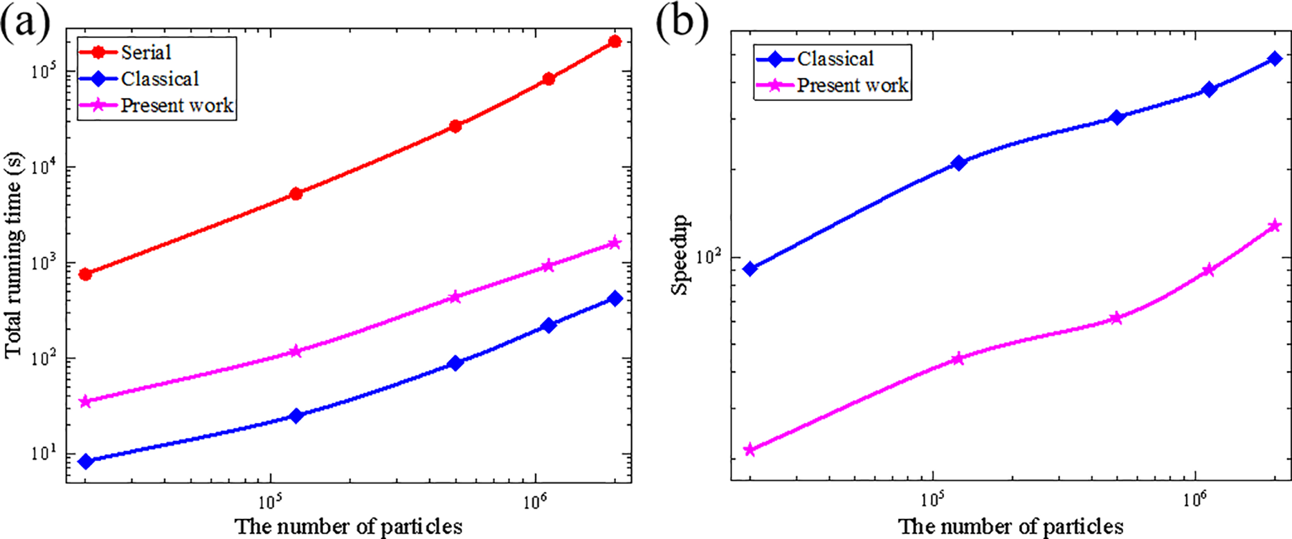
Figure 13: (a) Total running time for all scheme and (b) speedups curve with particle scale
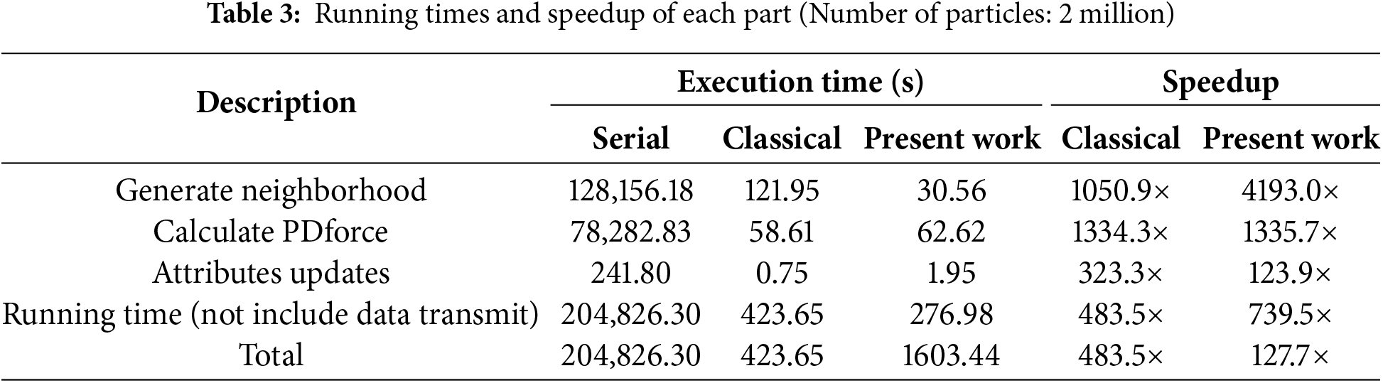
Table 3 lists the detailed running time for principal components when the total number of particles is 2 million. It is obvious that the subdomain-based scheme significantly improves efficiency in the neighbor search, while the performance in other components is approximately equal to those of the classical parallel scheme. If we do not consider the data transfer time, the subdomain-based parallel scheme achieves a speedup of 739.5×, while the classical parallel scheme only reaches 483.5×. However, when data transfer time is considered, the computational efficiency of the present parallel scheme decreases significantly to only 127.7×. Noteworthy, the graphics memory usage of the proposed parallel scheme was significantly reduced from 1476 to 684 MiB by approximately 53.7%, suggesting its advantages in large-scale simulations which requires large graphics memory.
3.2 A 2D Plate with a Circular Hole
As shown in Fig. 14, a 2D plate with a circular hole in the center was subjected to slow tensile loading along its horizontal edges. The materials properties of this model are isotropic. The virtual material layer (Rc) [6] at the top and bottom ends of the plate was located along the boundary of the actual material region (R) with a thickness of δ in the slow loading stretch area. The loading velocity was 2.7541 × 10⁻⁷ m/s, which is very slow and thus could be regarded as a quasi-static loading model. The particle spacing was set as Δ = 0.5 mm, resulting in a total of 9684 particles. A time step of Δt = 1 s was adopted, and the entire computation process iterates 1000 times. Other model parameters are shown in Table 4. Using the subdomain-based parallel scheme, the model was also divided into the four subdomains for computation.
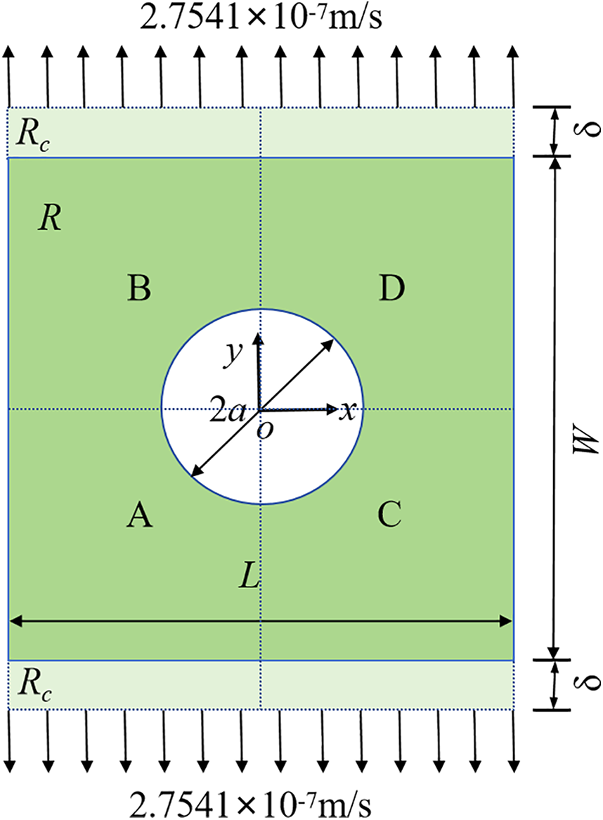
Figure 14: Geometry of the plate with a circular hole
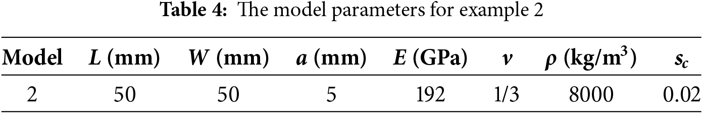
Fig. 15 shows the crack path. Although there are no initial cracks, crack nucleates from the stress concentration areas and then propagates at the 675 s (Fig. 15a). At the 700 s (Fig. 15b), the local damage values φ of some particles exceeds 0.38, resulting in self-similar crack propagation. Since the loading velocity is very slow, a typical quasi-static loading characteristic, the crack continues to expand towards the vertical boundaries as shown in Fig. 15c,d. This highlights the advantage of PD theory in addressing fracture problems without a pre-crack.
Figure 15: Crack path in the plate with a circular hole, (a) 675 s, (b) 700 s, (c) 800 s, (d) 1000 s
In addition, the acceleration effect of the proposed subdomain-based parallel scheme was then evaluated by examining the total running time, as shown in Fig. S2 of the Supplementary Material. The results exhibit similar trends with those of example 1, as suggested in the Supplementary Material.
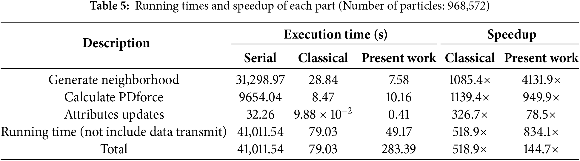
Table 5 lists the detailed running time for principal components when the total number of particles is 968,572. It is obvious that the subdomain-based scheme significantly improves efficiency in the neighbor search, while the performance in other components is approximately equal to those of the classical parallel scheme. If we do not consider the data transfer time, the subdomain-based parallel scheme achieves a speedup of 834.1×, while the classical parallel scheme only reaches 518.9×. However, when data transfer time is considered, the computational efficiency of the present parallel scheme decreases significantly to only 144.7×. Notably, its graphics memory usage was significantly reduced from 1050 to 580 MiB, a reduction of about 44.8%.
3.3 A 2D Plate with a Pre-Existing Crack
As shown in Fig. 16, the third example was a rapidly stretching 2D plate with a horizontal crack of 0.01 m in the center along its horizontal edge, with two loading velocities (v1 = 20 m/s; v2 = 50 m/s). The materials properties of this model are isotropic. Similar to example 2, the virtual material layer (Rc) at the top and bottom edges of the plate was the loading region with a thickness of δ along the boundary of the actual material area R. Using the subdomain-based parallel scheme, the model was also divided into the four subdomains for computation. The cracked plate was a 2D transient problem, which was solved using the BB-PD model and the CDEI method. The particle spacing was set to be Δ = 0.1 mm, resulting in a total of 0.25 million particles. The time step is Δt = 1.3367 × 10⁻⁸ s. The entire computation process iterates 1250 times, and other model parameters are shown in Table 6.
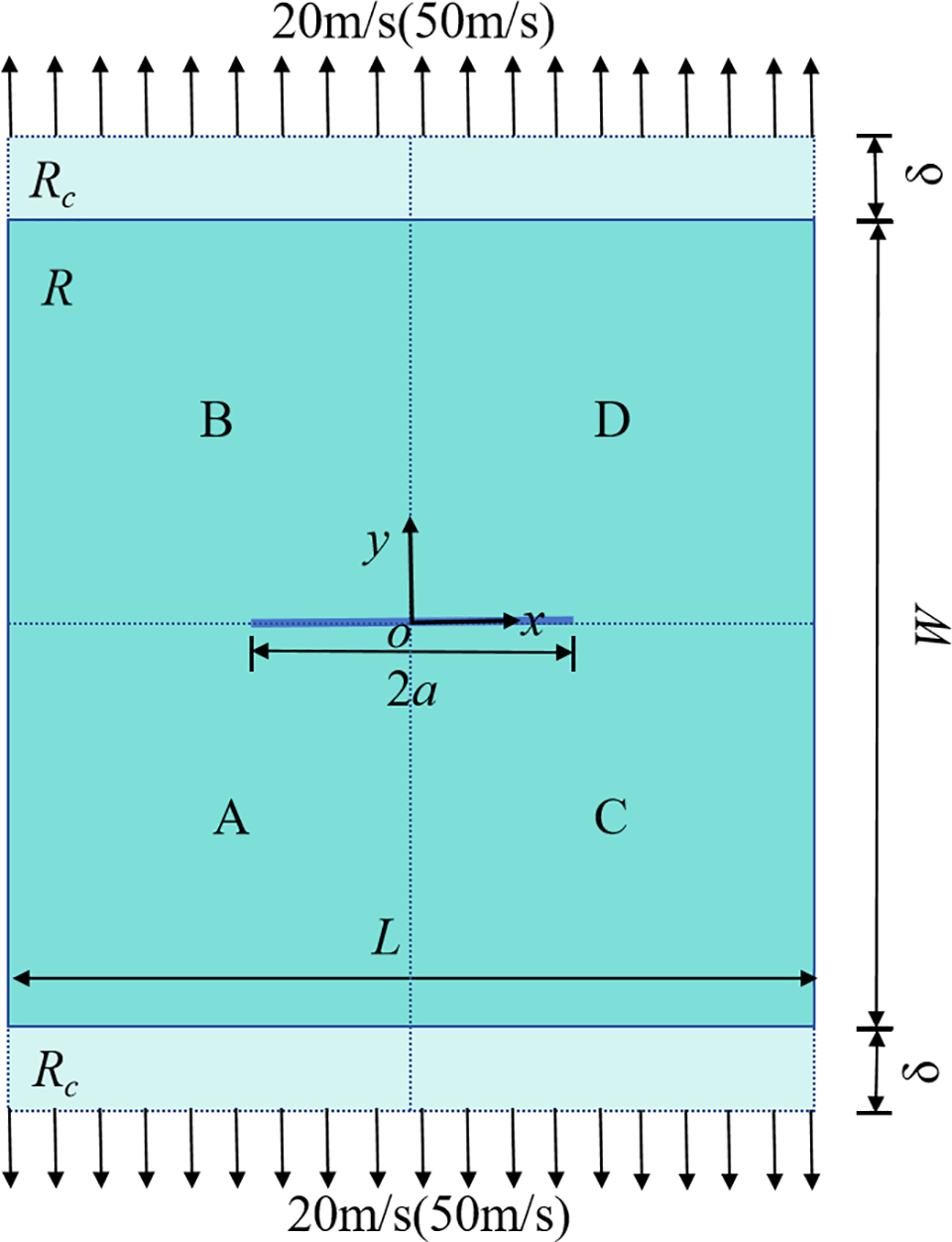
Figure 16: Geometry of a 2D plate with a pre-existing crack
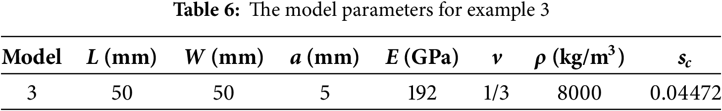
Fig. 17 shows the crack pattern for velocity of 20 and 50 m/s, at 16.7 μs, respectively. At 20 m/s, significant self-similar crack propagation can be observed (see Fig. 17a), which is a typical mode-I type of crack. The crack tip is determined by the local damage value φ of any particle along the x-axis exceeding 0.38, resulting in the relationship between crack propagation distance and time, as shown in Fig. 18. The crack propagates fast in the range of 12 to 16 μs, with a propagation speed of approximately 1750 m/s, which is lower than the upper limit of the mode-I type crack propagation speed of 2800 m/s (the Rayleigh wave speed) [5]. When the loading speed increases to 50 m/s, the crack pattern changes from self-similar to bifurcated, as shown in Fig. 17b. This demonstrates that the PD theory can capture very complex crack branching phenomena without the use of any external criteria to trigger crack bifurcation.
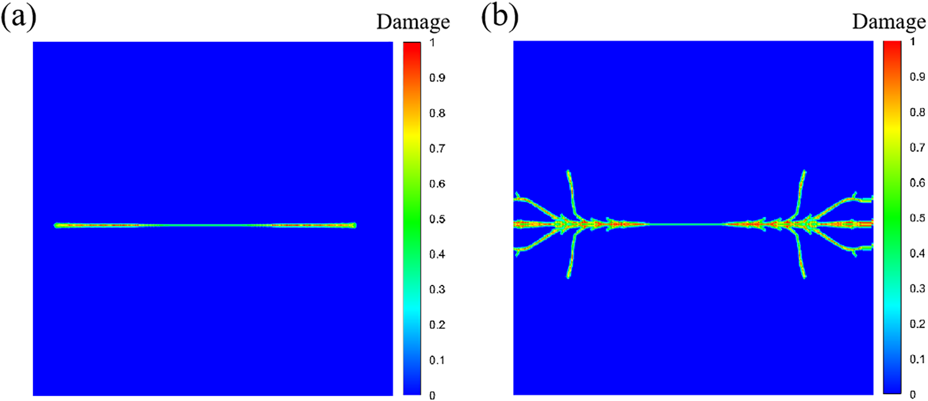
Figure 17: Crack patterns under different loading speeds, (a) v = 20 m/s, (b) v = 50 m/s
Figure 18: Crack propagation distance over time at a loading speed of 20 m/s
In addition, the acceleration effect of the proposed subdomain-based parallel scheme was evaluated by examining the total running time, as shown in Fig. S3 of the Supplementary Material. The results exhibit similar trends with those of example 1, as suggested in the Supplementary Material.
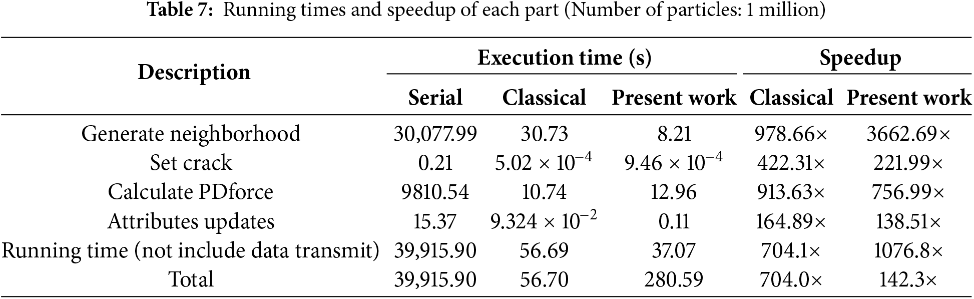
Table 7 lists the detailed running time for principal components when the total number of particles is 1 million. Particularly, the efficiency in the neighbor search are significantly enhanced, while the performance in other components is approximately equal to those of the classical parallel scheme. If we do not consider the data transfer time, the subdomain-based parallel scheme achieves a speedup of 1076.8×, while the classical parallel scheme only reaches 704.1×. However, when data transfer time is considered, the computational efficiency of the present parallel scheme decreases significantly to only 142.3×. Noteworthy, its graphics memory usage was reduced from 1032 to 574 MiB, a reduction of about 44.4%.
As shown in Fig. 19, the fourth example was a column subjected to compressive loading. The compressive load was applied by imposing prescribed displacement conditions within the neighborhood radius at both ends of the block. Specifically, a linearly increasing displacement was applied in the boundary region (Rc) at each time step, which reaches 0.05 mm at step 1000, and then, remains constant. Using the subdomain-based parallel scheme, the model was also divided into four subdomains for computation, as shown in Fig. 19. This experiment was a 3D quasi-static problem, which was solved using the ADR method. The particle spacing was Δ = 0.05 mm, with a total of 13,168 particles. The time step was Δt = 1.0 s, and the total number of time steps is 20,000. Other detailed parameters are shown in Table 8.
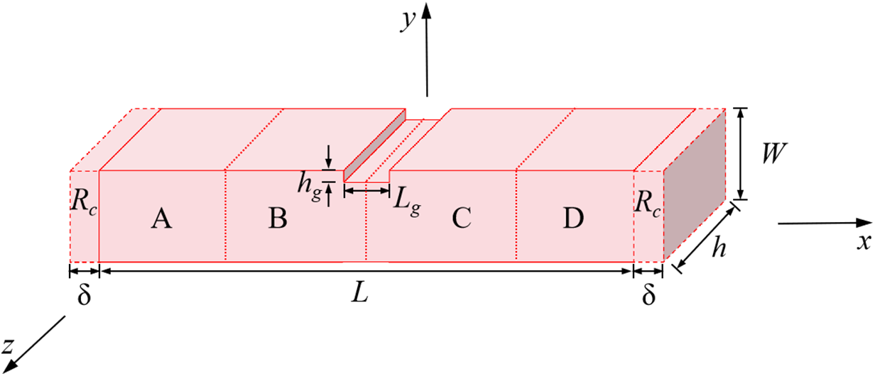
Figure 19: Geometry of a 3D column with a notch
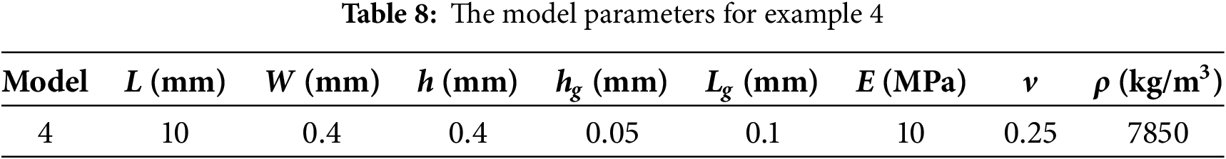
Fig. 20 shows displacement in the -z direction and the deformation shape of the column, which suggests that the maximum displacement appears in the middle of the column and is well consistent with experimental observations. This further verifies the accuracy of the BB-PD modeling.
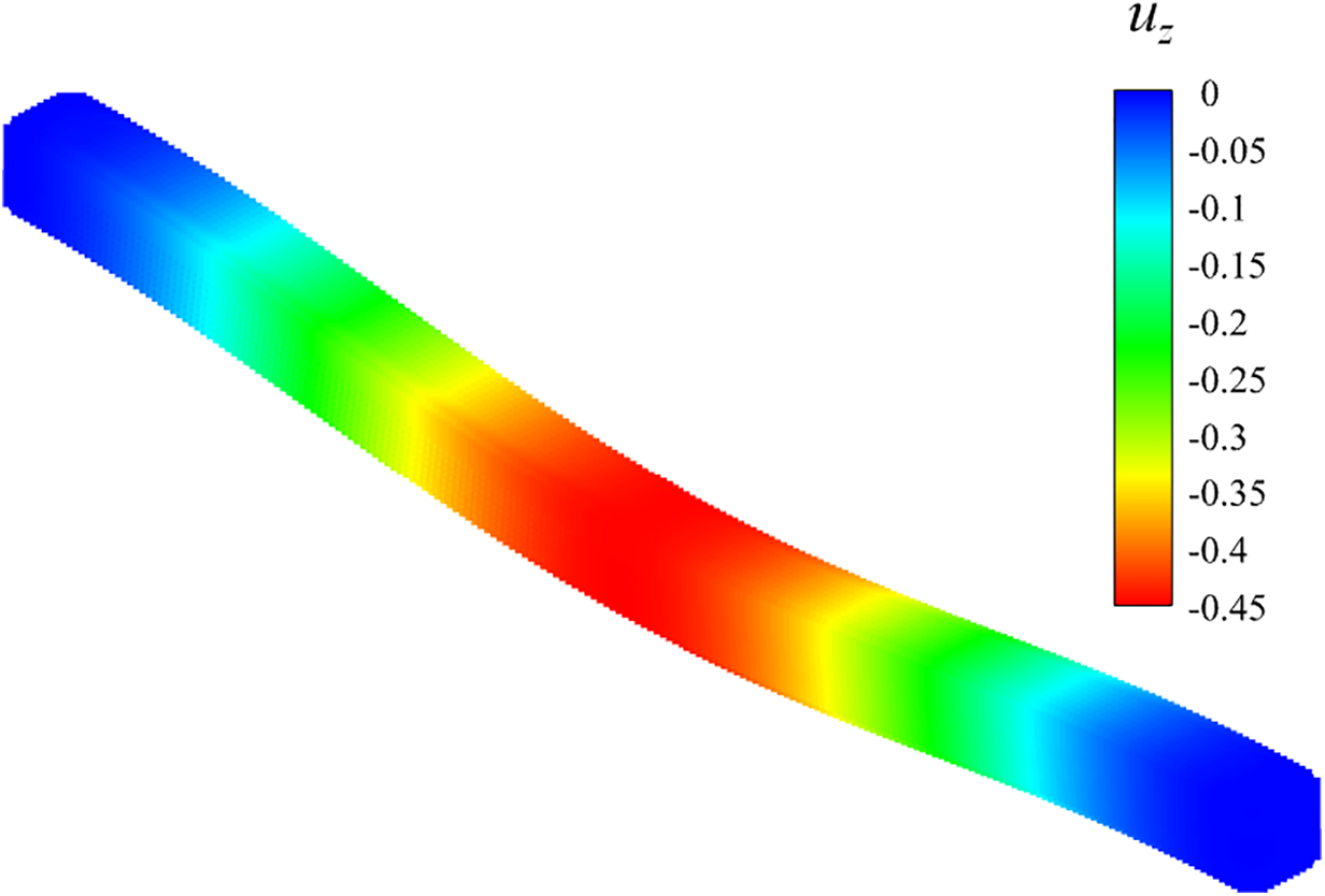
Figure 20: Displacement in the -z direction and deformation shape of the column
To analyze the computational efficiency of the subdomain-based GPU parallel scheme, we then gradually increased the total number of particles to 2,428,248. Here, although this case required 20,000 timesteps to reach convergence, we only employed 1000 timesteps to evaluate the computational efficiency, because the runtime of the serial program would become very long when the number of particles reaches millions.
The acceleration effect of the proposed subdomain-based parallel scheme was evaluated by examining the total running time, as shown in Fig. S4 of the Supplementary Material. The results exhibit similar trends with those of example 1, as suggested in the Supplementary Material.
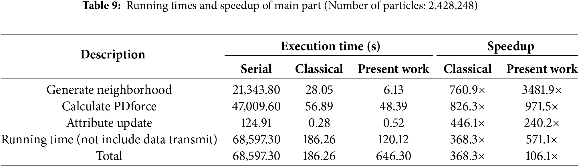
Table 9 lists the detailed running time for principal components with the total number of particles of 2,428,248. The results suggest that this subdomain-based scheme significantly improves efficiency in the neighbor search, while the time in other components is approximately equal to that of the classical parallel scheme. If we do not consider the data transfer time, the subdomain-based parallel scheme achieves a speedup of 571.1×, while the classical parallel scheme only reaches 368.3×. If the data transfer time is considered, the computational efficiency of the present parallel scheme decreases significantly to only 106.1×. Noteworthy, the graphics memory usage of the subdomain-based parallel scheme was significantly reduced from 6890 to 2130 MiB, a reduction of about 69.1%.
3.5 Kalthoff-Winkler Experiment
The next numerical example was the Kalthoff-Winkler experiment, which was a dynamic fracture benchmark problem. As shown in Fig. 21, the experiment investigated the impact of a cylindrical object on a steel plate with two cracks. In this simulation, the projectile was treated as a rigid body with diameter D = 50 mm, height H = 50 mm, mass m = 1.57 kg, and an initial downward impact velocity v0 = 32 m/s. The steel plate was unconstrained in displacement and is initially static. Using the subdomain-based parallel scheme, the model was also divided into the four subdomains for computation, as shown in Fig. 21. This experiment was a 3D transient impact problem, which was solved using the CDEI method. The particle spacing was Δ = 1 mm, with a total of 179,100 particles. The time step was Δt = 1.3367 × 10⁻⁸ s, and the total number of time steps is 1350. Other detailed parameters are shown in the Table 10.
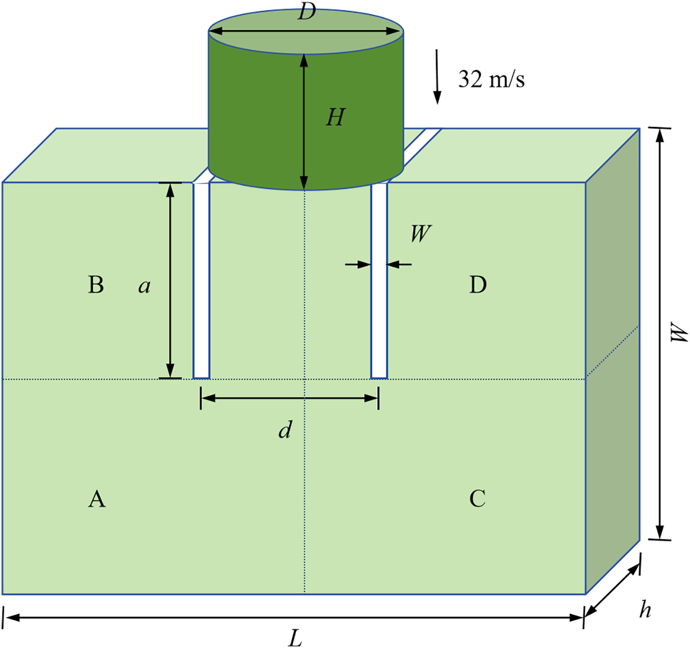
Figure 21: Geometry of Kalthoff-Winkler experiment
Fig. 22 shows the crack path at a timestep of 1350, corresponding to 18.045 μs. It suggests that the crack initiates from the tip of the pre-crack and propagates rapidly with a deflection angle of approximately 68° from the centerline, eventually forming a symmetric X-shaped fracture pattern. This process exhibits the typical characteristics of dynamic brittle fracture, and the crack path is approximately straight, in excellent agreement with the experimental results [39].
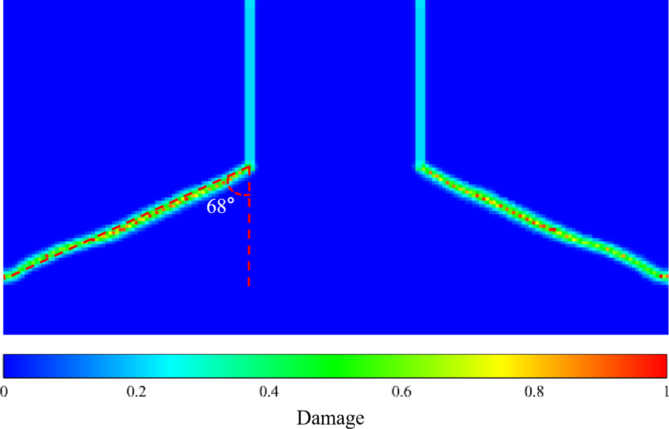
Figure 22: Crack patterns of last time steps (18.045 μs)
In addition, the acceleration effect of the proposed subdomain-based parallel scheme is evaluated by examining the total running time, as shown in Fig. S5 of the Supplementary Material. The results exhibit similar trends with those of example 1, as suggested in the Supplementary Material.
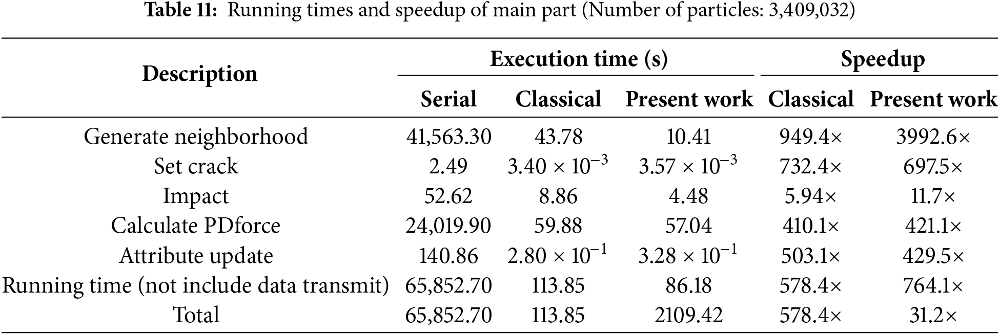
Table 11 lists the detailed running time for principal components when the total number of particles is 3,409,032. This subdomain-based scheme significantly improves efficiency in the neighbor search, while the performance in other components is approximately equal to those of the classical parallel scheme. If we do not consider the data transfer time, the subdomain-based parallel scheme achieves a speedup of 764.1×, while the classical parallel scheme only reaches 578.4×. However, when data transfer time is considered, the computational efficiency of the present parallel scheme decreases significantly to only 31.2×. In particular, its graphics memory usage was reduced from 9118 to 2764 MiB, a reduction of about 69.7%.
Notably, for complicated problems, using the same programming logic as classical parallel schemes may lead to significant efficiency reduction due to data transfer. For GPU parallelization, the time cost associated with reading global memory and data transfer is much higher than the time required to compute the variable. Therefore, when using the subdomain-based parallel scheme, it is advisable to only transfer necessary particle information and other data should be computed directly for minimizing the number of read and copy operations.
3.6 Application to Large Numerical Models
Generally, the required graphics memory increases almost linearly as the number of particles increases. Thus, it is challenging for classical parallel scheme to address very large PD models which require large graphics memory. To demonstrate the advantage of the subdomain-based parallel scheme in decreasing graphics memory usage, we further reduced the particle size of example 1 (Fig. 7) and example 4 (Fig. 19) to 0.16 and 0.005 mm, respectively, resulting in particle counts of 18,000,000 and 12,822,400.
Statistically, the example 1 contained 18 double-precision real array variables (double type) for displacement, velocity, acceleration, etc., and 2 integer array variables (int type) for recording the maximum number of family members of particles (1 element for each particle), and the family number of particles (100 elements for each particle), respectively. Therefore, we could obtain the total byte size of
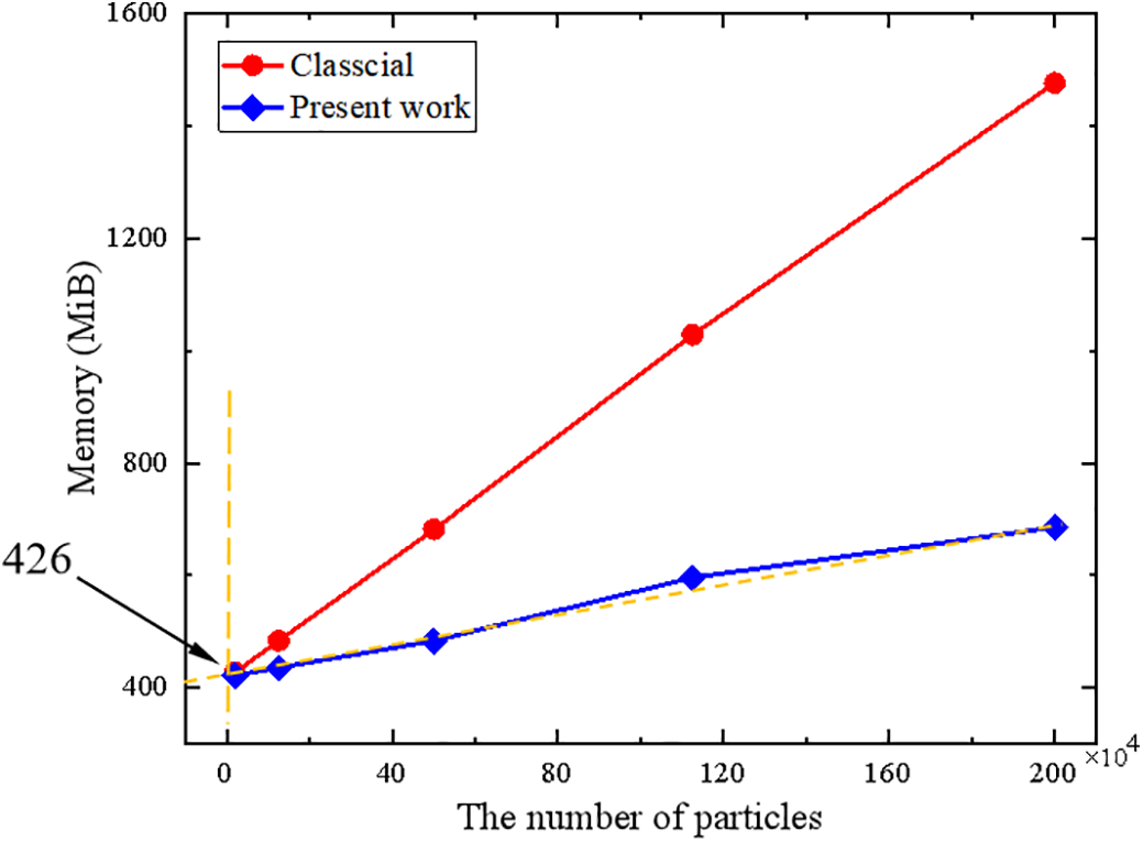
Figure 23: The required graphics memory changes with the computational scale (example 1)
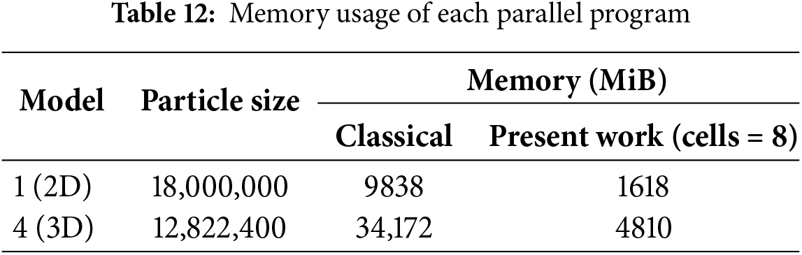
To clearly demonstrate the ability of this method to effectively reduce the graphics memory usage by controlling the size and number of subdomains, we divided the whole model into 1, 2, 4, and 8 regions. As shown in Fig. 24, with the increase in the number of divided domains, the memory usage of the subdomain-based parallel scheme decreases significantly. As shown in Table 12, when the number of particles for example 1 and example 4 reaches 18,000,000 and 12,822,400, respectively, the classical parallel scheme requires 9838 and 34,172 MiB of graphics memory. However, the subdomain-based scheme, with 8 subdomains, only requires 1618 and 4810 MiB, respectively, suggesting a reduction in memory usage of approximately 83.6% and 85.9%. This indicates that the proposed subdomain-based GPU parallel scheme can significantly reduce graphics memory usage, effectively addressing the issue of memory limitations in large-scale problems.
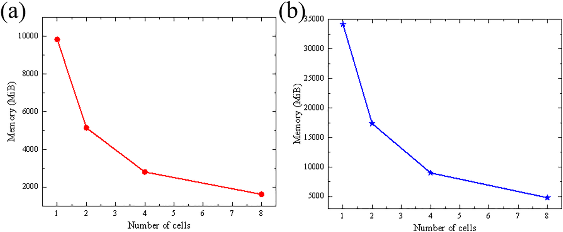
Figure 24: Impact of the number of cells on memory usage, (a) example 1, (b) example 4
Particularly, this subdomain-based parallel scheme was developed based on a single GPU. During the solution process, it inevitably requires multiple updates of particle information in the GPU, leading to a decrease in overall efficiency compared to classical parallel schemes that can fit the entire problem in memory. Therefore, in the application of this parallel scheme, it is essential to minimize unnecessary data transfer within the program. Ideally, only the necessary basic information should be transferred, while other intermediate variables should be computed directly within the kernel functions.
The proposed subdomain-based GPU parallel scheme demonstrates significant advantages in terms of graphics memory consumption when dealing with large-scale peridynamics computations. By partitioning the model into multiple subdomains, the required graphics memory is significantly reduced, enabling the simulation of 2D and 3D PD models with tens of millions of particles. Nevertheless, frequent data transfers between subdomains negatively affect the overall runtime performance, leading to lower efficiency compared to some existing optimization strategies.
Notably, the proposed approach is not mutually exclusive with other optimization strategies, which may be integrated with them to achieve superior performance. For example, the bond-based mapping has been proven to effectively unroll the inner loop during time integration [25,27]; designing more efficient memory access strategies can accelerate data retrieval [40]; and adopting mixed-precision computing can further enhance computational efficiency in non-critical regions [19]. These strategies provide promising pathways for improving the computational efficiency of the algorithm.
In addition, asynchronous memory operations provided by the CUDA platform also hold promise for further optimization of the proposed parallel scheme. Using “cudaMemcpyAsync”, particle information of the next subdomain can be copied to the device while performing computations for the current subdomain. However, it should be noted that this only works with pinned memory, otherwise, the asynchronous copy degrades to a synchronous operation. Moreover, asynchronous memory operations would require multiple subdomains to reside on the device simultaneously, increasing graphics memory consumption and potentially affecting the value of the correction coefficient a in Eq. (14). Nevertheless, this approach can greatly improve data transfer efficiency, thereby mitigating the current scheme’s limitations in data movement.
Generally, future research can focus on the effective integration of the proposed subdomain-based scheme with advanced GPU parallelization techniques. Such developments could lead to a more sophisticated and comprehensive GPU parallel architecture, ultimately elevating the performance of large-scale simulations to a new level.
In summary, we proposed a GPU parallel scheme of subdomain computing based on the cell-linked list method. Compared to classical parallel schemes, this approach divides the model into several subdomains. By controlling the size and number of these subdomains, large 2D and 3D PD models can be simulated with significantly reduced graphics memory and improved acceleration performance in key computational steps. The main conclusions are shown as follows:
(1) The subdomain-based parallel scheme demonstrates sufficient efficiency in examining complicated problems, in which the estimated crack extension patterns align well with experimental results. Moreover, it significantly improves computational efficiency compared to the serial program.
(2) The present parallel scheme exhibits excellent efficiency in the neighbor search, which leads to a significant improvement in overall running efficiency compared to classical parallel schemes when not considering the time for data transmission. However, it should be noted that the data transmission required for subdomain-based parallel computation can negatively impact the overall computational efficiency.
(3) We applied this subdomain-based parallel scheme to a 2D PD numerical example with 18,000,000 particles and a 3D PD example with 12,822,400 particles. As the number of subdomains increases, graphics memory consumption gradually decreases. Notably, when the number of subdomains reaches 8, the graphics memory usage is reduced by 83.6% and 85.9%, respectively. This is the primary advantages of the proposed scheme, as it enables large-scale simulations on hardware with limited graphics memory.
Acknowledgement: The authors acknowledge the financial support from the National Natural Science Foundation of China.
Funding Statement: Jun Li was supported by National Natural Science Foundation of China (No.: U2441215). Lisheng Liu and Xin Lai were supported by National Natural Science Foundation of China (No.: 52494933).
Author Contributions: Lisheng Liu conceived and designed the parallel scheme. Zuokun Yang constructed the corresponding numerical model performed the simulations. Xin Lai evaluated the feasibility of the algorithm and help the revision. Jun Li completed the revision and refinement. All authors provided insights into data analysis and wrote the manuscript. All authors reviewed the results and approved the final version of the manuscript.
Availability of Data and Materials: The authors confirm that the data supporting the findings of this study are available within the article and Supplementary Material. Raw data that support the findings of this study are available from the corresponding author.
Ethics Approval: Not applicable.
Conflicts of Interest: The authors declare that they have no known competing financial interests or personal relationships that could have appeared to influence the work reported in this paper.
Supplementary Materials: The supplementary material is available online at https://www.techscience.com/doi/10.32604/cmes.2026.075980/s1. The Supplementary Material includes the following data: (1) Table S1 shows the corresponding code for neighbor search implemented using the three different schemes. (2) Fig. S1 shows the variation in GFLOPs/s per watt as the particle number changes across different GPU architectures (3) Fig. S2 shows the variation in running efficiency as the particle number changes for example 2 (a plate with a circular hole). (4) Fig. S3 shows the variation in running efficiency as the particle scale changes for example 3 (a 2D plate with a pre-existing crack). (5) Fig. S4 shows the variation in running efficiency as the particle scale changes for example 4 (a 3D column). (6) Fig. S5 shows the variation in running efficiency as the particle scale changes for example 5 (Kalthoff-Winkler experiment). (7) Fig. S6 shows the variation of graphics memory required for example 4 with the computation scale.
References
1. Klocke F, Beck T, Hoppe S, Krieg T, Müller N, Nöthe T, et al. Examples of FEM application in manufacturing technology. J Mater Process Technol. 2002;120(1–3):450–7. doi:10.1016/S0924-0136(01)01210-9. [Google Scholar] [CrossRef]
2. Moukalled F, Mangani L, Darwish M. The finite volume method. In: The finite volume method in computational fluid dynamics. Cham, Switzerland: Springer International Publishing; 2015. p. 103–35. doi:10.1007/978-3-319-16874-6_5. [Google Scholar] [CrossRef]
3. Solomon IJ, Sevvel P, Gunasekaran J. A review on the various processing parameters in FDM. Mater Today Proc. 2021;37:509–14. doi:10.1016/j.matpr.2020.05.484. [Google Scholar] [CrossRef]
4. Silling SA. Reformulation of elasticity theory for discontinuities and long-range forces. J Mech Phys Solids. 2000;48(1):175–209. doi:10.1016/S0022-5096(99)00029-0. [Google Scholar] [CrossRef]
5. Silling SA, Askari E. A meshfree method based on the peridynamic model of solid mechanics. Comput Struct. 2005;83(17–18):1526–35. doi:10.1016/j.compstruc.2004.11.026. [Google Scholar] [CrossRef]
6. Silling SA, Epton M, Weckner O, Xu J, Askari E. Peridynamic states and constitutive modeling. J Elast. 2007;88(2):151–84. doi:10.1007/s10659-007-9125-1. [Google Scholar] [CrossRef]
7. Liu Y, Liu L, Mei H, Liu Q, Lai X. A modified rate-dependent peridynamic model with rotation effect for dynamic mechanical behavior of ceramic materials. Comput Meth Appl Mech Eng. 2022;388:114246. doi:10.1016/j.cma.2021.114246. [Google Scholar] [CrossRef]
8. Jafaraghaei Y, Yu T, Bui TQ. Peridynamics simulation of impact failure in glass plates. Theor Appl Fract Mech. 2022;121:103424. doi:10.1016/j.tafmec.2022.103424. [Google Scholar] [CrossRef]
9. Sun C, Huang Z. Peridynamic simulation to impacting damage in composite laminate. Compos Struct. 2016;138:335–41. doi:10.1016/j.compstruct.2015.12.001. [Google Scholar] [CrossRef]
10. Hattori G, Hobbs M, Orr J. A review on the developments of peridynamics for reinforced concrete structures. Arch Comput Meth Eng. 2021;28(7):4655–86. doi:10.1007/s11831-021-09549-y. [Google Scholar] [CrossRef]
11. Ouchi H, Katiyar A, Foster JT, Sharma MM. A peridynamics model for the propagation of hydraulic fractures in naturally fractured reservoirs. SPE J. 2017;22(4):1082–102. doi:10.2118/173361-pa. [Google Scholar] [CrossRef]
12. Madenci E, Oterkus E. Peridynamic theory. In: Peridynamic theory and its applications. New York, NY, USA: Springer; 2013. p. 19–43. doi:10.1007/978-1-4614-8465-3_2. [Google Scholar] [CrossRef]
13. Jafarzadeh S, Hillman M. An ultra-high-speed reproducing kernel particle method. Comput Mech. 2025;76(2):279–321. doi:10.1007/s00466-025-02599-0. [Google Scholar] [CrossRef]
14. Zheng G, Li R, Shen G, Zhang X. A parallel acceleration GPU algorithm for large deformation of thin shell structures based on peridynamics. Eng Comput. 2024;40(5):3009–30. doi:10.1007/s00366-024-01951-x. [Google Scholar] [CrossRef]
15. Liu GR, Liu MB. Smoothed particle hydrodynamics—a meshfree particle method. Singapore: WorldScientific; 2003. doi:10.1142/9789812564405. [Google Scholar] [CrossRef]
16. Macek RW, Silling SA. Peridynamics via finite element analysis. Finite Elem Anal Des. 2007;43(15):1169–78. doi:10.1016/j.finel.2007.08.012. [Google Scholar] [CrossRef]
17. Domínguez JM, Crespo AJC, Gómez-Gesteira M. Optimization strategies for CPU and GPU implementations of a smoothed particle hydrodynamics method. Comput Phys Commun. 2013;184(3):617–27. doi:10.1016/j.cpc.2012.10.015. [Google Scholar] [CrossRef]
18. Yu Y, Bargos FF, You H, Parks ML, Bittencourt ML, Karniadakis GE. A partitioned coupling framework for peridynamics and classical theory: analysis and simulations. Comput Meth Appl Mech Eng. 2018;340:905–31. doi:10.1016/j.cma.2018.06.008. [Google Scholar] [CrossRef]
19. Mao Z, Li X, Hu S, Gopalakrishnan G, Li A. A GPU accelerated mixed-precision smoothed particle hydrodynamics framework with cell-based relative coordinates. Eng Anal Bound Elem. 2024;161:113–25. doi:10.1016/j.enganabound.2024.01.020. [Google Scholar] [CrossRef]
20. Xu X, D’Elia M, Foster JT. A machine-learning framework for peridynamic material models with physical constraints. Comput Meth Appl Mech Eng. 2021;386:114062. doi:10.1016/j.cma.2021.114062. [Google Scholar] [CrossRef]
21. Slattery SR. Mesh-free data transfer algorithms for partitioned multiphysics problems: conservation, accuracy, and parallelism. J Comput Phys. 2016;307:164–88. doi:10.1016/j.jcp.2015.11.055. [Google Scholar] [CrossRef]
22. Parks ML, Littlewood DJ, Mitchell JA, Silling SA. Peridigm users’ guide, v1.0.0. Livermore, CA, USA: Sandia National Laboratories (SNL); 2012. doi:10.2172/1055619. [Google Scholar] [CrossRef]
23. Fan H, Li S. Parallel peridynamics-SPH simulation of explosion induced soil fragmentation by using OpenMP. Comput Part Mech. 2017;4(2):199–211. doi:10.1007/s40571-016-0116-5. [Google Scholar] [CrossRef]
24. Choquette J, Gandhi W, Giroux O, Stam N, Krashinsky R. NVIDIA A100 tensor core GPU: performance and innovation. IEEE Micro. 2021;41(2):29–35. doi:10.1109/MM.2021.3061394. [Google Scholar] [CrossRef]
25. Boys B, Dodwell TJ, Hobbs M, Girolami M. PeriPy—a high performance OpenCL peridynamics package. Comput Meth Appl Mech Eng. 2021;386:114085. doi:10.1016/j.cma.2021.114085. [Google Scholar] [CrossRef]
26. Crespo AJC, Domínguez JM, Rogers BD, Gómez-Gesteira M, Longshaw S, Canelas R, et al. DualSPHysics: open-source parallel CFD solver based on smoothed particle hydrodynamics (SPH). Comput Phys Commun. 2015;187:204–16. doi:10.1016/j.cpc.2014.10.004. [Google Scholar] [CrossRef]
27. Wang X, Wang Q, An B, He Q, Wang P, Wu J. A GPU parallel scheme for accelerating 2D and 3D peridynamics models. Theor Appl Fract Mech. 2022;121:103458. doi:10.1016/j.tafmec.2022.103458. [Google Scholar] [CrossRef]
28. Bartlett J, Storti D. A novel memory-optimized approach for large-scale peridynamics on the GPU. J Peridyn Nonlocal Model. 2023;5(4):472–90. doi:10.1007/s42102-022-00088-z. [Google Scholar] [CrossRef]
29. Wang X, Li S, Dong W, An B, Huang H, He Q, et al. Multi-GPU parallel acceleration scheme for meshfree peridynamic simulations. Theor Appl Fract Mech. 2024;131:104401. doi:10.1016/j.tafmec.2024.104401. [Google Scholar] [CrossRef]
30. Han TD, Abdelrahman TS. hiCUDA: high-level GPGPU programming. IEEE Trans Parallel Distrib Syst. 2011;22(1):78–90. doi:10.1109/TPDS.2010.62. [Google Scholar] [CrossRef]
31. Cheng J, Grossman M, McKercher T, Chapman B. Professional CUDA C programming. Indianapolis, IN, USA: Wrox; 2014. [Google Scholar]
32. Mattson W, Rice BM. Near-neighbor calculations using a modified cell-linked list method. Comput Phys Commun. 1999;119(2–3):135–48. doi:10.1016/S0010-4655(98)00203-3. [Google Scholar] [CrossRef]
33. Domínguez JM, Crespo AJC, Gómez-Gesteira M, Marongiu JC. Neighbour lists in smoothed particle hydrodynamics. Int J Numer Meth Fluids. 2011;67(12):2026–42. doi:10.1002/fld.2481. [Google Scholar] [CrossRef]
34. Hansani KGP, Sumith B, Karunasena HCP. Novel use of the cell-linked list algorithm to reduce computational time in meshfree based numerical models for plant cell drying. In: 2016 Manufacturing & Industrial Engineering Symposium (MIES); 2016 Oct 22–22; Colombo, Sri Lanka. p. 1–6. doi:10.1109/MIES.2016.7779991. [Google Scholar] [CrossRef]
35. Allen MP, Tildesley DJ. Computer simulation of liquids. 2nd ed. Oxford, UK: Oxford University Press; 2017. [Google Scholar]
36. Silling SA, Lehoucq RB. Convergence of peridynamics to classical elasticity theory. J Elast. 2008;93(1):13–37. doi:10.1007/s10659-008-9163-3. [Google Scholar] [CrossRef]
37. Kilic B, Madenci E. An adaptive dynamic relaxation method for quasi-static simulations using the peridynamic theory. Theor Appl Fract Mech. 2010;53(3):194–204. doi:10.1016/j.tafmec.2010.08.001. [Google Scholar] [CrossRef]
38. Mao Z, Liu GR. A Lagrangian gradient smoothing method for solid-flow problems using simplicial mesh. Int J Numer Meth Eng. 2018;113(5):858–90. doi:10.1002/nme.5639. [Google Scholar] [CrossRef]
39. Kalthoff JF, Winkler S. Failure mode transition at high rates of shear loading. Impact Load Dyn Behav Mater. 1988;1:185. [Google Scholar]
40. Yang Y, Su Z, Liu Y. A fast bond-based peridynamic program based on GPU parallel computing. Eng Anal Bound Elem. 2025;172:106133. doi:10.1016/j.enganabound.2025.106133. [Google Scholar] [CrossRef]
Cite This Article
 Copyright © 2026 The Author(s). Published by Tech Science Press.
This work is licensed under a Creative Commons Attribution 4.0 International License , which permits unrestricted use, distribution, and reproduction in any medium, provided the original work is properly cited.
 Downloads
 Citation Tools